96
2013 Microchip Technology Inc. DS52108A Microchip MRF24W Getting Started Guide for MRF24WB0MA/B, MRF24WG0MA/B for MLA v5
| Date post: | 09-Dec-2015 |
| Category: |
Documents |
| Upload: | diegogachet1618 |
| View: | 231 times |
| Download: | 3 times |
2013 Microchip Technology Inc. DS52108A
Microchip MRF24W Getting StartedGuide for MRF24WB0MA/B,
MRF24WG0MA/B for MLA v5
DS52108A-page 2 2013 Microchip Technology Inc.
Information contained in this publication regarding deviceapplications and the like is provided only for your convenienceand may be superseded by updates. It is your responsibility toensure that your application meets with your specifications.MICROCHIP MAKES NO REPRESENTATIONS ORWARRANTIES OF ANY KIND WHETHER EXPRESS ORIMPLIED, WRITTEN OR ORAL, STATUTORY OROTHERWISE, RELATED TO THE INFORMATION,INCLUDING BUT NOT LIMITED TO ITS CONDITION,QUALITY, PERFORMANCE, MERCHANTABILITY ORFITNESS FOR PURPOSE. Microchip disclaims all liabilityarising from this information and its use. Use of Microchipdevices in life support and/or safety applications is entirely atthe buyer’s risk, and the buyer agrees to defend, indemnify andhold harmless Microchip from any and all damages, claims,suits, or expenses resulting from such use. No licenses areconveyed, implicitly or otherwise, under any Microchipintellectual property rights.
Note the following details of the code protection feature on Microchip devices:
• Microchip products meet the specification contained in their particular Microchip Data Sheet.
• Microchip believes that its family of products is one of the most secure families of its kind on the market today, when used in the intended manner and under normal conditions.
• There are dishonest and possibly illegal methods used to breach the code protection feature. All of these methods, to our knowledge, require using the Microchip products in a manner outside the operating specifications contained in Microchip’s Data Sheets. Most likely, the person doing so is engaged in theft of intellectual property.
• Microchip is willing to work with the customer who is concerned about the integrity of their code.
• Neither Microchip nor any other semiconductor manufacturer can guarantee the security of their code. Code protection does not mean that we are guaranteeing the product as “unbreakable.”
Code protection is constantly evolving. We at Microchip are committed to continuously improving the code protection features of ourproducts. Attempts to break Microchip’s code protection feature may be a violation of the Digital Millennium Copyright Act. If such actsallow unauthorized access to your software or other copyrighted work, you may have a right to sue for relief under that Act.
Microchip received ISO/TS-16949:2009 certification for its worldwide headquarters, design and wafer fabrication facilities in Chandler and Tempe, Arizona; Gresham, Oregon and design centers in California and India. The Company’s quality system processes and procedures are for its PIC® MCUs and dsPIC® DSCs, KEELOQ® code hopping devices, Serial EEPROMs, microperipherals, nonvolatile memory and analog products. In addition, Microchip’s quality system for the design and manufacture of development systems is ISO 9001:2000 certified.
QUALITY MANAGEMENT SYSTEM
CERTIFIED BY DNV
== ISO/TS 16949 ==
Trademarks
The Microchip name and logo, the Microchip logo, dsPIC, FlashFlex, KEELOQ, KEELOQ logo, MPLAB, PIC, PICmicro, PICSTART, PIC32 logo, rfPIC, SST, SST Logo, SuperFlash and UNI/O are registered trademarks of Microchip Technology Incorporated in the U.S.A. and other countries.
FilterLab, Hampshire, HI-TECH C, Linear Active Thermistor, MTP, SEEVAL and The Embedded Control Solutions Company are registered trademarks of Microchip Technology Incorporated in the U.S.A.
Silicon Storage Technology is a registered trademark of Microchip Technology Inc. in other countries.
Analog-for-the-Digital Age, Application Maestro, BodyCom, chipKIT, chipKIT logo, CodeGuard, dsPICDEM, dsPICDEM.net, dsPICworks, dsSPEAK, ECAN, ECONOMONITOR, FanSense, HI-TIDE, In-Circuit Serial Programming, ICSP, Mindi, MiWi, MPASM, MPF, MPLAB Certified logo, MPLIB, MPLINK, mTouch, Omniscient Code Generation, PICC, PICC-18, PICDEM, PICDEM.net, PICkit, PICtail, REAL ICE, rfLAB, Select Mode, SQI, Serial Quad I/O, Total Endurance, TSHARC, UniWinDriver, WiperLock, ZENA and Z-Scale are trademarks of Microchip Technology Incorporated in the U.S.A. and other countries.
SQTP is a service mark of Microchip Technology Incorporated in the U.S.A.
GestIC and ULPP are registered trademarks of Microchip Technology Germany II GmbH & Co. & KG, a subsidiary of Microchip Technology Inc., in other countries.
All other trademarks mentioned herein are property of their respective companies.
© 2013, Microchip Technology Incorporated, Printed in the U.S.A., All Rights Reserved.
Printed on recycled paper.
ISBN: 978-1-62076-981-2
Object of Declaration: Microchip MRF24W Getting Started Guide for Microchip MRF24WBG0MA/B, MRF24WG0MA/B for MLA v5
2013 Microchip Technology Inc. Preliminary DS52108A-page 3

Microchip MRF24W Getting Started Guide for MRF24WB0MA/B, MRF24WG0MA/B for MLA v5
NOTES:
DS52108A-page 4 Preliminary 2013 Microchip Technology Inc.

MICROCHIP MRF24W GETTINGSTARTED GUIDE FOR
MRF24WB0MA/B, MRF24WG0MA/BFOR MLA V5
Table of Contents
Preface ........................................................................................................................... 7
Chapter 1. Getting Started with MRF24WB0MA/B or MRF24WG0MA/B ................. 131.1 Overview ...................................................................................................... 131.2 Scope ........................................................................................................... 131.3 Hardware ...................................................................................................... 131.4 Software ....................................................................................................... 141.5 References ................................................................................................... 141.6 Common Terms and Definitions ................................................................... 151.7 Local Network Topologies ............................................................................ 16
Chapter 2. Hardware Setup and Configuration ........................................................ 212.1 PICtail Setup ................................................................................................ 212.2 PICDEM.net 2 .............................................................................................. 212.3 Explorer 16 and PIC32 Starter Kit ................................................................ 222.4 Connecting the Development Board ............................................................ 222.5 Wireless Access Point (AP) Setup ............................................................... 232.6 Serial Monitor Setup ..................................................................................... 27
Chapter 3. Software Setup and Configuration ......................................................... 293.1 Software Items to Install ............................................................................... 293.2 Installing the Microchip MPLAB® X IDE ....................................................... 293.3 Installing the Microchip MPLAB® XC/C18 Compiler ..................................... 293.4 Installing the Microchip TCP/IP Stack with MRF24WB0MA/B or
MRF24WG0MA/B Wi-Fi® Driver ............................................................. 303.5 Installing Interim Code Releases .................................................................. 30
Chapter 4. Sample Application Demonstrations ...................................................... 314.1 Basic Demonstration Applications ................................................................ 314.2 Walkthrough and Instructions on Running the Demonstration ..................... 324.3 Opening Existing Projects ............................................................................ 334.4 Hardware Configuration Options .................................................................. 344.5 Compile-Time Configuration Options ........................................................... 354.6 Compiling and Downloading Images ............................................................ 474.7 Running TCP/IP – Demo App ...................................................................... 514.8 Running the TCPIP – WiFi Console ............................................................. 724.9 Running the TCPIP – WiFi EZConfig ........................................................... 78
Chapter 5. Microchip Development Board Specifics ............................................... 915.1 PICDEM.NET 2 Usage ................................................................................. 915.2 Explorer 16 Usage ........................................................................................ 915.3 Erasing EEPROM ......................................................................................... 92
2013 Microchip Technology Inc. Preliminary DS52108A-page 5
Microchip MRF24W Getting Started Guide for MRF24WB0MA/B, MRF24WG0MA/B for MLA v5
Appendix A. Appendix .................................................................................................93A.1 Microchip Hardware ..................................................................................... 93A.2 Microchip Software ...................................................................................... 93A.3 MRF24WB0MA/B or MRF24WG0MA/B Wi-Fi® Resources ......................... 93A.4 Tools ............................................................................................................ 93
Worldwide Sales and Service .....................................................................................96
DS52108A-page 6 Preliminary 2013 Microchip Technology Inc.
MICROCHIP MRF24W GETTINGSTARTED GUIDE FOR
MRF24WB0MA/B, MRF24WG0MA/B
FOR MLA V5Preface
INTRODUCTION
This preface contains general information that will be useful to know before using the MRF24WB0MA/B and/or MRF24WG0MA/B. Topics discussed in this preface include:
• Document Layout• Conventions Used in this Guide• Warranty Registration• Recommended Reading• The Microchip Web Site• Development Systems Customer Change Notification Service• Customer Support• Document Revision History
DOCUMENT LAYOUT
This user’s guide describes how to use the Microchip MRF24W Getting Started Guide for MRF24WB0MA/B, MRF24WG0MA/B for MLA v5. The document is organized as follows:
• Chapter 1. “Getting Started with MRF24WB0MA/B or MRF24WG0MA/B” – This chapter introduces the various wireless network topologies, terminologies, and a brief description of the hardware and software needed.
• Chapter 2. “Hardware Setup and Configuration” – This chapter provides information on how to set up the hardware to be used in the development environment.
• Chapter 3. “Software Setup and Configuration” – This chapter describes the software to be used in conjunction with the hardware.
• Chapter 4. “Sample Application Demonstrations” – This chapter describes the various applications released in the TCP/IP stack MLA release.
NOTICE TO CUSTOMERS
All documentation becomes dated, and this manual is no exception. Microchip tools and documentation are constantly evolving to meet customer needs, so some actual dialogs and/or tool descriptions may differ from those in this document. Please refer to our web site (www.microchip.com) to obtain the latest documentation available.
Documents are identified with a “DS” number. This number is located on the bottom of each page, in front of the page number. The numbering convention for the DS number is “DSXXXXXA”, where “XXXXX” is the document number and “A” is the revision level of the document.
For the most up-to-date information on development tools, see the MPLAB® IDE on-line help. Select the Help menu, and then Topics to open a list of available on-line help files.
2013 Microchip Technology Inc. Preliminary DS52108A-page 7
Microchip MRF24W Getting Started Guide for MRF24WB0MA/B, MRF24WG0MA/B for MLA v5
• Chapter 5. “Microchip Development Board Specifics” – This chapter provides the pin descriptions that interface the hardware platform to the MRF24W.
• Appendix A – This appendix provides the web links to access the hardware or software as described in this user guide.
DS52108A-page 8 Preliminary 2013 Microchip Technology Inc.
Preface
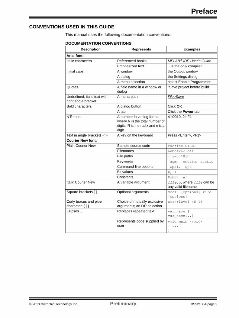
CONVENTIONS USED IN THIS GUIDE
This manual uses the following documentation conventions:
DOCUMENTATION CONVENTIONS
Description Represents Examples
Arial font:
Italic characters Referenced books MPLAB® IDE User’s Guide
Emphasized text ...is the only compiler...
Initial caps A window the Output window
A dialog the Settings dialog
A menu selection select Enable Programmer
Quotes A field name in a window or dialog
“Save project before build”
Underlined, italic text with right angle bracket
A menu path File>Save
Bold characters A dialog button Click OK
A tab Click the Power tab
N‘Rnnnn A number in verilog format, where N is the total number of digits, R is the radix and n is a digit.
4‘b0010, 2‘hF1
Text in angle brackets < > A key on the keyboard Press <Enter>, <F1>
Courier New font:
Plain Courier New Sample source code #define START
Filenames autoexec.bat
File paths c:\mcc18\h
Keywords _asm, _endasm, static
Command-line options -Opa+, -Opa-
Bit values 0, 1
Constants 0xFF, ‘A’
Italic Courier New A variable argument file.o, where file can be any valid filename
Square brackets [ ] Optional arguments mcc18 [options] file [options]
Curly braces and pipe character: { | }
Choice of mutually exclusive arguments; an OR selection
errorlevel {0|1}
Ellipses... Replaces repeated text var_name [, var_name...]
Represents code supplied by user
void main (void){ ...}
2013 Microchip Technology Inc. Preliminary DS52108A-page 9
Microchip MRF24W Getting Started Guide for MRF24WB0MA/B, MRF24WG0MA/B for MLA v5
WARRANTY REGISTRATION
Please complete the enclosed Warranty Registration Card and mail it promptly. Sending in the Warranty Registration Card entitles users to receive new product updates. Interim software releases are available at the Microchip web site.
RECOMMENDED READING
This user’s guide describes how to use MRF24WB0MA/B and/or MRF24WG0MA/B. The device-specific data sheets contain current information on programming the specific microcontroller or digital signal controller devices. Other useful documents are listed below. The following Microchip documents are available and recommended as supplemental reference resources:
MRF24WB0MA/MRF24WB0MB Data Sheet (DS70632)
MRF24WG0MA/MB Data Sheet (DS70686)
To obtain any of these documents, visit Microchip web site at www.microchip.com.
DS52108A-page 10 Preliminary 2013 Microchip Technology Inc.
Preface
THE MICROCHIP WEB SITE
Microchip provides online support via our web site at www.microchip.com. This web site is used as a means to make files and information easily available to customers. Accessible by using your favorite Internet browser, the web site contains the following information:
• Product Support – Data sheets and errata, application notes and sample programs, design resources, user’s guides and hardware support documents, latest software releases and archived software
• General Technical Support – Frequently Asked Questions (FAQs), technical support requests, online discussion groups, Microchip consultant program member listing
• Business of Microchip – Product selector and ordering guides, latest Microchip press releases, listing of seminars and events, listings of Microchip sales offices, distributors and factory representatives
DEVELOPMENT SYSTEMS CUSTOMER CHANGE NOTIFICATION SERVICE
Microchip’s customer notification service helps keep customers current on Microchip products. Subscribers will receive e-mail notification whenever there are changes, updates, revisions or errata related to a specified product family or development tool of interest.
To register, access the Microchip web site at www.microchip.com, click on Customer Change Notification and follow the registration instructions.
The Development Systems product group categories are:
• Compilers – The latest information on Microchip C compilers and other language tools. These include the MPLAB® C compiler; MPASM™ and MPLAB 16-bit assemblers; MPLINK™ and MPLAB 16-bit object linkers; and MPLIB™ and MPLAB 16-bit object librarians.
• Emulators – The latest information on the Microchip MPLAB REAL ICE™ in-circuit emulator.
• In-Circuit Debuggers – The latest information on the Microchip in-circuit debugger, MPLAB ICD 3.
• MPLAB IDE – The latest information on Microchip MPLAB IDE, the Windows® Integrated Development Environment for development systems tools. This list is focused on the MPLAB IDE, MPLAB SIM simulator, MPLAB IDE Project Manager and general editing and debugging features.
• Programmers – The latest information on Microchip programmers. These include the MPLAB PM3 device programmer and the PICkit™ 3 development programmers.
2013 Microchip Technology Inc. Preliminary DS52108A-page 11

Microchip MRF24W Getting Started Guide for MRF24WB0MA/B, MRF24WG0MA/B for MLA v5
CUSTOMER SUPPORT
Users of Microchip products can receive assistance through several channels:
• Distributor or Representative
• Local Sales Office
• Field Application Engineer (FAE)
• Technical Support
Customers should contact their distributor, representative or field application engineer (FAE) for support. Local sales offices are also available to help customers. A listing of sales offices and locations is included in the back of this document.
Technical support is available through the web site at: http://support.microchip.com.
DOCUMENT REVISION HISTORY
Revision A (January 2013)
This is the initial released version of the document
DS52108A-page 12 Preliminary 2013 Microchip Technology Inc.

MICROCHIP MRF24W GETTINGSTARTED GUIDE FOR
MRF24WB0MA/B, MRF24WG0MA/B
FOR MLA V5Chapter 1. Getting Started with MRF24WB0MA/B or MRF24WG0MA/B
1.1 OVERVIEW
MRF24WB0MA/B and MRF24WG0MA/B Wi-Fi® PICtail™ are the 802.11 module based boards for evaluating 802.11b/g wireless connectivity on the Microchip Technology’s processing platform. MRF24WB0MA/B and MRF24WG0MA/B Wi-Fi® PICtail™ are the expansion boards that are compatible with the Explorer 16 and PICDEM™.NET 2 development boards.
• MRF24WB0MA/B supports only 802.11b (1 Mbps, 2 Mbps)
• MRF24WG0MA/B supports both 802.11b and 802.11g
802.11b, ratified in 1999 is an extension of 802.11 that uses the same 2.4 GHz frequency band, and supports two additional transmission rates, 5.5 Mbps and 11 Mbps along with existing 1 Mbps and 2 Mbps.
802.11g, ratified in 2003 is backward compatible with 802.11b, and supports the additional transmission rates of 6 Mbps, 9 Mbps, 12 Mbps, 18 Mbps, 24 Mbps, 36 Mbps, 48 Mbps and 54 Mbps.
1.2 SCOPE
The Getting Started Guide covers these topics:
• MLA v5 based releases
• MPLAB® X IDE
1.3 HARDWARE
The following are required for developing or evaluating of the Microchip MRF24WB0MA/B and MRF24WG0MA/B Wi-Fi® module 802.11b/g solution:
• MRF24WB0MA/MB or MRF24WG0MA/B Wi-Fi® PICtail™
• One of the following Microchip hardware development platforms:
- Explorer 16 Development Board (PIC24 or PIC32 depending on the personality module)
- PICDEM.Net2 (PIC18)
- PIC32 Starter Kit and I/O Expansion Board
• One of the following Microchip development tools:
- MPLAB Real ICE
- MPLAB ICD
- PICKit™ 3 programmer with AC164110 RJ11 to ICSP adapter
• Power supply (different hardware configurations have different power require-ments. Use the AC power adapter that comes along with the kit)
2013 Microchip Technology Inc. Preliminary DS52108A-page 13
Microchip MRF24W Getting Started Guide for MRF24WB0MA/B, MRF24WG0MA/B for MLA v5
• 802.11 access point (AP) (b, b/g, or b/g/n) required for using the development board in Infrastructure BSS mode
- Linksys WRT54G or WRT54G2 is recommended, and it is used as a refer-ence in this document. If other types of APs are used, the approach remains similar and user must refer to the APs operating manual.
1.4 SOFTWARE
This user’s guide consists of sections on installing the Microchip MPLAB X IDE, the Microchip MRF24WB0MA/B or MRF24WG0MA/B Wi-Fi® SDK and TCP/IP stack, and the necessary changes to configure the demonstration software for networks with different characteristics apart from the default settings. Refer to Appendix A, for direct links to the specific Microchip software you may require for your project. The latest Microchip documentation is available on the Microchip web site, and takes precedence over software bundles on the installation CD. The latest MRF24WB0MA/B and MRF24WG0MA/B Wi-Fi® documentation is available on the Microchip Wi-Fi® support web site (http://www.microchip.com/pagehandler/en-us/technology/wifi), and is the most accurate.
This user’s guide documents how to configure the wireless network by hard coding the network parameters into the software, then compiling, and storing this information on the Microchip MCU. The software uses the C function calls to modify the values in variables used to keep the configurations. Customer application code can therefore create a user interface that allows scanning for networks and then configuring based on the end users selection. As an example of using the variables, the included demonstration projects have a number of source files to allow run-time configuration of the networks (for example, select Ad hoc or Infrastructure network type, change the SSID, change the security methods and keys, and so on).
The required software installation to build the project are:
• Microchip MPLAB® XC compiler
• Microchip MPLAB C18 compiler (PICDEM.Net 2 and PIC18)
• Microchip MPLAB X IDE
Refer to Appendix A, for download information.
1.5 REFERENCES
For more information, refer to the following:
• Microchip TCP/IP Stack Help
The help file comes with the TCP/IP source code releases.
DS52108A-page 14 Preliminary 2013 Microchip Technology Inc.
Introduction
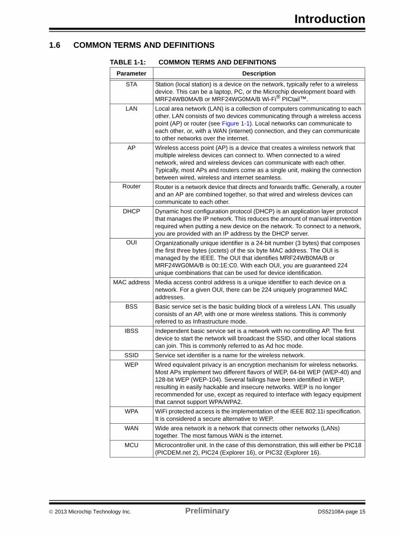
1.6 COMMON TERMS AND DEFINITIONS
TABLE 1-1: COMMON TERMS AND DEFINITIONS Parameter Description
STA Station (local station) is a device on the network, typically refer to a wireless device. This can be a laptop, PC, or the Microchip development board with MRF24WB0MA/B or MRF24WG0MA/B Wi-Fi® PICtail™.
LAN Local area network (LAN) is a collection of computers communicating to each other. LAN consists of two devices communicating through a wireless access point (AP) or router (see Figure 1-1). Local networks can communicate to each other, or, with a WAN (internet) connection, and they can communicate to other networks over the internet.
AP Wireless access point (AP) is a device that creates a wireless network that multiple wireless devices can connect to. When connected to a wired network, wired and wireless devices can communicate with each other. Typically, most APs and routers come as a single unit, making the connection between wired, wireless and internet seamless.
Router Router is a network device that directs and forwards traffic. Generally, a router and an AP are combined together, so that wired and wireless devices can communicate to each other.
DHCP Dynamic host configuration protocol (DHCP) is an application layer protocol that manages the IP network. This reduces the amount of manual intervention required when putting a new device on the network. To connect to a network, you are provided with an IP address by the DHCP server.
OUI Organizationally unique identifier is a 24-bit number (3 bytes) that composes the first three bytes (octets) of the six byte MAC address. The OUI is managed by the IEEE. The OUI that identifies MRF24WB0MA/B or MRF24WG0MA/B is 00:1E:C0. With each OUI, you are guaranteed 224 unique combinations that can be used for device identification.
MAC address Media access control address is a unique identifier to each device on a network. For a given OUI, there can be 224 uniquely programmed MAC addresses.
BSS Basic service set is the basic building block of a wireless LAN. This usually consists of an AP, with one or more wireless stations. This is commonly referred to as Infrastructure mode.
IBSS Independent basic service set is a network with no controlling AP. The first device to start the network will broadcast the SSID, and other local stations can join. This is commonly referred to as Ad hoc mode.
SSID Service set identifier is a name for the wireless network.
WEP Wired equivalent privacy is an encryption mechanism for wireless networks. Most APs implement two different flavors of WEP, 64-bit WEP (WEP-40) and 128-bit WEP (WEP-104). Several failings have been identified in WEP, resulting in easily hackable and insecure networks. WEP is no longer recommended for use, except as required to interface with legacy equipment that cannot support WPA/WPA2.
WPA WiFi protected access is the implementation of the IEEE 802.11i specification. It is considered a secure alternative to WEP.
WAN Wide area network is a network that connects other networks (LANs) together. The most famous WAN is the internet.
MCU Microcontroller unit. In the case of this demonstration, this will either be PIC18 (PICDEM.net 2), PIC24 (Explorer 16), or PIC32 (Explorer 16).
2013 Microchip Technology Inc. Preliminary DS52108A-page 15
Microchip MRF24W Getting Started Guide for MRF24WB0MA/B, MRF24WG0MA/B for MLA v5
1.7 LOCAL NETWORK TOPOLOGIES
1.7.1 Infrastructure Basic Service Set (BSS)
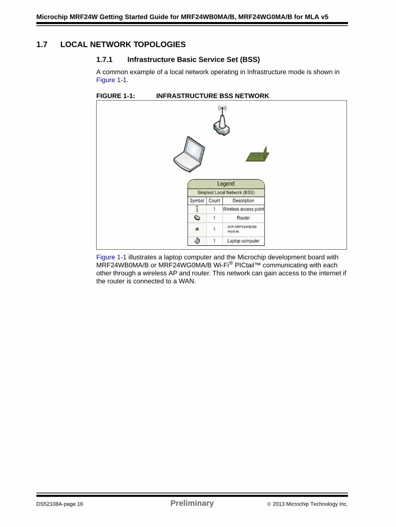
A common example of a local network operating in Infrastructure mode is shown in Figure 1-1.
FIGURE 1-1: INFRASTRUCTURE BSS NETWORK
Figure 1-1 illustrates a laptop computer and the Microchip development board with MRF24WB0MA/B or MRF24WG0MA/B Wi-Fi® PICtail™ communicating with each other through a wireless AP and router. This network can gain access to the internet if the router is connected to a WAN.
DS52108A-page 16 Preliminary 2013 Microchip Technology Inc.
Introduction
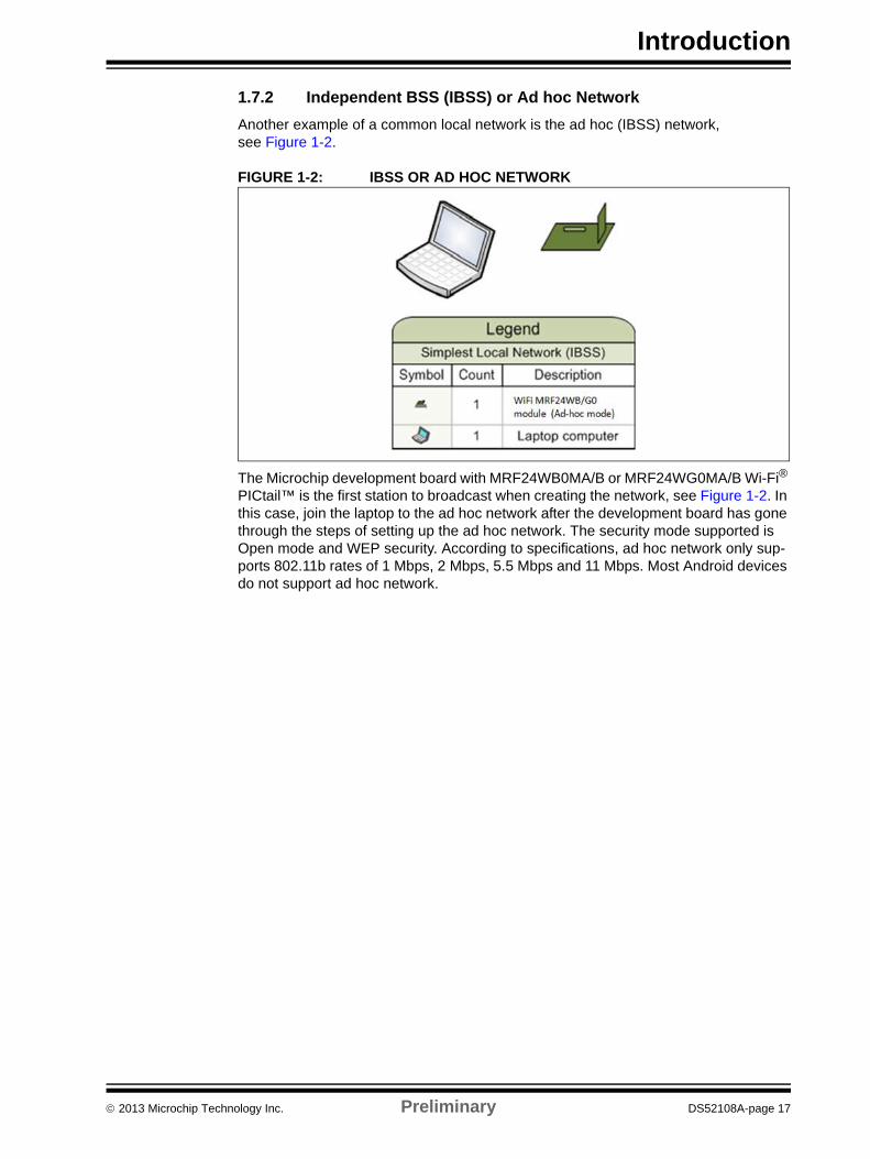
1.7.2 Independent BSS (IBSS) or Ad hoc Network
Another example of a common local network is the ad hoc (IBSS) network, see Figure 1-2.
FIGURE 1-2: IBSS OR AD HOC NETWORK
The Microchip development board with MRF24WB0MA/B or MRF24WG0MA/B Wi-Fi® PICtail™ is the first station to broadcast when creating the network, see Figure 1-2. In this case, join the laptop to the ad hoc network after the development board has gone through the steps of setting up the ad hoc network. The security mode supported is Open mode and WEP security. According to specifications, ad hoc network only sup-ports 802.11b rates of 1 Mbps, 2 Mbps, 5.5 Mbps and 11 Mbps. Most Android devices do not support ad hoc network.
2013 Microchip Technology Inc. Preliminary DS52108A-page 17
Microchip MRF24W Getting Started Guide for MRF24WB0MA/B, MRF24WG0MA/B for MLA v5
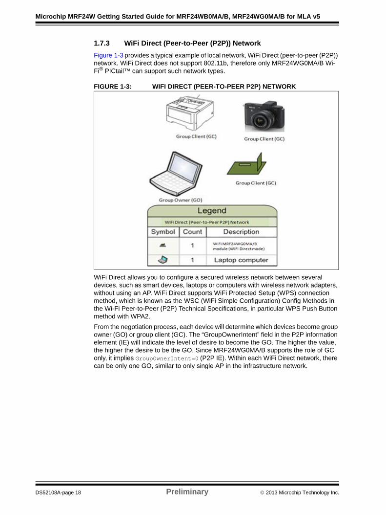
1.7.3 WiFi Direct (Peer-to-Peer (P2P)) Network
Figure 1-3 provides a typical example of local network, WiFi Direct (peer-to-peer (P2P)) network. WiFi Direct does not support 802.11b, therefore only MRF24WG0MA/B Wi-Fi® PICtail™ can support such network types.
FIGURE 1-3: WIFI DIRECT (PEER-TO-PEER P2P) NETWORK
WiFi Direct allows you to configure a secured wireless network between several devices, such as smart devices, laptops or computers with wireless network adapters, without using an AP. WiFi Direct supports WiFi Protected Setup (WPS) connection method, which is known as the WSC (WiFi Simple Configuration) Config Methods in the Wi-Fi Peer-to-Peer (P2P) Technical Specifications, in particular WPS Push Button method with WPA2.
From the negotiation process, each device will determine which devices become group owner (GO) or group client (GC). The “GroupOwnerIntent” field in the P2P information element (IE) will indicate the level of desire to become the GO. The higher the value, the higher the desire to be the GO. Since MRF24WG0MA/B supports the role of GC only, it implies GroupOwnerIntent=0 (P2P IE). Within each WiFi Direct network, there can be only one GO, similar to only single AP in the infrastructure network.
DS52108A-page 18 Preliminary 2013 Microchip Technology Inc.
Introduction
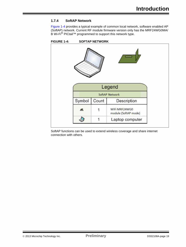
1.7.4 SoftAP Network
Figure 1-4 provides a typical example of common local network, software enabled AP (SoftAP) network. Current RF module firmware version only has the MRF24WG0MA/B Wi-Fi® PICtail™ programmed to support this network type.
FIGURE 1-4: SOFTAP NETWORK
SoftAP functions can be used to extend wireless coverage and share internet connection with others.
2013 Microchip Technology Inc. Preliminary DS52108A-page 19

Microchip MRF24W Getting Started Guide for MRF24WB0MA/B, MRF24WG0MA/B for MLA v5
NOTES:
DS52108A-page 20 Preliminary 2013 Microchip Technology Inc.
MICROCHIP MRF24W GETTINGSTARTED GUIDE FOR
MRF24WB0MA/B, MRF24WG0MA/B
FOR MLA V5Chapter 2. Hardware Setup and Configuration
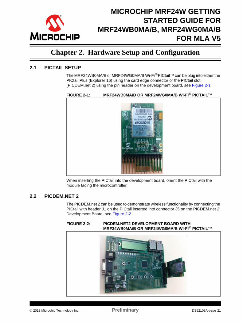
2.1 PICTAIL SETUP
The MRF24WB0MA/B or MRF24WG0MA/B Wi-Fi® PICtail™ can be plug into either the PICtail Plus (Explorer 16) using the card edge connector or the PICtail slot (PICDEM.net 2) using the pin header on the development board, see Figure 2-1.
FIGURE 2-1: MRF24WB0MA/B OR MRF24WG0MA/B WI-FI® PICTAIL™
When inserting the PICtail into the development board, orient the PICtail with the module facing the microcontroller.
2.2 PICDEM.NET 2
The PICDEM.net 2 can be used to demonstrate wireless functionality by connecting the PICtail with header J1 on the PICtail inserted into connector J5 on the PICDEM.net 2 Development Board, see Figure 2-2.
FIGURE 2-2: PICDEM.NET2 DEVELOPMENT BOARD WITH MRF24WB0MA/B OR MRF24WG0MA/B WI-FI® PICTAIL™
2013 Microchip Technology Inc. Preliminary DS52108A-page 21
Microchip MRF24W Getting Started Guide for MRF24WB0MA/B, MRF24WG0MA/B for MLA v5
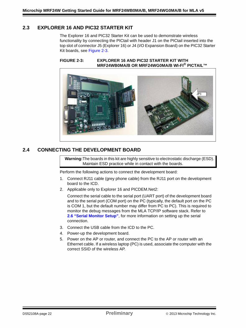
2.3 EXPLORER 16 AND PIC32 STARTER KIT
The Explorer 16 and PIC32 Starter Kit can be used to demonstrate wireless functionality by connecting the PICtail with header J1 on the PICtail inserted into the top slot of connector J5 (Explorer 16) or J4 (I/O Expansion Board) on the PIC32 Starter Kit boards, see Figure 2-3.
FIGURE 2-3: EXPLORER 16 AND PIC32 STARTER KIT WITH MRF24WB0MA/B OR MRF24WG0MA/B WI-FI® PICTAIL™
2.4 CONNECTING THE DEVELOPMENT BOARD
Perform the following actions to connect the development board:
1. Connect RJ11 cable (grey phone cable) from the RJ11 port on the development board to the ICD.
2. Applicable only to Explorer 16 and PICDEM.Net2:
Connect the serial cable to the serial port (UART port) of the development board and to the serial port (COM port) on the PC (typically, the default port on the PC is COM 1, but the default number may differ from PC to PC). This is required to monitor the debug messages from the MLA TCP/IP software stack. Refer to 2.6 “Serial Monitor Setup”, for more information on setting up the serial connection.
3. Connect the USB cable from the ICD to the PC.
4. Power-up the development board.
5. Power on the AP or router, and connect the PC to the AP or router with an Ethernet cable. If a wireless laptop (PC) is used, associate the computer with the correct SSID of the wireless AP.
Warning:The boards in this kit are highly sensitive to electrostatic discharge (ESD). Maintain ESD practice while in contact with the boards.
DS52108A-page 22 Preliminary 2013 Microchip Technology Inc.
Hardware Setup and Configuration
2.5 WIRELESS ACCESS POINT (AP) SETUP
The following sections provide the settings and configuration options for the Linksys WRT54G2 Wireless-G Broadband Router. In this scenario, the terms “access point” and “router” are synonymous, and refer to the combination of these two networking parts as a single unit. The graphics in this section are specific to this particular AP. The concepts and items that need to be configured should be identical if a different AP is used.
• Accessing the AP Configuration Pages• Main AP Configuration Page• Setting up the Wireless AP
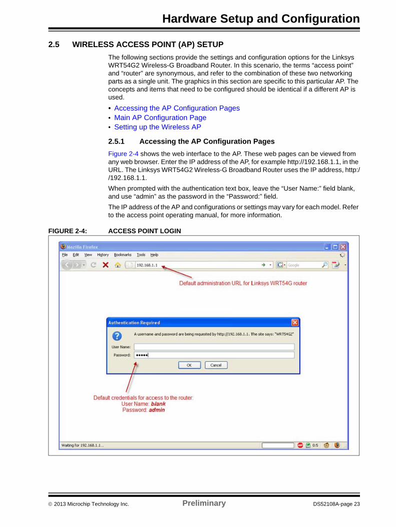
2.5.1 Accessing the AP Configuration Pages
Figure 2-4 shows the web interface to the AP. These web pages can be viewed from any web browser. Enter the IP address of the AP, for example http://192.168.1.1, in the URL. The Linksys WRT54G2 Wireless-G Broadband Router uses the IP address, http://192.168.1.1.
When prompted with the authentication text box, leave the “User Name:” field blank, and use “admin” as the password in the “Password:” field.
The IP address of the AP and configurations or settings may vary for each model. Refer to the access point operating manual, for more information.
FIGURE 2-4: ACCESS POINT LOGIN
2013 Microchip Technology Inc. Preliminary DS52108A-page 23
Microchip MRF24W Getting Started Guide for MRF24WB0MA/B, MRF24WG0MA/B for MLA v5
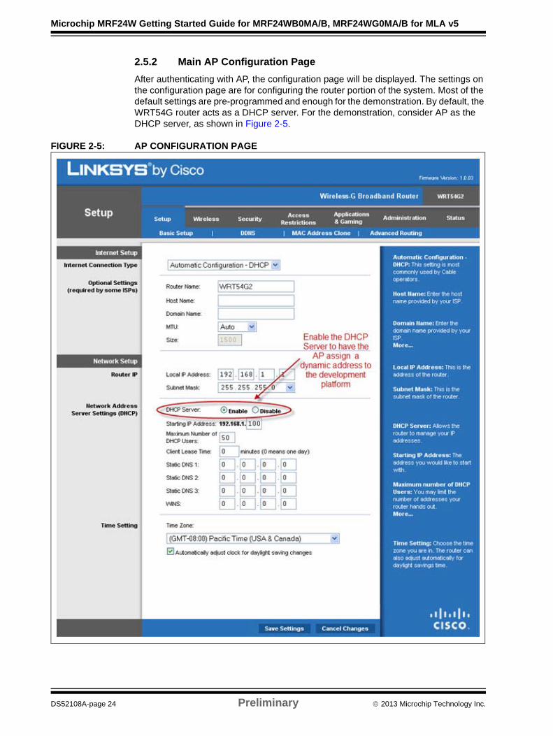
2.5.2 Main AP Configuration Page
After authenticating with AP, the configuration page will be displayed. The settings on the configuration page are for configuring the router portion of the system. Most of the default settings are pre-programmed and enough for the demonstration. By default, the WRT54G router acts as a DHCP server. For the demonstration, consider AP as the DHCP server, as shown in Figure 2-5.
FIGURE 2-5: AP CONFIGURATION PAGE
DS52108A-page 24 Preliminary 2013 Microchip Technology Inc.
Hardware Setup and Configuration
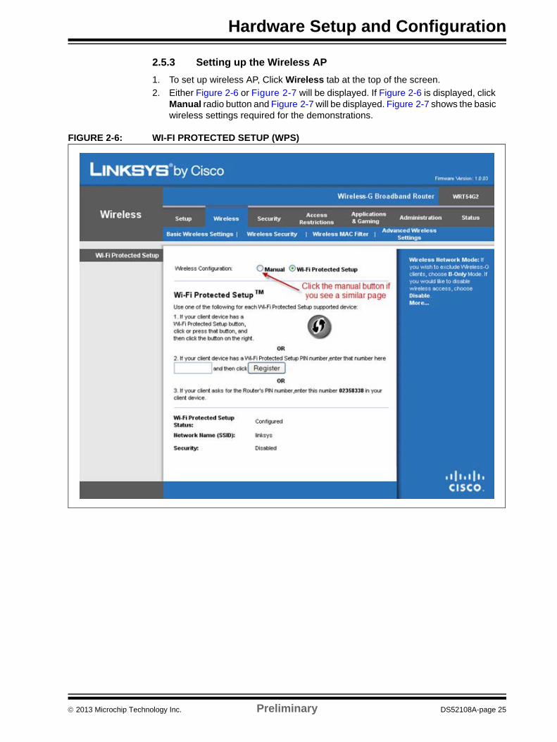
2.5.3 Setting up the Wireless AP
1. To set up wireless AP, Click Wireless tab at the top of the screen.
2. Either Figure 2-6 or Figure 2-7 will be displayed. If Figure 2-6 is displayed, click Manual radio button and Figure 2-7 will be displayed. Figure 2-7 shows the basic wireless settings required for the demonstrations.
FIGURE 2-6: WI-FI PROTECTED SETUP (WPS)
2013 Microchip Technology Inc. Preliminary DS52108A-page 25
Microchip MRF24W Getting Started Guide for MRF24WB0MA/B, MRF24WG0MA/B for MLA v5
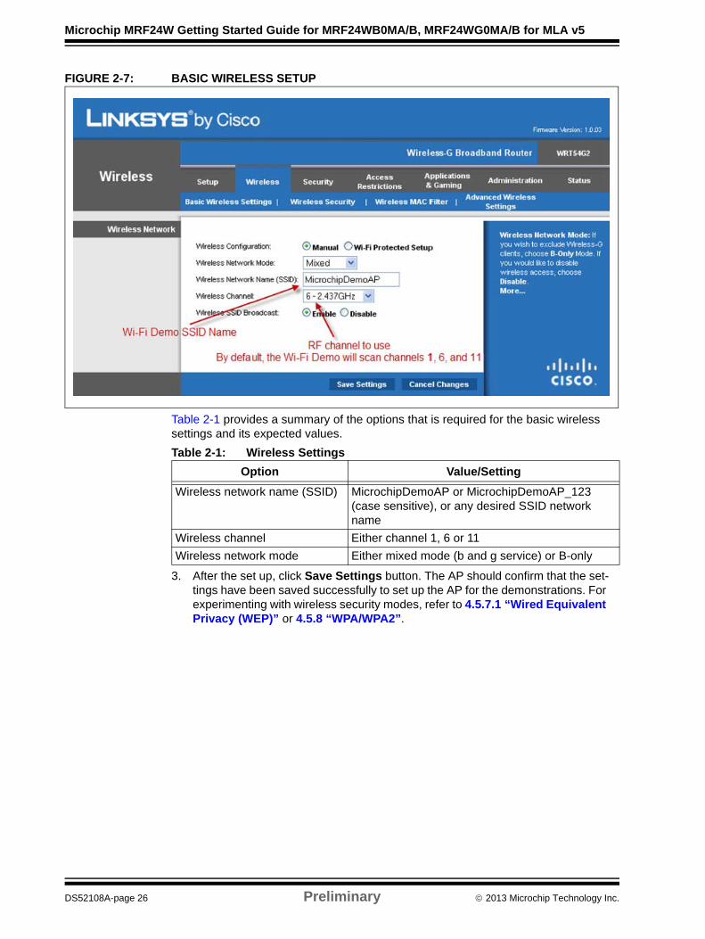
FIGURE 2-7: BASIC WIRELESS SETUP
Table 2-1 provides a summary of the options that is required for the basic wireless settings and its expected values.
3. After the set up, click Save Settings button. The AP should confirm that the set-tings have been saved successfully to set up the AP for the demonstrations. For experimenting with wireless security modes, refer to 4.5.7.1 “Wired Equivalent Privacy (WEP)” or 4.5.8 “WPA/WPA2”.
Table 2-1: Wireless Settings
Option Value/Setting
Wireless network name (SSID) MicrochipDemoAP or MicrochipDemoAP_123 (case sensitive), or any desired SSID network name
Wireless channel Either channel 1, 6 or 11
Wireless network mode Either mixed mode (b and g service) or B-only
DS52108A-page 26 Preliminary 2013 Microchip Technology Inc.
Hardware Setup and Configuration
2.6 SERIAL MONITOR SETUP
The Serial Monitor Setup is applicable for Explorer 16 and PICDEM.Net2 development boards. The MRF24WB0MA/B or MRF24WG0MA/B Wi-Fi® PICtail™ displays and send status information to the serial UART port on the Microchip development board that is useful for debugging. This section provides detailed information on setting up a terminal session to view this output by using “HyperTerminal” as an example. The same approach is used for other serial port monitors such as Tera Term and so on.
2.6.1 To Set up Serial Monitor
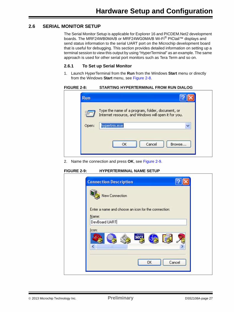
1. Launch HyperTerminal from the Run from the Windows Start menu or directly from the Windows Start menu, see Figure 2-8.
FIGURE 2-8: STARTING HYPERTERMINAL FROM RUN DIALOG
2. Name the connection and press OK, see Figure 2-9.
FIGURE 2-9: HYPERTERMINAL NAME SETUP
2013 Microchip Technology Inc. Preliminary DS52108A-page 27
Microchip MRF24W Getting Started Guide for MRF24WB0MA/B, MRF24WG0MA/B for MLA v5
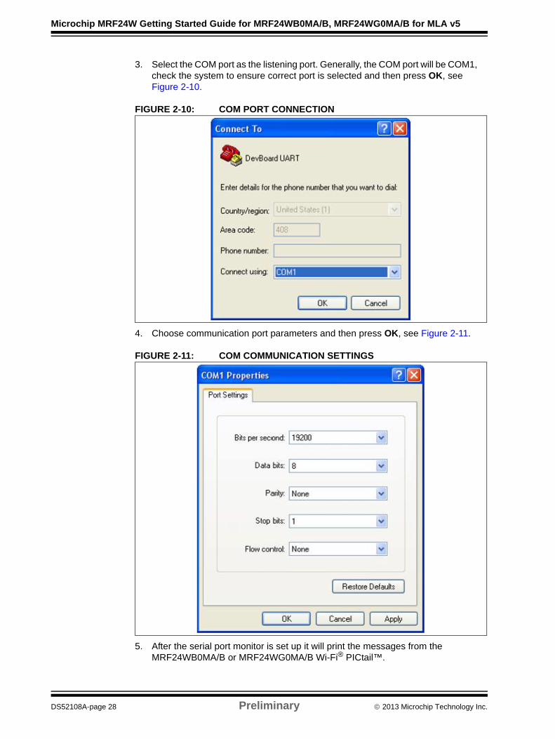
3. Select the COM port as the listening port. Generally, the COM port will be COM1, check the system to ensure correct port is selected and then press OK, see Figure 2-10.
FIGURE 2-10: COM PORT CONNECTION
4. Choose communication port parameters and then press OK, see Figure 2-11.
FIGURE 2-11: COM COMMUNICATION SETTINGS
5. After the serial port monitor is set up it will print the messages from the MRF24WB0MA/B or MRF24WG0MA/B Wi-Fi® PICtail™.
DS52108A-page 28 Preliminary 2013 Microchip Technology Inc.
MICROCHIP MRF24W GETTINGSTARTED GUIDE FOR
MRF24WB0MA/B, MRF24WG0MA/B
FOR MLA V5Chapter 3. Software Setup and Configuration
3.1 SOFTWARE ITEMS TO INSTALL
The following are required to install the software:
• Microchip MPLAB Integrated Development Environment (MPLAB® X IDE)
• Microchip MPLAB® XC compiler (PIC24/32) and Microchip MPLAB C18 Compiler (PIC18)
• Microchip TCP/IP stack installer (which contains the MRF24WB0MA/B or MRF24WG0MA/B Wi-Fi® driver)
3.2 INSTALLING THE MICROCHIP MPLAB® X IDE
The path to the MPLAB X IDE is available on the Microchip web site, see A.2 “Microchip Software”. After downloading the installer, execute the setup file and follow the GUI instructions for installing the MPLAB X IDE on your computer. Restart the computer after the installation.
3.3 INSTALLING THE MICROCHIP MPLAB® XC/C18 COMPILER
Different versions of the MPLAB XC compiler for different PIC microprocessors are available. For PICDEM.net 2 Development Board, the C18 compiler for PIC18 MCUs is required. For Explorer 16 Development Board, either the XC16 compiler for PIC24/dsPIC or the XC32 compiler for PIC32 devices is required.
Microchip offers evaluation copies of the compilers (student versions) that can be downloaded from the Microchip web site, refer to A.2 “Microchip Software”. After downloading the installer, run through the setup to install the compiler on your system.
Note 1: Microchip In-circuit Debugger, for example ICD 3 or REAL ICE™ driver is embedded with the MPLAB X IDE instal lation.
2: The screenshots provide references to older versions of the MPLAB X IDE, and older compiler and TCP/IP stack versions. These screenshots are for visual cues only, and the latest versions should be installed from the Microchip web site.
2013 Microchip Technology Inc. Preliminary DS52108A-page 29
Microchip MRF24W Getting Started Guide for MRF24WB0MA/B, MRF24WG0MA/B for MLA v5
3.4 INSTALLING THE MICROCHIP TCP/IP STACK WITH MRF24WB0MA/B OR MRF24WG0MA/B WI-FI® DRIVER
The TCP/IP stack and MRF24WB0MA/B or MRF24WG0MA/B Wi-Fi® driver is available in two different forms:
• CDROM disc
• Download from Microchip web site (www.microchip.com)
A CDROM disc with the installer is bundled with the development kit provided by MRF24WB0MA/B or MRF24WG0MA/B Wi-Fi® Wireless. Optionally, the installer can be downloaded from the Microchip web site, refer to A.2 “Microchip Software”. It is recommended to download the latest software version from the Microchip web site, which covers latest bug fixes and the best support for current versions of the compilers.
The installer by default installs the stack code, driver, documentation and demonstration project files into versioned directory, where version is denoted by the MLA date, for example, C:\Microchip Solutions v2012-08-22.
3.5 INSTALLING INTERIM CODE RELEASES
User may need to install special interim code releases that are not part of the function-ary code library provided by Microchip and MRF24WB0MA/B or MRF24WG0MA/B. The reasons can be high priority bug fixes, new features that are required by the cus-tomers and so on.
3.5.1 To Install the Interim Code
1. Save any open files in the C:\Microchip Solutions directory and quit the MPLAB X IDE.
2. Open the zip file to view affected directories.
3. Save required work files from this directories to another location.
4. Unzip or copy the directories in the zip file to the C:\Microchip Solutions directory.
5. Restart the MPLAB X IDE to use the codes.
DS52108A-page 30 Preliminary 2013 Microchip Technology Inc.
MICROCHIP MRF24W GETTINGSTARTED GUIDE FOR
MRF24WB0MA/B, MRF24WG0MA/B
FOR MLA V5Chapter 4. Sample Application Demonstrations
The development environment is equipped with three out-of-the-box WiFi demonstrations to showcase the MRF24WB0MA/B or MRF24WG0MA/B Wi-Fi® module. More demonstrations and features may be added in the future.
These demonstrations are illustrated based on Microsoft Windows® OS and the Linksys WRT54G2 Wireless-G Broadband Router. The concepts remain the same for different OS or router.
The following network types (MY_DEFAULT_NETWORK_TYPE) are supported, as indicated in the WF_Config.h file:
• CFG_WF_INFRASTRUCTURE
• CFG_WF_ADHOC
• CFG_WF_P2P (applicable only for MRF24WG0MA/B)
• CFG_WF_SOFT_AP (applicable only for MRF24WG0MA/B)
4.1 BASIC DEMONSTRATION APPLICATIONS
• TCPIP – Demo App
• TCPIP – WiFi Console
• TCP/IP – WiFi EZConfig
Detailed information is available in the Microchip TCPIP Stack Help.chm help file, which is part of the TCP/IP Stack source code releases.
4.1.1 TCPIP – Demo App
A powerful WiFi demonstration that shows a web server that enables you to perform many application level activities such as send and process form data, send emails, upload files and so on. This demonstration highlights many applications that are supported by the Microchip TCP/IP stack and how they can be used with WiFi.
Supported network types:
• CFG_WF_INFRASTRUCTURE
• CFG_WF_ADHOC
• CFG_WF_P2P (applicable only for MRF24WG0MA/B)
In addition, this demonstration is used to showcase the two WPS connection methods:
• WF_SECURITY_WPS_PUSH_BUTTON
• WF_SECURITY_WPS_PIN
Note: SoftAP, WiFi Direct (P2P) and WiFi Protected Setup (WPS) are only sup-ported by stack version v5.42 and newer version.
2013 Microchip Technology Inc. Preliminary DS52108A-page 31
Microchip MRF24W Getting Started Guide for MRF24WB0MA/B, MRF24WG0MA/B for MLA v5
4.1.2 TCPIP – WiFi Console
TCP/IP – WiFi Console is a throughput performance demonstration using a tool called Iperf, which is a commonly used networking test tool. Iperf will allow you to measure the throughput bandwidth on the WiFi link for both receive and transmit.
Supported network types for TCP/IP - WiFi Console:
• CFG_WF_INFRASTRUCTURE
• CFG_WF_ADHOC
• CFG_WF_P2P (applicable only for MRF24WG0MA/B)
4.1.3 TCP/IP – WiFi EZConfig
TCP/IP - WiFi EZConfig demonstration configures an embedded device on a wireless network. It utilizes the web server of the TCP/IP stack and a wireless ad hoc (IBSS) network to allow the user to input the desired network information from a client browser, and then Reset the device to connect to the desired network.
Supported network types:
• CFG_WF_ADHOC
• CFG_WF_SOFT_AP (applicable only for MRF24WG0MA/B)
4.2 WALKTHROUGH AND INSTRUCTIONS ON RUNNING THE DEMONSTRATION
This section consists of the following logical sections:
• Opening Existing Projects
• Hardware Configuration Options
• Compile-Time Configuration Options
• Compiling and Downloading Images
• Running TCP/IP – Demo App
• Running the TCPIP – WiFi Console
• Running the TCPIP – WiFi EZConfig
DS52108A-page 32 Preliminary 2013 Microchip Technology Inc.
Sample Application Demonstrations
4.3 OPENING EXISTING PROJECTS
This section describes the TCP/IP demonstration application running on an Explorer 16 Development Board with a PIC24/32 PIM module installed. The configuration, compile and downloading of the code image to the PIC MCUs is the same for all of the development boards, MCUs and demonstration applications. After starting the MPLAB X IDE, the user can open an existing project.
4.3.1 To Open an Existing Project
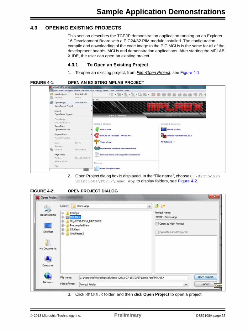
1. To open an existing project, from File>Open Project, see Figure 4-1.
FIGURE 4-1: OPEN AN EXISTING MPLAB PROJECT
2. Open Project dialog box is displayed. In the “File name”, choose C:\Microchip Solutions\TCPIP\Demo App to display folders, see Figure 4-2.
FIGURE 4-2: OPEN PROJECT DIALOG
3. Click MPLAB.X folder, and then click Open Project to open a project.
2013 Microchip Technology Inc. Preliminary DS52108A-page 33

Microchip MRF24W Getting Started Guide for MRF24WB0MA/B, MRF24WG0MA/B for MLA v5
4.4 HARDWARE CONFIGURATION OPTIONS
Depending on the development board used, the relevant hardware profile header file must be changed to match the configuration of the slot on which the PICtail is plugged into. For Explorer 16 with XC32 configurations, the hardware profile header file is HWP EX16_MRF24W XC32.h. Ensure that the selected SPI option (MRF24W_IN_SPI1 or MRF24W_IN_SPI2) matches the development board’s setup. Figure 4-3 shows the location of the required changes.
Required hardware profile header files for the development boards:
• PICDEM.net 2 Development Boards, only one configuration for the PICtail and MRF24W_IN_SPI1 to be defined
• Explorer 16 Development Board using PIC24FJ128GA010, use either MRF24W_IN_SPI1 or MRF24W_IN_SPI2; if it matches the location that the PIC-tail is plugged into the card edge connector (SPI1 refers to the upper location, closest to the LCD)
• dsPIC33FJ256GP710, this Plug-In Module (PIM) works only when MRF24W_IN_SPI2 is defined and the PICtail is plugged into the middle card edge socket
FIGURE 4-3: HWP EX16_MRF24W XC32.H SPI OPTIONS
DS52108A-page 34 Preliminary 2013 Microchip Technology Inc.
Sample Application Demonstrations
4.5 COMPILE-TIME CONFIGURATION OPTIONS
The following files contain most of the compile-time options for the demonstrations:
• TCPIP MRF24W.h, located in the Configs sub folder within individual demon-strations. For example, \TCPIP\Demo App\Configs\TCPIP MRF24W.h.
• WF_Config.h, located within the individual demonstrations. For example: \TCPIP\Demo App\WF_Config.h
These files can be viewed within the MPLAB X IDE using the file navigator.
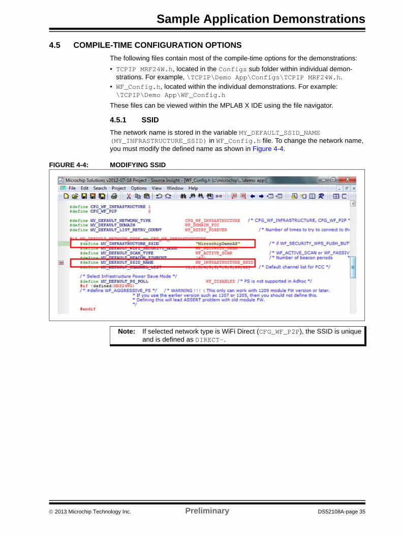
4.5.1 SSID
The network name is stored in the variable MY_DEFAULT_SSID_NAME (MY_INFRASTRUCTURE_SSID) in WF_Config.h file. To change the network name, you must modify the defined name as shown in Figure 4-4.
FIGURE 4-4: MODIFYING SSID
Note: If selected network type is WiFi Direct (CFG_WF_P2P), the SSID is unique and is defined as DIRECT-.
2013 Microchip Technology Inc. Preliminary DS52108A-page 35
Microchip MRF24W Getting Started Guide for MRF24WB0MA/B, MRF24WG0MA/B for MLA v5
4.5.2 Static IP Address
By default, the demonstrations use DHCP and rely on the DHCP server in the AP or router to give the development board an IP address on the network.
4.5.2.1 TO ENABLE THE USE OF A STATIC IP ADDRESS
1. The selected static IP address must be on the same subnet as the AP. By default, the Linksys WRT54G manages IP addresses on the subnet 192.168.1.x (192.168.1.1 is for AP). The IP address above 192.168.1.100 are dynamically managed by the DHCP server. Therefore, ideal to assign a unique static IP address in the range of 192.168.1.2 – 192.168.1.99.
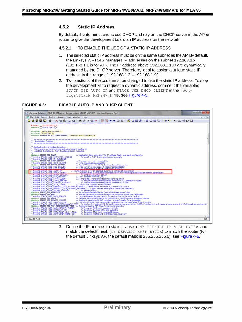
2. Two sections of the code must be changed to use the static IP address. To stop the development kit to request a dynamic address, comment the variables STACK_USE_AUTO_IP and STACK_USE_DHCP_CLIENT in the \con-figs\TCPIP MRF24W.h file, see Figure 4-5.
FIGURE 4-5: DISABLE AUTO IP AND DHCP CLIENT
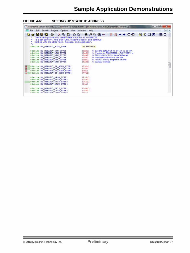
3. Define the IP address to statically use in MY_DEFAULT_IP_ADDR_BYTEx, and match the default mask (MY_DEFAULT_MASK_BYTEx) to match the router (for the default Linksys AP, the default mask is 255.255.255.0), see Figure 4-6.
DS52108A-page 36 Preliminary 2013 Microchip Technology Inc.
Sample Application Demonstrations
FIGURE 4-6: SETTING UP STATIC IP ADDRESS
2013 Microchip Technology Inc. Preliminary DS52108A-page 37
Microchip MRF24W Getting Started Guide for MRF24WB0MA/B, MRF24WG0MA/B for MLA v5
4.5.3 MAC Address
In the system there are three sources for the MAC address:
• Built-in MAC address on the MRF24WB0MA/B or MRF24WG0MA/B WiFi® mod-ule that is preprogrammed from the factory with the MRF24WB0MA/B or MRF24WG0MA/B Wi-Fi® OUI
• Programmed code image
• Value that is stored in the EEPROM
At run-time, a data structure is created in RAM, which stores the valid MAC address (amongst other information) to be used for that session. The code will check if a valid data structure is located in the EEPROM. If the valid data structure exists in EEPROM, then those values will be used, overriding what is programmed inside the chip and/or programmed in the code at compile-time.
If no data structure exists in the EEPROM, then the value that is stored in the \configs\TCPIP MRF24W.h file will be used. If the value in the source code is 00:04:A3:00:00:00, then it indicates to the program that the value that has been preprogrammed in the MRF24WB0MA/B or MRF24WG0MA/B Wi-Fi® module should be used. Otherwise, the value that is placed into the MY_DEFAULT_MAC_BYTEx will be used. Additionally, if no valid data structure exists in the EEPROM, the new value will be programmed and stored to the EEPROM for the future use.
EEPROM has the highest priority. Therefore, if a value for the MAC address is programmed to the EEPROM, no other value can override it. To change the values, EEPROM must be erased. Refer to the instructions specified in 5.3 “Erasing EEPROM”.
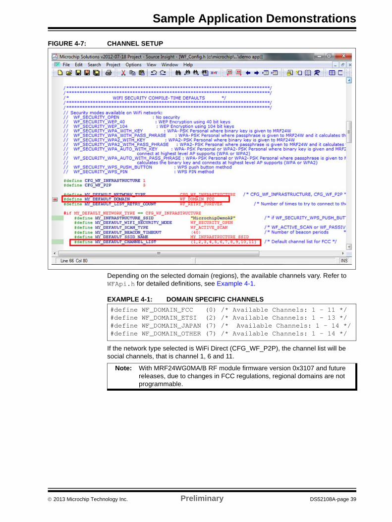
4.5.4 Channel Configuration
802.11b and 802.11g divide the 2.4 GHz spectrum into 14 channels, from channel 1 through channel 14. The bandwidth of each channel is 20 MHz which means that chan-nels may overlap. The commonly used non overlapping channels and social channels are channels 1, 6 and 11.
The RF channel that is used can be configured at compile-time. The following two inter-related options control channels data transmission:
• Regulatory domain, as specified by MY_DEFAULT_DOMAIN. Different domains have different channel offerings, hence it must match with the intended country and channel
• Channel scan list (MY_DEFAULT_CHANNEL_LIST), which is an array of chan-nels that will be scanned for RF activity.
As illustrated in Figure 4-7, the domain is set to FCC and there are 11 total channels in the scan list (1, 2, 3, 4, 5, 6, 7, 8, 9, 10 and 11).
Note: If more channels to scan, it takes longer time to connect.
DS52108A-page 38 Preliminary 2013 Microchip Technology Inc.
Sample Application Demonstrations
FIGURE 4-7: CHANNEL SETUP
Depending on the selected domain (regions), the available channels vary. Refer to WFApi.h for detailed definitions, see Example 4-1.
EXAMPLE 4-1: DOMAIN SPECIFIC CHANNELS
If the network type selected is WiFi Direct (CFG_WF_P2P), the channel list will be social channels, that is channel 1, 6 and 11.
Note: With MRF24WG0MA/B RF module firmware version 0x3107 and future releases, due to changes in FCC regulations, regional domains are not programmable.
#define WF_DOMAIN_FCC (0) /* Available Channels: 1 - 11 */#define WF_DOMAIN_ETSI (2) /* Available Channels: 1 - 13 */#define WF_DOMAIN_JAPAN (7) /* Available Channels: 1 - 14 */#define WF_DOMAIN_OTHER (7) /* Available Channels: 1 - 14 */
2013 Microchip Technology Inc. Preliminary DS52108A-page 39
Microchip MRF24W Getting Started Guide for MRF24WB0MA/B, MRF24WG0MA/B for MLA v5
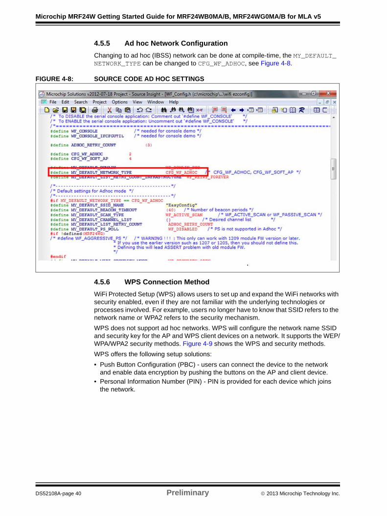
4.5.5 Ad hoc Network Configuration
Changing to ad hoc (IBSS) network can be done at compile-time, the MY_DEFAULT_ NETWORK_TYPE can be changed to CFG_WF_ADHOC, see Figure 4-8.
FIGURE 4-8: SOURCE CODE AD HOC SETTINGS
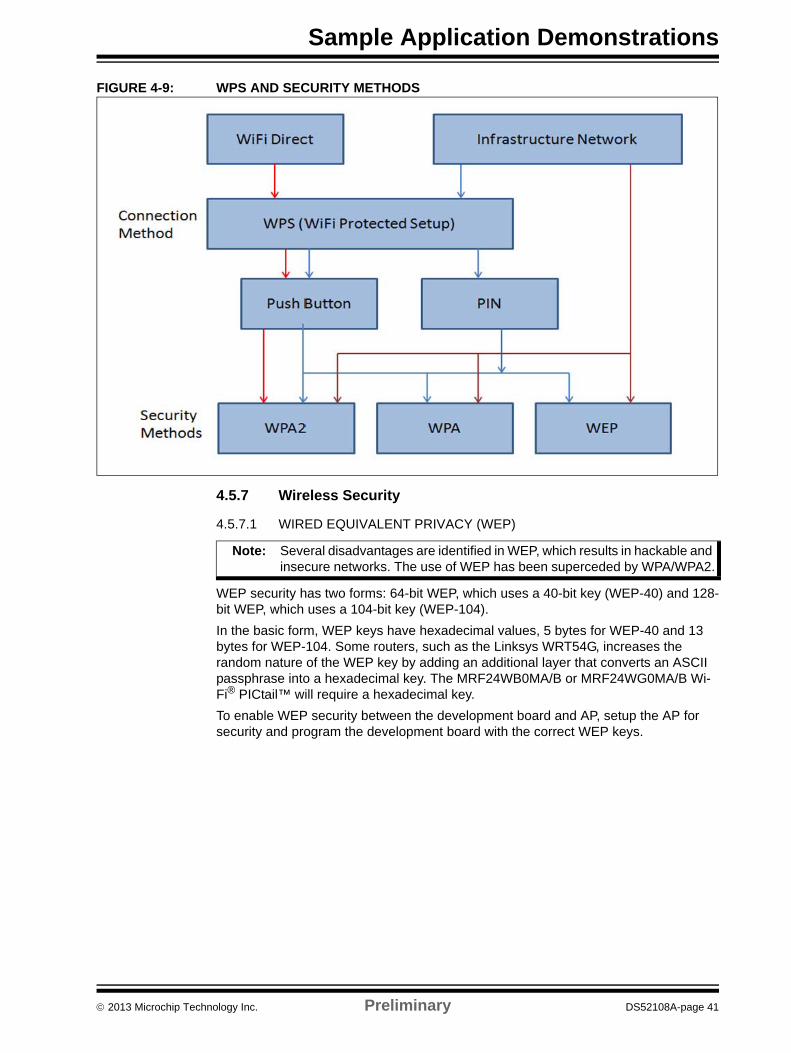
4.5.6 WPS Connection Method
WiFi Protected Setup (WPS) allows users to set up and expand the WiFi networks with security enabled, even if they are not familiar with the underlying technologies or processes involved. For example, users no longer have to know that SSID refers to the network name or WPA2 refers to the security mechanism.
WPS does not support ad hoc networks. WPS will configure the network name SSID and security key for the AP and WPS client devices on a network. It supports the WEP/WPA/WPA2 security methods. Figure 4-9 shows the WPS and security methods.
WPS offers the following setup solutions:
• Push Button Configuration (PBC) - users can connect the device to the network and enable data encryption by pushing the buttons on the AP and client device.
• Personal Information Number (PIN) - PIN is provided for each device which joins the network.
DS52108A-page 40 Preliminary 2013 Microchip Technology Inc.
Sample Application Demonstrations
FIGURE 4-9: WPS AND SECURITY METHODS
4.5.7 Wireless Security
4.5.7.1 WIRED EQUIVALENT PRIVACY (WEP)
WEP security has two forms: 64-bit WEP, which uses a 40-bit key (WEP-40) and 128-bit WEP, which uses a 104-bit key (WEP-104).
In the basic form, WEP keys have hexadecimal values, 5 bytes for WEP-40 and 13 bytes for WEP-104. Some routers, such as the Linksys WRT54G, increases the random nature of the WEP key by adding an additional layer that converts an ASCII passphrase into a hexadecimal key. The MRF24WB0MA/B or MRF24WG0MA/B Wi-Fi® PICtail™ will require a hexadecimal key.
To enable WEP security between the development board and AP, setup the AP for security and program the development board with the correct WEP keys.
Note: Several disadvantages are identified in WEP, which results in hackable and insecure networks. The use of WEP has been superceded by WPA/WPA2.
2013 Microchip Technology Inc. Preliminary DS52108A-page 41
Microchip MRF24W Getting Started Guide for MRF24WB0MA/B, MRF24WG0MA/B for MLA v5
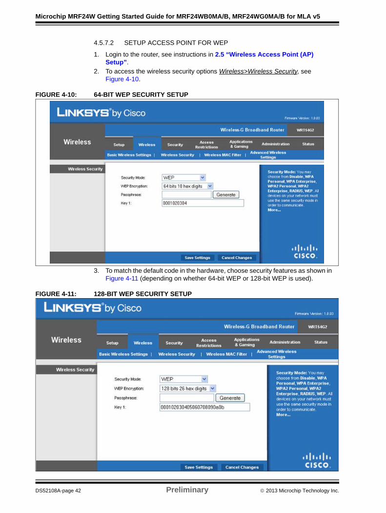
4.5.7.2 SETUP ACCESS POINT FOR WEP
1. Login to the router, see instructions in 2.5 “Wireless Access Point (AP) Setup”.
2. To access the wireless security options Wireless>Wireless Security, see Figure 4-10.
FIGURE 4-10: 64-BIT WEP SECURITY SETUP
3. To match the default code in the hardware, choose security features as shown in Figure 4-11 (depending on whether 64-bit WEP or 128-bit WEP is used).
FIGURE 4-11: 128-BIT WEP SECURITY SETUP
DS52108A-page 42 Preliminary 2013 Microchip Technology Inc.
Sample Application Demonstrations
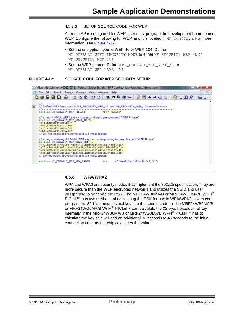
4.5.7.3 SETUP SOURCE CODE FOR WEP
After the AP is configured for WEP, user must program the development board to use WEP. Configure the following for WEP, and it is located in WF_Config.h. For more information, see Figure 4-12.
• Set the encryption type to WEP-40 or WEP-104. Define MY_DEFAULT_WIFI_SECURITY_MODE to either WF_SECURITY_WEP_40 or WF_SECURITY_WEP_104
• Set the WEP phrase. Refer to MY_DEFAULT_WEP_KEYS_40 or MY_DEFAULT_WEP_KEYS_104.
FIGURE 4-12: SOURCE CODE FOR WEP SECURITY SETUP
4.5.8 WPA/WPA2
WPA and WPA2 are security modes that implement the 802.11i specification. They are more secure than the WEP encrypted networks and utilizes the SSID and user passphrase to generate the PSK. The MRF24WB0MA/B or MRF24WG0MA/B Wi-Fi® PICtail™ has two methods of calculating the PSK for use in WPA/WPA2. Users can program the 32-byte hexadecimal key into the source code, or the MRF24WB0MA/B or MRF24WG0MA/B Wi-Fi® PICtail™ can calculate the 32-byte hexadecimal key internally. If the MRF24WB0MA/B or MRF24WG0MA/B Wi-Fi® PICtail™ has to calculate the key, this will add an additional 30 seconds to 45 seconds to the initial connection time, as the chip calculates the value.
2013 Microchip Technology Inc. Preliminary DS52108A-page 43
Microchip MRF24W Getting Started Guide for MRF24WB0MA/B, MRF24WG0MA/B for MLA v5
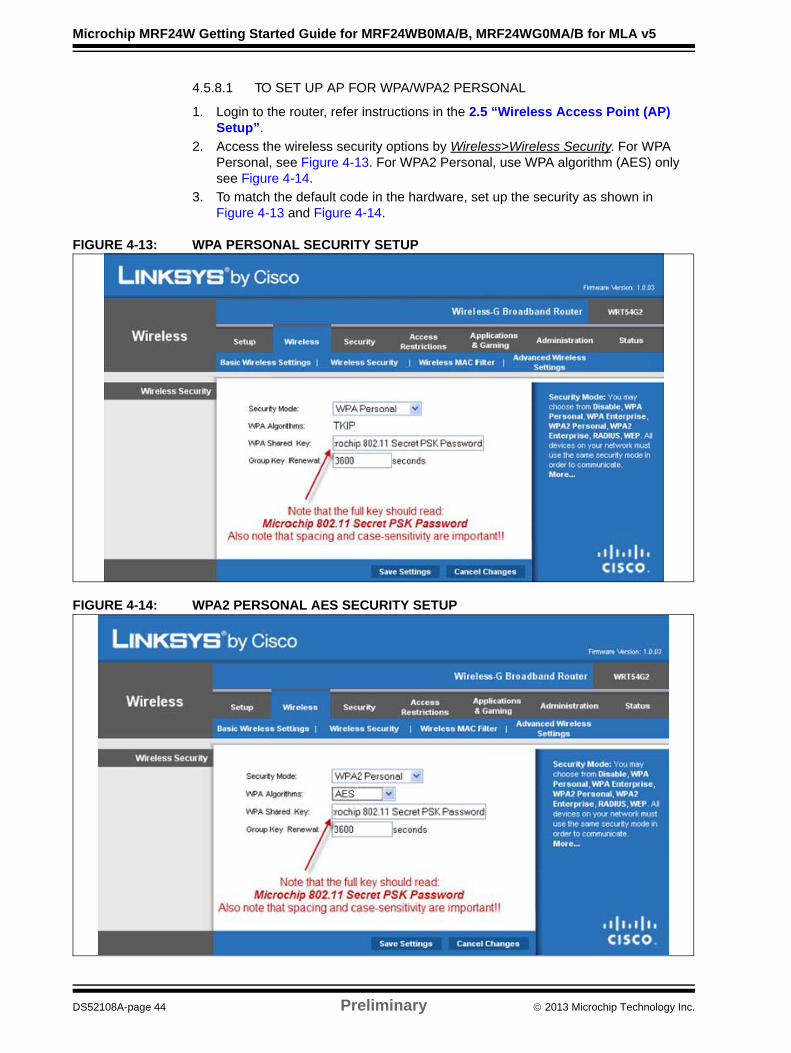
4.5.8.1 TO SET UP AP FOR WPA/WPA2 PERSONAL
1. Login to the router, refer instructions in the 2.5 “Wireless Access Point (AP) Setup”.
2. Access the wireless security options by Wireless>Wireless Security. For WPA Personal, see Figure 4-13. For WPA2 Personal, use WPA algorithm (AES) only see Figure 4-14.
3. To match the default code in the hardware, set up the security as shown in Figure 4-13 and Figure 4-14.
FIGURE 4-13: WPA PERSONAL SECURITY SETUP
FIGURE 4-14: WPA2 PERSONAL AES SECURITY SETUP
DS52108A-page 44 Preliminary 2013 Microchip Technology Inc.

Sample Application Demonstrations
4.5.9 Setup Source Code for WPA/WPA2
The MRF24WB0MA/B or MRF24WG0MA/B Wi-Fi® PICtail™ has the following two approaches to run WPA/WPA2 security:
• On-the-fly PSK Calculation - The straight forward approach to supply the passphrase. The PIC18/24/32 or PICtail will calculate the PSK based on the SSID and the supplied passphrase. Due to the computationally intensive nature of this operation, this will take approximately 30 seconds to 45 seconds to complete.
• Pre generated PSK - This approach is to provide the 32 byte PSK, and user can directly plug this value into the source code.
The following section describes setting up and using both the preceding approaches:
4.5.9.1 ON-THE-FLY PSK CALCULATION
Only two pieces of information required to enable the MRF24WB0MA/B or MRF24WG0MA/B Wi-Fi® PICtail™ to calculate the PSK and use that for the encryption process, see Figure 4-15.
Define MY_DEFAULT_WIFI_SECURITY_MODE to be WF_SECURITY_WPA_WITH_PASS_PHRASE or WF_SECURITY_WPA2_WITH_PASS_PHRASE.
Define MY_DEFAULT_PSK_PHRASE.
FIGURE 4-15: SOURCE CODE CALCULATE PSK SETUP
Note that passphrase is case sensitive and spacing does matter.
2013 Microchip Technology Inc. Preliminary DS52108A-page 45
Microchip MRF24W Getting Started Guide for MRF24WB0MA/B, MRF24WG0MA/B for MLA v5
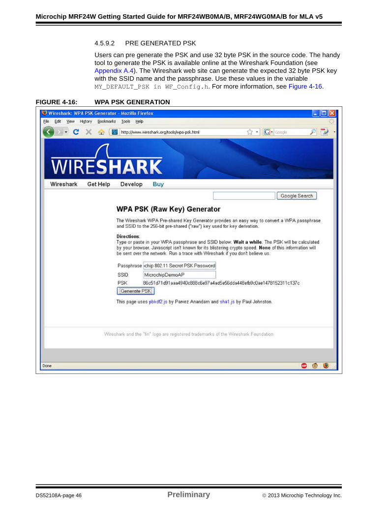
4.5.9.2 PRE GENERATED PSK
Users can pre generate the PSK and use 32 byte PSK in the source code. The handy tool to generate the PSK is available online at the Wireshark Foundation (see Appendix A.4). The Wireshark web site can generate the expected 32 byte PSK key with the SSID name and the passphrase. Use these values in the variable MY_DEFAULT_PSK in WF_Config.h. For more information, see Figure 4-16.
FIGURE 4-16: WPA PSK GENERATION
DS52108A-page 46 Preliminary 2013 Microchip Technology Inc.
Sample Application Demonstrations
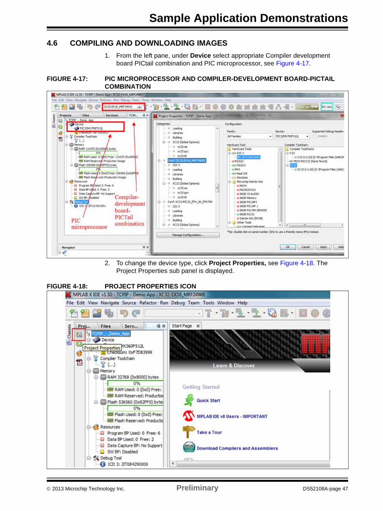
4.6 COMPILING AND DOWNLOADING IMAGES
1. From the left pane, under Device select appropriate Compiler development board PICtail combination and PIC microprocessor, see Figure 4-17.
FIGURE 4-17: PIC MICROPROCESSOR AND COMPILER-DEVELOPMENT BOARD-PICTAIL COMBINATION
2. To change the device type, click Project Properties, see Figure 4-18. The Project Properties sub panel is displayed.
FIGURE 4-18: PROJECT PROPERTIES ICON
2013 Microchip Technology Inc. Preliminary DS52108A-page 47
Microchip MRF24W Getting Started Guide for MRF24WB0MA/B, MRF24WG0MA/B for MLA v5
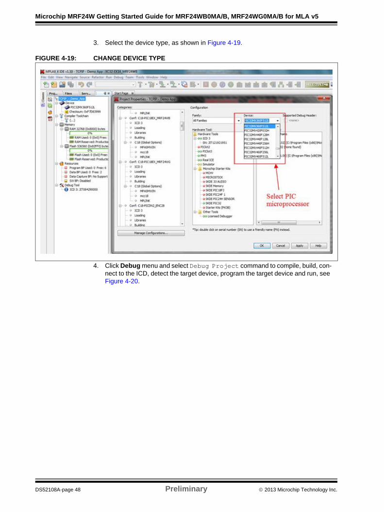
3. Select the device type, as shown in Figure 4-19.
FIGURE 4-19: CHANGE DEVICE TYPE
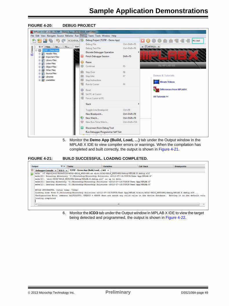
4. Click Debug menu and select Debug Project command to compile, build, con-nect to the ICD, detect the target device, program the target device and run, see Figure 4-20.
DS52108A-page 48 Preliminary 2013 Microchip Technology Inc.
Sample Application Demonstrations
FIGURE 4-20: DEBUG PROJECT
5. Monitor the Demo App (Build, Load, …) tab under the Output window in the MPLAB X IDE to view compiler errors or warnings. When the compilation has completed and built correctly, the output is shown in Figure 4-21.
FIGURE 4-21: BUILD SUCCESSFUL. LOADING COMPLETED.
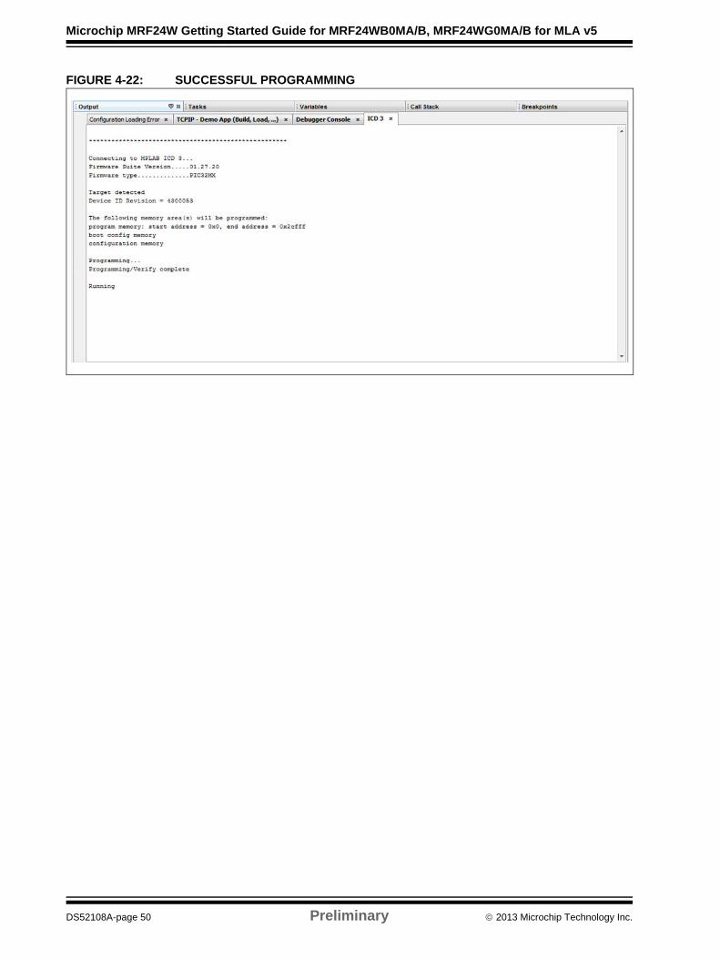
6. Monitor the ICD3 tab under the Output window in MPLAB X IDE to view the target being detected and programmed, the output is shown in Figure 4-22.
2013 Microchip Technology Inc. Preliminary DS52108A-page 49
Microchip MRF24W Getting Started Guide for MRF24WB0MA/B, MRF24WG0MA/B for MLA v5
FIGURE 4-22: SUCCESSFUL PROGRAMMING
DS52108A-page 50 Preliminary 2013 Microchip Technology Inc.

Sample Application Demonstrations
4.7 RUNNING TCP/IP – DEMO APP
This is applicable only for Explorer 16 and PICDEM.net2 Development Boards as the PIC32 starter kit does not use the EEPROM. Due to this, you may notice situations where you have made changes in the code that are not reflected during the demonstration (for example, you changed the SSID name, but do not see it is being used), and user must erase the EEPROM, refer to 5.3 “Erasing EEPROM”.
For the first time demonstration, perform these actions. The user must setup hardware and software before the WiFi demonstration.
1. Download web server code into the EEPROM of the development board. To download web server code, from the browser navigate to a special page that will allow you to upload image files. More information on uploading image files are provided in the later section. It is recommended to define MY_DEFAULT_WIFI_SECURITY_MODE as WF_SECURITY_OPEN.
2. After the development board is connected to the AP (or it has created the net-work in Ad hoc mode), the LCD panel will display the IP address that is being used. Alternately, the serial output should display the same information.
4.7.1 Network Type: CFG_WF_INFRASTRUCTURE
1. CFG_WF_INFRASTRUCTURE is the default network type with the MLA release. Ensure that SSID and Security mode is set to match with the APs configurations. In the WF_Config.h, perform these actions:
a) Define the MY_DEFAULT_NETWORK_TYPE as CFG_WF_INFRASTRUCTURE.
b) Define the MY_DEFAULT_WIFI_SECURITY_MODE as WF_SECURITY_OPEN.
c) Define the MY_DEFAULT_SSID_NAME to be same as the AP or router’s SSID.
FIGURE 4-23: INFRASTRUCTURE NETWORK ENVIRONMENT SETUP
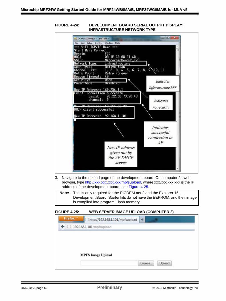
2. After the development board is connected to the AP, the LCD panel displays the IP address that is being used. Alternately, the serial output should display similar informations, see Figure 4-24.
2013 Microchip Technology Inc. Preliminary DS52108A-page 51
Microchip MRF24W Getting Started Guide for MRF24WB0MA/B, MRF24WG0MA/B for MLA v5
FIGURE 4-24: DEVELOPMENT BOARD SERIAL OUTPUT DISPLAY: INFRASTRUCTURE NETWORK TYPE
3. Navigate to the upload page of the development board. On computer 2s web browser, type http://xxx.xxx.xxx.xxx/mpfsupload, where xxx.xxx.xxx.xxx is the IP address of the development board, see Figure 4-25.
FIGURE 4-25: WEB SERVER IMAGE UPLOAD (COMPUTER 2)
Note: This is only required for the PICDEM.net 2 and the Explorer 16 Development Board. Starter kits do not have the EEPROM, and their image is compiled into program Flash memory.
DS52108A-page 52 Preliminary 2013 Microchip Technology Inc.
Sample Application Demonstrations
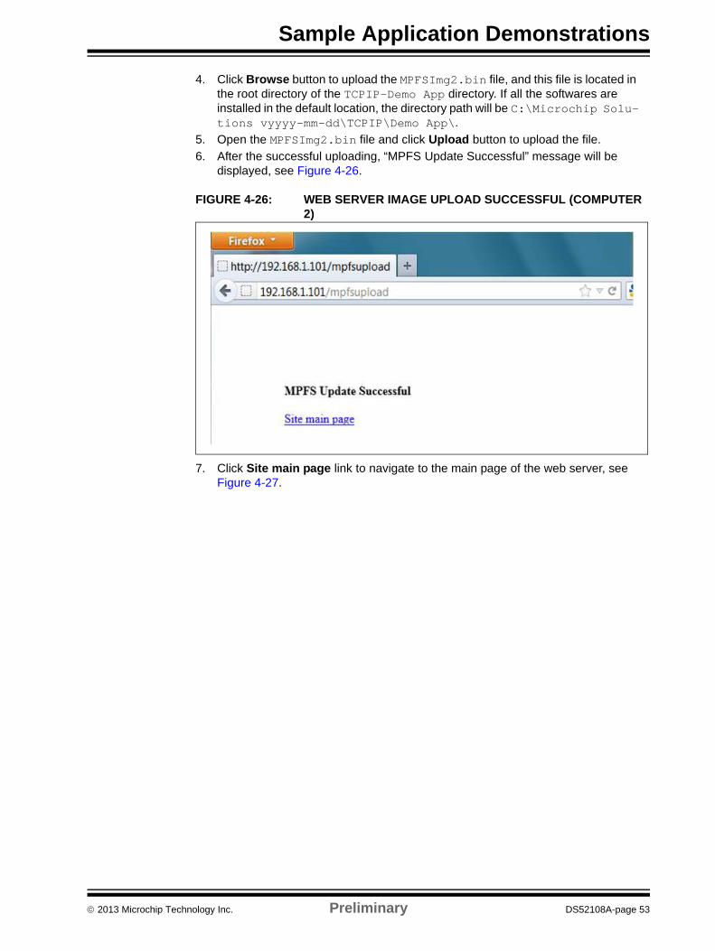
4. Click Browse button to upload the MPFSImg2.bin file, and this file is located in the root directory of the TCPIP-Demo App directory. If all the softwares are installed in the default location, the directory path will be C:\Microchip Solu-tions vyyyy-mm-dd\TCPIP\Demo App\.
5. Open the MPFSImg2.bin file and click Upload button to upload the file.
6. After the successful uploading, “MPFS Update Successful” message will be displayed, see Figure 4-26.
FIGURE 4-26: WEB SERVER IMAGE UPLOAD SUCCESSFUL (COMPUTER 2)
7. Click Site main page link to navigate to the main page of the web server, see Figure 4-27.
2013 Microchip Technology Inc. Preliminary DS52108A-page 53

Microchip MRF24W Getting Started Guide for MRF24WB0MA/B, MRF24WG0MA/B for MLA v5
FIGURE 4-27: TCPIP – DEMO APPLICATION (COMPUTER 2)
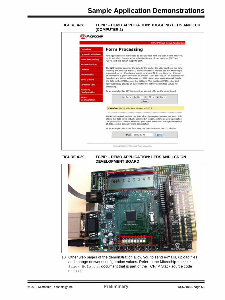
8. The TCP/IP WiFi demonstration application enable users to understand features and applications that are available with the Microchip TCP/IP stack, and how it can be used on wireless medium. From the web main page, user can interact with the development board hardware to toggle LEDs, push buttons and change potentiometer values. For example, from the Form Processing page, user can select the LEDs to be turned ON or OFF by clicking Save button.
9. On the LCD, enter “Test 1 2 3 3 4 5” and click Save button. The respective LEDs on the development board being configured as programmed and the LCD on the development board displays “Test 1 2 3 3 4 5”, see Figure 4-28 and Figure 4-29.
DS52108A-page 54 Preliminary 2013 Microchip Technology Inc.
Sample Application Demonstrations
FIGURE 4-28: TCPIP – DEMO APPLICATION: TOGGLING LEDS AND LCD (COMPUTER 2)
FIGURE 4-29: TCPIP – DEMO APPLICATION: LEDS AND LCD ON DEVELOPMENT BOARD
10. Other web pages of the demonstration allow you to send e-mails, upload files and change network configuration values. Refer to the Microchip TCP/IP Stack Help.chm document that is part of the TCP/IP Stack source code release.
2013 Microchip Technology Inc. Preliminary DS52108A-page 55
Microchip MRF24W Getting Started Guide for MRF24WB0MA/B, MRF24WG0MA/B for MLA v5
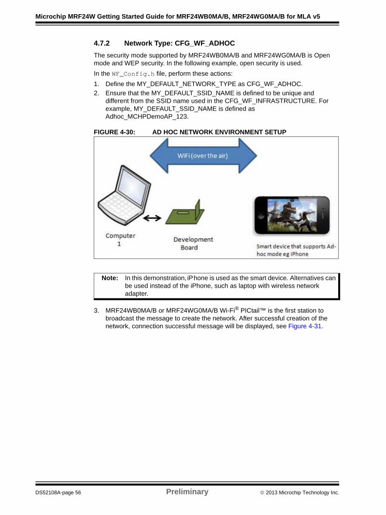
4.7.2 Network Type: CFG_WF_ADHOC
The security mode supported by MRF24WB0MA/B and MRF24WG0MA/B is Open mode and WEP security. In the following example, open security is used.
In the WF_Config.h file, perform these actions:
1. Define the MY_DEFAULT_NETWORK_TYPE as CFG_WF_ADHOC.
2. Ensure that the MY_DEFAULT_SSID_NAME is defined to be unique and different from the SSID name used in the CFG_WF_INFRASTRUCTURE. For example, MY_DEFAULT_SSID_NAME is defined as Adhoc_MCHPDemoAP_123.
FIGURE 4-30: AD HOC NETWORK ENVIRONMENT SETUP
3. MRF24WB0MA/B or MRF24WG0MA/B Wi-Fi® PICtail™ is the first station to broadcast the message to create the network. After successful creation of the network, connection successful message will be displayed, see Figure 4-31.
Note: In this demonstration, iPhone is used as the smart device. Alternatives can be used instead of the iPhone, such as laptop with wireless network adapter.
DS52108A-page 56 Preliminary 2013 Microchip Technology Inc.

Sample Application Demonstrations
FIGURE 4-31: DEVELOPMENT BOARD SERIAL DISPLAY: AD HOC NETWORK TYPE
4. After the development board is connected to another device, the LCD panel will display new IP address, see Figure 4-32. Alternately, the serial output also displays similar information, see Figure 4-31.
FIGURE 4-32: TCPIP – DEMO APPLICATION: LEDS AND LCD ON DEVELOPMENT BOARD
2013 Microchip Technology Inc. Preliminary DS52108A-page 57

Microchip MRF24W Getting Started Guide for MRF24WB0MA/B, MRF24WG0MA/B for MLA v5
5. On the smart device, select the menu settings to view the WiFi networks detected, see Figure 4-33.
FIGURE 4-33: WIFI NETWORKS DETECTED ON SMART DEVICE
6. Click on the ad hoc network SSID to connect to this ad hoc network, as shown in Figure 4-34.
FIGURE 4-34: SELECT AD HOC NETWORK ON SMART DEVICE
DS52108A-page 58 Preliminary 2013 Microchip Technology Inc.

Sample Application Demonstrations
7. After connection to this ad hoc network is established, user can enter IP address of the ad hoc network (for example, 169.254.52.38) on the smart device’s web browser. The demonstration is similar to the infrastructure network type. For example, when user presses any of the buttons (S1 through S4) on the development board, the web page will display the same buttons being pressed, see Figure 4-35.
FIGURE 4-35: WEB BROWSER ON SMART DEVICE (AD HOC BSS)
2013 Microchip Technology Inc. Preliminary DS52108A-page 59
Microchip MRF24W Getting Started Guide for MRF24WB0MA/B, MRF24WG0MA/B for MLA v5
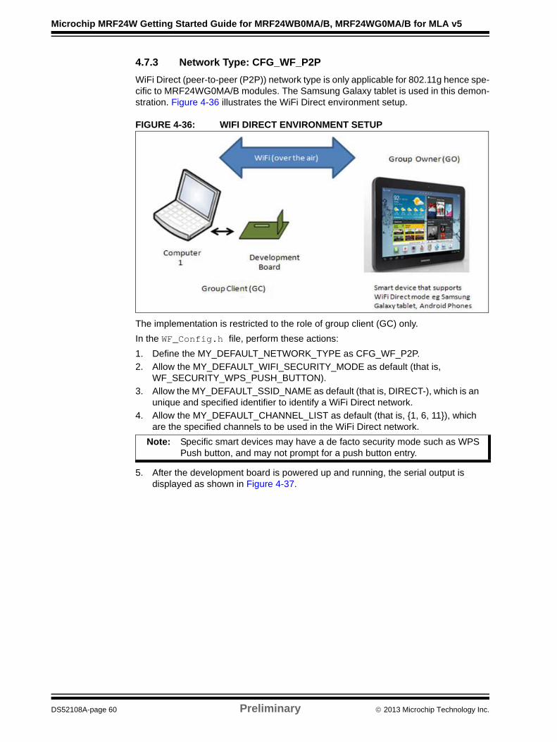
4.7.3 Network Type: CFG_WF_P2P
WiFi Direct (peer-to-peer (P2P)) network type is only applicable for 802.11g hence spe-cific to MRF24WG0MA/B modules. The Samsung Galaxy tablet is used in this demon-stration. Figure 4-36 illustrates the WiFi Direct environment setup.
FIGURE 4-36: WIFI DIRECT ENVIRONMENT SETUP
The implementation is restricted to the role of group client (GC) only.
In the WF_Config.h file, perform these actions:
1. Define the MY_DEFAULT_NETWORK_TYPE as CFG_WF_P2P.
2. Allow the MY_DEFAULT_WIFI_SECURITY_MODE as default (that is, WF_SECURITY_WPS_PUSH_BUTTON).
3. Allow the MY_DEFAULT_SSID_NAME as default (that is, DIRECT-), which is an unique and specified identifier to identify a WiFi Direct network.
4. Allow the MY_DEFAULT_CHANNEL_LIST as default (that is, {1, 6, 11}), which are the specified channels to be used in the WiFi Direct network.
5. After the development board is powered up and running, the serial output is displayed as shown in Figure 4-37.
Note: Specific smart devices may have a de facto security mode such as WPS Push button, and may not prompt for a push button entry.
DS52108A-page 60 Preliminary 2013 Microchip Technology Inc.
Sample Application Demonstrations
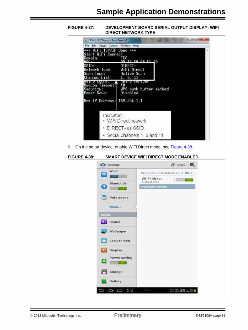
FIGURE 4-37: DEVELOPMENT BOARD SERIAL OUTPUT DISPLAY: WIFI DIRECT NETWORK TYPE
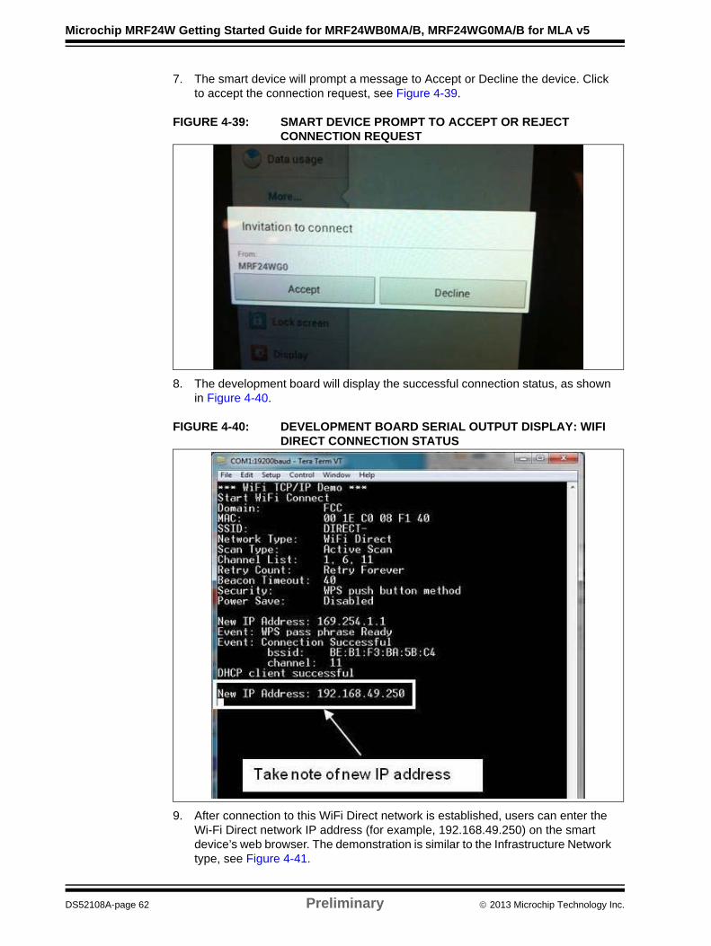
6. On the smart device, enable WiFi Direct mode, see Figure 4-38.
FIGURE 4-38: SMART DEVICE WIFI DIRECT MODE ENABLED
2013 Microchip Technology Inc. Preliminary DS52108A-page 61
Microchip MRF24W Getting Started Guide for MRF24WB0MA/B, MRF24WG0MA/B for MLA v5
7. The smart device will prompt a message to Accept or Decline the device. Click to accept the connection request, see Figure 4-39.
FIGURE 4-39: SMART DEVICE PROMPT TO ACCEPT OR REJECT CONNECTION REQUEST
8. The development board will display the successful connection status, as shown in Figure 4-40.
FIGURE 4-40: DEVELOPMENT BOARD SERIAL OUTPUT DISPLAY: WIFI DIRECT CONNECTION STATUS
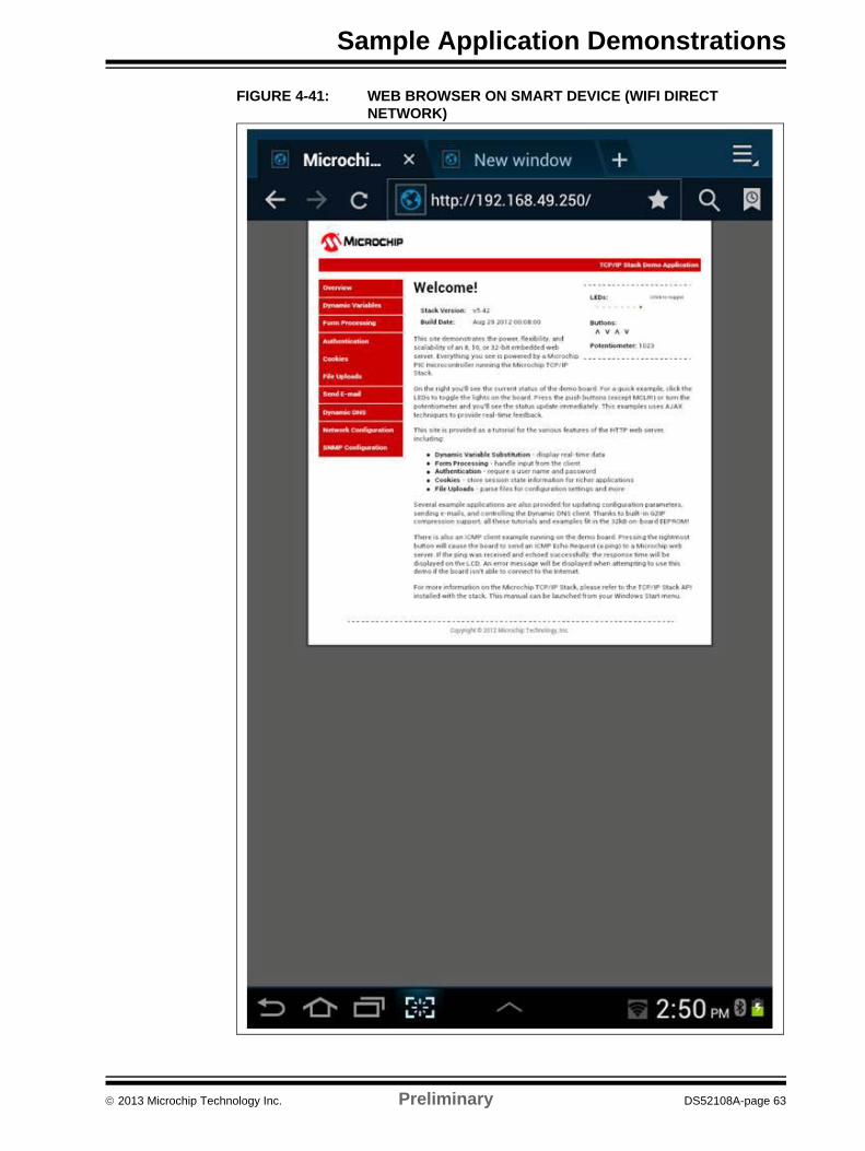
9. After connection to this WiFi Direct network is established, users can enter the Wi-Fi Direct network IP address (for example, 192.168.49.250) on the smart device’s web browser. The demonstration is similar to the Infrastructure Network type, see Figure 4-41.
DS52108A-page 62 Preliminary 2013 Microchip Technology Inc.
Sample Application Demonstrations
FIGURE 4-41: WEB BROWSER ON SMART DEVICE (WIFI DIRECT NETWORK)
2013 Microchip Technology Inc. Preliminary DS52108A-page 63
Microchip MRF24W Getting Started Guide for MRF24WB0MA/B, MRF24WG0MA/B for MLA v5
4.7.4 WPS Connection Method
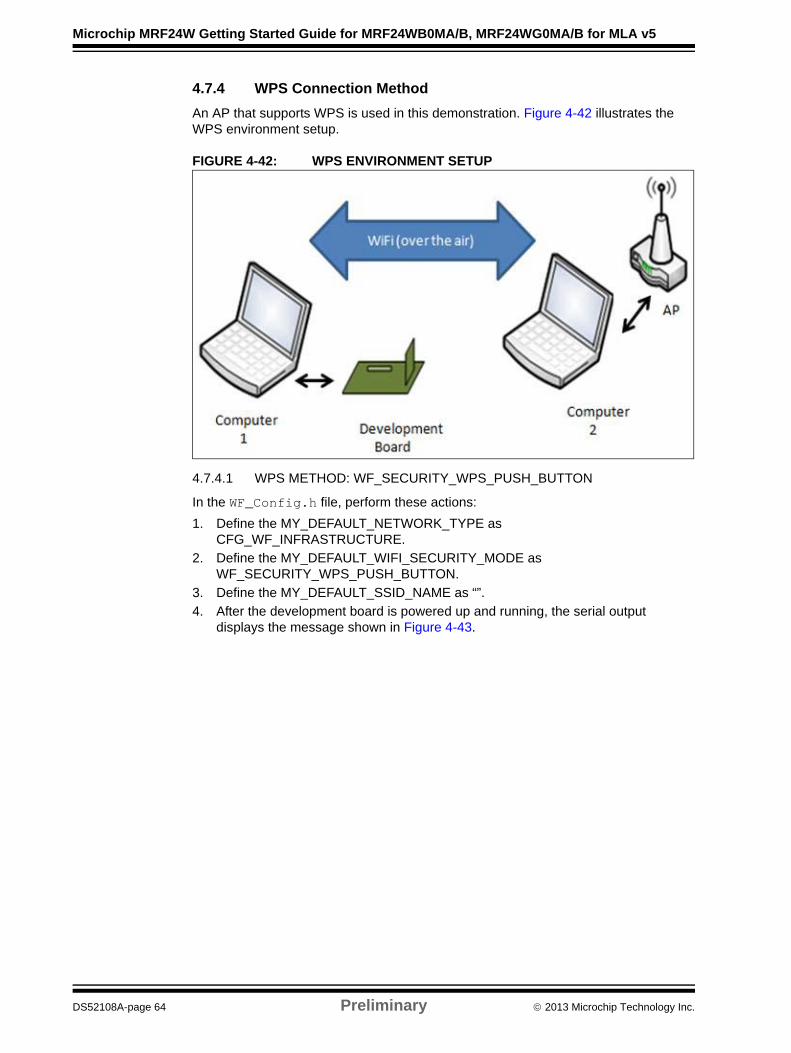
An AP that supports WPS is used in this demonstration. Figure 4-42 illustrates the WPS environment setup.
FIGURE 4-42: WPS ENVIRONMENT SETUP
4.7.4.1 WPS METHOD: WF_SECURITY_WPS_PUSH_BUTTON
In the WF_Config.h file, perform these actions:
1. Define the MY_DEFAULT_NETWORK_TYPE as CFG_WF_INFRASTRUCTURE.
2. Define the MY_DEFAULT_WIFI_SECURITY_MODE as WF_SECURITY_WPS_PUSH_BUTTON.
3. Define the MY_DEFAULT_SSID_NAME as “”.
4. After the development board is powered up and running, the serial output displays the message shown in Figure 4-43.
DS52108A-page 64 Preliminary 2013 Microchip Technology Inc.
Sample Application Demonstrations
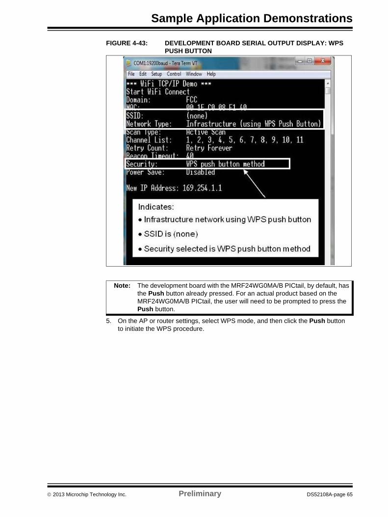
FIGURE 4-43: DEVELOPMENT BOARD SERIAL OUTPUT DISPLAY: WPS PUSH BUTTON
5. On the AP or router settings, select WPS mode, and then click the Push button to initiate the WPS procedure.
Note: The development board with the MRF24WG0MA/B PICtail, by default, has the Push button already pressed. For an actual product based on the MRF24WG0MA/B PICtail, the user will need to be prompted to press the Push button.
2013 Microchip Technology Inc. Preliminary DS52108A-page 65

Microchip MRF24W Getting Started Guide for MRF24WB0MA/B, MRF24WG0MA/B for MLA v5
FIGURE 4-44: ACCESS POINT/ROUTER WPS PUSH BUTTON METHOD
6. The AP will search and connect to the client devices, see Figure 4-45 and Figure 4-46.
FIGURE 4-45: ACCESS POINT/ROUTER IN SEARCH MODE
DS52108A-page 66 Preliminary 2013 Microchip Technology Inc.

Sample Application Demonstrations
FIGURE 4-46: ACCESS POINT/ROUTER FOUND AND CONNECTING TO DEVELOPMENT BOARD
7. After the development board has established the connection, the AP prompts the message as shown in Figure 4-47.
FIGURE 4-47: ACCESS POINT/ROUTER WPS PUSH BUTTON METHOD: SUCCESSFUL CONNECTION
8. Click OK.
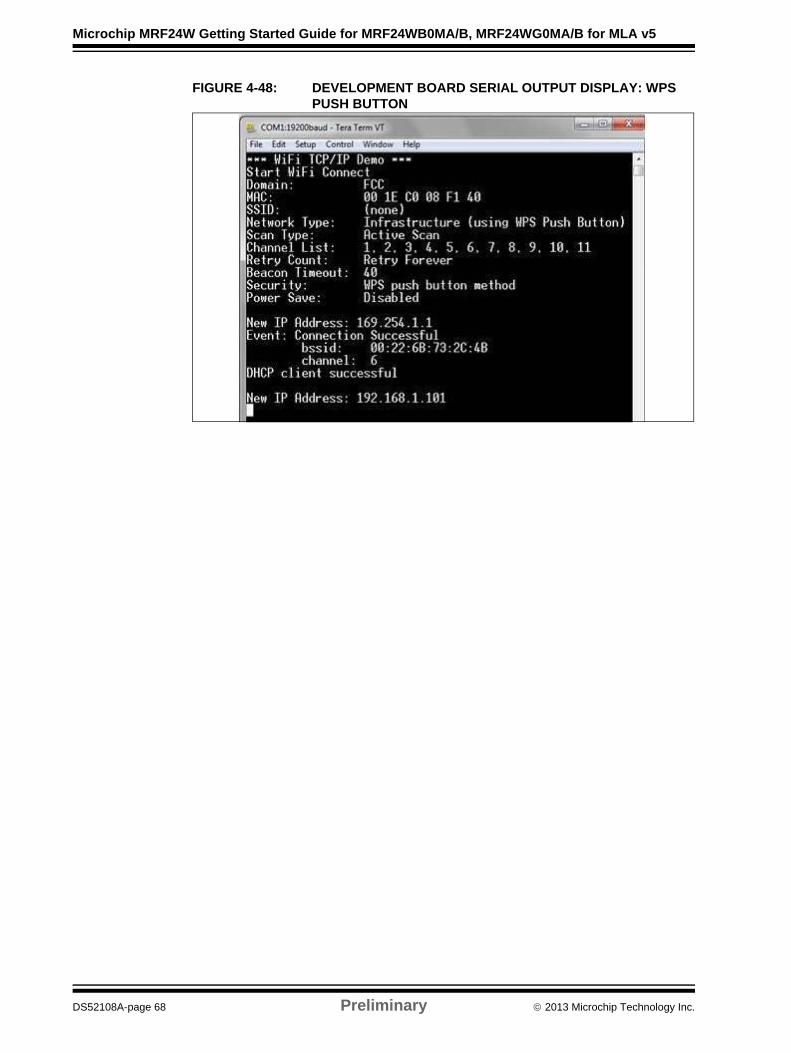
9. The serial output will display the connection details as shown in Figure 4-48.
2013 Microchip Technology Inc. Preliminary DS52108A-page 67
Microchip MRF24W Getting Started Guide for MRF24WB0MA/B, MRF24WG0MA/B for MLA v5
FIGURE 4-48: DEVELOPMENT BOARD SERIAL OUTPUT DISPLAY: WPS PUSH BUTTON
DS52108A-page 68 Preliminary 2013 Microchip Technology Inc.
Sample Application Demonstrations
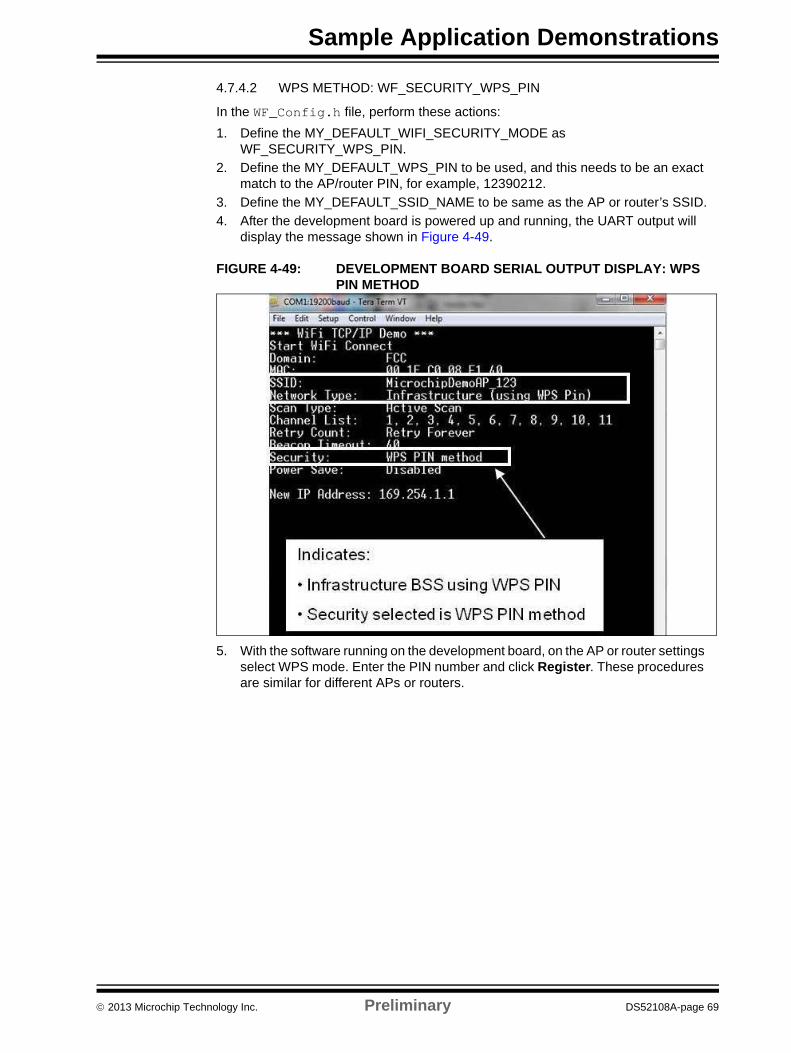
4.7.4.2 WPS METHOD: WF_SECURITY_WPS_PIN
In the WF_Config.h file, perform these actions:
1. Define the MY_DEFAULT_WIFI_SECURITY_MODE as WF_SECURITY_WPS_PIN.
2. Define the MY_DEFAULT_WPS_PIN to be used, and this needs to be an exact match to the AP/router PIN, for example, 12390212.
3. Define the MY_DEFAULT_SSID_NAME to be same as the AP or router’s SSID.
4. After the development board is powered up and running, the UART output will display the message shown in Figure 4-49.
FIGURE 4-49: DEVELOPMENT BOARD SERIAL OUTPUT DISPLAY: WPS PIN METHOD
5. With the software running on the development board, on the AP or router settings select WPS mode. Enter the PIN number and click Register. These procedures are similar for different APs or routers.
2013 Microchip Technology Inc. Preliminary DS52108A-page 69
Microchip MRF24W Getting Started Guide for MRF24WB0MA/B, MRF24WG0MA/B for MLA v5
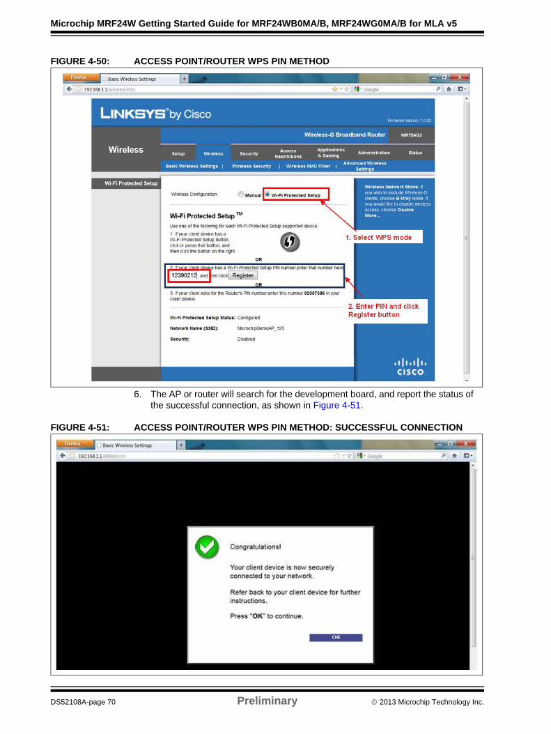
FIGURE 4-50: ACCESS POINT/ROUTER WPS PIN METHOD
6. The AP or router will search for the development board, and report the status of the successful connection, as shown in Figure 4-51.
FIGURE 4-51: ACCESS POINT/ROUTER WPS PIN METHOD: SUCCESSFUL CONNECTION
DS52108A-page 70 Preliminary 2013 Microchip Technology Inc.

Sample Application Demonstrations
7. After AP or router accepts the connection request, the development board will display the status as connection successful, see Figure 4-52.
FIGURE 4-52: DEVELOPMENT BOARD SERIAL OUTPUT DISPLAY: WPS PIN METHOD
2013 Microchip Technology Inc. Preliminary DS52108A-page 71
Microchip MRF24W Getting Started Guide for MRF24WB0MA/B, MRF24WG0MA/B for MLA v5
4.8 RUNNING THE TCPIP – WIFI CONSOLE
This demonstration supports the following network types:
• CFG_WF_INFRASTRUCTURE
• CFG_WF_ADHOC
• CFG_WF_P2P.
This section only elaborates the CFG_WF_INFRASTRUCTURE network type. Refer to 4.1.1 “TCPIP – Demo App”, for more information on the CFG_WF_ADHOC and CFG_WF_P2P network types.
Iperf is a commonly used network test tool that allows user to test throughput for network performance measurements. Iperf operates with a server and a client. The client will send data to the server at a specified rate and the bandwidth will be calculated from the server side (even though both the client and server will produce throughput numbers, the numbers that are in the server window are the most accurate). Iperf requires the serial UART port to be connected to a computer (issuing commands through the HyperTerminal session). To run the Iperf demonstration, compile the correct project. Refer to 4.3 “Opening Existing Projects”, but instead use the projects that are located in C:\Microchip Solutions\ TCPIP\ WiFi Console\.
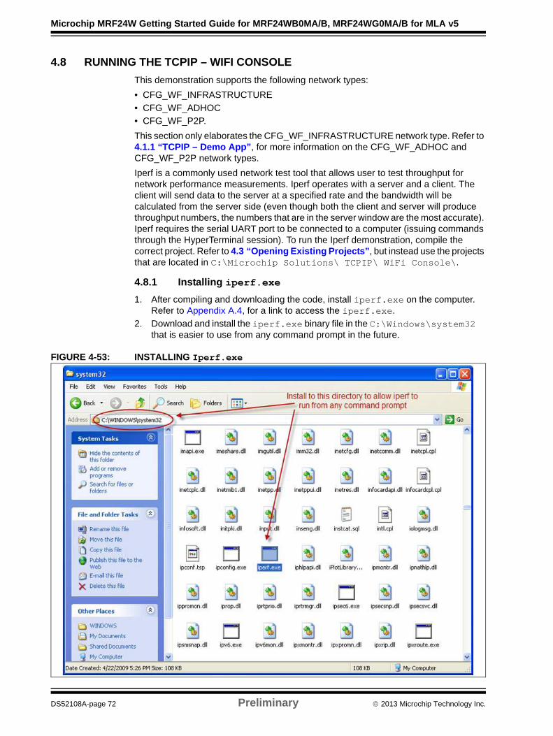
4.8.1 Installing iperf.exe
1. After compiling and downloading the code, install iperf.exe on the computer. Refer to Appendix A.4, for a link to access the iperf.exe.
2. Download and install the iperf.exe binary file in the C:\Windows\system32 that is easier to use from any command prompt in the future.
FIGURE 4-53: INSTALLING Iperf.exe
DS52108A-page 72 Preliminary 2013 Microchip Technology Inc.
Sample Application Demonstrations
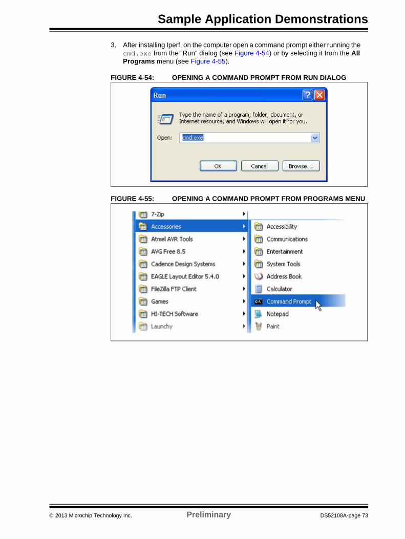
3. After installing Iperf, on the computer open a command prompt either running the cmd.exe from the “Run” dialog (see Figure 4-54) or by selecting it from the All Programs menu (see Figure 4-55).
FIGURE 4-54: OPENING A COMMAND PROMPT FROM RUN DIALOG
FIGURE 4-55: OPENING A COMMAND PROMPT FROM PROGRAMS MENU
2013 Microchip Technology Inc. Preliminary DS52108A-page 73
Microchip MRF24W Getting Started Guide for MRF24WB0MA/B, MRF24WG0MA/B for MLA v5
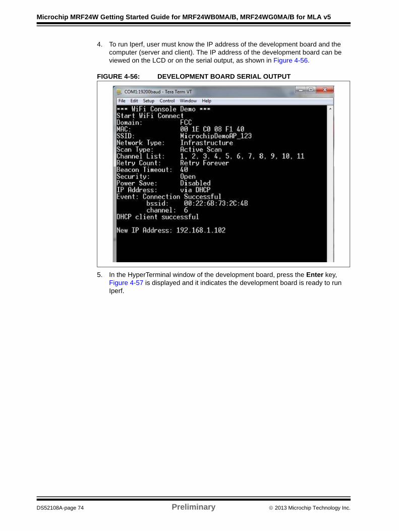
4. To run Iperf, user must know the IP address of the development board and the computer (server and client). The IP address of the development board can be viewed on the LCD or on the serial output, as shown in Figure 4-56.
FIGURE 4-56: DEVELOPMENT BOARD SERIAL OUTPUT
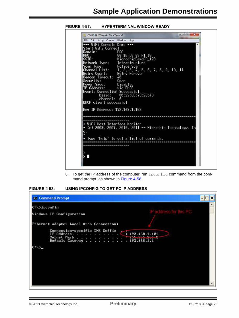
5. In the HyperTerminal window of the development board, press the Enter key, Figure 4-57 is displayed and it indicates the development board is ready to run Iperf.
DS52108A-page 74 Preliminary 2013 Microchip Technology Inc.
Sample Application Demonstrations
FIGURE 4-57: HYPERTERMINAL WINDOW READY
6. To get the IP address of the computer, run ipconfig command from the com-mand prompt, as shown in Figure 4-58.
FIGURE 4-58: USING IPCONFIG TO GET PC IP ADDRESS
2013 Microchip Technology Inc. Preliminary DS52108A-page 75
Microchip MRF24W Getting Started Guide for MRF24WB0MA/B, MRF24WG0MA/B for MLA v5
4.8.2 ipconfig Command Details
A typical server and client command, and what the options meaning is provided below:
• iperf –s –u –i <seconds>Where,
-s indicates the server
-u sends UDP datagrams
–i <seconds> indicates frequency of the status update
• iperf –c <ip_addr> -b <bw> -i <seconds> -t <seconds>Where,
-c indicates the client
<ip_addr> is the IP address of the server to communicate to
-b <bw> specifies the amount of data to try and pass through as bandwidth
-i <seconds> indicates how often the screen updates the status
-t <seconds> indicates how long to run the test for
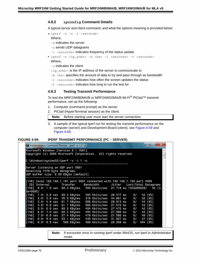
4.8.3 Testing Transmit Performance
To test the MRF24WB0MA/B or MRF24WG0MA/B Wi-Fi® PICtail™ transmit performance, set up the following:
1. Computer (command prompt) as the server.
2. PICtail (HyperTerminal session) as the client.
3. A sample of the typical Iperf run for testing the transmit performance on the computer (server) and Development Board (client), see Figure 4-59 and Figure 4-60.
FIGURE 4-59: IPERF TRANSMIT PERFORMANCE (PC – SERVER)
Note: Before starting user must start the server connection.
Note: If encounter error in running Iperf under WinOS, run Iperf in Administrator mode.
DS52108A-page 76 Preliminary 2013 Microchip Technology Inc.
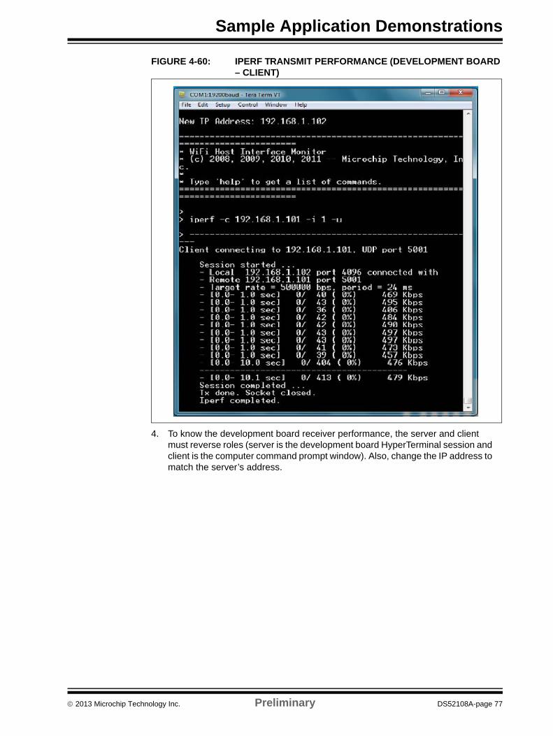
Sample Application Demonstrations
FIGURE 4-60: IPERF TRANSMIT PERFORMANCE (DEVELOPMENT BOARD – CLIENT)
4. To know the development board receiver performance, the server and client must reverse roles (server is the development board HyperTerminal session and client is the computer command prompt window). Also, change the IP address to match the server’s address.
2013 Microchip Technology Inc. Preliminary DS52108A-page 77
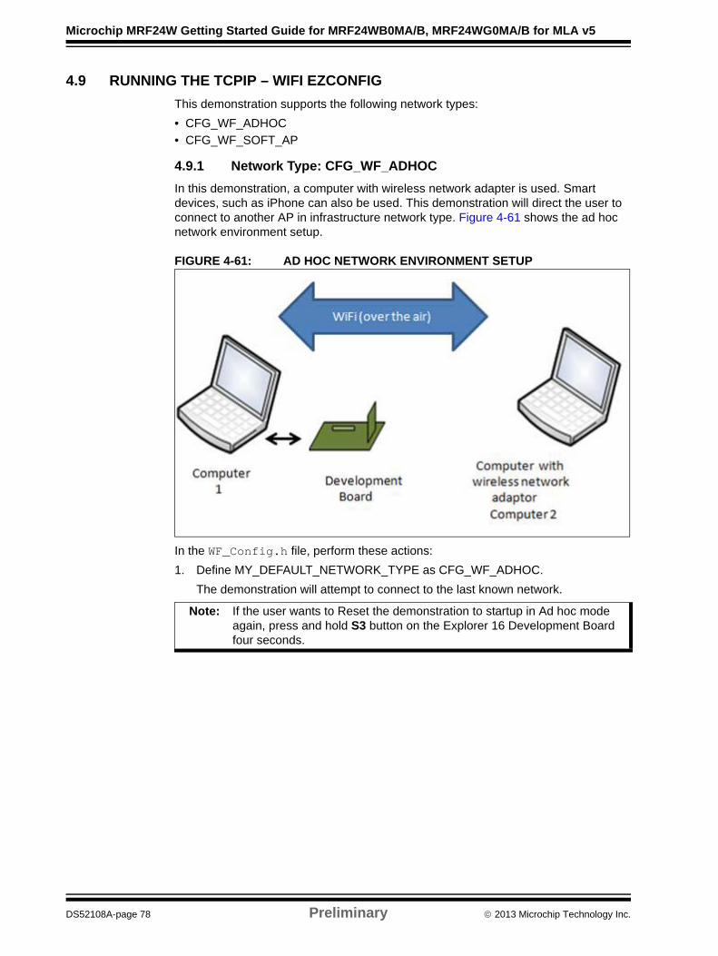
Microchip MRF24W Getting Started Guide for MRF24WB0MA/B, MRF24WG0MA/B for MLA v5
4.9 RUNNING THE TCPIP – WIFI EZCONFIG
This demonstration supports the following network types:
• CFG_WF_ADHOC
• CFG_WF_SOFT_AP
4.9.1 Network Type: CFG_WF_ADHOC
In this demonstration, a computer with wireless network adapter is used. Smart devices, such as iPhone can also be used. This demonstration will direct the user to connect to another AP in infrastructure network type. Figure 4-61 shows the ad hoc network environment setup.
FIGURE 4-61: AD HOC NETWORK ENVIRONMENT SETUP
In the WF_Config.h file, perform these actions:
1. Define MY_DEFAULT_NETWORK_TYPE as CFG_WF_ADHOC.
The demonstration will attempt to connect to the last known network.
Note: If the user wants to Reset the demonstration to startup in Ad hoc mode again, press and hold S3 button on the Explorer 16 Development Board four seconds.
DS52108A-page 78 Preliminary 2013 Microchip Technology Inc.

Sample Application Demonstrations
FIGURE 4-62: PRESS S3 BUTTON ON EXPLORER 16 DEVELOPMENT BOARD TO RESET DEMO)
2. The serial output is changed to indicate Reset is effective, see Figure 4-63.
FIGURE 4-63: DEVELOPMENT BOARD SERIAL OUTPUT DISPLAY: RESET MESSAGE
3. After the development board has established connection with computer 2, the LCD panel will display the IP address of the computer that is being used. Alternately, the serial output should display similar information, see Figure 4-64.
2013 Microchip Technology Inc. Preliminary DS52108A-page 79
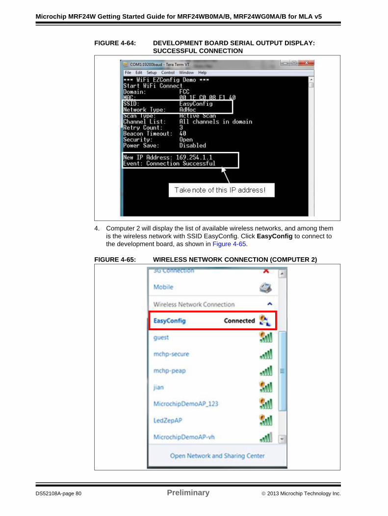
Microchip MRF24W Getting Started Guide for MRF24WB0MA/B, MRF24WG0MA/B for MLA v5
FIGURE 4-64: DEVELOPMENT BOARD SERIAL OUTPUT DISPLAY: SUCCESSFUL CONNECTION
4. Computer 2 will display the list of available wireless networks, and among them is the wireless network with SSID EasyConfig. Click EasyConfig to connect to the development board, as shown in Figure 4-65.
FIGURE 4-65: WIRELESS NETWORK CONNECTION (COMPUTER 2)
DS52108A-page 80 Preliminary 2013 Microchip Technology Inc.
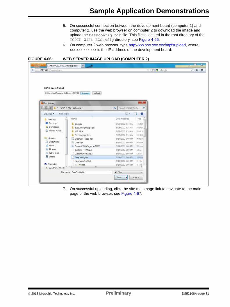
Sample Application Demonstrations
5. On successful connection between the development board (computer 1) and computer 2, use the web browser on computer 2 to download the image and upload the Easyconfig.bin file. This file is located in the root directory of the TCPIP-WiFi EZConfig directory, see Figure 4-66.
6. On computer 2 web browser, type http://xxx.xxx.xxx.xxx/mpfsupload, where xxx.xxx.xxx.xxx is the IP address of the development board.
FIGURE 4-66: WEB SERVER IMAGE UPLOAD (COMPUTER 2)
7. On successful uploading, click the site main page link to navigate to the main page of the web browser, see Figure 4-67.
2013 Microchip Technology Inc. Preliminary DS52108A-page 81
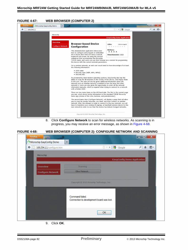
Microchip MRF24W Getting Started Guide for MRF24WB0MA/B, MRF24WG0MA/B for MLA v5
FIGURE 4-67: WEB BROWSER (COMPUTER 2)
8. Click Configure Network to scan for wireless networks. As scanning is in progress, you may receive an error message, as shown in Figure 4-68.
FIGURE 4-68: WEB BROWSER (COMPUTER 2): CONFIGURE NETWORK AND SCANNING
9. Click OK.
DS52108A-page 82 Preliminary 2013 Microchip Technology Inc.
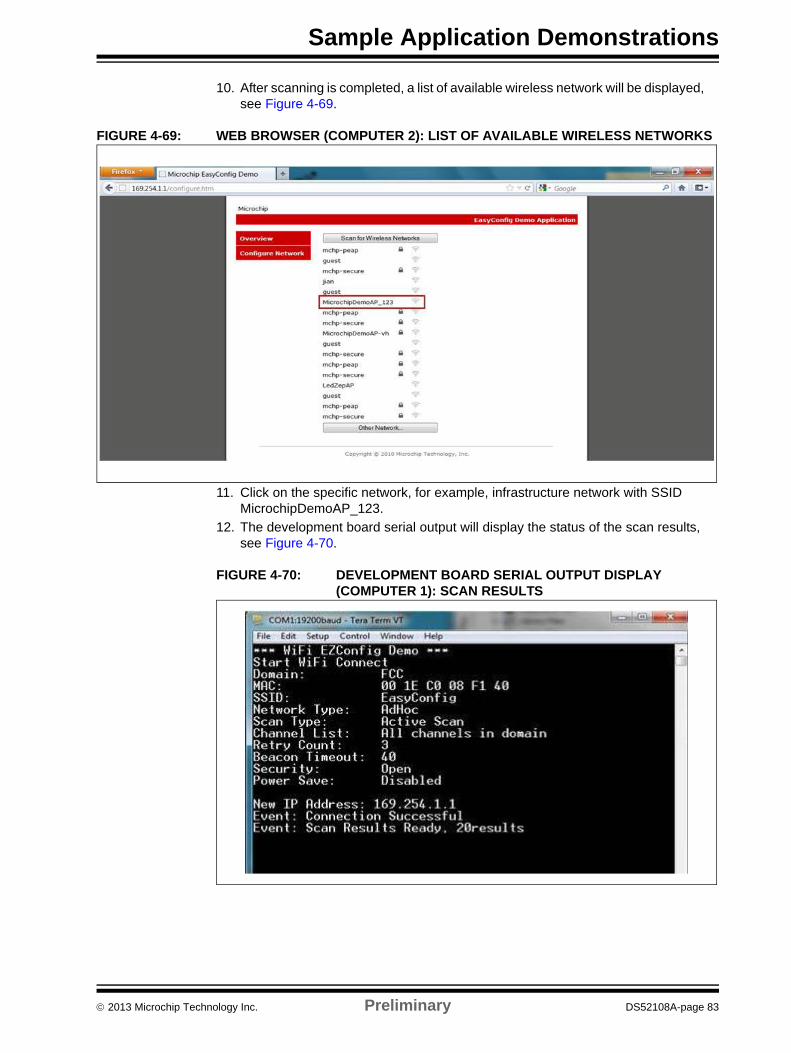
Sample Application Demonstrations
10. After scanning is completed, a list of available wireless network will be displayed, see Figure 4-69.
FIGURE 4-69: WEB BROWSER (COMPUTER 2): LIST OF AVAILABLE WIRELESS NETWORKS
11. Click on the specific network, for example, infrastructure network with SSID MicrochipDemoAP_123.
12. The development board serial output will display the status of the scan results, see Figure 4-70.
FIGURE 4-70: DEVELOPMENT BOARD SERIAL OUTPUT DISPLAY (COMPUTER 1): SCAN RESULTS
2013 Microchip Technology Inc. Preliminary DS52108A-page 83
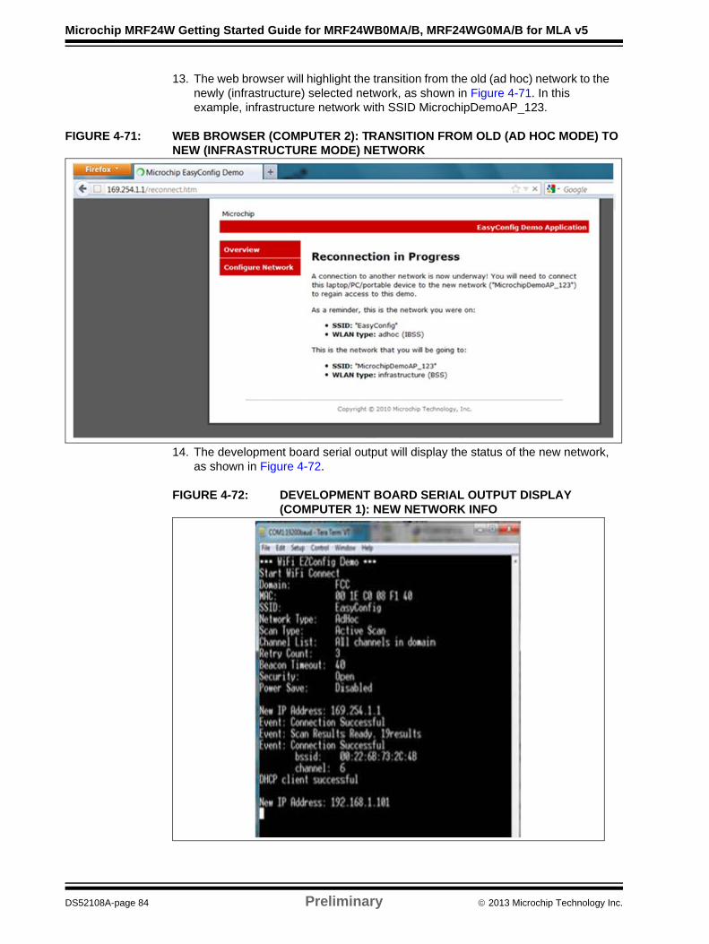
Microchip MRF24W Getting Started Guide for MRF24WB0MA/B, MRF24WG0MA/B for MLA v5
13. The web browser will highlight the transition from the old (ad hoc) network to the newly (infrastructure) selected network, as shown in Figure 4-71. In this example, infrastructure network with SSID MicrochipDemoAP_123.
FIGURE 4-71: WEB BROWSER (COMPUTER 2): TRANSITION FROM OLD (AD HOC MODE) TO NEW (INFRASTRUCTURE MODE) NETWORK
14. The development board serial output will display the status of the new network, as shown in Figure 4-72.
FIGURE 4-72: DEVELOPMENT BOARD SERIAL OUTPUT DISPLAY (COMPUTER 1): NEW NETWORK INFO
DS52108A-page 84 Preliminary 2013 Microchip Technology Inc.
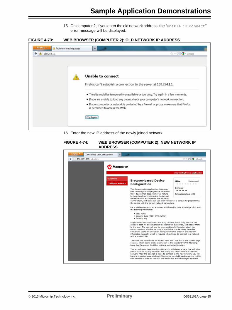
Sample Application Demonstrations
15. On computer 2, if you enter the old network address, the “Unable to connect” error message will be displayed.
FIGURE 4-73: WEB BROWSER (COMPUTER 2): OLD NETWORK IP ADDRESS
16. Enter the new IP address of the newly joined network.
FIGURE 4-74: WEB BROWSER (COMPUTER 2): NEW NETWORK IP ADDRESS
2013 Microchip Technology Inc. Preliminary DS52108A-page 85
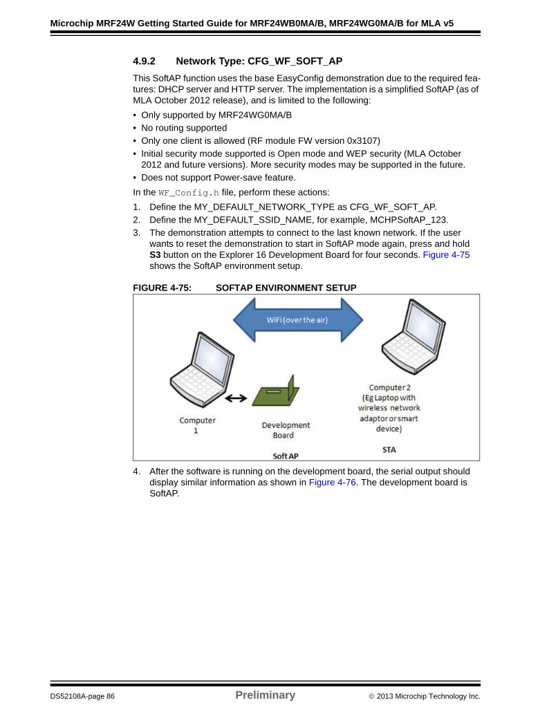
Microchip MRF24W Getting Started Guide for MRF24WB0MA/B, MRF24WG0MA/B for MLA v5
4.9.2 Network Type: CFG_WF_SOFT_AP
This SoftAP function uses the base EasyConfig demonstration due to the required fea-tures: DHCP server and HTTP server. The implementation is a simplified SoftAP (as of MLA October 2012 release), and is limited to the following:
• Only supported by MRF24WG0MA/B
• No routing supported
• Only one client is allowed (RF module FW version 0x3107)
• Initial security mode supported is Open mode and WEP security (MLA October 2012 and future versions). More security modes may be supported in the future.
• Does not support Power-save feature.
In the WF_Config.h file, perform these actions:
1. Define the MY_DEFAULT_NETWORK_TYPE as CFG_WF_SOFT_AP.
2. Define the MY_DEFAULT_SSID_NAME, for example, MCHPSoftAP_123.
3. The demonstration attempts to connect to the last known network. If the user wants to reset the demonstration to start in SoftAP mode again, press and hold S3 button on the Explorer 16 Development Board for four seconds. Figure 4-75 shows the SoftAP environment setup.
FIGURE 4-75: SOFTAP ENVIRONMENT SETUP
4. After the software is running on the development board, the serial output should display similar information as shown in Figure 4-76. The development board is SoftAP.
DS52108A-page 86 Preliminary 2013 Microchip Technology Inc.
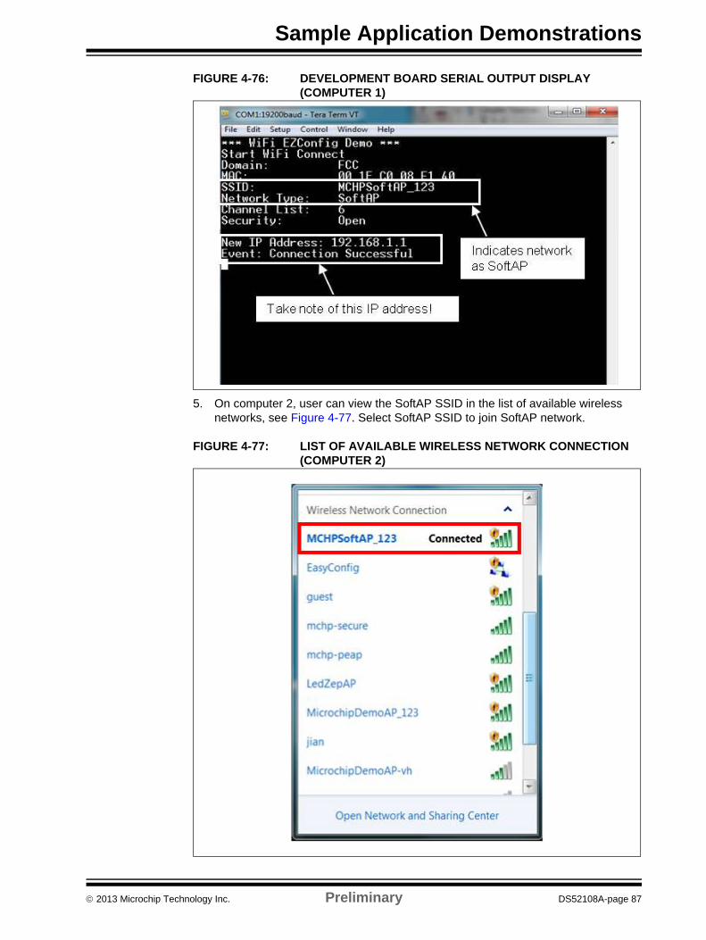
Sample Application Demonstrations
FIGURE 4-76: DEVELOPMENT BOARD SERIAL OUTPUT DISPLAY (COMPUTER 1)
5. On computer 2, user can view the SoftAP SSID in the list of available wireless networks, see Figure 4-77. Select SoftAP SSID to join SoftAP network.
FIGURE 4-77: LIST OF AVAILABLE WIRELESS NETWORK CONNECTION (COMPUTER 2)
2013 Microchip Technology Inc. Preliminary DS52108A-page 87
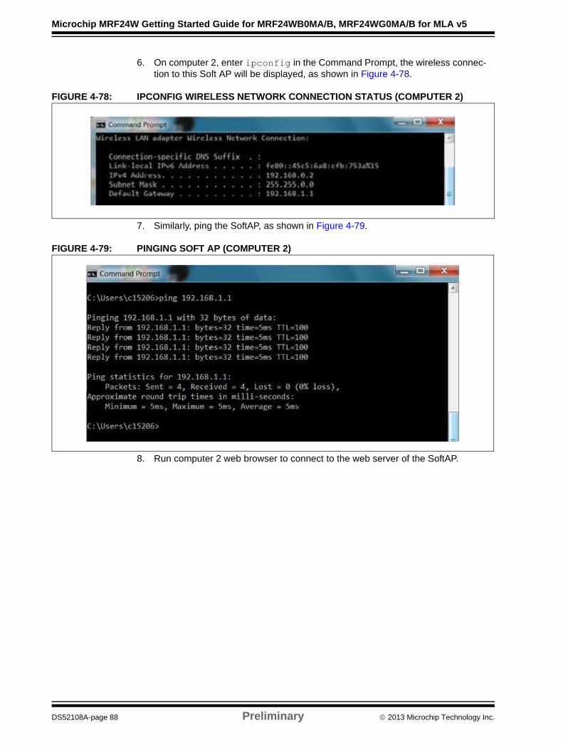
Microchip MRF24W Getting Started Guide for MRF24WB0MA/B, MRF24WG0MA/B for MLA v5
6. On computer 2, enter ipconfig in the Command Prompt, the wireless connec-tion to this Soft AP will be displayed, as shown in Figure 4-78.
FIGURE 4-78: IPCONFIG WIRELESS NETWORK CONNECTION STATUS (COMPUTER 2)
7. Similarly, ping the SoftAP, as shown in Figure 4-79.
FIGURE 4-79: PINGING SOFT AP (COMPUTER 2)
8. Run computer 2 web browser to connect to the web server of the SoftAP.
DS52108A-page 88 Preliminary 2013 Microchip Technology Inc.

Sample Application Demonstrations
FIGURE 4-80: WEB BROWSER (COMPUTER 2)
2013 Microchip Technology Inc. Preliminary DS52108A-page 89
Microchip MRF24W Getting Started Guide for MRF24WB0MA/B, MRF24WG0MA/B for MLA v5
NOTES:
DS52108A-page 90 Preliminary 2013 Microchip Technology Inc.
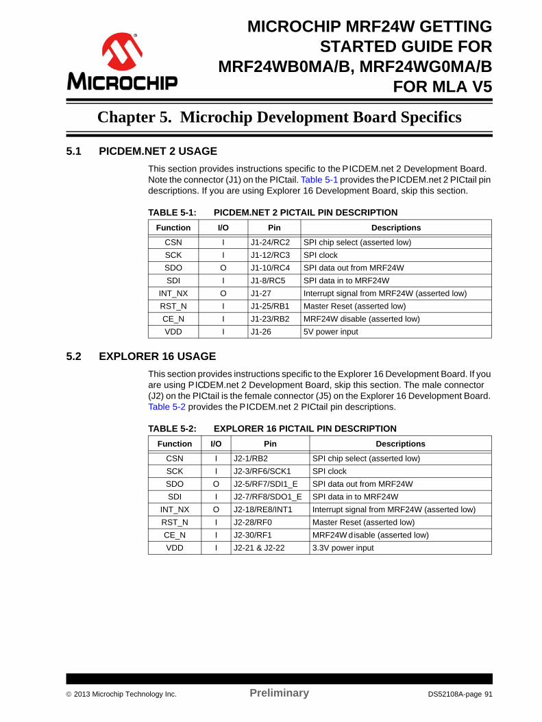
MICROCHIP MRF24W GETTINGSTARTED GUIDE FOR
MRF24WB0MA/B, MRF24WG0MA/B
FOR MLA V5Chapter 5. Microchip Development Board Specifics
5.1 PICDEM.NET 2 USAGE
This section provides instructions specific to the PICDEM.net 2 Development Board. Note the connector (J1) on the PICtail. Table 5-1 provides the PICDEM.net 2 PICtail pin descriptions. If you are using Explorer 16 Development Board, skip this section.
TABLE 5-1: PICDEM.NET 2 PICTAIL PIN DESCRIPTION
5.2 EXPLORER 16 USAGE
This section provides instructions specific to the Explorer 16 Development Board. If you are using PICDEM.net 2 Development Board, skip this section. The male connector (J2) on the PICtail is the female connector (J5) on the Explorer 16 Development Board. Table 5-2 provides the PICDEM.net 2 PICtail pin descriptions.
TABLE 5-2: EXPLORER 16 PICTAIL PIN DESCRIPTION
Function I/O Pin Descriptions
CSN I J1-24/RC2 SPI chip select (asserted low)
SCK I J1-12/RC3 SPI clock
SDO O J1-10/RC4 SPI data out from MRF24W
SDI I J1-8/RC5 SPI data in to MRF24W
INT_NX O J1-27 Interrupt signal from MRF24W (asserted low)
RST_N I J1-25/RB1 Master Reset (asserted low)
CE_N I J1-23/RB2 MRF24W disable (asserted low)
VDD I J1-26 5V power input
Function I/O Pin Descriptions
CSN I J2-1/RB2 SPI chip select (asserted low)
SCK I J2-3/RF6/SCK1 SPI clock
SDO O J2-5/RF7/SDI1_E SPI data out from MRF24W
SDI I J2-7/RF8/SDO1_E SPI data in to MRF24W
INT_NX O J2-18/RE8/INT1 Interrupt signal from MRF24W (asserted low)
RST_N I J2-28/RF0 Master Reset (asserted low)
CE_N I J2-30/RF1 MRF24W disable (asserted low)
VDD I J2-21 & J2-22 3.3V power input
2013 Microchip Technology Inc. Preliminary DS52108A-page 91
Microchip MRF24W Getting Started Guide for MRF24WB0MA/B, MRF24WG0MA/B for MLA v5
5.3 ERASING EEPROM
When debugging, if code settings (especially related to SSID name, MAC address and so on) are not effected, then erase the EEPROM. The values in the EEPROM takes precedence over values that are defined in the source code (that is, TCPIPConfig.h).
To erase the EEPROM, perform these actions:
1. Ensure that the development board is programmed and not in Debug mode.
2. Disconnect the MPLAB® ICD 3 or MPLAB REAL ICE™ from the Development Board.
3. Press and hold BUTTON0 (RD13/S4 on Explorer 16 Development Board and RB3/S5 on the PICDEM.net™ 2 Development Board).
4. Press the MCLR button.
5. Continue holding BUTTON0 until several LEDs flash indicates the EEPROM is cleared. This takes about four seconds. Alternately, if UART is connected to the development board, the following output is displayed:
BUTTON0 held for more than 4 seconds. Default settings restored
6. Release the BUTTON0.
7. Press the MCLR button again to Reset the software.
DS52108A-page 92 Preliminary 2013 Microchip Technology Inc.

MICROCHIP MRF24W GETTINGSTARTED GUIDE FOR
MRF24WB0MA/B, MRF24WG0MA/B
FOR MLA V5Appendix A. Appendix
A.1 MICROCHIP HARDWARE
Microchip hardware, including the MRF24WB0MA/B or MRF24WG0MA/B Wi-Fi® PIC-tail™ can be purchased from Microchip Direct (http://www.microchipdirect.com) or from any of the Microchip distributors.
Microchip development tool MPLAB ICD 3 In-Circuit Debugger (ICD) (http://www.microchip.com/stellent/idcplg?IdcService=SS_GET_PAGE&nodeId=1406&dDocName=en537580)
A.2 MICROCHIP SOFTWARE
• TCP/IP stack source code (http://www.microchip.com/stellent/idcplg?IdcService=SS_GET_PAGE&nodeId=2680&dDocName=en537041)
• MPLAB X IDE (http://www.microchip.com/pagehandler/en-us/family/mplabx/)
• MPLAB XC Compiler (http://www.microchip.com/pagehandler/en_us/devtools/mplabxc/)
A.3 MRF24WB0MA/B OR MRF24WG0MA/B WI-FI® RESOURCES
The MRF24WB0MA/B or MRF24WG0MA/B Wi-Fi® support web site (http://www.microchip.com/pagehandler/en-us/technology/wifi), contains the latest information, application notes, errata, module data sheets, and other useful information.
A.4 TOOLS
• Iperf (http://www.softpedia.com/progDownload/Iperf-Download-78352.html)
• Wireshark PSK calculator (http://www.wireshark.org/tools/wpa-psk.html)
• WEP Key calculator (http://wepkey.com)
• WEP Key ASCII calculator (http://www.andrewscompanies.com/tools/wep.asp)
2013 Microchip Technology Inc. Preliminary DS52108A-page 93

Microchip MRF24W Getting Started Guide for MRF24WB0MA/B, MRF24WG0MA/B for MLA v5
NOTES:
DS52108A-page 94 Preliminary 2013 Microchip Technology Inc.

2013 Microchip Technology Inc. Preliminary DS52108A-page 95
DS52108A-page 96 2013 Microchip Technology Inc.
AMERICASCorporate Office2355 West Chandler Blvd.Chandler, AZ 85224-6199Tel: 480-792-7200 Fax: 480-792-7277Technical Support: http://www.microchip.com/supportWeb Address: www.microchip.com
AtlantaDuluth, GA Tel: 678-957-9614 Fax: 678-957-1455
BostonWestborough, MA Tel: 774-760-0087 Fax: 774-760-0088
ChicagoItasca, IL Tel: 630-285-0071 Fax: 630-285-0075
ClevelandIndependence, OH Tel: 216-447-0464 Fax: 216-447-0643
DallasAddison, TX Tel: 972-818-7423 Fax: 972-818-2924
DetroitFarmington Hills, MI Tel: 248-538-2250Fax: 248-538-2260
IndianapolisNoblesville, IN Tel: 317-773-8323Fax: 317-773-5453
Los AngelesMission Viejo, CA Tel: 949-462-9523 Fax: 949-462-9608
Santa ClaraSanta Clara, CA Tel: 408-961-6444Fax: 408-961-6445
TorontoMississauga, Ontario, CanadaTel: 905-673-0699 Fax: 905-673-6509
ASIA/PACIFICAsia Pacific OfficeSuites 3707-14, 37th FloorTower 6, The GatewayHarbour City, KowloonHong KongTel: 852-2401-1200Fax: 852-2401-3431
Australia - SydneyTel: 61-2-9868-6733Fax: 61-2-9868-6755
China - BeijingTel: 86-10-8569-7000 Fax: 86-10-8528-2104
China - ChengduTel: 86-28-8665-5511Fax: 86-28-8665-7889
China - ChongqingTel: 86-23-8980-9588Fax: 86-23-8980-9500
China - HangzhouTel: 86-571-2819-3187 Fax: 86-571-2819-3189
China - Hong Kong SARTel: 852-2943-5100 Fax: 852-2401-3431
China - NanjingTel: 86-25-8473-2460Fax: 86-25-8473-2470
China - QingdaoTel: 86-532-8502-7355Fax: 86-532-8502-7205
China - ShanghaiTel: 86-21-5407-5533 Fax: 86-21-5407-5066
China - ShenyangTel: 86-24-2334-2829Fax: 86-24-2334-2393
China - ShenzhenTel: 86-755-8864-2200 Fax: 86-755-8203-1760
China - WuhanTel: 86-27-5980-5300Fax: 86-27-5980-5118
China - XianTel: 86-29-8833-7252Fax: 86-29-8833-7256
China - XiamenTel: 86-592-2388138 Fax: 86-592-2388130
China - ZhuhaiTel: 86-756-3210040 Fax: 86-756-3210049
ASIA/PACIFICIndia - BangaloreTel: 91-80-3090-4444 Fax: 91-80-3090-4123
India - New DelhiTel: 91-11-4160-8631Fax: 91-11-4160-8632
India - PuneTel: 91-20-2566-1512Fax: 91-20-2566-1513
Japan - OsakaTel: 81-6-6152-7160 Fax: 81-6-6152-9310
Japan - TokyoTel: 81-3-6880- 3770 Fax: 81-3-6880-3771
Korea - DaeguTel: 82-53-744-4301Fax: 82-53-744-4302
Korea - SeoulTel: 82-2-554-7200Fax: 82-2-558-5932 or 82-2-558-5934
Malaysia - Kuala LumpurTel: 60-3-6201-9857Fax: 60-3-6201-9859
Malaysia - PenangTel: 60-4-227-8870Fax: 60-4-227-4068
Philippines - ManilaTel: 63-2-634-9065Fax: 63-2-634-9069
SingaporeTel: 65-6334-8870Fax: 65-6334-8850
Taiwan - Hsin ChuTel: 886-3-5778-366Fax: 886-3-5770-955
Taiwan - KaohsiungTel: 886-7-213-7828Fax: 886-7-330-9305
Taiwan - TaipeiTel: 886-2-2508-8600 Fax: 886-2-2508-0102
Thailand - BangkokTel: 66-2-694-1351Fax: 66-2-694-1350
EUROPEAustria - WelsTel: 43-7242-2244-39Fax: 43-7242-2244-393Denmark - CopenhagenTel: 45-4450-2828 Fax: 45-4485-2829
France - ParisTel: 33-1-69-53-63-20 Fax: 33-1-69-30-90-79
Germany - MunichTel: 49-89-627-144-0 Fax: 49-89-627-144-44
Italy - Milan Tel: 39-0331-742611 Fax: 39-0331-466781
Netherlands - DrunenTel: 31-416-690399 Fax: 31-416-690340
Spain - MadridTel: 34-91-708-08-90Fax: 34-91-708-08-91
UK - WokinghamTel: 44-118-921-5869Fax: 44-118-921-5820
Worldwide Sales and Service
11/29/12


![OdakyuAndroid t Google play] Wi-Fi Android ios t App Store] Wi-Fi [App Store] [iPhone Profile) Wi-Fi # —E Odakyu Odakyu Free Wi-Fi Android [Google play] WI-Fi Android [App Wi-Fi](https://static.documents.pub/doc/80x56/5fcc31f69b77e950d81a9828/android-t-google-play-wi-fi-android-ios-t-app-store-wi-fi-app-store-iphone.jpg)