Vol. 56 JOURNAL OF THE OPTICAL SOCIETY OF AMERICA VOLUME 56, NUMBER 3 Wide-Angle Michelson Interferometer for Measuring Doppler Line Widths* R. L. HILLIARDt BND G. G. SHEPHERD Institute of Upper A tmospheric Physics, University of Saskatchiewan, Saskatoon, Canada (Received 30 July 1965) The field-compensation principle, which has been applied to interferometric spectroscopy independently by P. Connes and by L. Mertz, allows the useful solid angle accepted by an interferometer to be increased by an amount that can be very large. This paper is concerned with a particular application of this principle using the Michelson interferometer. Although the technique is difficult to utilize where a wide range of path differences is required, the interferometer takes an extremely simple form when constructed for a narrow range of path difference about a fixed central path difference. While such an instrument has a limited use in spectroscopy, there is one type of measurement which it is admirably suited to perform: the determina- tion of the width of a single isolated atomic line whose analytical shape is known. A description is given of the theory and construction of a wide-angle Michelson interferometer now being used for the measurement of Doppler temperatures from the width of the 5577 . atomic oxygen line in the nightglow and aurora. This line is known to be accurately gaussian in shape, and is well-isolated from other lines, making it an ideal subject for this instrument. INDEX HEADINGS: Interferometer; Spectroscopy; Doppler effect. 1. INTRODUCTION INTERFEROMETRIC spectroscopy is becoming in- creasingly common, particularly in those labora- tories where the experiments are limited by the source brightness. This is because of the general recognition that with interferometric devices, a greater photon flux is delivered to the detector for a given source radiance and spectral resolution. Jacquinot', who first pointed this out, used the word luminosity to describe this characteristic. Since that word has another meaning, we use radiance response here instead, and mean by it the photon flux delivered to the detector divided by the source radiance. Of the various interferometers, that of Fabry and Perot has perhaps been the most widely used so far, despite the limitation of its multiple passbands. But this limitation can be overcome with multiple 6talon systems; successful tandem instruments have been constructed.2-4 The other important spectroscopic interferometer is that of Michelson; it has been success- * Presented at the Spring Meeting of the Optical Society of America in Dallas, 2 April 1965. J. Opt. Soc. Am. 55, 615A (1965). t Present Address: Steward Observatory, University of Arizona, Tucson, Arizona 85721. 1 P. Jacquinot, J. Opt. Soc. Am. 44, 761 (1954). 2 R. Chabbal, Thises, Universitd de Paris, 1958. 3J. E. Mack, D. P. McNutt, F. L. Roesler, and R. Chabbal, Appl. Opt. 2, 873 (1963). ' G. G. Shepherd, C. W. Lake, J. R. Miller, and L. L. Cogger, Appl. Opt. 4, 267 (1965). fully employed by several users. 5 - 8 Its great flexi- bility is achieved at the cost of having to compute numerical Fourier transforms. The ingenious SISAM, 9 and the multislit spectrom- eter' 0 have not yet been much used, although Tinsley" has recently described a promising form of the latter instrument. For a review of this field, readers are referred to the paper by Jacquinot,' 2 then director of the laboratory responsible for many of the recent developments in interferometric spectroscopy. At Saskatoon, spectroscopic measurements of upper atmospheric temperature have been carried out for many years, in particular, rotational temperature measure- ments from molecular bands.' 3 Most recently, two series of Doppler temperature measurements in aurora were made with a Fabry-Perot spectrometer.' 4 " 5 With the latter, Doppler temperatures having a probable error of 501K were obtained from weak S P. Fellgett, J. Phys. Radium 19, 237 (1958). 6J. Connes, J. Phys. Radium 19, 197 (1958). 7 H. A. Gebbie, J. Phys. Radium 19, 230 (1958). 8 J. Connes and H. Gush, J. Phys. Radium 20, 915 (1959). 9 P. Connes, J. Phys. Radium 19, 215 (1958). 10 A. Girard, Appl. Opt. 2, 79 (1963). 11 B. A. Tinsley, J. Opt. Soc. Am. 55, 599A (1965). 12 P. Jacquinot, Rep. Progr. Phys. 23, 267 (1960). 13 D. M. Hunten, Ann. Geophys. 17, 249 (1961). 1 ' 1 J. A. Nilson and G. G. Shepherd, Planetary Space Sci. 5, 299 (1961). 16 E. C. Turgeon and G. G. Shepherd, Planetary Space Sci. 9, 295 (1962). MARCH 1966 362
Transcript
Vol. 56
JOURNAL OF THE OPTICAL SOCIETY OF AMERICA VOLUME 56, NUMBER 3
Wide-Angle Michelson Interferometer for Measuring Doppler Line Widths*R. L. HILLIARDt BND G. G. SHEPHERD
Institute of Upper A tmospheric Physics, University of Saskatchiewan, Saskatoon, Canada
(Received 30 July 1965)
The field-compensation principle, which has been applied to interferometric spectroscopy independentlyby P. Connes and by L. Mertz, allows the useful solid angle accepted by an interferometer to be increasedby an amount that can be very large. This paper is concerned with a particular application of this principleusing the Michelson interferometer. Although the technique is difficult to utilize where a wide range of pathdifferences is required, the interferometer takes an extremely simple form when constructed for a narrowrange of path difference about a fixed central path difference. While such an instrument has a limited usein spectroscopy, there is one type of measurement which it is admirably suited to perform: the determina-tion of the width of a single isolated atomic line whose analytical shape is known. A description is given ofthe theory and construction of a wide-angle Michelson interferometer now being used for the measurementof Doppler temperatures from the width of the 5577 . atomic oxygen line in the nightglow and aurora.This line is known to be accurately gaussian in shape, and is well-isolated from other lines, making it an idealsubject for this instrument.INDEX HEADINGS: Interferometer; Spectroscopy; Doppler effect.
1. INTRODUCTION
INTERFEROMETRIC spectroscopy is becoming in-creasingly common, particularly in those labora-
tories where the experiments are limited by the sourcebrightness. This is because of the general recognitionthat with interferometric devices, a greater photon fluxis delivered to the detector for a given source radianceand spectral resolution. Jacquinot', who first pointedthis out, used the word luminosity to describe thischaracteristic. Since that word has another meaning,we use radiance response here instead, and mean by itthe photon flux delivered to the detector divided by thesource radiance.
Of the various interferometers, that of Fabry andPerot has perhaps been the most widely used so far,despite the limitation of its multiple passbands. Butthis limitation can be overcome with multiple 6talonsystems; successful tandem instruments have beenconstructed.2-4 The other important spectroscopicinterferometer is that of Michelson; it has been success-
* Presented at the Spring Meeting of the Optical Society ofAmerica in Dallas, 2 April 1965. J. Opt. Soc. Am. 55, 615A (1965).
t Present Address: Steward Observatory, University of Arizona,Tucson, Arizona 85721.
1 P. Jacquinot, J. Opt. Soc. Am. 44, 761 (1954).2 R. Chabbal, Thises, Universitd de Paris, 1958.3J. E. Mack, D. P. McNutt, F. L. Roesler, and R. Chabbal,
Appl. Opt. 2, 873 (1963).' G. G. Shepherd, C. W. Lake, J. R. Miller, and L. L. Cogger,
Appl. Opt. 4, 267 (1965).
fully employed by several users.5- 8 Its great flexi-bility is achieved at the cost of having to computenumerical Fourier transforms.
The ingenious SISAM,9 and the multislit spectrom-eter'0 have not yet been much used, although Tinsley"has recently described a promising form of the latterinstrument. For a review of this field, readers arereferred to the paper by Jacquinot,'2 then director ofthe laboratory responsible for many of the recentdevelopments in interferometric spectroscopy.
At Saskatoon, spectroscopic measurements of upperatmospheric temperature have been carried out for manyyears, in particular, rotational temperature measure-ments from molecular bands.'3 Most recently, two seriesof Doppler temperature measurements in aurora weremade with a Fabry-Perot spectrometer.'4"5
With the latter, Doppler temperatures having aprobable error of 501K were obtained from weak
S P. Fellgett, J. Phys. Radium 19, 237 (1958).6 J. Connes, J. Phys. Radium 19, 197 (1958).7 H. A. Gebbie, J. Phys. Radium 19, 230 (1958).8 J. Connes and H. Gush, J. Phys. Radium 20, 915 (1959).9 P. Connes, J. Phys. Radium 19, 215 (1958).10 A. Girard, Appl. Opt. 2, 79 (1963).11 B. A. Tinsley, J. Opt. Soc. Am. 55, 599A (1965).12 P. Jacquinot, Rep. Progr. Phys. 23, 267 (1960).13 D. M. Hunten, Ann. Geophys. 17, 249 (1961).1'1J. A. Nilson and G. G. Shepherd, Planetary Space Sci. 5,
299 (1961).16 E. C. Turgeon and G. G. Shepherd, Planetary Space Sci. 9,
295 (1962).
MARCH 1966
362
WIDE-ANGLE MICHELSON INTERFEROMETER
auroras using scanning times of about 15 secs. A double-6talon instrument has subsequently been used fordayglow observations.' Although the Fabry-Perotspectrometer has been very useful, a substantiallygreater radiance response is desirable to permit obser-vations of time-dependent auroral phenomena, as wellas fainter emissions such as nightglow.
The ordinary Michelson interferometer yields thesame radiance response as the Fabry-Perot spectrom-eter; it therefore offers no advantages for this particularapplication. However, the useful field of the Michelsoninterferometer may be widened (or compensated), asshown originally by Hansen"7 -"9 and described laterby Connes20 and Mertz,2" by making the path differenceof the interferometer a slowly varying function ofincidence angle. The gain of radiance response overthat of the uncompensated instrument increases withthe path difference used; for line-width studies it willbe demonstrated that gains of about one thousand arepossible in principle. Field compensation of the Fabry-Perot spectrometer can be accomplished with sphericalplates,22 but the resulting gain is significant only atresolving powers much greater than those requiredfor these measurements.
We therefore directed our attention to the Michelsoninterferometer. A very simple arrangement pro-vides correct field compensation for a given pathdifference. This makes the device highly suitable forDoppler line-width measurements because the widthof an isolated line of known shape may be determinedby observing the fringe modulation over a single orderof interference at a particular path difference. More-over, this may be done without numerical Fouriertransformation.
The following sections of this paper contain: a dis-cussion of the method for determining a line width fromthe modulation obtained over a very narrow range ofpath difference centered at some particular path dif-ference, a simple explanation of the field-compensationprinciple, a more detailed analysis, and finally a descrip-tion of the instrument and some sample results. Becausethe term "compensation" can be applied to the inter-ferometer in both the spatial and the spectral sense,this term is avoided in this paper; the term Wide AngleMichelson Interferometer (WAMI) is used instead,and the symbol MI used for the ordinary instrument.
16 A. R. Bens, L. L. Cogger, and G. G. Shepherd, PlanetarySpace Sci. 13, 551 (1965).
17 G. Hansen, Optik 12, 5 (1955).18 G. Hansen and W. Kinder, Optik 15, 560 (1958).19 The authors are indebted to Dr. W. H. Steel for drawing
these references to their attention.20 P. Connes, Rev. Opt. 35, 37 (1956).21 L. Mertz, preprints of papers presented at the Fifth Meeting
and Conference of the I. C. O., Stockholm, Aug. 1959. Ed.: E.Ingelstam.
99 P. Connes, J. Phys. Radium 19, 262 (1958).
2. MEASUREMENT OF DOPPLER LINE WIDTHWITH A MICHELSON INTERFEROMETER
As is well-known, the variable part of the inter-ferogram produced as the interferometer scans is theFourier transform of the source spectrum.'2 We arehere concerned with a source spectrum that is an iso-lated gaussian line centered at wavenumber cro. Thedifferential source radiance as a function of wavenum-ber o- is given by
Bo-Bo exp[- (a-_-o)2 4 ln2/w2], (1)
where w is the half-intensity width of the line, whichin the case of purely Doppler broadening can be relatedto the source temperature T by,
(2)
where T is in 'K and M is the mass of the atomic speciesin amu.
The Fourier transform of a gaussian of width wcentered at a-o in "a space" is, in "path-difference space"a gaussian of half-intensity width (4 ln2)-/(7r2w2),centered at a path difference A= 0, and multiplied bycos27ro-OA. This result was worked out explicitly byMichelson.2" As pointed out by Jacquinot,'2 the gaussianenvelope is very conveniently identified with Michel-son's concept of fringe visibility. Accordingly, bymaking use of Eq. (2), we can express the visibility as
V= exp[-QTA 2 ],where
(3)
(4)
For the 5577-A line of atomic oxygen, Eq. (4) becomes
Q= 3.66X 10⁻⁵ K1 cm-2. (5)
It is thus seen that a measurement of V leads directlyto the determination of temperature T, assuming, ofcourse, that the interferometer and source are perfect.Techniques for removing the necessity for these assump-tions are discussed later.
3. THE FIELD-COMPENSATION PRINCIPLE
The field-compensation principle can be explainedsimply by referring to Fig. 1, in which a conventionalMI is shown, and Fig. 2 in which the WAMI is shown.In Fig. 1 the movable mirror M 2 is shown in two posi-tions. Position 1, where M2 is coplanar with the imageMl' of Ml, corresponds to zero path difference, andposition 2, where M2 is parallel to but not coplanar withM1 ', corresponds to some finite path difference. Thepath of an off-axis ray through the system is shown.For position 1, the divided rays, after recombination,emerge collinearly from the instrument. For position 2,the two ray components have a relative displacement.
23 A. A. Michelson, Studies in Optics, (University of ChicagoPress, Chicago, 1927).
363March 1966
w= (7.16X10⁻¹)o-o(T1M),-
Q = ((7.16)2X 10-14/4 ln2) (70o-o�/M).
364 R. L. HILLIARD AND G. G. SHEPHERD Vol. 56
P . 2 --- --- collinearly from the instrument (to the approximationMl Position that the position of Ml' is independent of incidence
/ \ angle). But the path difference is not zero, since thetravel time for light in the path containing the slab is
/ Beamsplitter longer than in the path in air.This effect can be readily verified experimentally by
i \observing the fringes produced by a narrow-line sourceMl with the above arrangement. As the path difference
for which the above condition occurs is approached, thefringes expand and the visibility becomes large just ashappens near zero path difference in the MI. In otherwords, some of the zero path characteristics of the MIappear at some particular nonzero path difference in
Light\ In the WAMI; that path difference shall be referred to asthe quasi-zero path difference, abbreviated QZP.
For normally incident light Fig. 2 shows that the
M2
FIG. 1. The conventional Michelson interferometer. Position 1of Ml' is for zero path difference, and the emergent rays arecollinear. Position 2 corresponds to a nonzero path difference, M -and the emergent rays have a relative displacement. i a\
It follows that for position 1 the path difference is zero /regardless of the angle of incidence (because the ray / bpaths form identical triangles on both sides of thebeamsplitter), whereas in position 2 the path differencen cbecomes a function of the angle. In short, it can besaid that an MI with zero path difference is a perfectlyfield-compensated instrument. A
In Fig. 2 the mirror M2 has been replaced by a back-aluminized plane-parallel glass slab. This slab is soplaced that the virtual image of its back face coincides detail. The path in glass is indicated by the solid line, and thewith MI'. The result is that the ray components emerge superimposed path in air is shown as the dotted line.
AM2 path difference is equal to 2nt- 2t', where t is the thick-
/ ness of the slab, I' is the apparent distance to the virtualI - - \ Ml - .~image of the back surface, and n is the refractive index
t ,/1 of the slab. It will be seen later that it is difficult tol1 tdefine a physically meaningful QZP condition precisely;
ml /for convenience and simplicity we shall say that theQZP condition occurs when t' is equal to t/n. The path
h In difference for normal incidence at the QZP conditionis thus given by
Ao (QZP)= 2 (nt-I/n). (6)
4. CALCULATION OF THE VARIATION OFBeamsplitter PATH DIFFERENCE WITH ANGLE
Because the position of M1' varies with incidentangle, perfect field compensation is not possible. A moreprecise analysis is required to determine the limits ofthis compensation. The path difference for an off-axisray may be calculated by reference to Fig. 3. This
FIG. 2. Wide-angle Michelson interferometer. The front-surfaced figure is an elaboration of Fig. 2 but shows the pathsmirror M2 has been replaced by a back-surfaced slab of refractive only near the mirrors M 1 and M 2. The two paths areindex it. The dotted line indicates the apparent path of the ray shown superipsdwthheotdlnerrsnigin the slab as reflected from the vertical image of M2 . Although w t d l gthere is a nonzero Dath difference, the emergent rays are collinear. the path which is in air. The case considered is one in
-~~~~~~_ - __ I - - f
WIDE-ANGLE MICHELSON INTERFEROMETER
which the image M1' does not coincide with the virtualimage of M2 but is located close to it. Using the nota-tion of the Figure and recalling that the ray shown assolid is in glass of refractive index n and that the pathshown dotted is in air, we find the path difference:
A = 2na-2b-s. (7)
The path segments a, b, and s are given by,
a= t/cos9p., b= t'/cossp, (8)and
s= 2 sinQ (t tan9p -t' tany p). (9)
As shown in Fig. 3, t and An. are, respectively, the slabthickness and ray angle with the normal for the path inglass, while I' and so are the analogous quantities forthe path in air. Substituting Eq. (8) and Eq. (9) intoEq. (7) and using Snell's law, we obtain,
A=2(tn cosy,-t' costs). (10)
When s9= 0 and I' is set equal to I/n, Eq. (10) reduces toEq. (6).
The significance of Eq. (10) is not obvious at firstsight. It is instructive to calculate the change in pathdifference with angle for the situation where t'=t/n;that is, to subtract Eq. (6) from Eq. (10). If we dothis, using approximations adequate for the Fabry-Perot or Michelson interferometers (sinO=6, and coso= 1-02/2), we obtain A-Ao=O. Thus, to this degreeof approximation, the compensation is perfect and thepath difference is completely independent of the in-cidence angle.
This idea can be expressed formally by writingA-A 0 in a power series in so as follows:
A- = A so= +Bso2 f Cs3+D<'+Esp+ *- * *(11)
This equation applies to all spectrometers or inter-ferometers; for example, a grating spectrometer withnormally incident light has A-A 0 = 21 sin9Ž:2t9. Thusfor a grating spectrometer (since tO<1) the dominantterm in Eq. (11) is A 9V and the additional terms areneeded only for higher-order approximations (B, D etc.are equal to zero but that is not important here). Forthe Fabry-Perot and Michelson interferometers wehave A-Ao=-2t(1-cos9), which when expandedgives A= 0 with B o2 the dominant term. This can-cellation of the A y term gives the MI its advantageover the grating spectrometer.2 Expressed in this waythe advantage of the WAMI over the MI arises fromthe cancellation of the Bo2 term, and as shown below,the C9
3 term as well.To investigate in more detail the variation of path
difference with angle, higher powers of s must beused. In addition, the restriction that I' be equal toI/n need not be imposed; small deviations from the
24 Of course, for a grating spectrometer, the angle so determinesonly the slit width; the slit length must also be considered incomparing the two instruments.
QZP condition are expressed as the small quantity e,where
1t = t/n+ e. (12)
Using Snell's law and expanding the cosine to thefourth order, we obtain
Cos '.= (1/n)[ni2- y2+ 9413]1. (13)
If we expand Eq. (13) in a binomial expansion, expandcosy to fourth order, substitute in Eq. (10), and useEq. (6), the result is
(A- AO)WAMI = e92 + (t/4n 2 ) (n-i/n) 94. (14)
By making use of Eq. (6), we can write this as
(A- AO)wAMI= e92+Ao04 /8n2 .
The analogous equation for the MI is
(A0 A)MI= Aoyp/2-Ao9 4/24.
(15)
(16)
Comparison of Eqs. (15) and (16) shows how closely e,the distance from the QZP condition, is analogous toAo/2 for the MI. Returning to Eq. (11), we now seethat the advantage of the WAMI is that e can be setequal to zero at any path difference, eliminating allterms up to D&04, whence Eq. (14) reduces to
(A- Ao)wAI-,rAo9p 4 /8n 2 . (17)
This approximate equation is simple and often con-venient to use for the WAMI. But it is conservative,because Eq. (15) is still the accurate equation and as isshown in the next section, the use of negative e valuespermits a partial cancellation of the terms in 92 and94, and makes it possible to use off-axis angles evengreater than indicated by Eq. (17).
5. REDUCTION IN OBSERVED FRINGEVISIBILITY RESULTING FROM
A FINITE APERTURE
It is clear that for a perfectly monochromatic sourceand a pinhole aperture, V= 1, but that as the apertureis made finite, the superposition of fringes of varyingA causes the visibility to decrease to a value that weshall call the aperture visibility parameter, denoted byVa. Unlike the case for the MI,' the treatment of thiseffect for the WAMI does not lend itself to analyticalmethods. A numerical treatment is described in whatfollows.
The case for e=0 is considered first. The aperturemay be divided into annular segments, each of whichhas a path difference that diff ers from that of itsimmediate neighbors by the same amount dA. The con-tribution to the interferogram from a single segmentcan be represented by a vector with amplitude propor-tional to the area of the segment, and phase angle27r(A-Ao)/X corresponding to the value of (A-A 0 ) forthat segment. The situation is as pictured in the insetof Fig. 4. From the inset it can be seen that the segment
36i5March 1966
R. L. HILLIARD AND G. G. SHEPHERD
area is proportional to .opd', which from Eq. (17) isrelated to dA by
pdVo= n[1/2 (A- Ao)Ao]IdA. (18)
In writing this in terms of phase angles rather thanpath differences we replace dA by X6/27r, where a is theconstant incremental phase angle, A0 by M8o/27r, andA-A 0 by XN6/27r, where N is an integer giving thenumber of the segment (increasing outward from N= 1at the center to N= M at the edge of the aperture).Thus Eq. (18) is replaced by
pdV (n/2312V)k. (19)
Since bo and a are constant, the intensity amplitudevector is proportional to 1/Ni. The contribution tothe interferogram can be expressed in arbitrary units as
A exp (ia) = 1 + 1-1 exp (i3)
+2- exp(i26)+*** M- exp(iM6). (20)
The x and y components of the vector A exp(ia) werecalculated separately; the results of this calculationare shown in Fig. 4, where the y component of A hasbeen plotted against its x component for M increasingfrom 1 to 100 and 8= 0.1 rad. A smooth curve has beendrawn through the points. Some values of A-A 0 (in5577-A radiation wavelengths) and of 'oP('oPM is thevalue of 'P for the edge of the aperture) for the authors'instrument (A0= 5.2 cm) are indicated at intervalsalong the curve. However, this curve could be adaptedfor any other such instrument. As 'P increases themagnitude A increases and its phase a changes. Thevisibility parameter Va is given by the vector magni-tude of any point on the curve, divided by the arclength from the origin to that point. Before presentingresults of the calculation of Va, we will make the ex-tension to the general case (e50).
Y .2.01.06
2
0 4 6
X
FIG. 4. Showing the effect of a finite aperture on the WAMI.The geometry is shown in the inset. The spiral is the locus of thetip of a vector representing the intensity and phase of the fringestransmitted by the aperture. Moving up the spiral correspondsto opening up the aperture. The aperture half-angle *°m is shownin radians by the open arrows. The change in path differencefrom the center of the aperture to its edge is indicated, in wave-lengths, by the solid arrows. The spiral is drawn for a pathdifference of 5.0 cm and a wavelength of 5577 A
1.0
E .8
a-
: .6.u .4
-a .2a
.20.08 .12 .1
Aperture Half-angle AM (Radians)
FIG. 5. Showing how the aperture visibility parameter V0changes with aperture half-angle sot for various values of e=t'-t /n. e is the displacement from the normal incidence QZPcondition. The path difference is 5 cm. The curve marked MIis for a conventional Michelson interferometer.
The procedure used for e540 was similar to thatdescribed above, except that the segments used hadnot equal phase width but equal angular widths d'p,
instead. For each segment, the area was simply 'pdcpand Eq. (14) was used to calculate its phase angle.The results of this calculation are shown in Fig. 5as visibility parameter versus 'pM for various e, and inFig. 6 as visibility parameter versus e for various (pM.From Fig. 5 it is seen that for e= 0, Va is very closeto unity up to i M= 0.06 rad, after which it dropsrapidly. (The curve for a MI is shown on the samegraph.) For negative values of e, Va departs from unityfor smaller values of yM, but increases again at larger'PM. For example, for e=-40 A, Va=0.9 can be ob-tained at sojf=-0.12 rad, giving a fourfold increase inradiance response for only a moderate loss of visibility.On the other hand, Fig. 6 shows that as 'pM is increased,the range of e over which V0 remains near unity ismuch reduced, making the mirror location more critical.
6. RADIANCE RESPONSE AND RESOLVINGPOWER OF THE WAMI
Resolving power of a spectral device indicates aninstrument's ability to isolate a spectral feature fromits companions. In this context the concept is relativelyunambiguous. But in certain specialized studies oneis more concerned with the ability of an instrument toreproduce accurately a particular characteristic of aspectral-distribution function; for example, the widthof a single gaussian line. Though a criterion might beinvented to describe this ability, in principle this char-acteristic can be extracted from a smeared record withperfect accuracy once the instrumental characteristicsare known perfectly. For a noiseless record, this wouldyield infinite resolution in this spectral characteristic.In practice, noise is always present and the effectiveresolving power becomes a function of the signal-to-noise ratio, and therefore cannot be assigned a fixedvalue.
366 Vol. 56
WIDE-ANGLE MICHELSON INTERFEROMETER
41
-100 -60 -20 20 60 100e t'-t/n (Microns)
FIG. 6. The same data as in Fig. 5, plotted to showthe variation of VY with e for various ior.
If this is true for an instrument whose output is aspectrum, it is much more true for the WAMI as usedhere, for which the theoretical output is a functiononly of the path difference and the width of the gaussianline source. In the presence of noise the accuracy ofthe WAMI is optimized by choosing the path differencewhich gives the greatest sensitivity of visibility tosource temperature; that is, one which yields themaximum value for dV/dT. Using Eq. (2) and Eq. (3)to calculate (d/dA) (dV/dT), we find that for a givenline width w, the path difference Aw which gives dV/dTits maximum value occurs when
wA w = 2 (ln2)i/7rA0.5. (21)
This relation can be used to define a resolving powerfor the WAMI by saying that if the WAMI is set to apath difference Aw, it has a resolving power wAmwAi= o/w, where w is the line width given by Eq. (21).With this definition, w is not to be thought of as thenarrowest width the instrument can measure, but theoptimum one.
Combining Eq. (21) with this definition we get
CIWAMI = awlrAw/2 (1n2)4Ž2o-Aw. (22)
Using the definition of resolving power for the scanningMI, where now A31 is the maximum path difference,we obtain a remarkably similar equation,
61 ,M1 = 2 uA . (23)
In other words, when Aw is set equal to Am, the re-solving power of the WAMI as defined is equal to theresolving power of the MI.
The photon flux transmitted by the interferometeris given by
F=8SQTB, (24)
where S is the area of the limiting element, 1 is thesolid angle accepted by S, r is the transmittance of theinstrument, and B is the radiance of the extendedsource in photons cm-2 sec-' sr-'. The radiance re-sponse (sometimes called light-gathering power andsometimes called throughput) is proportional to Slh.
* .02 radian
(yip)wAMI/(m)xI = 2n (R) 1. (26)
The gain of the WAMI over the MI increases as thesquare root of the resolving power, and it is now clearwhy for the application discussed in this paper theWAMI shows up so favorably.
Since the assumptions made in arriving at the aboveresult may be criticized as being somewhat arbitrary,it may be worthwhile to make a more direct comparisonfor one particular case. This can be done by using theresults of Fig. 5 to compare 'pm
2 for the WAMI andMI when both are set to the same path difference of5 cm and both are used in the same way (measurementof visibility at a single path difference). If we make thecomparison for V,,= 0.9 for both instruments the resultis (vm2)wAMI/(vM2)MI= 1.2X 10³, which is very closeto the result obtained by using Eqs. (22) and (26).
7. REDUCTION IN FRINGE VISIBILITYRESULTING FROM INSTRUMENTAL
IMPERFECTIONS
In a real interferometer, the surfaces are neitherperfectly flat nor perfectly smooth, nor are they alwaysin optimum adjustment. Furthermore, the reflectancesof the beamsplitter and front- and back-surfacedmirrors are such that the two beams cannot be per-fectly balanced. All of these effects combine to makethe visibility less than unity for perfectly monochro-
The quantity S12 is called 6tendue in French, and hasbeen translated by some as light grasp, by others asflux acceptance. (This confusion in terminology hasbeen pointed out elsewhere.4) The quantity 12, thesolid angle of acceptance, is here called the angularacceptance. Since £i7ryii, it is clear from Fig. 5 thatthe WAMI is an instrument of great angular accept-ance. Even though it is used here as a high-resolutiondevice, the useful angle accepted by it is comparableto that which can be accepted by a low-resolutiondevice such as an interference filter. For example,the Oi nightglow emission at 5577 A has a B ofabout 2X10⁷ photons cm-2 sec' sr-'; therefore fortypical values of S= 20 cm2, r= 0.1, and NM1= 0.05 rad,a flux of about 0.75X 10⁶ photons/sec is obtained,which is readily measured with a photomultiplier.
Since it has already been shown that the WAMIand MI have equal "resolutions" when the fixed pathdifference for the former is equal to the maximum pathdifference for the latter, the angular acceptances forthe two devices can be compared by calculating theratio of 'Pm2 for the two instruments when both pathdifferences are equal. An approximate analytical ex-pression can be obtained by using Eqs. (16) and (17)and neglecting the q9 term for the MI. The result is,
(qIPA)WAMI/(qM2 )MI = E2n2 Aio/(A-Ao)]1, (25)
which, using either Eqs. (22) or (23), and takingA-AO= 0.5, we find to be
367March 1966
R. L. HILLIARD AND G. G. SHEPHERD
matic light and M -- > 0. Let the measured visibilityunder such conditions be called the imperfection visi-bility parameter, denoted by Vi. Then for a real sourceand a real instrument, we can write, using Eq. (3),
Vobs= VaVie-QTA 2 (27)
A line source of known visibility, such as a '5 8Hglamp can be used to determine the quantity VaVi. IfVaVi were measured as soM -- 0 then V0 and Vi couldbe determined separately for any 'pm, but there isno necessity for this in the present application and itwas not done. In any event, since a rather small 'plM
of 0.05 rad was used, V. was essentially unity.
8. THE EFFECT OF DISPERSION
The MI is normally used in a dispersion-compensatedarrangement, but it is apparent that dispersion com-pensation and field compensation are mutually exclu-sive. This means that the field compensation can bemaintained over only a limited range of wavelengths.The change in path difference dA, arising from dis-persion for a wavelength change dX, is obtained bydifferentiating Eq. (10) with t' fixed and 'pm equal tozero, giving
dA/dX= 2tdn/dX. (28)
For a spectral line width of 0.02 A, t=3 cm, andborosilicate crown glass at 5577 A, the path-differenceshift is about 10-2 wavelengths, which is just smallenough to be ignored in the present application. Butfor much broader lines, or at wavelengths near theultraviolet cutoff of the glass, the effect would beimportant and would have to be considered.
9. DESCRIPTION OF THE CONSTRUCTEDINSTRUMENT
A WAMI was constructed by the authors for thespecific purpose of measuring Doppler line widths ofemission lines of the upper atmosphere. The opticalgeometry of the interferometer is shown in Fig. 7. Thebeamsplitter substrate and compensating medium areprovided by a pair of 900 prisms. The dimensions ofthe prisms are such that together they form a cubethat is 6 cm on each side. A layer of rhodium is de-posited on the hypotenuse of one of the prisms to formthe semireflecting beamsplitter. 2 5
The optical flatness of all the critical surfaces (indi-cated by heavy lines) was X/20. The two hypotenuseswere wrung to provide a strong bond without the useof an adhesive.
The back- surface mirror (M2) was deposited on aplane-parallel glass slab. This had a physical thicknessof 3 cm and was 6 cm square. The front face of theslab was pressed against one of the prisms, with an
25 The assembly was fabricated by Hilger and Watts, Inc.
FIG. 7. Showing the configuration of the opticsused for the constructed instrument.
intervening layer of oil having a refractive index match-ing that of the glass.
This type of optical geometry has a number of ad-vantages over the conventional arrangement, whichuses four mechanically independent optical components(the two mirrors, beamsplitter substrate, and compen-sating plate). This geometry creates virtually a two-component interferometer; the only significant insta-bility is between the front-surfaced mirror (M1 ) andthe remainder of the optics. The beamsplitter is pro-tected to such a degree that it is essentially permanent.For the WAMI, the large off-axis angles can causeconsiderable vignetting unless the beamsplitter is muchlarger than the other mirrors. In the split-cube arrange-ment the sizes of the beamsplitter, as well as the sizesof the other critical surfaces, are reduced by the orderof 30%, compared to the conventional arrangement.This results in a more compact instrument and a reduc-tion in the cost of the optics.
The angles a and a' were made very nearly equal(in our case they were the same to better than a secondof arc, although a difference somewhat larger than thiscould probably be tolerated). This was to insure thatthe fringes were not distorted when large fields wereused. Small differences could have been corrected bymalting the thin oil layer assume the proper wedgeshape; but this correction was not found necessary.
The WAMI was operated exclusively in a narrowpath-difference region near 5.2 cm. It would have beenpossible to use a mechanical motion to set the mirrorM1 position for the compensation and then use alimited scanning-range technique (e.g. refractive indexor piezoelectric) to scan over the single fringe required.However, a single mechanical bearing was used toaccomplish both purposes. With this type of scanningit proved more efficient to scan over a few hundredorders before recycling M1 . The angle of the cone(2v&aI) accepted by the WAMI was set at 0.1 rad to
368 Vol. 56
WIDE-ANGLE MICHELSON INTERFEROMETER
ensure that Va did not depart significantly from unityover this range.
In practice, particularly for faint sources such asnightglow, there is a significant amount of continuousbackground radiation which must be extracted fromthe data before the analysis is done. One way to avoidthis problem would be to measure V for two differentpath differences (one of which could conveniently bevery close to zero) and to use the ratio of these valuesto calculate T. For continuous measurement, this pro-cedure would require two independent instruments. Ifthese two instruments had the same Vi, then thistechnique would eliminate the need to determine Viand would also eliminate the continuum radiation. Sincethis would be both expensive and difficult to achieve,the much simpler auxiliary interference-filter photome-ter was used. The passband of the interference filter
1*;;A:4 ..1M.... 1 1-.tn .l hfi±l '" 1l
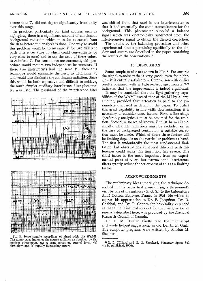
FIG. 8. Some sample recordings obtained with the WAMI.The upper trace indicates the source radiance as obtained by themonitor photometer. (a) A scan across an auroral form, (b)nightglow, and (c) rapidly fluctuating aurora.
was shifted from that used in the interferometer sothat it had essentially the same transmittance for thebackground. This photometer supplied a balancesignal which was electronically subtracted from theinterferometer signal to obtain the desired correction.
The details of the balancing procedure and otherexperimental details pertaining specifically to the air-glow and aurora are described in the paper containingthe results of the observations.26
10. DISCUSSION
Some sample results are shown in Fig. 8. For aurorasthe signal-to-noise ratio is very good; even for night-glow it is entirely satisfactory. Comparison with earlierresults obtained with a Fabry-Perot spectrometer 14 5
indicates that the improvement is indeed significant.It may be concluded that the light-gathering capa-
bilities of the WAMI exceed that of the MI by a largeamount, provided that attention is paid to the pa-rameters discussed in detail in the paper. To utilizethis great capability in line-width determinations it isnecessary to consider three factors. First, a line shape(preferably analytical) must be assumed for the emis-sion. Second, a source of known V must be available.Finally, all other radiations must be excluded, or, inthe case of background continuum, a suitable correc-tion must be made. Which of these three factors willbe limiting depends on the particular problem at hand.The first is undoubtedly the most fundamental limi-tation, but observations at several different path dif-ferences could make this limitation less severe. Thethird factor is the most important from an experi-mental point of view, but narrow-band interferencefilters greatly reduce the seriousness of this as a limitingfactor.
ACKNOWLEDGMENTS
The preliminary ideas underlying the technique de-scribed in this paper first arose during a three-monthvisit by one of the authors (G. G. S.) to the LaboratoireAim6 Cotton, Bellevue, France in 1961. He wishes toexpress his appreciation to Dr. P. Jacquinot, Dr. R.Chabbal, and Dr. P. Connes for hospitality extendedat that time. Financial support for that visit, as for allresearch described here, was provided by the NationalResearch Council of Canada.
Dr. D. M. Hunten kindly read the manuscriptand made helpful suggestions, as did Dr. H. P. Gush.The computer programs were written by Marian M.Shepherd.
26 R. L. Hilliard and G. G. Shepherd, Planetary Space Sci.(to be published, 1966).