Based on multisource wireless signal fusion technology, the autonomous positioning systems of robots have been widely employed.How to design a compact compostable antenna array for indoor robot positioning is still a problem. In this study, we proposed acompact ultrathin antenna unit that effectively reduces the mutual coupling between any adjacent units, while covering most of theexisting communication bands, including 2G/3G/4G/Wi-Fi, which will greatly reduce the size of the positioning antenna array. Theproposed antenna system has been employed for positioning purpose with high-gain, wide-frequency band and limited size. Itnecessarily improves the accuracy of positioning signal from various unknown sources and finally accomplishes its autonomouspositioning function.
1. Introduction
In the last few years, with the rapid development of theeconomy, science, and technology, intelligent robots haveemerged in every aspect of work and life. Multiple disci-plines related to the robot systems, e.g., sensors, data conver-sion, signal processing and control, artificial intelligence, andbionics, have made remarkable achievements. However,robot positioning, especially in complex environments,remains an unsolved problem [1]. In any indeterminateenvironment, a robot would scan the surroundings and cre-ates an environmental floor plan for navigation. After aninstruction is received, the robot retrieves correlation dataof the target to seek the best route and achieve an autono-mous cruising task. However, the most important prerequi-site of robot precision autonomous positioning is to establisha high-precision route database and ensure cruise accuracy[2]. Presently, normal positioning systems include laserranging sensors, RFID identification sensors, inertial naviga-tion systems (e.g., gyroscopes and accelerometers), the rastermap technology, etc. [3–6].
In this study, we propose a comprehensive positioningRF device by using various existing communication signals.
By transmitting and receiving any 2G/3G/4G/Wi-Fi signal,the novel wireless RF device would obtain real-timehigh-accuracy positioning data through a positioningalgorithm. When a robot is employed in an unknown envi-ronment, it will scan all nearby wireless signal sourcesand obtain connections with them. With the robot cruis-ing the work area and drawing a blueprint, the position-ing system also collects the various wireless signals andmakes precise area location within its coverage region.In this way, the robot needs a compact antenna systemwhich can cover more communication standards andreceive weak signals from different directions. This meansthat the positioning antenna system needs small size,high-gain multiband.
However, in present, as multi/ultrawide-band high-gainpositioning antennas are usually bulky, it is difficult to beinstalling on small robots. Therefore, a miniaturized robotpositioning antenna unit is urgently needed [7–9]. In orderto accurately detect the positioning signal source within itscoverage region, theproposedpositioningantenna systemalsorequires wide-frequency band and good directionality. In thisstudy, we propose an ultrasmall antenna unit and its array thatprovide small size, broad-frequency band, diverse layout, and
HindawiInternational Journal of Antennas and PropagationVolume 2019, Article ID 2102593, 10 pageshttps://doi.org/10.1155/2019/2102593
Omni-directional coverage to high-precision positioning sys-tems of small mobile robots.
2. Design Ideas and Methods
For an indoor robot, to collect high-precision wireless signaland obtain accurate positioning data, one small-sizedhigh-precision wireless positioning antenna system is pro-posed in this paper. The most important for a robot position-ing antenna is to reduce the size of antenna; some references[10–12] have proposed various methods to reduce the size ofthe antenna radiating unit below one-fourth the wavelength,such as a low-profile dual-polarized antenna, an EBG struc-ture antenna as radiating element, or a high-impedanceperiodic metal structure.
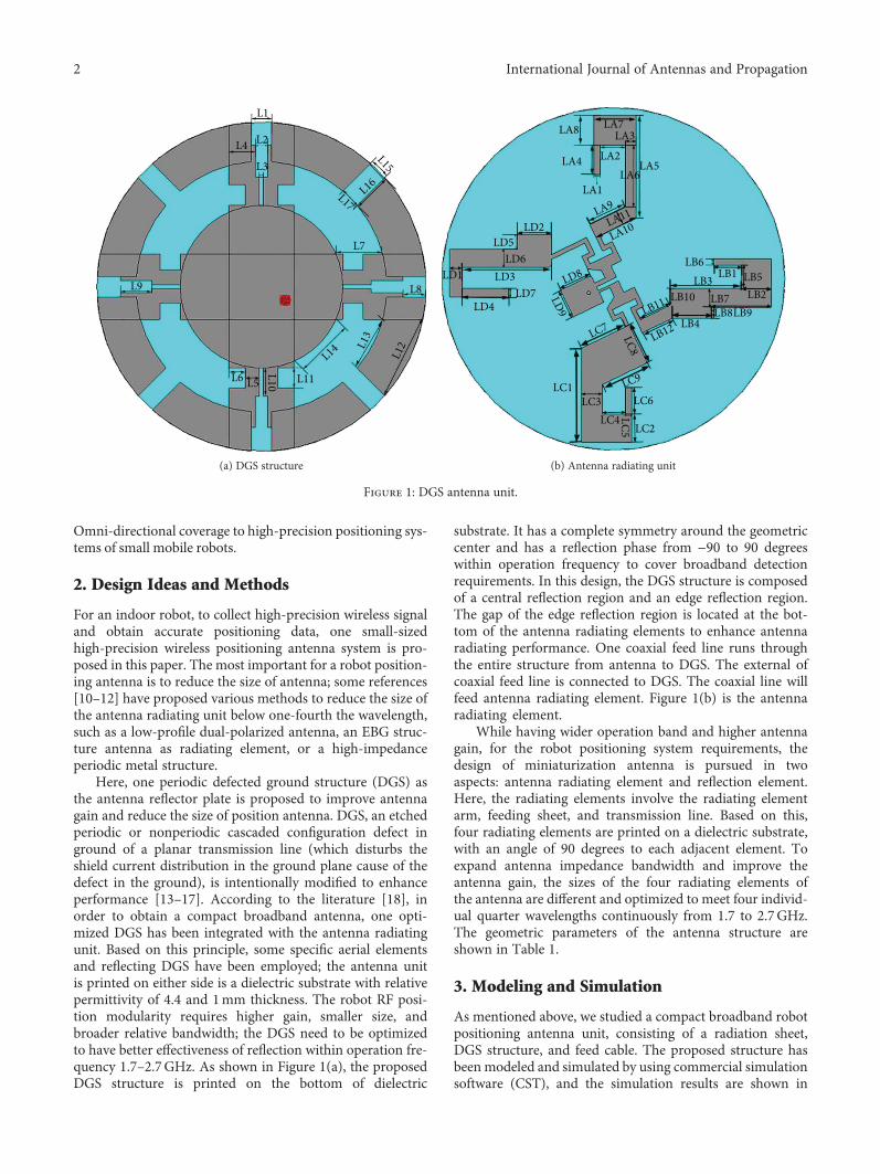
Here, one periodic defected ground structure (DGS) asthe antenna reflector plate is proposed to improve antennagain and reduce the size of position antenna. DGS, an etchedperiodic or nonperiodic cascaded configuration defect inground of a planar transmission line (which disturbs theshield current distribution in the ground plane cause of thedefect in the ground), is intentionally modified to enhanceperformance [13–17]. According to the literature [18], inorder to obtain a compact broadband antenna, one opti-mized DGS has been integrated with the antenna radiatingunit. Based on this principle, some specific aerial elementsand reflecting DGS have been employed; the antenna unitis printed on either side is a dielectric substrate with relativepermittivity of 4.4 and 1mm thickness. The robot RF posi-tion modularity requires higher gain, smaller size, andbroader relative bandwidth; the DGS need to be optimizedto have better effectiveness of reflection within operation fre-quency 1.7–2.7GHz. As shown in Figure 1(a), the proposedDGS structure is printed on the bottom of dielectric
substrate. It has a complete symmetry around the geometriccenter and has a reflection phase from −90 to 90 degreeswithin operation frequency to cover broadband detectionrequirements. In this design, the DGS structure is composedof a central reflection region and an edge reflection region.The gap of the edge reflection region is located at the bot-tom of the antenna radiating elements to enhance antennaradiating performance. One coaxial feed line runs throughthe entire structure from antenna to DGS. The external ofcoaxial feed line is connected to DGS. The coaxial line willfeed antenna radiating element. Figure 1(b) is the antennaradiating element.
While having wider operation band and higher antennagain, for the robot positioning system requirements, thedesign of miniaturization antenna is pursued in twoaspects: antenna radiating element and reflection element.Here, the radiating elements involve the radiating elementarm, feeding sheet, and transmission line. Based on this,four radiating elements are printed on a dielectric substrate,with an angle of 90 degrees to each adjacent element. Toexpand antenna impedance bandwidth and improve theantenna gain, the sizes of the four radiating elements ofthe antenna are different and optimized to meet four individ-ual quarter wavelengths continuously from 1.7 to 2.7GHz.The geometric parameters of the antenna structure areshown in Table 1.
3. Modeling and Simulation
As mentioned above, we studied a compact broadband robotpositioning antenna unit, consisting of a radiation sheet,DGS structure, and feed cable. The proposed structure hasbeen modeled and simulated by using commercial simulationsoftware (CST), and the simulation results are shown in
L1
L2L4
L3
L15
L16L17
L7
L8
L12L1
3L14
L11L5L6 L10
L9
(a) DGS structure
LA7LA8
LA4 LA5LA6
LA1
LA9LA11
LA10
LA3
LA2
LD2LD5
LD6LD3LD1
LD4LD7
LC1LC3 LC6
LC2LC4 LC5
LC9
LC8
LC7LD9
LD8LB6
LB1
LB10LB11 LB7
LB3
LB8LB9LB4
LB12
LB5LB2
(b) Antenna radiating unit
Figure 1: DGS antenna unit.
2 International Journal of Antennas and Propagation
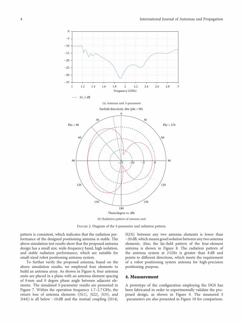
Figure 2, that is, antenna unit S-parameter in Figure 2(a)and radiation pattern of the antenna unit in Figure 2(b).The S-parameters are simulated within 1–3GHz. The sim-ulated result indicates that the return loss ( S11 ) of theantenna unit is less than −10dB within the operating fre-quency. Also, the radiation gain of the antenna unit isgreater than 2dB.
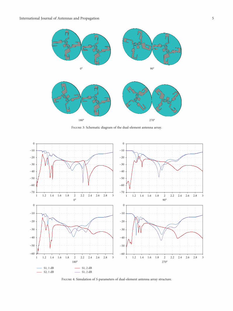
In order to verify the practicality and reduce the size ofthe proposed DGS antenna, we employ a couple of units tobuild one antenna array. Taking the extreme case as an exam-ple, the interval between two antenna units is 0 cm andcophase feeding with constant amplitude is conducted on adual-element antenna, as shown in Figure 3. To test the per-formance of the antenna unit in various circumstances, thephase angle of the dual-element antenna unit is, respectively,set to 0°, 90°, 180°, or 270°.
The simulated results of the S-parameters are shown inFigure 4. S11 and S22 are the return losses of two ports,and S21 is the isolation between the two ports. As shownin Figure 4, all simulated S11 and S22 are below −10dBwithin working frequency 1.2–2.7GHz, while the simulatedS21 is below −20 dB, indicating that the designed antennaunits have good impedance bandwidth characteristics and agood isolation between the two units because of the adoptedDGS reflection technology. Even the interval between twoantenna elements is 0 cm, this greatly improves the adaptabil-ity of the antenna unit and enables them to be intensivelyarranged without affecting antenna performance, whichgreatly reduces the geometric size of the antenna array suit-able for a robot positioning system. Through differentarrangements and increasing or decreasing the number ofantennas, the antenna system can achieve the desired perfor-mance of the antenna positioning system.
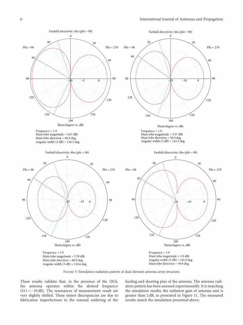
At the frequency of 2GHz, the simulated far-field radia-tion pattern of the positioning antenna array at the H-planeis shown in Figure 5. Because the four radiating elements ofone antenna unit are not identical, to further validate the per-formance of the antenna unit in an array, the phase differenceof the dual-element antenna unit is set as 0°, 90°, 180°, or 270°.The simulation results present the maximum gain of theantenna greater than 4.67 dB, and the width of the main lobebeam is 56–68°. The result shows that the antenna radiation
Table 1: Geometric parameters of the antenna and its DGSstructure (mm).
Label Size
L1 6
L2 3.6
L3 1.1
L4 8
L5 4
L6 5
L7 14
L8 8.2
L9 7
L10 8.2
L11 6
L12 31
L13 17
L14 17.5
L15 6
L16 11
L17 4.6
LA1 2
LA2 7
LA3 3
LA4 8.2
LA5 29.2
LA6 17.5
LA7 12
LA8 8.2
LA9 11
LA10 12.5
LA11 4
LB1 7.8
LB2 8.5
LB3 20
LB4 11
LB5 6.5
LB6 2
LB7 5.1
LB8 3
LB9 17
LB10 5
LB11 9
LB12 9.5
LC1 27
LC2 8
LC3 6
LC4 6.5
LC5 2
LC6 7.5
LC7 14
LC8 12
Table 1: Continued.
Label Size
LC9 14
LD1 3.5
LD2 9.5
LD3 25
LD4 13
LD5 4
LD6 5
LD7 2.3
LD8 9.5
LD9 8
3International Journal of Antennas and Propagation
pattern is consistent, which indicates that the radiation per-formance of the designed positioning antenna is stable. Theabove simulation test results show that the proposed antennadesign has a small size, wide-frequency band, high isolation,and stable radiation performance, which are suitable forsmall-sized robot positioning antenna system.
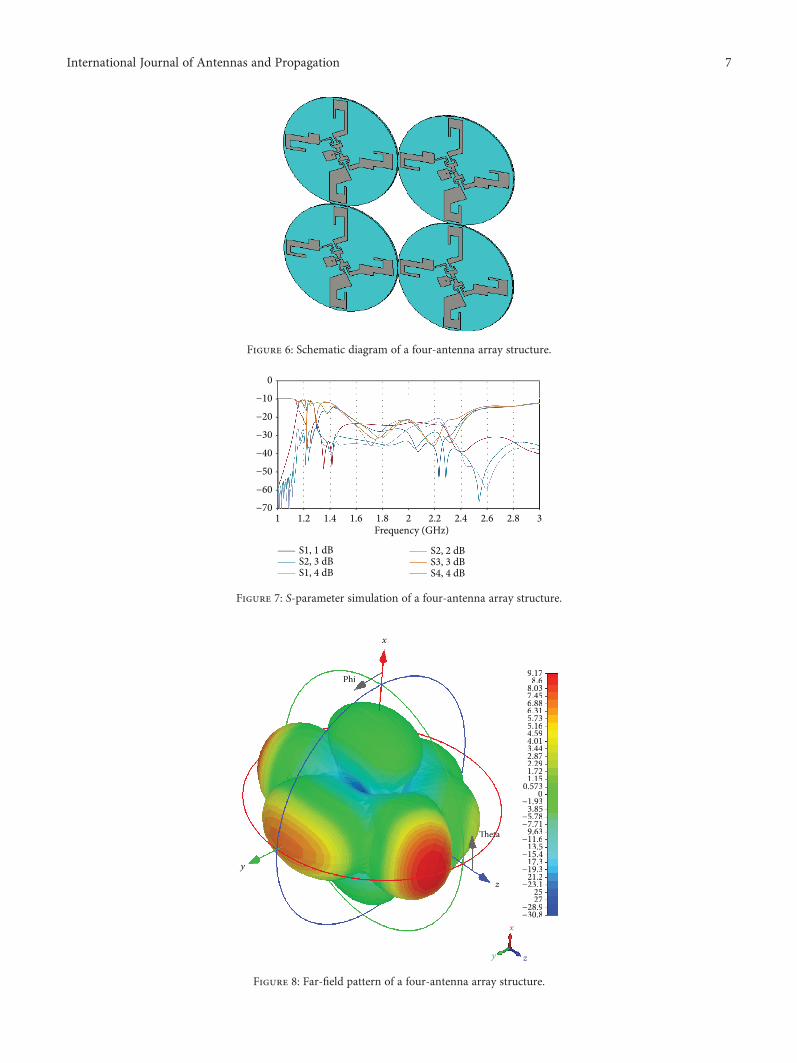
To further verify the proposed antenna, based on theabove simulation results, we employed four elements tobuild an antenna array. As shown in Figure 6, four antennaunits are placed in a plane with an antenna element spacingof 0mm and 0 degree phase angle between adjacent ele-ments. The simulated S-parameter results are presented inFigure 7. Within the operation frequency 1.7–2.7GHz, thereturn loss of antenna elements ( S11 , S22 , S33 , andS44 ) is all below −10dB and the mutual coupling (∣S14∣,
∣S23∣) between any two antenna elements is lower than−20 dB, whichmeans good isolation between any two antennaelements. Also, the far-field pattern of the four-elementantenna is shown in Figure 8. The radiation pattern ofthe antenna system at 2GHz is greater than 8dB andpoints to different directions, which meets the requirementof a robot positioning system antenna for high-precisionpositioning purpose.
4. Measurement
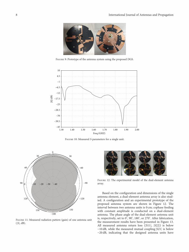
A prototype of the configuration employing the DGS hasbeen fabricated in order to experimentally validate the pro-posed design, as shown in Figure 9. The measured S-parameters are also presented in Figure 10 for comparison.
1
S1, 1 dB
0
−5
−10
−15
−20
−25
−30
−351.2 1.4 1.6 1.8
Frequency (GHz)2.22 2.4 2.6 2.8 3
(a) Antenna unit S-parameter
−15 −10 −5 0 9090
60
Phi = 90
Farfield directivity Abs (phi = 90)
Phi = 27030 30
60
120
150
180
0
150
Theta/degree vs. dBi
120
(b) Radiation pattern of antenna unit
Figure 2: Diagram of the S-parameter and radiation pattern.
4 International Journal of Antennas and Propagation
0° 90°
180° 270°
Figure 3: Schematic diagram of the dual-element antenna array.
−70
−60
−50
−40
−30
−20
−10
0
1 1.2 1.4 1.6 1.8 20° 90°
270°180°
2.2 2.4 2.6 2.8 3
−60
−50
−40
−30
−20
−10
0
1 1.2 1.4 1.6 1.8 2 2.2 2.4 2.6 2.8 3
S1, 1 dBS2, 1 dB
S1, 2 dBS1, 2 dB
−60
−50
−40
−30
−20
−10
0
1 1.2 1.4 1.6 1.8 2 2.2 2.4 2.6 2.8 3
−70
−60
−50
−40
−30
−20
−10
0
1 1.2 1.4 1.6 1.8 2 2.2 2.4 2.6 2.8 3
Figure 4: Simulation of S-parameters of dual-element antenna array structure.
5International Journal of Antennas and Propagation
These results validate that, in the presence of the DGS,the antenna operates within the desired frequency(S11<−10 dB). The resonances of measurement result arevery slightly shifted. These minor discrepancies are due tofabrication imperfections in the manual soldering of the
feeding and shorting pins of the antenna. The antenna radi-ation pattern has been assessed experimentally. It is matchingthe simulation results; the radiation gain of antenna unit isgreater than 2 dB, as presented in Figure 11. The measuredresults match the simulation presented above.
Figure 8: Far-field pattern of a four-antenna array structure.
7International Journal of Antennas and Propagation
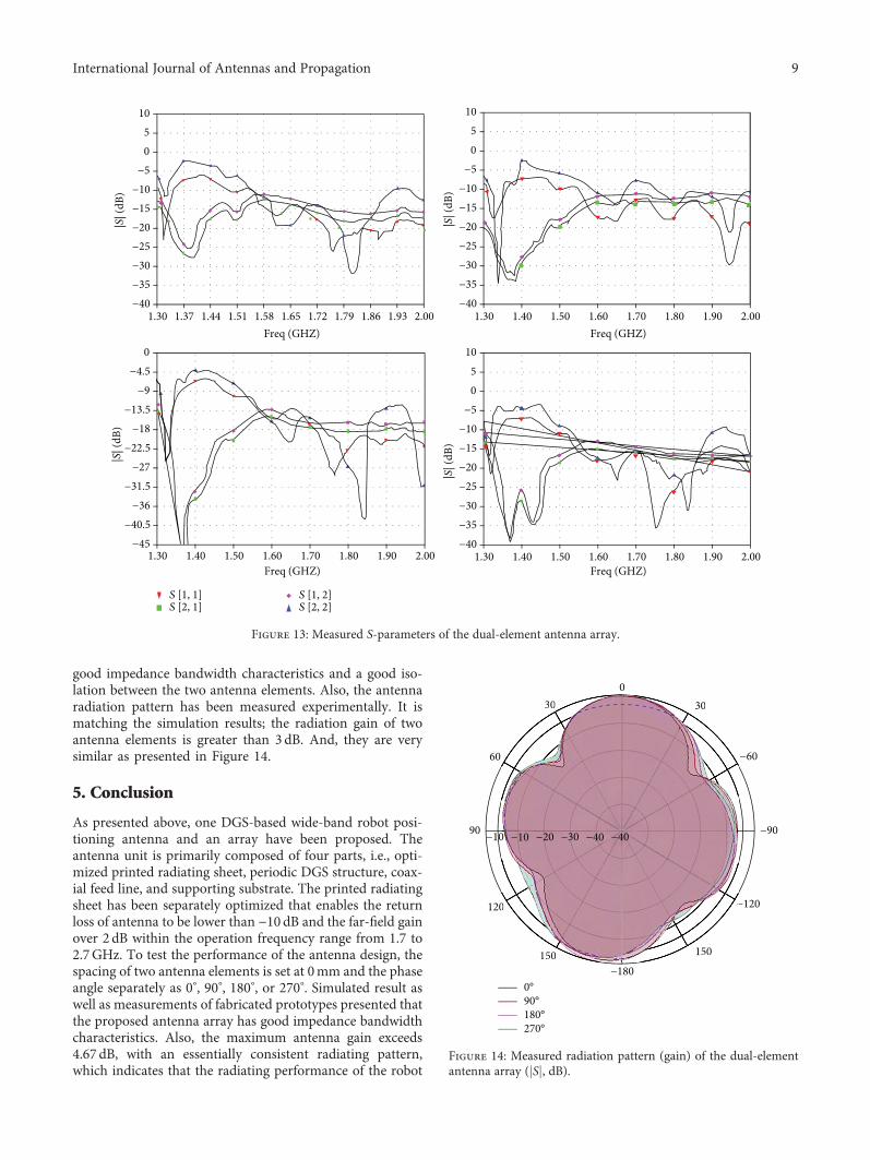
Based on the configuration and dimensions of the singleantenna element, a dual-element antenna array is also stud-ied. A configuration and an experimental prototype of theproposed antenna system are shown in Figure 12. Theinterval between two antenna units is 0 cm; cophase feedingwith constant amplitude is conducted on a dual-elementantenna. The phase angle of the dual-element antenna unitis, respectively, set to 0°, 90°, 180°, or 270°. After fabrication,the measurement results have been presented in Figure 13.All measured antenna return loss ( S11 , S22 ) is below−10 dB, while the measured mutual coupling S21 is below−20 dB, indicating that the designed antenna units have
Figure 9: Prototype of the antenna system using the proposed DGS.
1.30 1.40 1.50 1.60 1.80 1.90 2.001.70Freq (GHZ)
|S| (
dB)
−45
−39.5
−34
−28.5
−23
−17.5
−12
−6.5
−1
4.5
10
Figure 10: Measured S-parameters for a single unit.
0−30
−60
−90
−120
−150−180
0
−30
−150150
120
90
60
30
−10 −20 −30 −40
Figure 11: Measured radiation pattern (gain) of one antenna unit( S , dB).
Figure 12: The experimental model of the dual-element antennaarray.
8 International Journal of Antennas and Propagation
good impedance bandwidth characteristics and a good iso-lation between the two antenna elements. Also, the antennaradiation pattern has been measured experimentally. It ismatching the simulation results; the radiation gain of twoantenna elements is greater than 3dB. And, they are verysimilar as presented in Figure 14.
5. Conclusion
As presented above, one DGS-based wide-band robot posi-tioning antenna and an array have been proposed. Theantenna unit is primarily composed of four parts, i.e., opti-mized printed radiating sheet, periodic DGS structure, coax-ial feed line, and supporting substrate. The printed radiatingsheet has been separately optimized that enables the returnloss of antenna to be lower than −10 dB and the far-field gainover 2 dB within the operation frequency range from 1.7 to2.7GHz. To test the performance of the antenna design, thespacing of two antenna elements is set at 0mm and the phaseangle separately as 0°, 90°, 180°, or 270°. Simulated result aswell as measurements of fabricated prototypes presented thatthe proposed antenna array has good impedance bandwidthcharacteristics. Also, the maximum antenna gain exceeds4.67 dB, with an essentially consistent radiating pattern,which indicates that the radiating performance of the robot
Figure 13: Measured S-parameters of the dual-element antenna array.
90°180°270°
0°
0−30
−60
−90
−120
−150
−180150
120
90
60
30 −30
−
−150150
0
30
−40−30−20−10−10 −40
Figure 14: Measured radiation pattern (gain) of the dual-elementantenna array ( S , dB).
9International Journal of Antennas and Propagation
positioning antenna array designed in this study is stable.Lastly, the simulation results show that the positioningantenna system consisting of quad-element units can operatein the entire working frequency range of 1.7–2.7GHz whileproviding an antenna gain of more than 8dB, having gooddirectionality. In short, the proposed small-sized positioningantenna in this study is simple in design, easy to combine,and with good performance and achieves one compactantenna-feed system. Thus, the proposed structure is suitablefor compact robots.
Data Availability
The data used to support the findings of this study areavailable from the corresponding author upon request.
Conflicts of Interest
The authors declare no conflict of interest.
References
[1] W. Weihua, Research on Positioning Technology of MobileRobot, Huazhong University of Science and Technology,Wuhan, 2005.
[2] N. Guochen, X. Ping, and F. Qi, “Self-localization of mobilerobot based on odometer and PTZ vision,” Computer Applica-tion, vol. 31, no. 10, pp. 2821–2824, 2011.
[3] X. Daisheng, H. Zhiping, S. Rong, and W. Jianyu, “Opticaldesign of laser guided target azimuth detection system,” Optics& Optoelectronic Technology, vol. 2, no. 5, pp. 1–4, 2004.
[4] L. Shaoping, Research on AGV Positioning and GuidanceBased on RFID, Shandong University, Ji Nan, 2011.
[5] B. Hongrui, L. Feng, L. Feng, and W. Donglai, “Attitudecontrol of four rotor aircraft based on UM6 inertial navigationmodule,” Computer & Digital Engineering, vol. 8, pp. 18–21,2012.
[6] L. Xinde, H. Xinhan, and M. I. N. Wang, “Sonar grid mapcreation based on classic DSmT,” Application Research ofComputers, vol. 3, pp. 209–212, 2007.
[7] L. Bing, Research on the Miniaturization of BroadbandBase Station Antenna, University of Electronic Scienceand Technology, Cheng Du, 2013.
[8] W. Maowen, Z. Heng, and G. Baoping, “A novel broadbanddual polarized base station antenna,” Modern Radar, vol. 36,no. 4, pp. 56–60, 2014.
[9] B. G. Duffley, G. A. Morin, M. Mikavica, and Y. M. M. Antar,“A wide-band printed double-sided dipole array,” IEEETransactions on Antennas and Propagation, vol. 52, no. 2,pp. 628–631, 2004.
[10] T. Laohapensaeng and K. Boonying, “Dual polarized micro-strip antenna with high isolation using an inserted slot,” in2011 International Symposium on Intelligent Signal Processingand Communications Systems (ISPACS), pp. 1–5, Chiang Mai,Thailand, December 2011.
[11] F. H. Yang and W. Tang, “A novel low-profile high-gainantenna based on artificial magnetic conductor for LTE appli-cations,” in ISAPE2012, pp. 171–174, Xian, China, October2012.
[12] S. Best and D. Hanna, “Design of a broadband dipole in closeproximity to an EBG ground plane,” IEEE Antennas & Propa-gation Magazine, vol. 50, no. 6, pp. 52–64, 2008.
[13] C. Insik and L. Bomson, “Design of defected ground structuresfor harmonic control of active microstrip antenna,” in IEEEAntennas and Propagation Society International Symposium(IEEE Cat. No.02CH37313), pp. 852–855, San Antonio, TX,USA, June 2002.
[14] J.-S. Park, J.-H. Kim, J.-H. Lee, S.-H. Kim, and S.-H. Myung,“A novel equivalent circuit and modeling method for defectedground structure and its application to optimization of a DGSlowpass filter,” in 2002 IEEE MTT-S International MicrowaveSymposium Digest (Cat. No.02CH37278), pp. 417–420, Seattle,WA, USA, June 2002.
[15] G.-L. Wu, W. Mu, X. W. Dai, and Y. C. Jiao, “Design of noveldual-band bandpass filter with microstrip meander-loop reso-nator and CSRR DGS,” Progress in Electromagnetics Research,vol. 78, pp. 17–24, 2008.
[16] L. H. Weng, Y. C. Guo, X. W. Shi, and X. Q. Chen, “Anoverview on defected ground structure,” Progress in Electro-magnetics Research B, vol. 7, pp. 173–189, 2008.
[17] T. Kokkinos, E. Liakou, and A. P. Feresidis, “Decouplingantenna elements of PIFA arrays on handheld devices,”Electronics Letters, vol. 44, no. 25, pp. 1442–1444, 2008.
[18] Q. Li, A. P. Feresidis, M. Mavridou, and P. S. Hall, “Miniatur-ized double-layer EBG structures for broadband mutualcoupling reduction between UWBmonopoles,” IEEE Transac-tions on Antennas and Propagation, vol. 63, no. 3, pp. 1168–1171, 2015.
10 International Journal of Antennas and Propagation


![Flat Panel Indoor Antenna - Winpluswinplus.com.au/links/UR39677 Bauhn Universal Remote Manual.pdf · Flat Panel Indoor Antenna Universal Remote Control ... [CODE SETUP]. Then release](https://static.documents.pub/doc/80x56/5aff134f7f8b9a864d8fe22a/flat-panel-indoor-antenna-bauhn-universal-remote-manualpdfflat-panel-indoor-antenna.jpg)


