IEEE TRANSACTIONS ON COMMUNICATIONS, VOL. 50, NO. 6, JUNE 2002 1025
Wide-Sense and Strict-Sense Nonblocking Operationof Multicast Multi-log2N Switching Networks
Wojciech Kabacin´ski, Senior Member, IEEE,and Grzegorz Danilewicz
Abstract—Multicast connections are used in broad-bandswitching networks as well as in parallel processing. We con-sider wide-sense and strict-sense nonblocking conditions formulti- log
2switching networks with multicast connections
in this paper. We prove that such networks are wide-sensenonblocking if they are design by vertically stacking at least
2 1 + 2 2 1 planes of a log2
networks together,where1 2 and defines the size of a blocking window
= 2 . For = 2 and even, and for 2the number of planes must be at least 2 1 + 1 and2 + ( 1) 2 1 22 1 + 1, respectively. In thecase of strict-sense nonblocking switching networks, the numberof planes is at least 2. The results obtained in this paper showthat in many cases number of planes in wide-sense nonblockingswitching networks is less than those for = 2 considered in[1]. Number of planes given in the paper is the minimum numberof planes needed for wide-sense nonblocking operation providedthat Algorithm 1 is used for setting up connections. Minimumnumber of planes for such operation in general is still open issue.
SWITCHING networks composed of stages are ofgreat interest in both high-speed electronics and photonic
switching. Such architectures posses many desirable character-istics as almost zero crosstalk, self-routing capability, limitednumbers of stages between each inlet-outlet pair, etc. The majordrawback of these networks is their blocking characteristics. Toobtain nonblocking characteristics, two methods have been pro-posed: horizontal cascading (HC) and vertical stacking (VC)[2], [3].
The HC method results in greater number of stages betweeneach inlet–outlet pair. More stages in a switching networkintroduce greater signal attenuation in the case of photonicswitching network or greater delay in the case of bufferedATM switches. Vertically stacked networks are also calledmulti- switching networks [3], [4]. In VC method thequestion is how many copies of switching networksare to be connected in parallel to obtain nonblocking opera-tion of the whole switching network. The number of copiesneeded in the case of space-division switching networks and
Paper approved by A. Pattavina, the Editor for Switching Architecture Per-formance of the IEEE Communications Society. Manuscript received March 31,2000; revised April 3, 2001, August 3, 2001, and October 18, 2001. This workwas supported by the Polish State Committee for Scientific Research (KBN).
The authors are with the Poznan´ University of Technology, Instituteof Electronics and Telecommunications, 60-965 Poznan´, Poland (e-mail:[email protected]; [email protected]).
Publisher Item Identifier S 0090-6778(02)05545-9.
point-to-point connections was given in [3]–[5]. Nonblockingconditions for multi- switching networks in the multirateenvironment were considered in [6]–[8].
In future communication networks, apart from point-to-pointconnections, many services, for instance video-conference,video-distribution, multi-party communications, etc., willrequire connections from one input to many or even all outputs[9]–[11]. Such connections, called multicast or broadcastconnections, result in blocking characteristics of switchingnetworks. Nonblocking three-stage Clos multicast switchingnetworks require more middle stage switches than networkswith only point-to-point connections [12]–[14]. Blocking char-acteristics of such networks with multicast connections wherealso considered in some papers [15], [16]. Nonblocking multi-cast multi- networks were firstly considered in [17], butresult given in the cited paper constituted the lower bound ofnonblocking operation. Recently, this result was improved in[1], where nonblocking operation of multi- switchingnetworks was given, provided special control algorithm isused. This algorithm is based on the concept called a blockingwindow, where a blocking window contains outputs.
In this paper, strict-sense nonblocking (SSNB) andwide-sense nonblocking (WSNB) switching networks will beconsidered. We will use an algorithm based on a blockingwindow too, but in our case this window consists ofoutputs,where . We will derive a general formula for thenumber of planes needed. We will also show, that the minimumnumber of planes can be obtained forother than .
The paper is organized as follows. In Section II modelused throughout this paper is described. In Section III theconcept called blocking window is given as well as pathrouting algorithm is presented. In the next Section WSNBswitching networks are considered. Nonblocking conditionsfor are given in Theorem 1 and the sameconditions for are proved in Theorem 2.Numerical examples of these Theorems are shown in Section V.Strict-sense nonblocking switching networks are considered inSection VI followed by some comparison and conclusions.
II. M ODEL DESCRIPTION
A. Switching Network Architecture
A multi- network is constructed by vertically stackingcopies of networks. Three topologically equivalent
networks were considered, wheredenotes the numberof inlets/outlets, , namely banyan, baseline, and shuffleswitching networks. These networks are composed of 2
2 switches and are called planes. In further part of the paper
1026 IEEE TRANSACTIONS ON COMMUNICATIONS, VOL. 50, NO. 6, JUNE 2002
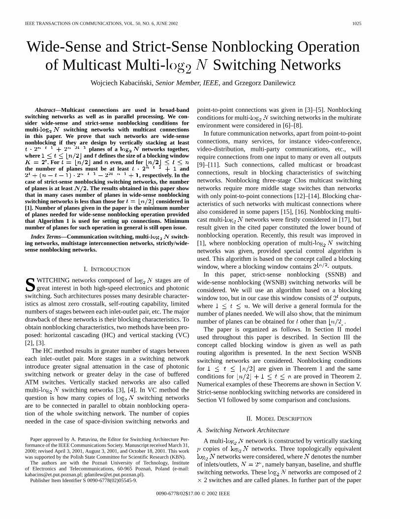
Fig. 1. An example of one plane of multi-log N network withN = 16.
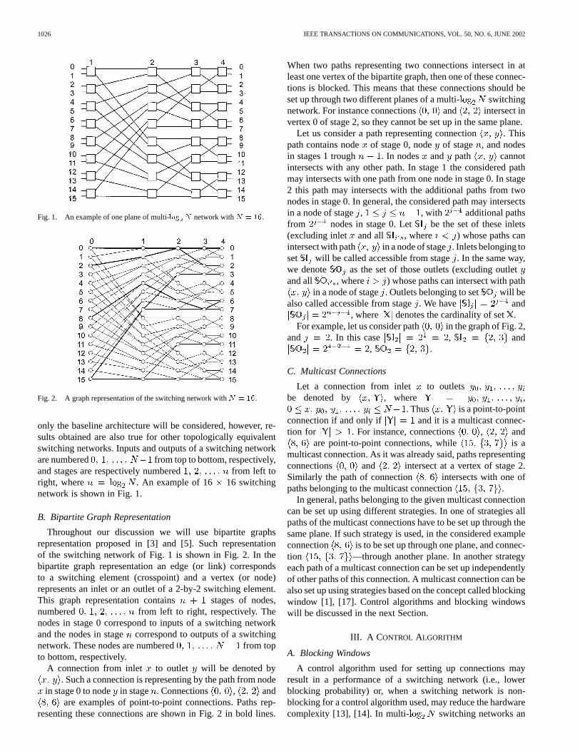
Fig. 2. A graph representation of the switching network withN = 16.
only the baseline architecture will be considered, however, re-sults obtained are also true for other topologically equivalentswitching networks. Inputs and outputs of a switching networkare numbered from top to bottom, respectively,and stages are respectively numbered from left toright, where . An example of 16 16 switchingnetwork is shown in Fig. 1.
B. Bipartite Graph Representation
Throughout our discussion we will use bipartite graphsrepresentation proposed in [3] and [5]. Such representationof the switching network of Fig. 1 is shown in Fig. 2. In thebipartite graph representation an edge (or link) correspondsto a switching element (crosspoint) and a vertex (or node)represents an inlet or an outlet of a 2-by-2 switching element.This graph representation contains stages of nodes,numbered from left to right, respectively. Thenodes in stage 0 correspond to inputs of a switching networkand the nodes in stagecorrespond to outputs of a switchingnetwork. These nodes are numbered from topto bottom, respectively.
A connection from inlet to outlet will be denoted by. Such a connection is representing by the path from node
in stage 0 to node in stage . Connections , andare examples of point-to-point connections. Paths rep-
resenting these connections are shown in Fig. 2 in bold lines.
When two paths representing two connections intersect in atleast one vertex of the bipartite graph, then one of these connec-tions is blocked. This means that these connections should beset up through two different planes of a multi- switchingnetwork. For instance connections and intersect invertex 0 of stage 2, so they cannot be set up in the same plane.
Let us consider a path representing connection . Thispath contains node of stage 0, node of stage , and nodesin stages 1 trough . In nodes and path cannotintersects with any other path. In stage 1 the considered pathmay intersects with one path from one node in stage 0. In stage2 this path may intersects with the additional paths from twonodes in stage 0. In general, the considered path may intersectsin a node of stage, , with additional pathsfrom nodes in stage 0. Let be the set of these inlets(excluding inlet and all , where ) whose paths canintersect with path in a node of stage. Inlets belonging toset will be called accessible from stage. In the same way,we denote as the set of those outlets (excluding outletand all , where ) whose paths can intersect with path
in a node of stage. Outlets belonging to set will bealso called accessible from stage. We have and
, where denotes the cardinality of set.For example, let us consider path in the graph of Fig. 2,
and . In this case , and, .
C. Multicast Connections
Let a connection from inlet to outletsbe denoted by , where ,
. Thus is a point-to-pointconnection if and only if and it is a multicast connec-tion for . For instance, connections , and
are point-to-point connections, while is amulticast connection. As it was already said, paths representingconnections and intersect at a vertex of stage 2.Similarly the path of connection intersects with one ofpaths belonging to the multicast connection .
In general, paths belonging to the given multicast connectioncan be set up using different strategies. In one of strategies allpaths of the multicast connections have to be set up through thesame plane. If such strategy is used, in the considered exampleconnection is to be set up through one plane, and connec-tion —through another plane. In another strategyeach path of a multicast connection can be set up independentlyof other paths of this connection. A multicast connection can bealso set up using strategies based on the concept called blockingwindow [1], [17]. Control algorithms and blocking windowswill be discussed in the next Section.
III. A C ONTROL ALGORITHM
A. Blocking Windows
A control algorithm used for setting up connections mayresult in a performance of a switching network (i.e., lowerblocking probability) or, when a switching network is non-blocking for a control algorithm used, may reduce the hardwarecomplexity [13], [14]. In multi- switching networks an
KABACIN SKI AND DANILEWICZ: WSNB AND SSNB OPERATION OF MULTICASE MULTI- SWITCHING NETWORKS 1027
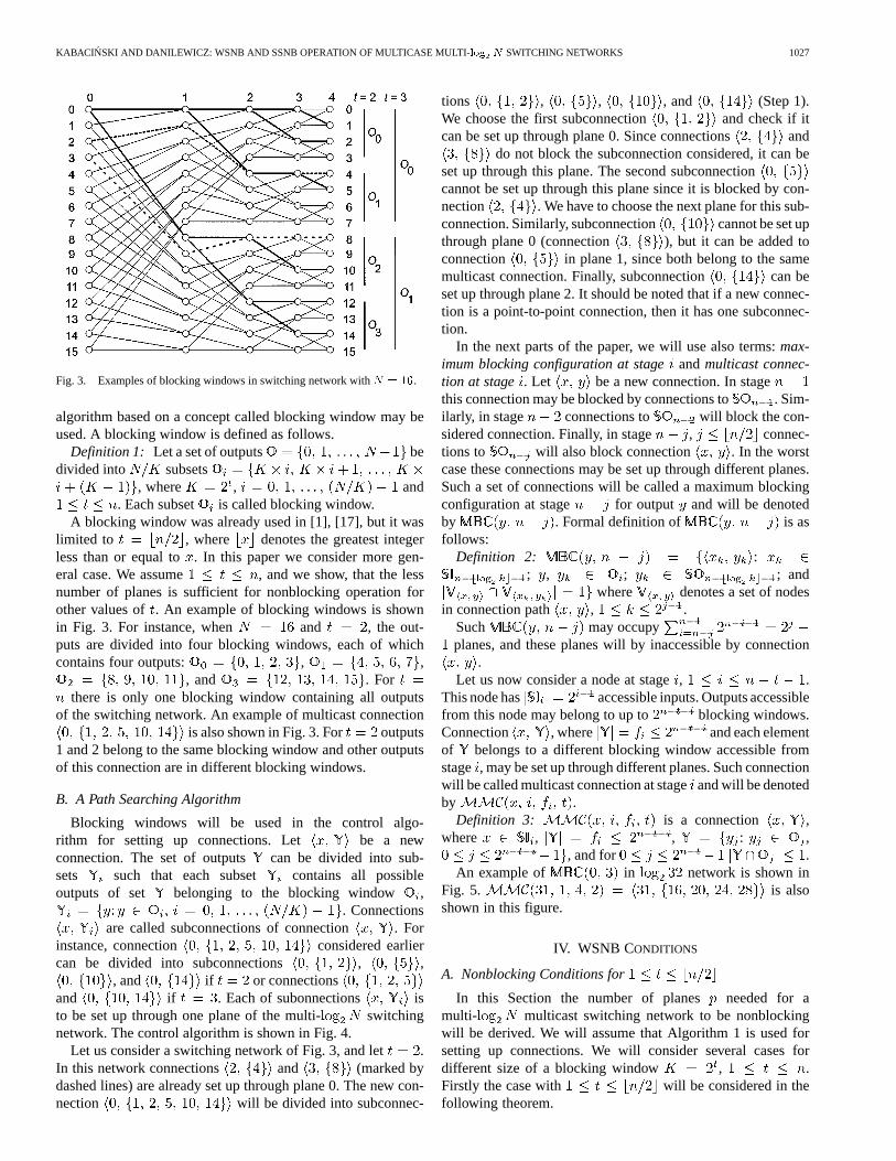
Fig. 3. Examples of blocking windows in switching network withN = 16.
algorithm based on a concept called blocking window may beused. A blocking window is defined as follows.
Definition 1: Let a set of outputs bedivided into subsets
, where , and. Each subset is called blocking window.
A blocking window was already used in [1], [17], but it waslimited to , where denotes the greatest integerless than or equal to. In this paper we consider more gen-eral case. We assume , and we show, that the lessnumber of planes is sufficient for nonblocking operation forother values of . An example of blocking windows is shownin Fig. 3. For instance, when and , the out-puts are divided into four blocking windows, each of whichcontains four outputs: , ,
, and . Forthere is only one blocking window containing all outputs
of the switching network. An example of multicast connectionis also shown in Fig. 3. For outputs
1 and 2 belong to the same blocking window and other outputsof this connection are in different blocking windows.
B. A Path Searching Algorithm
Blocking windows will be used in the control algo-rithm for setting up connections. Let be a newconnection. The set of outputs can be divided into sub-sets such that each subset contains all possibleoutputs of set belonging to the blocking window ,
. Connectionsare called subconnections of connection . For
instance, connection considered earliercan be divided into subconnections , ,
, and if or connectionsand if . Each of subonnections isto be set up through one plane of the multi- switchingnetwork. The control algorithm is shown in Fig. 4.
Let us consider a switching network of Fig. 3, and let .In this network connections and (marked bydashed lines) are already set up through plane 0. The new con-nection will be divided into subconnec-
tions , , , and (Step 1).We choose the first subconnection and check if itcan be set up through plane 0. Since connections and
do not block the subconnection considered, it can beset up through this plane. The second subconnectioncannot be set up through this plane since it is blocked by con-nection . We have to choose the next plane for this sub-connection. Similarly, subconnection cannot be set upthrough plane 0 (connection ), but it can be added toconnection in plane 1, since both belong to the samemulticast connection. Finally, subconnection can beset up through plane 2. It should be noted that if a new connec-tion is a point-to-point connection, then it has one subconnec-tion.
In the next parts of the paper, we will use also terms:max-imum blocking configuration at stageandmulticast connec-tion at stage . Let be a new connection. In stagethis connection may be blocked by connections to . Sim-ilarly, in stage connections to will block the con-sidered connection. Finally, in stage , connec-tions to will also block connection . In the worstcase these connections may be set up through different planes.Such a set of connections will be called a maximum blockingconfiguration at stage for output and will be denotedby . Formal definition of is asfollows:
Definition 2: :; , ; ; and
where denotes a set of nodesin connection path , .
Such may occupyplanes, and these planes will by inaccessible by connection
.Let us now consider a node at stage, .
This node has accessible inputs. Outputs accessiblefrom this node may belong to up to blocking windows.Connection , where and each elementof belongs to a different blocking window accessible fromstage , may be set up through different planes. Such connectionwill be called multicast connection at stageand will be denotedby .
Definition 3: is a connection ,where , , : ,
, and for .An example of in network is shown in
Fig. 5. is alsoshown in this figure.
IV. WSNB CONDITIONS
A. Nonblocking Conditions for
In this Section the number of planes needed for amulti- multicast switching network to be nonblockingwill be derived. We will assume that Algorithm 1 is used forsetting up connections. We will consider several cases fordifferent size of a blocking window , .Firstly the case with will be considered in thefollowing theorem.
1028 IEEE TRANSACTIONS ON COMMUNICATIONS, VOL. 50, NO. 6, JUNE 2002
Fig. 4. Algorithm 1 for setting up connections.
Theorem 1: Consider a multi- switchingnetwork created by vertically stackingcopies of net-work together. Then the network is WSNB forprovided that Algorithm 1 is used if and only if:
for and when is odd
for when is even
(1)
Proof: Let a new connection is to be added in aswitching network. It may be a point-to-point connection ora subconnection of a multicast connection. This connection is
blocked in one plane if another connection is already set upthrough one of nodes belonging to the path between inputand output . In stage connection may be blockedby connections , where , and . Instage this connection may be blocked by connections
, where , and . Finally, in stagethis connection may be blocked by connections ,
where , and . These connections constituteand in the worst case they may be set up trough
different planes. So planes will be inaccessible by the con-nection , where
(2)
KABACIN SKI AND DANILEWICZ: WSNB AND SSNB OPERATION OF MULTICASE MULTI- SWITCHING NETWORKS 1029
Fig. 5. An example of (0; 3) andMMC(31; 1; 4; 2).
We have now all outputs of the blocking window con-taining output occupied. Output is the desired output andconnections to other outputs of the blocking window are setup through different planes. Since there is no free outputsin the blocking window and each connection to outputs inblocking window is set up through different plane, then thereis no possible to occupy more than planes. So it is theworst case for . On the other hand we have inputsaccessible from stage 1, and from this stage we can get tooutputs belonging to different blocking windows, butoutputs in one blocking window are already occupied. We canconstruct . Similarly, we canconstruct . In general we mayhave for . Theseconnections will occupyoutputs in one blocking window (accessible from nodes ofall stages from 1 to ). Since each blocking windowcontains outputs, this means that there are still free outputsin this blocking window. However, for and evenwe have . It means that outputs of the setbelong to the same blocking window as outputandcannot be considered. In the worst case each subconnection ofconnection from input with
may be set up through different planes, so
(3)
planes may be occupied by these connections.
When or when and is odd we mayalso consider and
. However, since, then there is only one output free in blocking window
accessible from nodes of all stages from 1 to, so we may haveonly one connection from . In this case we have
(4)
Since all subconnections of s are point-to-point connec-tions (this means that they occupy as little outputs in blockingwindow as possible), each of them is set up through differentplanes, and those s occupy all possible outputs inblocking windows accessible from considered stages then thisis a worst case for .
In the worst case sets of and planes are disjoint and onemore plane is needed for setting up the new connection.
For and for and odd we have
(5)
(6)
For and even, we have
(7)
(8)
Taking into account that for and even we have, we finally get
(9)
Necessity can be proved by showing the set of events leadingto occupancy of planes, where is given by (1). It should benoted that this set of events may be constructed in different waydepending on and . We will show here the case when
and is odd. Let us also assume that the new connectionto be set up is .
———–We have: , . Let
, , where .For to do
set up connections .
1030 IEEE TRANSACTIONS ON COMMUNICATIONS, VOL. 50, NO. 6, JUNE 2002
These connections are set up through plane 0. Now in thisplane only subconnection can be set up. For othersubconnections of this multicast connection this plane is inac-cessible.
For to doset up connections ;set up connection ;disconnect ;set up connection .
It should be noted that connection foris in conflict with connection
in plane 0. So it has to be set up in plane 1. All otherconnections will also be set up in plane 1. Now in this plane onlysubconnection can be set up.
By analogy we may set up connections which will blocksubconnection in plane 2, and so forth. Finally,
is set up throughplanes (for we have ), and all otherconnections are disconnected.
In a current state of the switching network following set ofevents will cause that a path for a next connection will be firstlychecked in plane .
set up connection in plane ;set up connection ;disconnect connection .
In the similar way we have: , and let
and. Each
of these connections will occupy planes. We have:
(10)
From (4), since is odd and , we have:
(11)
All planes are inaccessible by connection . Followingset of events causes that every time connection has to beset up through the next plane:
For to doFor to do
set up connection ;set up connection ;disconnect connection ;set up connection ;disconnect connection .
This means that next planes will be inaccessible to con-nection , where
(12)
———–So all together
(13)
planes are necessary for a switching network to be nonblocking.From (1), for and odd we have:
(14)
It should be noted that for even and we have:
(15)
It is the same result as in [1].It is not difficult to show, that the number of planes is growing
when is getting smaller, so the minimum number of planes isobtained for the biggest value of, i.e., for .
B. Nonblocking Conditions for
Now let us assume that . Before we moveto the nonblocking conditions in this case, let us give one moredefinition.
Definition 4: Let a blocking window be divided intosubsets
where
Each subset is called a subblocking window.Theorem 2: Consider a multi- switching
network created by vertically stackingcopies of net-work together. Then the network is WSNB for
provided that Algorithm 1 is used if and only if:
(16)
Proof: Similarly as in Theorem 1 the proof will be basedon constructing the worst state of a switching network. Let anew connection is to be set up, where belongs to oneblocking window, and let . In this case a blockingwindow contains s.
Even : Let , and . We may constructwhich will occupy
(17)
KABACIN SKI AND DANILEWICZ: WSNB AND SSNB OPERATION OF MULTICASE MULTI- SWITCHING NETWORKS 1031
planes, and all outputs in are busy. Since for evenwehave , than all inputs accessible fromstage are also busy and cannot be considered in nextconnections. Connections to outlets of may occupyplanes, where
(18)
When and , than these planes will be inac-cessible by . In we have still free outputs.In stages numbered from 1 to we have
accessible inputs. It means that there will be pos-sible to set up in each of these stages for all accessibleinputs. When all outputs in the blocking window are al-ready assigned. For next may be considered.
Connections in and occupy in-puts of , so we have still inputs free.We may construct two : and
, , andthese connections will use
(19)
Index , in means that connections in planesoccupy outputs in .
All outputs in are now used and we have still freeoutputs in . So we may consider the next in stage
.Let stage , , is considered. In this section,
we have and . Connec-tions in s of previous stages will occupy inputsaccessible from stage so we have still
free inputs. These inputs may be used for constructings in stage . We may construct
such s. Each in stage will occupyoutputs and one output
in . In one we may construct
s. So s in stage will occupy outputs in nexts. These s are
numbered from to . In this way next
(20)
planes will be inaccessible by a connection . This timeconnections in planes, occupy outputs insubblocking windows from to .
Finally, in stage number of s which can be occupiedby s is , however, in this case we have only
s with free outputs. So, the s in stagewill occupy
(21)
planes, and all outputs in the blocking window are assigned ex-cept outputs in . Connections in planes oc-cupy subblocking windows from to . Theway was calculated is shown in Fig. 6.
In stages numbered from 1 to we may now constructs for each input and, by analogy to Theorem 1, these
connections may occupy
(22)
In the worst case these sets are disjoint and one more plane isneeded for connection , so in general we can write:
It should be however noticed, that for (i.e., ),we have only two s so we have in this case
(23)
For we have
(24)
1032 IEEE TRANSACTIONS ON COMMUNICATIONS, VOL. 50, NO. 6, JUNE 2002
(a) (b)
(c) (d)
(e)
Fig. 6. Number of planes in the proof of Theorem 2,n even, (a)p , (b) p , (c) p , (d) p , (e)p .
For we can write (25)
It should be noticed, that if in (25) we put we obtain(24) and if than (25) becomes (23). Taking also intoaccount that and is even we have
It should be also pointed out, that for ,and but formula (16) is true in
this case.For odd construction of the worst case scenario is similar
to that for even. However, in this case, outputs in two s
KABACIN SKI AND DANILEWICZ: WSNB AND SSNB OPERATION OF MULTICASE MULTI- SWITCHING NETWORKS 1033
will be occupied by two s, so planescan be inaccessible for a new connection. For ablocking window is composed of two s and all outputs inthis blocking window are occupied. This means that we cannotset up s to all blocking windows available from the nodein stage , . So is given by
(26)
For outputs in the third may be occupiedby connections constructing andconnections to outputs accessible from stage .This connections will occupy
Also for odd we have . The total number ofplanes is in this case also given by (16).
Necessity can be proved by showing the set of events leadingto occupancy of planes, where is given by (16). Let us as-sume that connection , is to be set up. Similarly asin Theorem 1 in stage 1 we may construct .Also by analogy next s can be constructed in next stagesup to stage . This connections will occupy planes,where is given by (26). Also by analogy to the last part ofthe set of events for Theorem 1 we may construct connectionwhich will occupy planes, where is given by (17). Nowevery time connection ,is to be set up, it has to be set up through the next plane. So wemay cause that next planes will be inaccessible by connec-tion . The next connection ,
will have to be set upthrough the next plane, and so forth. Finally, in this way con-nection will be blocked in already occupied planes andone more plane is needed.
In Theorems 1 and 2 we have proved nonblocking conditionsfor different . Now the question is for which the number ofplanes is minimized.
C. Minimum Number of Planes
The number of planes for reaches minimumfor and it is given by (15) for even, and by (14) for
odd. For the number of planes is given by(16). If is even and we have
(27)
TABLE ISET OF EVENTS IN 32� 32 SWITCHING NETWORK
By checking for we can conclude, that forless number of planes is needed for
than for . For we have and.
For odd we have
and
It can be checked, that for, and for we have always
. For instance when we haveand .
V. NUMERICAL EXAMPLES
We will give now an example showing that the number ofplanes given in Theorem 1 is necessary. Let us assume that
and in this case, for we have. The set of events leading to the occupancy of 9
planes is given in Table I. Connections marked by asterisk areconnections which still exist when the new connectionis to be set up and it must use plane 8, since other planes areinaccessible for this connection.
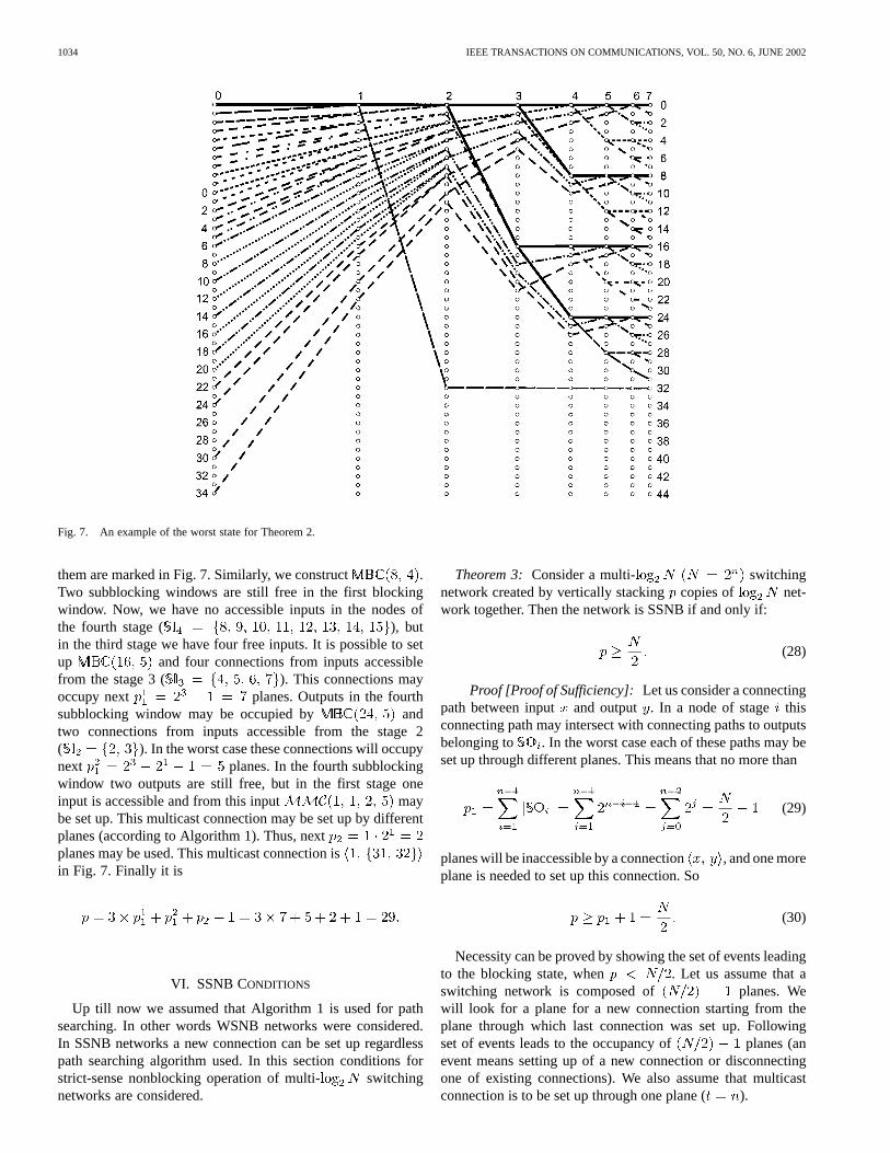
An example of the worst state in switching networkfor is shown in Fig. 7. This is a case given by Theorem 2.Each blocking window contains outputs and each ofsubblocking windows has outputs. Let us assumethat the considered connection is the multicast connection
. There is possible to set up and. Each of two s may occupies up to different
planes. So, we have . Connections whichconstitute are connections , ,
, , , and . All of
1034 IEEE TRANSACTIONS ON COMMUNICATIONS, VOL. 50, NO. 6, JUNE 2002
Fig. 7. An example of the worst state for Theorem 2.
them are marked in Fig. 7. Similarly, we construct .Two subblocking windows are still free in the first blockingwindow. Now, we have no accessible inputs in the nodes ofthe fourth stage ( ), butin the third stage we have four free inputs. It is possible to setup and four connections from inputs accessiblefrom the stage 3 ( ). This connections mayoccupy next planes. Outputs in the fourthsubblocking window may be occupied by andtwo connections from inputs accessible from the stage 2( ). In the worst case these connections will occupynext planes. In the fourth subblockingwindow two outputs are still free, but in the first stage oneinput is accessible and from this input maybe set up. This multicast connection may be set up by differentplanes (according to Algorithm 1). Thus, nextplanes may be used. This multicast connection isin Fig. 7. Finally it is
VI. SSNB CONDITIONS
Up till now we assumed that Algorithm 1 is used for pathsearching. In other words WSNB networks were considered.In SSNB networks a new connection can be set up regardlesspath searching algorithm used. In this section conditions forstrict-sense nonblocking operation of multi- switchingnetworks are considered.
Theorem 3: Consider a multi- switchingnetwork created by vertically stackingcopies of net-work together. Then the network is SSNB if and only if:
(28)
Proof [Proof of Sufficiency]: Let us consider a connectingpath between input and output . In a node of stage thisconnecting path may intersect with connecting paths to outputsbelonging to . In the worst case each of these paths may beset up through different planes. This means that no more than
(29)
planes will be inaccessible by a connection , and one moreplane is needed to set up this connection. So
(30)
Necessity can be proved by showing the set of events leadingto the blocking state, when . Let us assume that aswitching network is composed of planes. Wewill look for a plane for a new connection starting from theplane through which last connection was set up. Followingset of events leads to the occupancy of planes (anevent means setting up of a new connection or disconnectingone of existing connections). We also assume that multicastconnection is to be set up through one plane ( ).
KABACIN SKI AND DANILEWICZ: WSNB AND SSNB OPERATION OF MULTICASE MULTI- SWITCHING NETWORKS 1035
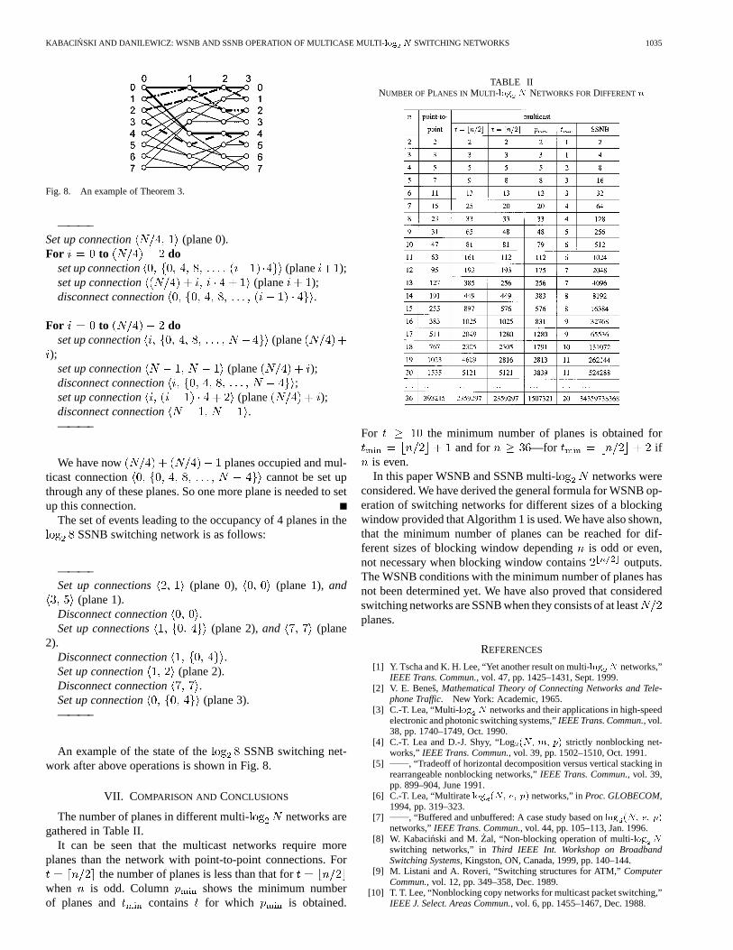
Fig. 8. An example of Theorem 3.
———–Set up connection (plane 0).For to do
set up connection (plane );set up connection (plane );disconnect connection .
For to doset up connection (plane
);set up connection (plane );disconnect connection ;set up connection (plane );disconnect connection .———–
We have now planes occupied and mul-ticast connection cannot be set upthrough any of these planes. So one more plane is needed to setup this connection.
The set of events leading to the occupancy of 4 planes in theSSNB switching network is as follows:
———–Set up connections (plane 0), (plane 1),and
(plane 1).Disconnect connection .Set up connections (plane 2),and (plane
2).Disconnect connection .Set up connection (plane 2).Disconnect connection .Set up connection (plane 3).———–
An example of the state of the SSNB switching net-work after above operations is shown in Fig. 8.
VII. COMPARISON AND CONCLUSIONS
The number of planes in different multi- networks aregathered in Table II.
It can be seen that the multicast networks require moreplanes than the network with point-to-point connections. For
the number of planes is less than that forwhen is odd. Column shows the minimum numberof planes and contains for which is obtained.
TABLE IINUMBER OF PLANES IN MULTI-log N NETWORKS FORDIFFERENTn
For the minimum number of planes is obtained forand for —for if
is even.In this paper WSNB and SSNB multi- networks were
considered. We have derived the general formula for WSNB op-eration of switching networks for different sizes of a blockingwindow provided that Algorithm 1 is used. We have also shown,that the minimum number of planes can be reached for dif-ferent sizes of blocking window dependingis odd or even,not necessary when blocking window contains outputs.The WSNB conditions with the minimum number of planes hasnot been determined yet. We have also proved that consideredswitching networks are SSNB when they consists of at leastplanes.
REFERENCES
[1] Y. Tscha and K. H. Lee, “Yet another result on multi-log N networks,”IEEE Trans. Commun., vol. 47, pp. 1425–1431, Sept. 1999.
[2] V. E. Benes, Mathematical Theory of Connecting Networks and Tele-phone Traffic. New York: Academic, 1965.
[3] C.-T. Lea, “Multi-log N networks and their applications in high-speedelectronic and photonic switching systems,”IEEE Trans. Commun., vol.38, pp. 1740–1749, Oct. 1990.
[4] C.-T. Lea and D.-J. Shyy, “Log(N; m; p) strictly nonblocking net-works,” IEEE Trans. Commun., vol. 39, pp. 1502–1510, Oct. 1991.
[5] , “Tradeoff of horizontal decomposition versus vertical stacking inrearrangeable nonblocking networks,”IEEE Trans. Commun., vol. 39,pp. 899–904, June 1991.
[7] , “Buffered and unbuffered: A case study based onlog (N; e; p)networks,”IEEE Trans. Commun., vol. 44, pp. 105–113, Jan. 1996.
[8] W. Kabacinski and M.Zal, “Non-blocking operation of multi-log N
switching networks,” inThird IEEE Int. Workshop on BroadbandSwitching Systems, Kingston, ON, Canada, 1999, pp. 140–144.
[9] M. Listani and A. Roveri, “Switching structures for ATM,”ComputerCommun., vol. 12, pp. 349–358, Dec. 1989.
[10] T. T. Lee, “Nonblocking copy networks for multicast packet switching,”IEEE J. Select. Areas Commun., vol. 6, pp. 1455–1467, Dec. 1988.
1036 IEEE TRANSACTIONS ON COMMUNICATIONS, VOL. 50, NO. 6, JUNE 2002
[11] J. Y. Hui, Switching and Traffic Theory for Integrated Broadband Net-works. Boston, MA: Kluwer, 1990.
[12] C. Clos, “A study of nonblocking switching networks,”Bell Syst. Tech.J., pp. 406–424, 1953.
[13] F. K. Hwang and A. Jajszczyk, “On nonblocking multiconnectionnetworks,”IEEE Trans. Commun., vol. COM-34, pp. 1038–1041, Oct.1986.
[14] Y. Yang and M. Masson, “Non-blocking broadcast switching networks,”IEEE Trans. Computers, vol. 40, pp. 1005–1015, Sept. 1991.
[15] Y. Yang and J. Wang, “On blocking probability of multicast networks,”IEEE Trans. Commun., vol. 46, pp. 957–968, July 1998.
[16] M. Stasiak, P. Zwierzykowski, and M. G˛labowski, “Blocking proba-bility in the multi-service switching networks with multicast traffic,” in10th IEEE Mediterranean Electrotechnical Conf.—MELECON, vol. 2,(Cypr), 2000, pp. 868–871.
[17] Y. Tscha and K. H. Lee, “Non-blocking conditions for multi-log N
multiconnection networks,” in Proc. GLOBECOM, 1992, pp.1600–1604.
Wojciech Kabacinski (A’94–SM’01) received theM.Sc., Ph.D., and D.Sc. degrees in communicationfrom Poznan´ University of Technology, Poland, in1983, 1988, and 1999, respectively.
Since 1983, he has been working in the Instituteof Electronics and Telecommunications, Poznan´University of Technology, where he currently isan Associate Professor. His scientific interestscover broad-band switching networks and photonicswitching. He has published three books, 78 papers,and holds 10 patents.
Prof. Kabacin´ski is a member of the IEEE Communications Society and theAssociation of Polish Electrical Engineers.
Grzegorz Danilewiczwas born in Poznan´, Poland,on March 15, 1968. He received the M.Sc. and Ph.D.degrees in telecommunications from the Poznan´ Uni-versity of Technology, Poland, in 1993 and 2001, re-spectively.
Since 1993, he has been working in the In-stitute of Electronics, Poznan´ University of Tech-nology, where he currently is an Assistant Professor.His scientific interests cover photonic broad-bandswitching systems with special regard to the real-ization of multicast connections in such systems.