Wideband holographic correction of an aberratedtelescope objective
Jesper Munch, Ralph Wuerker, and Lee Heflinger
The imaging properties of a holographically corrected telescope are presented for broadband illuminationusing a single grating to correct for dispersion. High quality, broadband images approaching the perform-ance of diffraction limited instruments are obtained from severely aberrated refractor and reflector telescopeobjectives.
1. Introduction
In a recent paperl we described a method for correct-ing aberrations in a telescope objective using hologra-phy. The concept is similar to that described by Ko-gelnik and Pennington2 for correcting distortions dueto diffuse aberrators. It differs from other single-pass(one-way) approaches described in Refs. 3-7 because itdoes not attempt to correct for intermediate atmo-spheric distortions and does not make use of activeillumination of the object. Instead, the concept makesuse of a local beacon laser to write an image phasehologram of the aberrator, and subsequent aberration-corrected images of a distant object are formed byreconstructing this hologram with the aberrated objectwave. The concept is ideally suited for lightweightspace-based telescopes, and can also be used with realtime holography or phase conjugation. We describedexperimental results indicating that the concept couldbe used to create a telescope with a useful field of viewas well as with a nonzero bandwidth. We shall reporthere on recent experiments demonstrating a practicalrealization of a fairly wide-band corrected telescopebuilt using low quality, aberrated telescope objectives.
II. Wide Band Concept
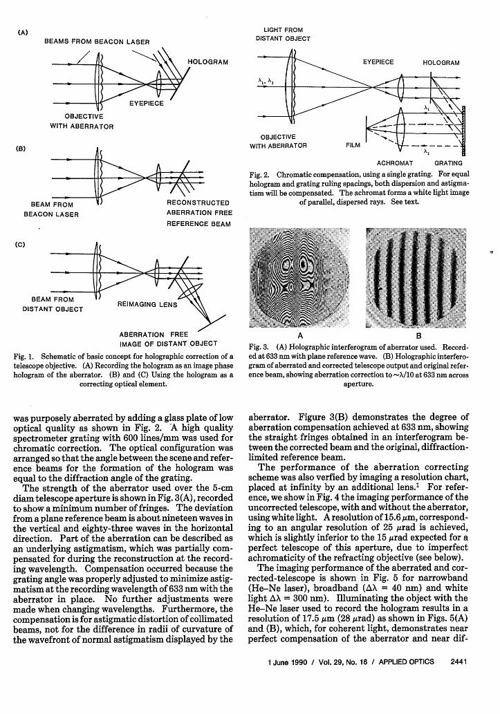
The basic monochromatic concept of Ref. 1 is sum-marized in Fig. 1, illustrating how the correcting holo-gram is formed and used. When the hologram is re-constructed with broadband illumination, it behavesas a dispersing element resulting in a blurred image.
Ralph Wuerker is with University of California, Los Angeles,Physics Department, Los Angeles, California 90024-1547; the otherauthors are with TRW Space & Technology Group, 1 Space Park,Redondo Beach, California 90278.
In Ref. 1 we indicated that this chromatic degradationcould be partially compensated by using additionalgratings as described in Refs. 8 and 9, and demonstrat-ed that the degree of correction obtained with broad-band illumination depended on the magnitude of theaberration and the shift in wavelength. The lack ofperfect compensation for broadband illuminationarises because the strength of the aberrator is mea-sured and recorded on the compensating hologram as aphase shift (number of wavelengths) of the beaconlaser, which, for a given aberration, cannot necessarilybe the correct compensation for a different wave-length.
In this work we have added chromatic compensationfor the dispersion of the hologram, using a single grat-ing as shown in Fig. 2. The telescope is set up in such away that the grating spacing of the compensating holo-gram is equal to that of the grating. This simpleconfiguration works because white light from a distantpoint source is dispersed by the hologram into a chro-matic fan, which the grating redirects into parallel, butdisplaced chromatic components as shown. Using anachromatic lens the parallel beams are focused to apoint, which is the white light image of the distantpoint. This approach also compensates for the astig-matic distortion which occurs when a hologram is re-constructed with a wavelength different from thatused in the recording process.10 This compensationoccurs because the beams impinging on the hologramand emerging from the grating are parallel for identicalline spacings, thus restoring the original transversedimension of each chromatic component. The per-formance of telescopes using this concept is discussedbelow.
111. Refracting Telescope
The refracting telescope was set up as described inRef. 1 using a high quality telescope objective which
Fig. 2. Chromatic compensation, using a single grating. For equalhologram and grating ruling spacings, both dispersion and astigma-tism will be compensated. The achromat forms a white light image
of parallel, dispersed rays. See text.ABERRATION FREE
REFERENCE BEAM
BEAM FROM REIMAGING LENSDISTANT OBJECT
ABERRATION FREEIMAGE OF DISTANT OBJECT
Fig. 1. Schematic of basic concept for holographic correction of atelescope objective. (A) Recording the hologram as an image phasehologram of the aberrator. (B) and (C) Using the hologram as a
correcting optical element.
was purposely aberrated by adding a glass plate of lowoptical quality as shown in Fig. 2. 'A high qualityspectrometer grating with 600 lines/mm was used forchromatic correction. The optical configuration wasarranged so that the angle between the scene and refer-ence beams for the formation of the hologram wasequal to the diffraction angle of the grating.
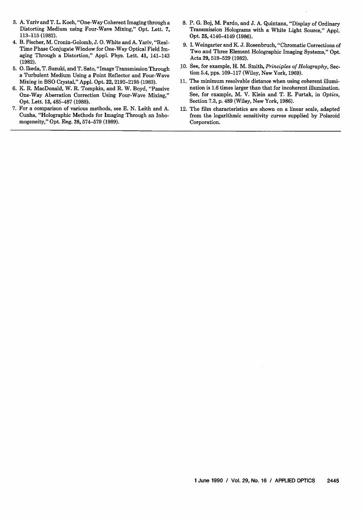
The strength of the aberrator used over the 5-cmdiam telescope aperture is shown in Fig. 3(A), recordedto show a minimum number of fringes. The deviationfrom a plane reference beam is about nineteen waves inthe vertical and eighty-three waves in the horizontaldirection. Part of the aberration can be described asan underlying astigmatism, which was partially com-pensated for during the reconstruction at the record-ing wavelength. Compensation occurred because thegrating angle was properly adjusted to minimize astig-matism at the recording wavelength of 633 nm with theaberrator in place. No further adjustments weremade when changing wavelengths. Furthermore, thecompensation is for astigmatic distortion of collimatedbeams, not for the difference in radii of curvature ofthe wavefront of normal astigmatism displayed by the
A B
Fig. 3. (A) Holographic interferogram of aberrator used. Record-ed at 633 nm with plane reference wave. (B) Holographic interfero-gram of aberrated and corrected telescope output and original refer-ence beam, showing aberration correction to -X/10 at 633 nm across
aperture.
aberrator. Figure 3(B) demonstrates the degree ofaberration compensation achieved at 633 nm, showingthe straight fringes obtained in an interferogram be-tween the corrected beam and the original, diffraction-limited reference beam.
The performance of the aberration correctingscheme was also verfied by imaging a resolution chart,placed at infinity by an additional lens.' For refer-ence, we show in Fig. 4 the imaging performance of theuncorrected telescope, with and without the aberrator,using white light. A resolution of 15.6 Am, correspond-ing to an angular resolution of 25 Arad is achieved,which is slightly inferior to the 15 Arad expected for aperfect telescope of this aperture, due to imperfectachromaticity of the refracting objective (see below).
The imaging performance of the aberrated and cor-rected-telescope is shown in Fig. 5 for narrowband(He-Ne laser), broadband (AX = 40 nm) and whitelight AX = 300 nm). Illuminating the object with theHe-Ne laser used to record the hologram results in aresolution of 17.5 ,um (28 grad) as shown in Figs. 5(A)and (B), which, for coherent light, demonstrates nearperfect compensation of the aberrator and near dif-
C DFig. 4. Performance of conventional refracting telescope as an im-aging instrument with white light, with and without the aberrator.(A) Aberrated, uncorrected image of resolution chart, column 0. (B)Enlarged section of Fig. 4(A), showing region of columns 2 and 3.(C) Unaberrated, uncorrected image. (D) Enlarged section of Fig.4(C) showing resolution of column 6, line 1 (15.6,um) in both direc-
tions.
fraction-limited performance of the corrected tele-scope." In Figs. 5(C) and (D) we show the perform-ance of the telescope in broadband illumination,created using a zirconium arc lamp and a Wratten No.29 filter. This filter is a red high pass filter, transmit-ting above 610 nm. The recording film (Polaroid type55 P/N) provides the upper wavelength cutoff at 650nm, resulting in a net bandwidth of -40 nm, centeredclose to the recording wavelength. The filter trans-mission was measured with a photodensitometer, andis shown with the film characteristics' 2 in Fig. 6. Theresults in Fig. 5(D) indicate a high quality restorationof diffraction-limited performance with a resolution of12.4 Arm (20 rad). This is close to the theoreticalperformance of this telescope for incoherent illumina-tion, and is not degraded by achromaticity due to therelatively narrow bandwidth used. [In a separate ex-periment we used the unaberrated telescope with thesame filter and obtained performance identical to thatshown in Fig. 5(D).] The restoration of near diffrac-tion-limited performance in broadband operation iscontrary to the prediction of the simple theory pre-sented in Ref. 1, according to which a reduction of afactor of 2 in resolution should have been experiencedat the edge of the band for this strength (19 waves) ofaberrator. This was not readily observed, partly be-cause the simple theory did not include the intensitydistribution due to the effective line shape and possi-bly because the high contrast object used and the in-
A B
C D
E FFig. 5. Performance of aberrated and corrected refracting tele-scope. (A) Narrow band at recording wavelength (633 nm). (B)Enlarged section of Fig. 5(A), showing resolution of column 5, line 6(17.5 Am), degraded by laser speckle. (C) Broadband illumination610-650 nm. (D) Enlarged section of Fig. 5(C), showing resolutionof column 6, line 3 (12.4 Mm). (E) Illumination by a white light arclamp, AX > 300 nm, dominated by response of film. (F) Enlargedsection of Fig. 5(E) showing resolution to column 4, line 3 (50 Mm) inboth directions, and column 5, line 6 (17.5 Mm) in horizontal direc-
tion.
1 n
z
0
CO
z
I-
o.
C A
.5- 1 \\I I \ I
II \BI \\ i
4;0 5;0 600 700WAVELENGTH (nm)
Fig. 6. Transmission curves for the (A) Wratten No.29 and (B) No.55 filters used to characterize broadband behavior of instrument,
and (C) linear response of the film used to record images.'2
clusion of the correct wavelength in the band may tendto reduce the apparent degradation. A detailed evalu-ation of the transfer function for the aberrator usedand a more complete theoretical description is re-quired for exact comparisons with theory.
In Figs. 5(E) and (F) we demonstrate the perform-ance of the telescope with white light illumination,limited only by the spectral response of the film usedand the zirconium lamp. A resolution of 50 gm (80
rad) is achieved, which, although less than perfect, isstill a good improvement over the uncorrected tele-scope of Figs. 3(A) and (B).
IV. Reflecting Telescope
In a more dramatic demonstration, we used variouslarge, low quality reflectors as the telescope primarymirror, including a 0.6-m diam membrane mirror, alow cost second surface mirror and a first surface plas-tic mirror. The need for real time holography, orphase conjugation, was encountered because some ofthe mirrors were on thin substrates which changedtheir figure during the experiment due to creep and inturn resulted in only partial, narrowband compensa-tion. The most stable mirror available was the 40-cmdiam, 1.3-m focal length first surface plastic mirror,turned on a 5-cm thick substrate. We used this mirrorin a near one-to-one imaging system as shown in Fig. 7,where provisions for including a resolution chart andwhite light source were made. The mirror quality wasso poor that a conventional interferogram of its figurecould not be made. The mirror was characterized byits imaging properties shown in Figs. 8(A) and (B).The resolution of the system is -1.0 mm (column 0,line 1) and the image of a 10-,gm diam pinhole is ablurred spot -1 cm in diameter.
The performance of the imaging system when cor-rected holographically and reconstructed at the re-cording wavelength is shown in Figs. 8(C) and (D). Aresolution of 28 ,m, corresponding to an angular reso-lution of nine urad is achieved as compared to 10 Itm(3.1 grad) expected with coherent illumination if thetelescope objective were perfect over the whole diame-ter. Interferometric measurements similar to that ofFig. 3(B) revealed typically one to two fringes on themirror, due to thermal creep of the plastic substrateand mounts, as well as to air currents in the laboratoryduring the experiment. These fringes were typicallyirregular concentric patterns, subdividing the apertureinto several regions which could lead to a reduction inthe contrast or the effective resolution achievable.
When using this mirror as a broadband optical com-ponent, imperfect compensation is expected similar tothat derived for a refractor in Ref. 1. For a hologramof an aberration on a reflector of height h, recorded at awavelength X, and used to correct the aberration at awavelength X2, it is easily shown that the correctionfactor achieved is
F remaining error 2h(X1 - X2) X1 A
original aberration X *X2 2h X2
where A = 1 - 2.
w
GM
MIRRORWITH ABERRATION
l -
',,
-_VY_ C
Fig. 7. Experimental arrangement using an imperfect reflector (M)as an imaging component with aberration correction and dispersioncompensation. Either a single pinhole or a resolution chart sand-wiched with a ground-glass diffuser can be placed at position 0, forprimary aberrated imaging at B and corrected, unaberrated imagingat C. Light source (W), eyepiece (E), hologram (H), reference beam
(R), grating (G), camera (C).
A B
C D
Fig. 8. Imaging properties of imperfect concave reflector. (A)Image of resolution chart, illuminated with white light. (B) Mini-mum image of a 10-gm pinhole placed at A and observed atB in Fig.7. Scale bar is 1 cm long in plane B. (C) Holographically correctedimage of resolution chart at 633 nm (using arrangement in Fig. 7).(D) Enlarged section of Fig. 8(C) showing resolution of column 5, line
2 (28Mm), limited by laser speckle.
Thus if h is 10 X, and a correction to X/10 is needed, F=0.01, and the maximum bandwidth is 1%. In the
present experiment we did not have a quantitativemeasurement of the magnitude of the aberrations, anddetailed comparisons of the experimental results withtheory could not be made. The blurred images ob-tained with the uncorrected telescope in Figs. 8(A) and
Fig. 9. Performance of holographically corrected reflector usingbroad band illumination and grating corrector. (A) Broadband610-650 nm, centered around recording wavelength of 633 nm. (B)Enlarged section of Fig. 9(A) showing resolution of column 6, line 1
(15.6 ,um). (C) Broadband, 75 nm FWHM, centered at 520 nm. (D)Enlarged section of D, showing resolution of column 4, line 1 (63Mum).(E) White light AX >300 nm. (F) Enlarged part of Fig.9(E) showing
resolution of column 5, line 1 (31,um).
(B) are due both to longitudinal (piston) phase errorsand to angular deviations of rays by the surface irregu-larities. But the imaging properties of the eyepieceused automatically corrects for the angular devi-ations,1 leaving only the piston errors to be compensat-ed by the hologram. For the present mirror, ripples onthe surface are visible, and part of the blurring isevidently due to angular deviations. If we nonethelessattribute the limited 1.0-mm resolution of the uncor-rected system to be due to piston only, then the blur-ring should be reduced by the above factor F. Thus,for AX = 20 nm, F = 0.032 and a corrected resolution of32 Am should be achieved at the edge of the band.Similarly, a resolution of 220 Aim is predicted for illu-mination with green light at 520 nm (see below).
The actual performance of the aberration-correctingscheme using broadband illumination is shown in Fig.9. The hologram was recorded at 633 nm. Figs. 9(A)and (B) uses 610-650 nm as used in the refractor above.A resolution of 15.6 m (5.0 grad) is obtained com-pared with 1.9 grad expected for diffraction limitedperformance with incoherent light using the wholeaperture. Considering that the interferometric test ofthe degree of correction achieved revealed one or twofringes remaining due to thermal effects or mechanicalcreep, the present result can be interpreted to beequivalent to the lack of chromatic effects observed forthis optical band, using the refractor in Sec. III. InFigs. 9(C) and (D) we used a Wratten No.55 filter witha measured transmission curve shown in Fig. 6. TheFWHM is 75 nm, centered at 520 nm in the green. Aresolution of 63 gm (20 grad) is obtained as shown inFig. 9(D). Using white light with a bandwidth >300nm, a resolution of 31 gm is obtained as shown in Fig.9(F).
The unexpected high quality of the correctionscheme with broadband illumination may in part bedue to insufficient knowledge of the details of theaberrator and in part due to the high contrast of theobject used in these experiments. The latter can beused to explain why better resolution is obtained withwhite light illumination, including the recording wave-length [Fig. 9(F)], than with comparatively narrow-band illumination, centered at a wavelength removedfrom the recording wavelength [Fig. 9(D)]. Furtherwork is required to resolve this issue, including the useof a positive resolution chart with lower contrast ex-pected in the transparent regions between the bars, acomplete characterization of the aberration, and theuse of a more exact theoretical description of the in-strument.
V. Summary
We have demonstrated that the holographic aberra-tion correction scheme of Ref. 1 can be used to correctlow optical quality refractors and reflectors for use inhigh quality, broadband imaging applications. Theexperimental results are qualitatively in agreementwith theory, and where quantitative comparisons arepossible, good agreement exists (see also Ref. 1). Thetechnique can easily be extended to real time designsusing phase conjugation, similar to those demonstrat-ed in Refs. 3-6.
We wish to thank H. Bobitch, E. Bernard, and R. St.Pierre for help with the experiment, and R. Apraha-mian, J. Brock, M. Chapman, G. Clark, L. Marabella,and M. Valley for continued support and discussions.This work was supported by TRW IR&D funds.
References
1. J. Munch and R. Wuerker, "Holographic Technique for Correct-ing Aberrations in a Telescope," Appl. Opt. 28, 1312-1317(1989).
2. H. Kogelnik and K. S. Pennington, "Holographic ImagingThrough a Random Medium," J. Opt. Soc. Am. 58, 273-273
3. A. Yariv and T. L. Koch, "One-Way Coherent Imaging through aDistorting Medium using Four-Wave Mixing," Opt. Lett. 7,113-115 (1982).
4. B. Fischer, M. Cronin-Golomb, J. 0. White and A. Yariv, "Real-Time Phase Conjugate Window for One-Way Optical Field Im-aging Through a Distortion," Appl. Phys. Lett. 41, 141-143(1982).
5. 0. Ikeda, T. Suzuki, and T. Sato, "Image Transmission Througha Turbulent Medium Using a Point Reflector and Four-WaveMixing in BSO Crystal," Appl. Opt. 22, 2192-2195 (1983).
6. K. R. MacDonald, W. R. Tompkin, and R. W. Boyd, "PassiveOne-Way Aberration Correction Using Four-Wave Mixing,"Opt. Lett. 13, 485-487 (1988).
7. For a comparison of various methods, see E. N. Leith and A.Cunha, "Holographic Methods for Imaging Through an Inho-mogeneity," Opt. Eng. 28, 574-579 (1989).
8. P. G. Boj, M. Pardo, and J. A. Quintana, "Display of OrdinaryTransmission Holograms with a White Light Source," Appl.Opt. 25, 4146-4149 (1986).
9. I. Weingarter and K. J. Rosenbruch, "Chromatic Corrections ofTwo and Three Element Holographic Imaging Systems," Opt.Acta 29, 519-529 (1982).
10. See, for example, H. M. Smith, Principles of Holography, Sec-tion 5.4, pps. 109-117 (Wiley, New York, 1969).
11. The minimum resolvable distance when using coherent illumi-nation is 1.6 times larger than that for incoherent illumination.See, for example, M. V. Klein and T. E. Furtak, in Optics,Section 7.3, p. 489 (Wiley, New York, 1986).
12. The film characteristics are shown on a linear scale, adaptedfrom the logarithmic sensitivity curves supplied by PolaroidCorporation.