Page 1
Beyond S-Parameters
© Agilent Technologies, Inc. 2007
© Copyright 2008 Agilent Technologies, Inc.
WiMAX®
Wave 2 Testing --
MIMO & STC
“WiMAX,” “Mobile WiMAX” and “WiMAX Forum”are trademarks of the WiMAX Forum
June, 2008
Page 2
Beyond S-Parameters
© Agilent Technologies, Inc. 2007Page M6- 2
Aerospace and Defense Symposium 2007This Presentation:
• Physical Layer Aspects of Wave 2 -- Brief Summary
• MIMO & Space Time Coding -- Brief Summary
• Using Simulations & VSA to Understand Interactions, Trade-offs
– Crosstalk
– Frequency response problems
– Frequency/timing error
• Wave 2 Signal Generation & Analysis Solutions
– Signal generation software, hardware
– Signal analysis software, hardware
• Protocol Test & Manufacturing Test Solutions
• Learn More
– Make measurements yourself with trial/demonstration modes
– References, Resources
Page 3
Beyond S-Parameters
© Agilent Technologies, Inc. 2007Page M6- 3
Aerospace and Defense Symposium 2007Learn by Making Measurements
• 89601A VSA Software, Free Demo License,
N7615B Signal Studio, Free Simulation Mode
– Recorded signals provided: perform any kind of vector analysis or demodulation
– Simulated hardware
– Tutorials
– Troubleshooting help
– Example displays
• VSA & Signal Generators
14-day Free Trial Licenses
– Connect to hardware
– Generate, download & play back signals
• Tech Overviews, Demo
Guides
Page 4
Beyond S-Parameters
© Agilent Technologies, Inc. 2007Page M6- 4
Aerospace and Defense Symposium 2007WiMAX Wave 2 Overview
Page 5
Beyond S-Parameters
© Agilent Technologies, Inc. 2007Page M6- 5
Aerospace and Defense Symposium 2007New Features in Wave 2
• Adaptive Modulation and Coding (AMC)
– DL/UL AMC 2x3 zones
• Beamforming
• Matrix A & Matrix B
– Space Time Coding (STC)
– 2x2 MIMO with vertical encoding
• Uplink collaborative spatial multiplexing
• Effective CINR measurement using pilots
• IO-BF (beamforming) profile
– DL-PUSC and AMC 2x3 with dedicated pilots
– UL-PUSC without subchannel rotation
– Uplink sounding
Page 6
Beyond S-Parameters
© Agilent Technologies, Inc. 2007Page M6- 6
Aerospace and Defense Symposium 2007WiMAX MIMO/STC Implementations
DLMatrix A(2x1 STC)
DLMatrix B(2x2 MIMO)
MIMOchannel
MISOchannel
ULCollaborative
SpatialMultiplex(2x2 MIMO)
Concept
• One data stream sent twice, for
improved robustness. Allows use
of more efficient modulation
formats for any given SNR.
• Two separate data streams sent
simultaneously on same channel.
Matrix decoder separates them in
the receiver, doubles the thruput.
• Two separate data streams sent
simultaneously on same channel,
as above. But they’re from two
separate transmitters in two
separate handsets.
2 TX
2 TX
1 TX
1 TX
2 RX
2 RX
1 RX
Note: WiMAX MIMO allows 1, 2 or 4 TX antennas.
Page 7
Beyond S-Parameters
© Agilent Technologies, Inc. 2007Page M6- 7
Aerospace and Defense Symposium 2007MIMO & STC Overview
Page 8
Beyond S-Parameters
© Agilent Technologies, Inc. 2007Page M6- 8
Aerospace and Defense Symposium 2007
MIMO – the art of getting from
THIS to THIS
Increased capacity from a
given spectrum occupancy
Conceptual
Page 9
Beyond S-Parameters
© Agilent Technologies, Inc. 2007Page M6- 9
Aerospace and Defense Symposium 2007Why MIMO?
• MIMO is a Capacity Enhancement Scheme
– Evading the “Shannon” limit!
– Capacity can be traded for more range or other benefits
• CDMA, OFDM, etc. are Multiplexing Schemes
– Dividing capacity among users, frequencies
– Better operation in impaired conditions
– Shannon still applies!
CDMA Example:
Dividing Capacity by Code
OFDM Example:
Dividing Capacity by Carrier
Page 10
Beyond S-Parameters
© Agilent Technologies, Inc. 2007Page M6- 10
Aerospace and Defense Symposium 2007MIMO Exposed - The 2 x 2 Instance
Tx1
Tx2
Rx1
Rx2
x1
x
2
h11
h12
h21
h22
LinearChannel
x1 h
11+ x
2 h
21
x1 h
12+ x
2 h
22
x1
x2
x1
x2
H-1
(DSP)
The real channel (complicated)
Solving the equations
The channel for one OFDM sub-
carrier during the course of a packet
Page 11
Beyond S-Parameters
© Agilent Technologies, Inc. 2007Page M6- 11
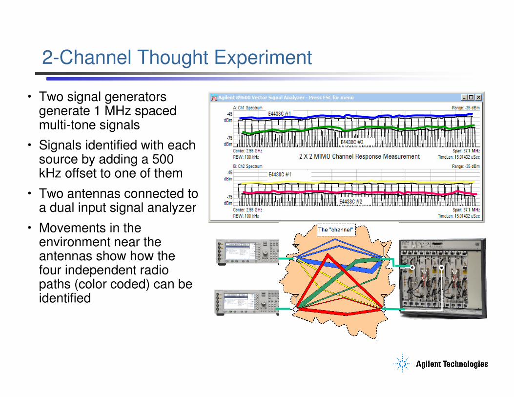
Aerospace and Defense Symposium 20072-Channel Thought Experiment
• Two signal generators generate 1 MHz spaced multi-tone signals
• Signals identified with each source by adding a 500 kHz offset to one of them
• Two antennas connected to a dual input signal analyzer
• Movements in the environment near the antennas show how the four independent radio paths (color coded) can be identified
Page 12
Beyond S-Parameters
© Agilent Technologies, Inc. 2007Page M6- 12
Aerospace and Defense Symposium 2007MIMO/STC Signal Creation
DataStream
XX MB/sec
IFFT
IFFT
TX0
TX1
En-coder
......
YY MB/sec
YY MB/sec
Bits
(1,0,1,1…)
Constellation
Points
(a+jb, c+jd…)
OFDM
Symbols
(waveform)
Page 13
Beyond S-Parameters
© Agilent Technologies, Inc. 2007Page M6- 13
Aerospace and Defense Symposium 2007Variations on the Theme
DataStream
2X MB/sec
IFFT
IFFT
TX0
TX1
StreamParser
X MB/sec
X MB/sec
• STBC (Alamouti) encoder creates 2 different
versions of the same bitstream, for robustness.
• Example: WiMAX Matrix A
• Note: numerous STBC schemes exist, and can be
used along with any of the below techniques.
• Vertical encoding splits the original bitstream
into two half-rate bitstreams, for throughput.
• Example: WiMAX Matrix B
• Example: 802.11n Direct Map modes
• Horizontal encoding accepts 2 bitstreams and
keeps them as separate TX chains, typically for
separate users.
• Example: WiMAX Matrix B
DataStream
IFFT
IFFT
TX0
TX1
STBCEn-
coderX MB/sec
X MB/sec
X MB/sec
DataStreamX MB/sec
IFFT
IFFT
TX0
TX1
X MB/sec
Y MB/sec
DataStreamY MB/sec
En-coder
DataStream(s)
X MB/sec
IFFT
IFFT
TX0
TX1
X MB/sec
X MB/sec
En-code
SS
• Spatial Spreading encoding accepts 2 encoded
bitstreams, and spreads them onto 2 TX chains,
(e.g. a+b, a-b) for improved diversity.
• Example: 802.11n Spatial Spreading modes
Page 14
Beyond S-Parameters
© Agilent Technologies, Inc. 2007Page M6- 14
Aerospace and Defense Symposium 2007MIMO/STC – Data & Spatial Streams, Channels
DataStream(s)
IFFT
IFFT
TX0
TX1
Bits
(1,0,1,1…)
Constellation
Points
(a+jb, c+jd…)
OFDM
Symbols
(waveform)
En-coder
SS
Spatial Streams
(aka Layers)
relate to the
original data
payload.
TX Chains
(aka Antennas)
relate to the
actual transmitted
signals.
Ant0
Ant1
Ant0
Ant1
RX0
RX1
Matrix
De-
coder
H00
H01
H10
H11
Channel Matrix
Individual freq response
curves for each TX-RX path.
Spatial
Stream(s)
OFDM
De-
mod
Data
Stream(s)
Page 15
Beyond S-Parameters
© Agilent Technologies, Inc. 2007Page M6- 15
Aerospace and Defense Symposium 2007WiMAX STC/MIMO Signals at the PHY Layer
. . .
. . .
Symbol n Symbol n+2Symbol n+1
TX 0
TX 1
Data subcarriers overlap, pilots don’t... data subcarrier
pilot subcarrier
Observing a single pilot frequency over time….TX1 TX1 TX1 TX1 TX1 TX1
TX0 TX0 TX0 TX0 TX0 TX0
Observing a single data subcarrier over time….TX1 TX1 TX1 TX1 TX1 TX1 TX1 …
+TX0 +TX0 +TX0 +TX0 +TX0 +TX0 +TX0
Matrix A = 2 versions of same dataMatrix B = 2 different data streams
CSM = 2 different handsets
Page 16
Beyond S-Parameters
© Agilent Technologies, Inc. 2007Page M6- 16
Aerospace and Defense Symposium 2007WiMAX STC/MIMO Signals at the PHY Layer
. . .
. . .
Symbol n Symbol n+2Symbol n+1
TX 0
TX 1
Data subcarriers overlap, pilots don’t...data subcarrier
pilot subcarrier
Constellation as transmitted...
Data subcarriers add,create a “constellationof constellations”.
...as received.
Pilots never overlap
Pilots
TX 0 or TX 1 TX 0 plus TX 1 crosstalk
Data
Page 17
Beyond S-Parameters
© Agilent Technologies, Inc. 2007Page M6- 17
Aerospace and Defense Symposium 2007MIMO--WiMAX vs. IEEE802.11n
• Preamble used for channel
estimation only
• Preamble on Tx0 only
• Many pilots, used for
demodulation reference and
MIMO matrix calculation
• Pilots move, not on every
symbol in a slot
• “Direct mapped” MIMO, no
spatial spreading (yet)
• Preamble used for channel
estimation, MIMO matrix
calculation
• Preamble on Tx0 and Tx1
• Few pilots, used for
demodulation reference only
• Pilots static, present for every
symbol
• “Direct mapped” and spatially
spread modes (a+b, a-b, etc.)
WiMAX 802.11n
Page 18
Beyond S-Parameters
© Agilent Technologies, Inc. 2007Page M6- 18
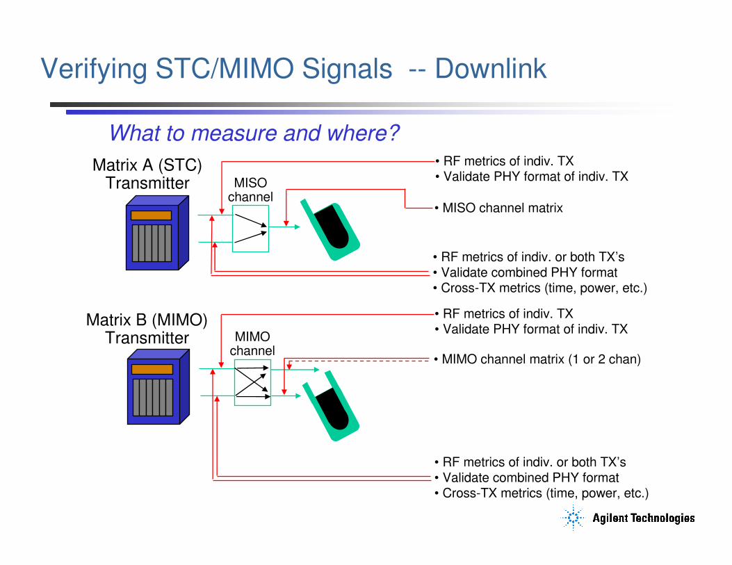
Aerospace and Defense Symposium 2007Verifying STC/MIMO Signals -- Downlink
Matrix B (MIMO)Transmitter MIMO
channel
• RF metrics of indiv. or both TX’s• Validate combined PHY format• Cross-TX metrics (time, power, etc.)
• RF metrics of indiv. TX• Validate PHY format of indiv. TX
• MIMO channel matrix (1 or 2 chan)
Matrix A (STC)Transmitter MISO
channel
• RF metrics of indiv. TX• Validate PHY format of indiv. TX
• RF metrics of indiv. or both TX’s• Validate combined PHY format• Cross-TX metrics (time, power, etc.)
• MISO channel matrix
What to measure and where?
Page 19
Beyond S-Parameters
© Agilent Technologies, Inc. 2007Page M6- 19
Aerospace and Defense Symposium 2007VSA for STC/MIMO
Input Chan. 0RX0
RX1Input Chan. 1
Matrix
Decoder
OFDM
Demod
TX0 + TX1 signal
(+ chan. response)
Chan
Estim.TX0 + TX1 signal
(+ chan. response)
Input Channel 1
Input Channel 2
Matrix A Analysis Stream
Matrix B Stream 1
Matrix B Stream 2
� Use Matrix Decoder
� Use Matrix Decoder
pilot-based EQ(decoder ON)
Preamble/pilot/data – based EQ (decoder OFF) OFDM Measurement Results MIMO Ch Freq Resp. (pilots only)
Eq Chan Freq Resp.
Conceptual Model
Page 20
Beyond S-Parameters
© Agilent Technologies, Inc. 2007Page M6- 20
Aerospace and Defense Symposium 2007Using Simulations & VSA to Understand Measurement Results, Interactions, Trade-offs
WiMAX MIMO Simulation Case Study
Page 21
Beyond S-Parameters
© Agilent Technologies, Inc. 2007Page M6- 21
Aerospace and Defense Symposium 2007Simulation Examples to Measure
• Transmitter0 Transmitter1 Crosstalk
– “Good” 41 dB
– “Not so good” 35 dB
– “Not good enough” 29 dB
• Transmitter Frequency Response Defect
– 2 MHz bandpass filter
• Simulation Output Stream Fed to 89600 VSA “Instance”
Operating Inside Simulation
– Same measurements, user interface as when connected to hardware
– Insert VSA at nearly any point; verify simulation is doing what is intended
Page 22
Beyond S-Parameters
© Agilent Technologies, Inc. 2007Page M6- 22
Aerospace and Defense Symposium 2007Modeling Crosstalk In ADS
Page 23
Beyond S-Parameters
© Agilent Technologies, Inc. 2007Page M6- 23
Aerospace and Defense Symposium 2007Crosstalk Results -- 41 dB
89600 VSA
Page 24
Beyond S-Parameters
© Agilent Technologies, Inc. 2007Page M6- 24
Aerospace and Defense Symposium 2007Crosstalk Results -- 35 dB
Page 25
Beyond S-Parameters
© Agilent Technologies, Inc. 2007Page M6- 25
Aerospace and Defense Symposium 2007Crosstalk Results -- 29 dB
Page 26
Beyond S-Parameters
© Agilent Technologies, Inc. 2007Page M6- 26
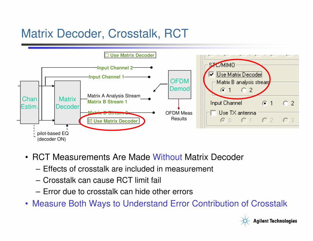
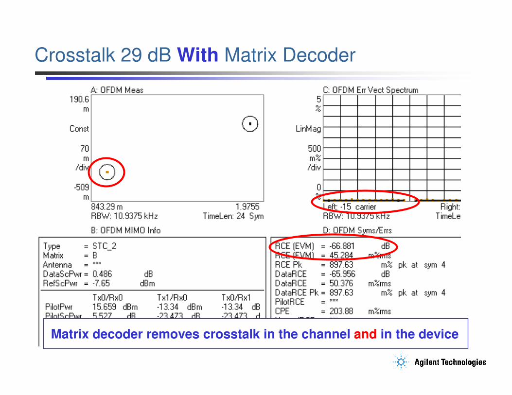
Aerospace and Defense Symposium 2007Matrix Decoder, Crosstalk, RCT
• RCT Measurements Are Made Without Matrix Decoder
– Effects of crosstalk are included in measurement
– Crosstalk can cause RCT limit fail
– Error due to crosstalk can hide other errors
• Measure Both Ways to Understand Error Contribution of Crosstalk
Matrix
Decoder
OFDM
Demod
Chan
Estim.
Input Channel 1
Input Channel 2
Matrix A Analysis Stream
Matrix B Stream 1
Matrix B Stream 2
� Use Matrix Decoder
� Use Matrix Decoder
pilot-based EQ(decoder ON)
OFDM Meas Results
Page 27
Beyond S-Parameters
© Agilent Technologies, Inc. 2007Page M6- 27
Aerospace and Defense Symposium 2007Crosstalk 29 dB With Matrix Decoder
Matrix decoder removes crosstalk in the channel and in the device
Page 28
Beyond S-Parameters
© Agilent Technologies, Inc. 2007Page M6- 28
Aerospace and Defense Symposium 2007Crosstalk Obscures Another Impairment
Measurement Without Matrix Decoder
Page 29
Beyond S-Parameters
© Agilent Technologies, Inc. 2007Page M6- 29
Aerospace and Defense Symposium 2007Crosstalk Obscures Another Impairment
Measurement With Matrix Decoder
Characteristic V-shapederror vector spectrum
Page 30
Beyond S-Parameters
© Agilent Technologies, Inc. 2007Page M6- 30
Aerospace and Defense Symposium 2007Modeling Frequency Response Defect in ADS
• 2 MHz Bandpass Filter
• Centered on Channel
• Transmitter 1 Only
• Example for Illustration
Only
– Not realistic, but effects and measurement results are easier to understand
Page 31
Beyond S-Parameters
© Agilent Technologies, Inc. 2007Page M6- 31
Aerospace and Defense Symposium 2007Measurement Results Ch 1 Direct Connection
Low EVM
No crosstalk
Page 32
Beyond S-Parameters
© Agilent Technologies, Inc. 2007Page M6- 32
Aerospace and Defense Symposium 2007Measurement Results Ch 2 Direct Connection
EVM very high;Demod successfuldue to pilots
Note filter effectsin Ch2 spectrum
Page 33
Beyond S-Parameters
© Agilent Technologies, Inc. 2007Page M6- 33
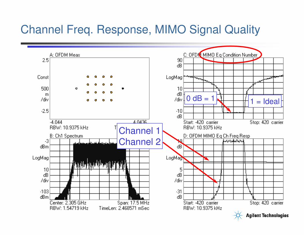
Aerospace and Defense Symposium 2007Channel Freq. Response, MIMO Signal Quality
Channel 1Channel 2
0 dB = 1 1 = Ideal
Page 34
Beyond S-Parameters
© Agilent Technologies, Inc. 2007Page M6- 34
Aerospace and Defense Symposium 2007MIMO “Condition Number”A Quantitative Measure of MIMO Quality
• Not a Demodulation Operation
• Does Not Require Matrix Decoder
• Calculated from Equalizer Channel
Frequency Responses
– One condition number value for each
subcarrier; log or linear format
– Condition number is a standard measure
of how ill-conditioned a matrix is
• Ratio of Matrix Max Singular Value to the Min Singular Value
– Value is always real, and always greater than or equal to one.
– Larger values indicate a more ill-conditioned matrix
• If the condition number is larger than the SNR of the signal, it is
likely that MIMO separation of the multiple data streams will not
work correctly
0 dB = 1
Page 35
Beyond S-Parameters
© Agilent Technologies, Inc. 2007Page M6- 35
Aerospace and Defense Symposium 2007Wave 2 Signal Generation & Analysis Solutions
Page 36
Beyond S-Parameters
© Agilent Technologies, Inc. 2007Page M6- 36
Aerospace and Defense Symposium 2007Signal Generation Software and Hardware
N7615B Signal Studio for 802.16 WiMAX software
N5182A MXG, E4438C ESG, or E8267D PSG Signal Generators
DUT
WiMAX
waveform
LAN or GPIB
Analog or digital baseband or RF WiMAX signal
Page 37
Beyond S-Parameters
© Agilent Technologies, Inc. 2007Page M6- 37
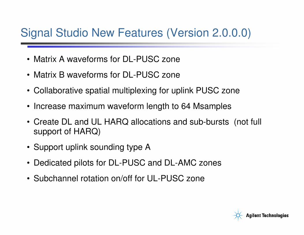
Aerospace and Defense Symposium 2007Signal Studio New Features (Version 2.0.0.0)
• Matrix A waveforms for DL-PUSC zone
• Matrix B waveforms for DL-PUSC zone
• Collaborative spatial multiplexing for uplink PUSC zone
• Increase maximum waveform length to 64 Msamples
• Create DL and UL HARQ allocations and sub-bursts (not full support of HARQ)
• Support uplink sounding type A
• Dedicated pilots for DL-PUSC and DL-AMC zones
• Subchannel rotation on/off for UL-PUSC zone
Page 38
Beyond S-Parameters
© Agilent Technologies, Inc. 2007Page M6- 38
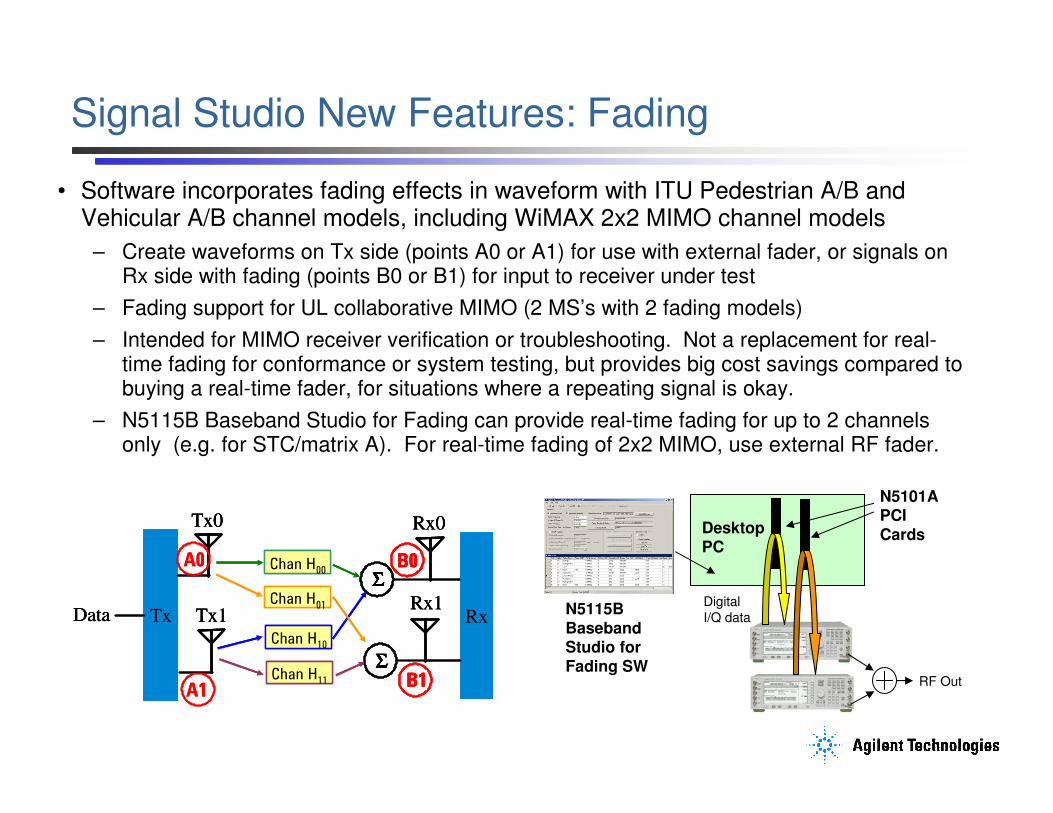
Aerospace and Defense Symposium 2007Signal Studio New Features: Fading
• Software incorporates fading effects in waveform with ITU Pedestrian A/B and Vehicular A/B channel models, including WiMAX 2x2 MIMO channel models
– Create waveforms on Tx side (points A0 or A1) for use with external fader, or signals on Rx side with fading (points B0 or B1) for input to receiver under test
– Fading support for UL collaborative MIMO (2 MS’s with 2 fading models)
– Intended for MIMO receiver verification or troubleshooting. Not a replacement for real-time fading for conformance or system testing, but provides big cost savings compared to buying a real-time fader, for situations where a repeating signal is okay.
– N5115B Baseband Studio for Fading can provide real-time fading for up to 2 channels only (e.g. for STC/matrix A). For real-time fading of 2x2 MIMO, use external RF fader.
Rx
Tx0
Tx Tx1Data
Chan H00
Chan H01
Chan H10
Chan H11
ΣΣΣΣ
ΣΣΣΣ
Rx0
Rx1
A0
B1A1
B0
Rx
Tx0
Tx Tx1Data
Tx0
Tx Tx1Data
Chan H00
Chan H01
Chan H10
Chan H11
ΣΣΣΣΣΣΣΣ
ΣΣΣΣΣΣΣΣ
Rx0Rx0
Rx1Rx1
A0
B1B1A1
B0B0
Desktop PC
N5101A PCI Cards
N5115B Baseband Studio for Fading SW
Digital
I/Q data
RF Out
Page 39
Beyond S-Parameters
© Agilent Technologies, Inc. 2007Page M6- 39
Aerospace and Defense Symposium 2007Baseband Synchronization
– For STC/MIMO, need to synchronize baseband generators to start waveform
playback simultaneously in both sources
– Signal Studio will automatically download waveforms, set up triggering, and initiate waveform playback in 2 ESGs, 2 PSGs, or 2 MXGs
– New in MXG version A.01.20 firmware: synchronize up to 16 MXGs with
baseband trigger repeatability < 1 ns and fine delay adjustment
10 MHz OUT
10 MHz IN
PATT TRIG IN
EVENT 2
PATT TRIG IN
E4438C ESGs or
E8267D PSGsRF Output
10MHz OutEVENT 1
RF Output
10MHz OutREF IN
EVENT 1
PATT TRIG
Master
MXG
Slave
MXG(s)
RF Output
10MHz Out
REF IN
EVENT 1
PATT TRIG
1
2
Normal Arb trigger
Etc.
Page 40
Beyond S-Parameters
© Agilent Technologies, Inc. 2007Page M6- 40
Aerospace and Defense Symposium 2007Add Impairments to Signals
• Use I/Q adjustments menu in signal generators to add impairments such as I/Q skew, quadrature angle, gain imbalance, etc.
• Add real-time noise with option 403 (calibrated AWGN)
• New in MXG A.01.20 firmware: option for adding phase noise impairment (N5182A-432)
Page 41
Beyond S-Parameters
© Agilent Technologies, Inc. 2007Page M6- 41
Aerospace and Defense Symposium 2007Measurement Configurations--Analysis
Page 42
Beyond S-Parameters
© Agilent Technologies, Inc. 2007Page M6- 42
Aerospace and Defense Symposium 2007Signal Analysis Hardware, Software
89601A VSA
Software
PSA Spectrum Analyzer X Series Signal Analyzers
89640 VXI VSA
(802.16 OFDMA Application for MXA)
Logic Analyzers
Oscilloscopes
ADS Simulation Software
Page 43
Beyond S-Parameters
© Agilent Technologies, Inc. 2007Page M6- 43
Aerospace and Defense Symposium 2007VSA STC/MIMO - Conceptual Model
Input Chan. 0RX0
RX1
Signals after separationinto TX1 and TX2
Input Chan. 1
Signals as-received;
any cross-talk or channel
combining looks like
added noise.
Matrix
Decoder
OFDM
Demod
TX1 + TX2 signal
(+ chan. response)
Chan
Estim.TX1 + TX2 signal
(+ chan. response)
Displays
� Use Matrix Decoder
� Use Matrix Decoder
demod metrics
Page 44
Beyond S-Parameters
© Agilent Technologies, Inc. 2007Page M6- 44
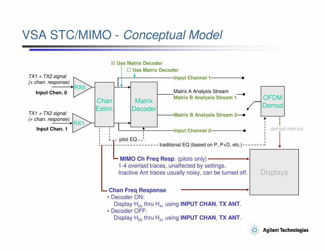
Aerospace and Defense Symposium 2007VSA STC/MIMO - Conceptual Model
Input Chan. 0RX0
RX1Input Chan. 1
Matrix
Decoder
OFDM
Demod
TX1 + TX2 signal
(+ chan. response)
Chan
Estim.TX1 + TX2 signal
(+ chan. response)
Displays
Input Channel 1
Input Channel 2
Matrix A Analysis Stream
Matrix B Analysis Stream 1
Matrix B Analysis Stream 2
� Use Matrix Decoder
� Use Matrix Decoder
pilot EQ traditional EQ (based on P, P+D, etc.)
demod metrics
MIMO Ch Freq Resp. (pilots only)1-4 overlaid traces, unaffected by settings. Inactive Ant traces usually noisy, can be turned off.
Chan Freq Response• Decoder ON:
Display H00 thru H41 using INPUT CHAN, TX ANT. • Decoder OFF:
Display H00 thru H41 using INPUT CHAN, TX ANT.
Page 45
Beyond S-Parameters
© Agilent Technologies, Inc. 2007Page M6- 45
Aerospace and Defense Symposium 2007Verifying STC/MIMO DL SignalsVSA Measurements What & Where?
Matrix A (STC)Transmitter
Matrix B (MIMO)Transmitter MIMO
channel
MISOchannel
• RF metrics of indiv. TX (ant 0 only)• Validate PHY format of indiv. TX (ant 0 only)
• RF metrics of indiv. or both TX’s• Validate combined PHY format• Cross-TX metrics (time, power, etc.)
• MISO channel responses• RF metrics of indiv. TX – pilot-based (ant 0 or 1)
• RF metrics of indiv. or both TX’s• Validate combined PHY format• Cross-TX metrics (time, power, etc.)
• RF metrics of indiv. TX (ant 0 only)• Validate PHY format of indiv. TX (ant 0 only)
• MIMO channel responses (1 or 2 chan)• RF metrics of indiv. TX – pilot-based (ant 0 or 1)
Page 46
Beyond S-Parameters
© Agilent Technologies, Inc. 2007Page M6- 46
Aerospace and Defense Symposium 2007Verifying STC/MIMO Signals – Single Channel
Matrix A (STC)Transmitter
Matrix B (MIMO)Transmitter MIMO
channel
MISOchannel1
1
1
1
1-Ch. VSA
Test Configurations Analyzer Configurations
1 Use when: signals are well-isolated- e.g. hardwired to individual TX’s.- e.g. before MISO/MIMO channels.
To get:- individual TX metrics (EVM, power, flatness)- cross-chan. metrics (pilot-based)- RCT pass/fail tests (crosstalk-limited) - PHY format validation
1a
1a Use when: Matrix A signals in MISO channel.
To get:- composite TX metrics (EVM, power, flatness)- individual TX metrics (pilot-based)- PHY format validation- channel profile validation- STC payload stream recovery
Page 47
Beyond S-Parameters
© Agilent Technologies, Inc. 2007Page M6- 47
Aerospace and Defense Symposium 2007Verifying STC/MIMO Signals – Multi-Channel
Matrix A (STC)Transmitter
Matrix B (MIMO)Transmitter MIMO
channel
MISOchannel
2-Ch. VSA
Test Configurations Analyzer Configurations
Use when: signals are not well-isolated- e.g. crosstalk-limited is not good enough- e.g. downstream of MIMO channel
To get:- individual TX metrics (simultaneous)- composite TX metrics (simultaneous)- cross-chan. metrics (gain, phase, skew,
correlation, coherence, etc.)- channel matrix meas. (Hxx, matrix cond.)- beam-forming validation - channel fading validation- PHY format validation- MIMO payload stream recovery
2
2
2 2
Page 48
Beyond S-Parameters
© Agilent Technologies, Inc. 2007Page M6- 48
Aerospace and Defense Symposium 2007Verifying STC/MIMO Signals – Combined 1-Chan.
Matrix A (STC)Transmitter
Matrix B (MIMO)Transmitter MIMO
channel
MISOchannel
1-Ch. VSA + Combiner
Test Configurations Analyzer Configurations
Use when: economy is a concern- e.g. when pilot-based meas. are sufficient
To get:- individual TX metrics (pilot-based)- composite TX metrics (pilot-based)- cross-chan. metrics (limited)- PHY format validation
3
3
3 3
3
Page 49
Beyond S-Parameters
© Agilent Technologies, Inc. 2007Page M6- 49
Aerospace and Defense Symposium 2007
OFDM Frame Summary
OFDM Frame Summary from VSA
Preamble Power as RSSI,Preamble RCE, and Preamble PCINR R1 and R3
Statistic result summary:Mean, Peak Hold, & StdDev
RMS averaging = 10
Page 50
Beyond S-Parameters
© Agilent Technologies, Inc. 2007Page M6- 50
Aerospace and Defense Symposium 2007New VSA MIMO Measurements & Displays
• OFDM MIMO Info Trace
– DataScPwr – reports the power of the data subcarriers, referenced to RefScPwr
– RefScPwr – reports the power of the reference subcarriers
– PilotPwr – reports the power in the pilot pattern for the selected antenna
– PilotScPwr – reports the relative per-pilot subcarrier power, referenced to RefScPwr
– PilotRCE – reports the RCE of the pilot pattern for the selected antenna
• Condition number
• MIMO Equalizer Channel Frequency Response
Page 51
Beyond S-Parameters
© Agilent Technologies, Inc. 2007Page M6- 51
Aerospace and Defense Symposium 2007Protocol Test - E6651A Mobile WiMAX Test Set
• Base Station Emulation
• IP Traffic Support
• Network Entry
• RF Parameter measurements
• Wave 2 Support
– DL
– STC
– SM
– UL collaborative MIMO
• Measure UL Signals Without External Equipment
Page 52
Beyond S-Parameters
© Agilent Technologies, Inc. 2007Page M6- 52
Aerospace and Defense Symposium 2007Manufacturing TestN8300A Wireless Networking Test Set
• RF Parametric Test Set
• One Box Integrated Solution
– Source
– Receiver
• Standard-Compliant PHY Testing
• SCPI Interface
• Vector Signal Generation, Analysis
Page 53
Beyond S-Parameters
© Agilent Technologies, Inc. 2007Page M6- 53
Aerospace and Defense Symposium 2007Agilent WiMAX Solutions
Page 54
Beyond S-Parameters
© Agilent Technologies, Inc. 2007Page M6- 54
Aerospace and Defense Symposium 2007Learn by Making Measurements
• 89601A VSA Software, Free Demo License,
N7615B Signal Studio, Free Simulation Mode
– Recorded signals provided: perform any kind of vector analysis or demodulation
– Simulated hardware
– Tutorials
– Troubleshooting help
– Example displays
• VSA & Signal Studio Software
14-day free trial licenses
– Connect to hardware
– Generate & downloadsignals
Page 55
Beyond S-Parameters
© Agilent Technologies, Inc. 2007Page M6- 55
Aerospace and Defense Symposium 2007Resources
– Agilent WiMAX Portal: www.agilent.com/find/wimax
www.agilent.com/find/webcasts
– Agilent ADS: http://eesof.tm.agilent.com
– Application Notes:
• 89600 Series VSA Software for OFDMA Evaluation and Troubleshooting,
Self-Guided Demonstration, Literature No. 5989-2383EN
• “IEEE 802.16e WiMAX OFDMA Signal Measurements and
Troubleshooting” AN-1578 Literature No. 5989-2382EN
• Many others (fixed & mobile WiMAX, OFDM) - See portals
– Webcast / eSeminar (recorded): “Testing Mobile WiMAX Radios from Pre-Certification through Manufacturing” www.techonline.com
– RF Design magazine article on OFDM Troubleshooting by Bob Cutler: http://rfdesign.com/mag/radio_effects_physical_layer/
– Trial Versions 89601A VSA Software & N7615B Signal Studio for 802.16 WiMAX (Download or contact Agilent)