WIND GENERATORS HISTORY © M. Ragheb
4/30/2019
“Of all the forces of nature, I should think the wind contains the largest amount of motive power … Take any given
space of the Earth’s surface, for instance, Illinois, and all the power exerted by all the men, beasts, running water and
steam over and upon it shall not equal the 100th part of what is exerted by the blowing of the wind over and upon the
same place. And yet it has not, so far in the world’s history, become properly valued as motive power. It is applied
extensively and advantageously to sail vessels in navigation. Add to this a few windmills and pumps and you have
about all. As yet the wind is an untamed, unharnessed force, and quite possibly one of the greatest discoveries hereafter
to be made will be the taming and harnessing of it.”
President Abraham Lincoln, “Discoveries and Inventions” 1860 lecture, New York Times, November 22,
1936.
INTRODUCTION
Wind power has been used since early history by mariners for sailing boats on
rivers and lakes and then ships at sea (Fig. 1). Since the early recorded history it has been
used by numerous cultures and civilizations. It is a fascinating field of study and
endeavor attracting people from all backgrounds and walks of life. It captivates the
interest of passionate creative and romantic people. Its future success will depend on
setting its footing on solid and realistic science and engineering and away from
unrealistic dreams of perpetual motion machines and unbridled romanticism.
Figure 1. Sail-ships used the wind as a motive power for commerce and war.
Windmills and water driven mills were the only power generators for over 1,200
years predating the 18th century Industrial Revolution. They existed in antiquity in
Egypt, Persia, Mesopotamia and China. In the 7th century BC, king Hammurabi of
Babylonia implemented a plan to irrigate the fertile plains of the Euphrates and Tigris
Rivers using vertical axis machines. In the 3rd century BC, Hero of Alexandria, Egypt
built a 4 blades horizontal axis machine to power a musical organ with compressed air.
Figure 2. Early 5,000 year old ancient Egyptian sailboats depictions.
Wind energy conversion has been reinvented many times in human history and is
undergoing a new process of reengineering as the leading mechanically based renewable
energy form. It is challenging the conventional energy sources into becoming a viable
alternative to them in the future.
The word windmill refers to a wind powered machine that grinds or mills grain
such as wheat or corn and turns it into flour for bread-making. This has been the most
common function in addition to numerous other applications such as: grinding of spices,
lumber sawing, mines ventilation, iron and copper foundries power, gun powder
manufacturing, oil extraction from oil seeds, nuts and grains, converting old rags into
paper, grinding colored powders into dyes, manufacturing snuff tobacco and water
pumping in Europe in the pre-Industrial Revolution era, and even dispatching bee hives
into besieged towns in warfare.
Holland used windmills since 1350 AD to drain marshes and shallow lakes and
turning them into productive agricultural land. They were coupled to an Archimedean
screw, Egyptian noria or Persian water wheel; all of them early pump concepts which
could elevate water to a height of 5 meters.
The noria’s etymology comes from the Arabic: “Al Naoura” which literally
means: “The wailing;” so called because of the wailing sound it generates as it rotates.
The “noria,” is basically a water wheel that lifts water into an aqueduct carrying water to
cities and fields using the flow energy of a water stream, similar to the modern hydraulic
ram. It has a function similar to the chain pumps of which the “saqiya,” literally
“irrigator” in Arabic, which dates back to Babylonian (700 BC) and Pharaonic (200 BC)
times, is an example. Noria machines were in widespread use in the medieval Islamic
culture before their introduction into the European wind mills, and specimens are still in
operation in some parts of the world today. Their introduction may have originated from
Spain where Ibn Bassal (1038-1075 AH) of Al Andalus (Andalusia) pioneered the use of
a flywheel mechanism in the noria and sakiya to smooth out the delivery of power from
the driving device to the driven machine.
Wind turbines were replaced by steam and internal combustion engines using
fossil fuels ranging from coal to oil and natural gas as well as nuclear energy. Nowadays
wind machines are primarily used in electrical power generation. So that the
terminology: “wind generators” becomes a more appropriate designation.
Wind power has evolved from impulse or drag driven heavy systems to the use of
light aerodynamic systems. The latter is not a modern concept: It has been known to the
ancient sailors and mariners and was applied to the development of sail wind mills.
WIND MACHINES IN ANTIQUITY
Out of respect of the wind capability of destructiveness in tornadoes, hurricanes,
typhoons and storms, legends arose that the winds were imprisoned underground and
were released at the whim of a beneficent or malevolent deity. In ancient Greece, the god
Aeolus was the ruler of the winds.
Many primitive people thought that the wind could be controlled by magic.
Power over the wind was ascribed to the Royals in some societies, and later to the clergy.
In early Christianity, it was thought that the wind was God breathing to punish or
reward the Earthly mortals. Mariners for centuries had legends dealing with their fears
and superstitions about the wind.
As early as 4000 BC, ancient Egyptian pottery depicts ships with square sails
using the prevailing north wind to sail up the Nile River from north to south against its
current (Fig. 2). During the ancient Egyptian Fifth Dynasty around 2500 BC, sailing
ships advanced enough to go to sea and made trading trips around the horn of Africa to
the land of Punt. A relief on the walls of the Deir Al Bahari Queen Hatshepsut’s temple
in Luxor, Egypt, shows the sailboats sent on a trading and exploration expedition around
the East coast of Africa (Fig. 3). They sailed through an ancient canal dug to connect the
Nile River to the Red Sea.
Figure 3. Relief of single and double mast sailboats on the walls of the Deir Al Bahari
Queen Hatshepsut’s temple in Luxor, Egypt, commemorating a trading expedition to the
land of Punt.
By 150 BC an account by Hero of Alexandria in his Spiritalia describes a
pneumatic application of a 4-bladed wheel driven by the wind moving the piston of an air
pump to blow the pipes of a musical organ. A prayer wheel was used in Asia around 400
AD whose scoops caught the wind and rotated on a vertical shaft.
ISLAMIC CULTURE WINDMILLS
Around 200-100 BC windmills with woven reed sails were used in the Middle
Eastern region for grinding grain. The first documented invention of a real wind mill
occurred in the year 644 AD during the rule of the second Islamic Khaliph: Omar Ibn Al
Khattab. A subject of Persian heritage, who proposed to him that he is able to build one,
was commissioned by the Khaliph Omar to build a grain mill rotated by the wind.
The next written account comes from two Islamic geographers. It tells of wind
mills built in the sandy and windy province of Seistan in present day Iran around 947
AD. The first application had to do with drifting sand dunes which could bury whole
villages and cities. To control the sand drifts, the people of Seistan ingenuously enclosed
the drift or dune in a structure of timber and thorny bushes higher than the dune. In the
lower part they opened a door for the wind to enter and blow away the upper levels of
sand in a whirlwind or tornado carrying the sand to be deposited evenly on the
surrounding fields.
The Islamic geographer Ali Al Massoudi writes about Seistan in 947 AD that:
“Wind turns mills which pump water from wells to irrigate the gardens. There is no
place on Earth where people make more use of the wind.”
Another Islamic scholar, Al Qazwini in 1283, describes how the people of Seistan
used the wind to grind their wheat, as well as to control the drifting sand and to pump
water. From that perspective, Seistan can be considered as the birth-place of the Eastern
vertical wind mill in Islamic times.
Figure 4. Exterior vestiges of ancient vertical-axis windmills or “Panemones” at Seistan,
near the border between Iran and Afghanistan.
Figure 5. Interior detail of vertical Panemone wind mills at Seistan, Iran. The rotors were
made from fabric or bundles of reeds and wood.
The Syrian cosmographer Al Damashqi (The Damascan) in 1300 AD describes in
detail such horizontal mills. They were erected in high places on top of hills, a minaret or
tower in a castle. They were built as two stories structures. The mill that turned and
ground was in the upper story. The lower part contained the mill that was rotated by the
blowing wind. The wheel turned one of two millstones in the upper section. Four slits
existed in the walls of the first story with the outer part wider than the inner part. This
formed ducts through which the wind blew from any direction. The ducted wind hit a
reel with 6-12 fabric-covered arms rotating it. The reel moved the millstone that ground
the wheat.
Other vertical wind mills were used around the same time period in Afghanistan.
They were driven by the north wind prevalent there. A series of shutters controlled the
wind inlet.
Used originally in Persia and Afghanistan, windmills spread throughout the
Islamic world and the Far East grinding grain and pumping water. They were adapted to
crushing sugar cane for the manufacture of molasses and the extraction of sugar in Egypt.
Centuries later, in the West Indies and the Caribbean, the West Indians hired Egyptian
millwrights to establish the first sugar plantations there.
As Genghis Khan invaded Persia in the 12th century, the millwrights were induced
back to China where bamboo horizontal mills with sails of matting adapted from Chinese
sailing boats designs became common in the open fields. Superstition apparently
suppresses their use today.
MEDIEVAL EUROPE WINDMILLS
The concept of the windmill first spread to Europe through the Islamic culture
established in Morocco, at that time-period Andalusia or Portugal and Spain, by traders
and merchants. Another route was through the trade routes through Russia and
Scandinavia. A third way is attributed to the returning crusaders to Europe from the
Middle East. A fourth way was through then Islamic Sicily into Italy.
The scholar Mabillon in 1105 AD writes that a convent in France was allowed to
construct watermills and windmills. Windmills according to him were becoming
common in Italy in the 12th century. Questions aroused about whether the tithes for them
belonged to the clergy. The controversy was decided in favor of the Church by Pope
Celestine III.
Mabillon recounts a story about an abbey in Northamptonshire, England in 1143
AD that was in a wooded area which was denuded over a period of 189 years: “That in
the whole neighborhood there was no house, wind or water mill built for which timber
was not taken from this wood.”
The first wind mill built in England was in Bury St. Edmunds in 1191. It was
built in defiance of the then vested authority and later destroyed by the Abbot. By the
14th century the British monarchs watched the victories and defeats of their battling
armies from the safety and high-ground of the top of windmills scattered on the hills.
A windmill was erected in Cologne, Germany in 1222 AD. A windmill appeared
in Siena Italy in 1237 AD. Count Floris V in Holland granted the burghers of Haarlem
the right to pay 6 shillings in tax for a windmill and 3 for a horse mill in 1274.
In the 12th to the 15th centuries the construction of windmills spread throughout
central Europe all the way to Scandinavia reaching Finland in 1400 AD. Windmills
became the prime power movers all over Europe for grinding grain, pumping water,
paper making, pressing oil from oil seeds, sawing wood, and even dispatching bee hives
into besieged towns during warfare.
The Dutch drainage mill was developed in Holland maintaining the land
reclaimed from the sea, marshes or shallow lakes. The Cistercian monks in France had
introduced such a type of windmill to drain the lakes of their region. Peat was being
mined for fuel needed by emerging cities, and this formed shallow lakes which grew in
size over time and required systematic drainage by the 1300s.
The first Dutch marsh mills were started by 1400. By 1600 there were 2,000 of
them operating to drain 2 million acres of land in Holland.
Figure 6. Los Molinos at Consuegra 48 miles south of Madrid on the plains of Castilla-La
Mancha, Spain.
Windmills were so common by the end of the 16th century that the author Miguel
de Cervantes had no doubt about the familiarity of his readers with windmills and the
encounter of his hero Don Quixote with them in La Mancha; which originally was an
Arabic word meaning “dry, waterless land.” The wind flour-mills were on the River
Ebro and Don Quixote took them for giants and charged them with his horse Rocinante
and his squire Sancho Panza.
AEGEAN AND MEDITERRANEAN WINDMILLS
The windmills of Crete, the Aegean Islands as well as Portugal and Spain were
tower mills. The post mill which evolved into the tower mill was never observed in the
Aegean area. Jib or triangular sails were typically used in the Iberian Peninsula and the
Mediterranean. Their similarity to sailing ships is noticeable. The Cretan windmills
were aerodynamically and structurally the inspiration to the modern racing yacht. They
flew 6-12 triangular fabric sails that were put up or down through roller reefing or by
rolling them around the sail support. They were situated at the center of the mill or
sheeted at midship.
Figure 7. Sail water pumping wind mills harvesting the wind in large numbers on the
island of Crete in the Mediterranean Sea.
The Aegean Islands mills were small compared with the European mills with a
size of 4-12 meters in diameter. The Dutch polder or scoop mill measured about 29
meters in diameter. They were situated as 4-12 in a row. Being efficient and well -suited
to the local conditions, they survived long after their use as wind power usage declined
elsewhere.
Polders are low lying tracts of land forming hydrological entities that are
surrounded by dikes or embankments. These are usually land reclaimed from a body of
water such as an ocean shore or a shallow lake. They exist usually below sea level at
river deltas, coastal areas and fenlands and require constant drainage by opening sluices
at low tide, by wind mills in the past and pumps at present. The city of New Orleans in
the USA can be considered to be a polder.
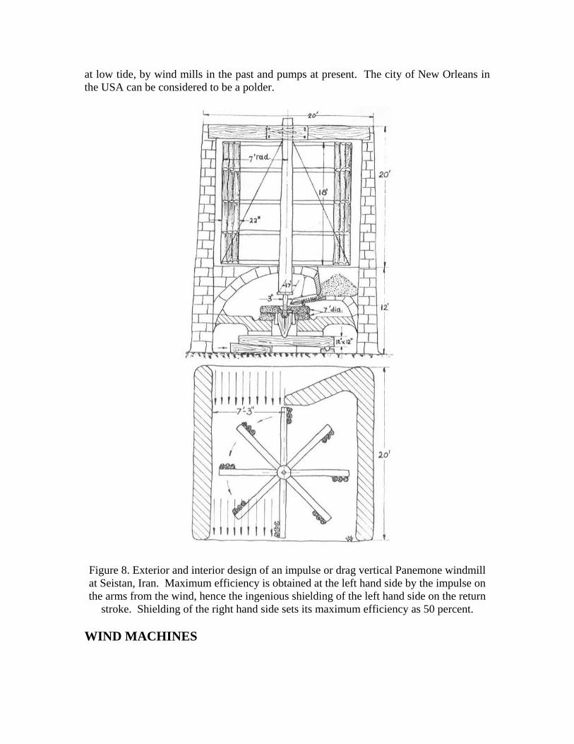
Figure 8. Exterior and interior design of an impulse or drag vertical Panemone windmill
at Seistan, Iran. Maximum efficiency is obtained at the left hand side by the impulse on
the arms from the wind, hence the ingenious shielding of the left hand side on the return
stroke. Shielding of the right hand side sets its maximum efficiency as 50 percent.
WIND MACHINES
Compared with modern machines powered by fossil fuels, wind machines depend
on the wind as a fuel. Unfortunately, it is intermittent, unreliable, unsteady, and
unpredictable. In some places on Earth it does not even blow at all, necessitating the use
of animal and human muscle as a source of power. Yet the advantage of the wind as a
source of energy is that it is not just renewable, but infinite in magnitude originating in
the sun’s energy that is trapped in the Earth’s atmosphere.
ANCIENT WIND MILLS
The earliest wing mill structures were developed in the Middle East at the time of
the Islamic Civilization and spread along the Mediterranean coast and in Persia around
500-900 AD. Some early wind mills vestiges still exist at the Seistan site in Iran Figs (5,
6, 8). These were vertical axis mills with their arms or sails revolving parallel to the
ground.
Wind mills technology was partly transferred to Medieval Europe by the returning
crusaders in the 12-th century. It developed there as the horizontal axis design with tall
structures on which the sails turned at a right angle to the ground.
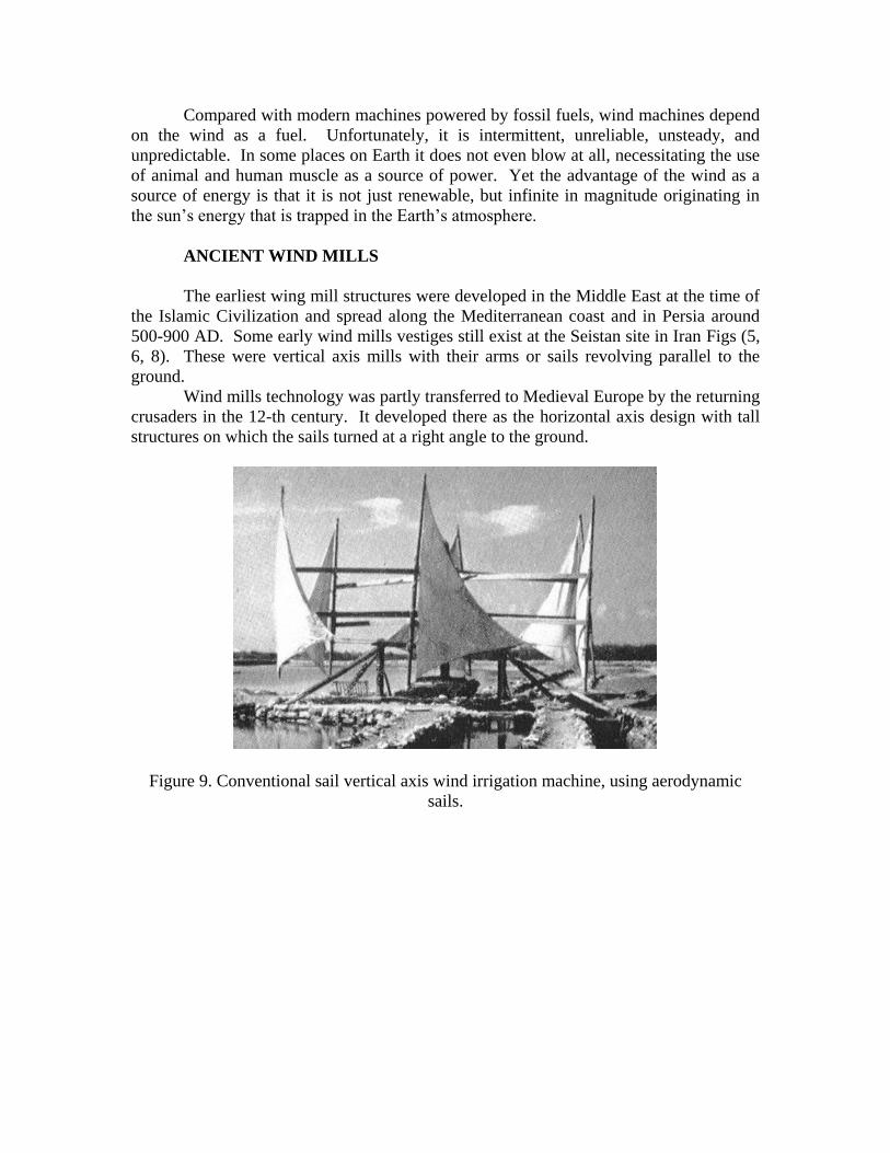
Figure 9. Conventional sail vertical axis wind irrigation machine, using aerodynamic
sails.
Figure 10. Chinese sail vertical axis wind irrigation machine using impulse or drag sails.
Vertical axis mills are still being built in different parts of the world by
enterprising farmers for irrigation and drainage purposes. A conventional aerodynamic
sail and a Chinese impulse sail vertical axis designs are shown in Figs. 9 and 10. An
early description of a Chinese wind mill was around 1219 AD by Yeh Lu Chu Tshai, a
Chinese statesperson.
A vertical axis windmill using drag or impulse rather than fabric sails in
Nebraska, USA around 1898 is shown in Fig. 10.
Figure 11. Merry go-round drag-sails water-pumping mill at Lincoln, Nebraska, USA,
circa 1898.
Vertical axis mills have the advantage of a simple design consisting of 6 or more
sails that are set upright upon horizontal arms resting on a tower or in the open, and
which are attached to a vertical shaft positioned at the center. The sails are set in a fixed
position that is oblique to the direction in which the wind will hit them. Thus, their
operation is independent of the direction from which the wind blows.
A disadvantage of the vertical axis design is that only one or two of the sails
would catch the wind at any given time. The part of the sail catching the wind must then
expend energy moving the dead weight of the part that is not catching it. Thus vertical
axis mills are considered as less efficient than horizontal axis wind mills where the force
of the blowing wind is evenly distributed on all sails.
EUROPEAN WIND MILLS
European wind mills were custom-designed and built with the particular site and
wind conditions taken into consideration, accordingly not two of them were exactly alike.
They were of primary importance in the life of rural Europe, grinding grain for flour and
pumping water, so that they were installed before other structures were erected in
European villages. Being erected on high ground to catch the wind from all directions,
they were major landmarks seen from long distances by travellers.
The drag type horizontal axis machines are known to possess a larger efficiency
than the vertical axis types; hence they were widely adopted in Europe. Villagers
personalized them giving them individual names. The miller doubling as a windwright
commanded high authority, wealth, power and respect in the village hierarchy. Being the
richest man in town made him more important than the appointed or elected officials.
On the other hand, the miller’s profession was a hazardous one especially under
high wind conditions. It required a great skill and bodily strength climbing up the
structure furling the sails to prevent the windmill arms from running away, damaging or
destroying the mill structure under wind gale conditions. With wooden mills, the danger
of fire was prominent through friction .
There existed three types of European wind mills:
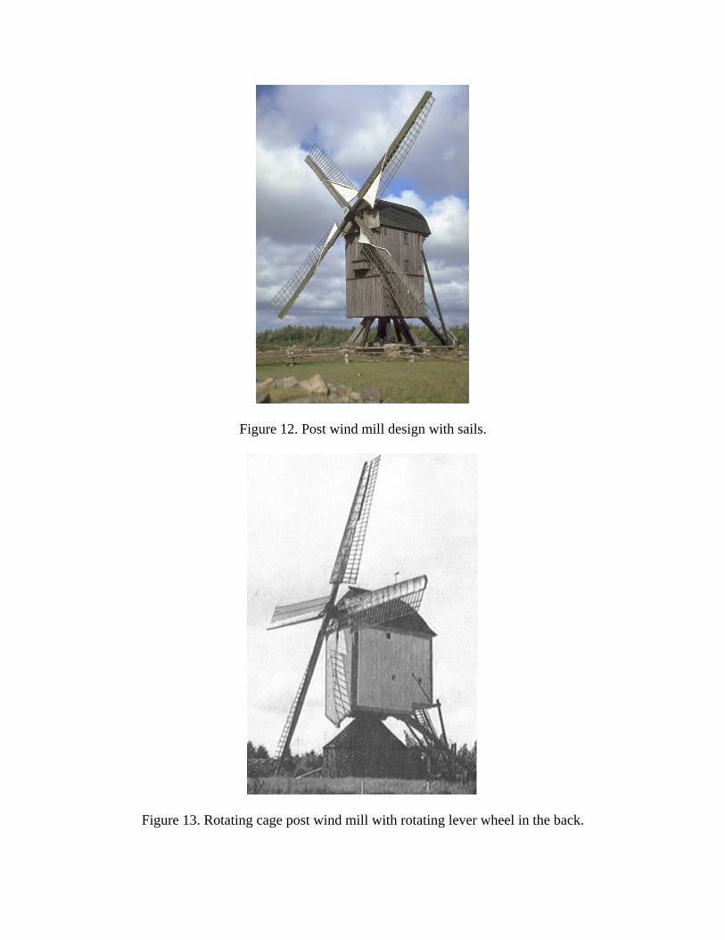
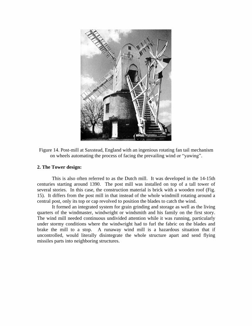
1. The Post design:
The Post design refers to a massive upright post around which the entire body of
the mill rotates in the direction of the blowing wind and was first described in 1270 AD.
The body of the mill supported the sails and the machinery. These earlier designs were
constructed out of wood. A rotating cage post design is shown in Figs. 12, 13, and a post
design with a tail fan is shown in Fig. 14.
They used wood cog and ring gears to transmit the blades rotation to a horizontal
grind stone. It was an adaptation of a horizontal axis water wheel attributed to Vitruvius
in antiquity.
Figure 12. Post wind mill design with sails.
Figure 13. Rotating cage post wind mill with rotating lever wheel in the back.
Figure 14. Post-mill at Saxstead, England with an ingenious rotating fan tail mechanism
on wheels automating the process of facing the prevailing wind or “yawing”.
2. The Tower design:
This is also often referred to as the Dutch mill. It was developed in the 14-15th
centuries starting around 1390. The post mill was installed on top of a tall tower of
several stories. In this case, the construction material is brick with a wooden roof (Fig.
15). It differs from the post mill in that instead of the whole windmill rotating around a
central post, only its top or cap revolved to position the blades to catch the wind.
It formed an integrated system for grain grinding and storage as well as the living
quarters of the windmaster, windwright or windsmith and his family on the first story.
The wind mill needed continuous undivided attention while it was running, particularly
under stormy conditions where the windwright had to furl the fabric on the blades and
brake the mill to a stop. A runaway wind mill is a hazardous situation that if
uncontrolled, would literally disintegrate the whole structure apart and send flying
missiles parts into neighboring structures.
Figure 15. Tower water pumping mill for drainage in Holland.
The post and the tower mills had to be oriented manually to face the wind using a
large wheeled lever at the back of the mill. A lateral fan was added later to automate the
yaw orientation of the mill into the prevailing wind direction.
3. The Smock design:
The smock design differs from the tower mill in the construction materials
chosen. The smock design has a stone base with a wooden upper section that is framed
with weather boarding that is either tarred or painted white. The name smock originates
from the way these mills appearance looks like the linen smocks worn at the time in
Holland and Europe (Fig. 16).
Figure 16. Rotating roof Dutch smock design for pumping drainage water. A pegged
wheel acted as a yaw mechanism to rotate the wind mill to face the wind.
THE AMERICAN WINDMILL
The slow multi-blade design appeared in Europe in the 17th century. Leupold
Jacob from Leipzig in 1724 in a book: “Journal of Hydraulic Arts,” or in German:
“Schauplatz der Wasser Künste,” introduced an 8 bladed self-regulating wind turbine that
drove a single action piston water pump using a crankshaft and a tie rod. In an ingenious
design, each blade was capable of pivoting around its own axis maintained by a spring
system that is progressively extended in a high wind condition resulting in the rotor
revolving in a gale no faster than in a moderate wind, avoiding the destructive situation of
a runaway turbine.
Figure 17. American water pumping wind mill with a ground water storage tank used for
cattle drinking.
Figure 18. American water pumping wind mill with a tower water storage tank. This is
an example of a gravity pumped energy storage system.
This multi bladed design did not spread on the European continent, but rather on
the American Great Plains. Starting in 1870, as a simple, economic and a very successful
design, it conquered the American continent and immigrated back to Europe and the rest
of the world where it was named: “The American Wind Mill.”
The most common windmill in America was built in the 19th century as a vertical
steel structure topped with a rotating multi bladed drag or impulse propeller that caught
the wind. Its rotational motion is converted into linear motion that pumped water and
stored it in a water tank for irrigation and cattle drinking (Figs. 17, 18).
The American Wind Mills were simple in construction and were well
standardized. They could be easily dismantled, moved to other locations where they
could be reassembled. Their maintenance was easy with parts that are interchangeable
and could be cannibalized from one machine for the benefit of another.
The standardization led to the spread of the American wind mills in many slightly
altered versions in the American West as well as all over the World. The intense
competition among American windmills versions at the World Columbian Exposition in
Chicago in 1893 is shown in Fig. 19, compared with the appearance of a single European
smock wind mill design.
Early on, wooden slats were nailed to rims with tail rudders for orientation
towards the wind or yawing. Instead of using a rudder, some designs used weather vanes
operating downwind from the tower. Speed control was provided by spring and weight
mechanisms and by feathering the blades to reduce the thrust in high winds. Around
1870, galvanized steel blades replaced the wooden slats allowing high speed operation
that needed a reduction gearing mechanism to operate the reciprocal water pumps at their
required low speed.
Figure 19. American Windmills versions competition at The World Columbian
Exposition, Chicago, USA in 1893, as a commemoration of Christopher Columbus
arrival to the New World 100 years earlier.
The Halladay design introduced in 1854 evolved into the Aermotor and Dempster
designs still operational in different parts of the world. Over the period 1850-1970 about
6 million small turbines of 1 Horse Power (HP) power or less were installed in the USA,
primarily for water pumping for cattle and farm needs. Larger wind mills with rotor
diameters of up to 18 m in diameter provided water for the steam boilers of the
locomotives of the western railroads. This is really how the American West was won:
through wind mills and the railroads.
HISTORICAL DEVELOPMENT
The earliest horizontal axis wind mills possessed short sails, which were made
later longer and more efficient in catching the energy from the wind. As the sails were
elongated, the axle or wind shaft on which they rotated had to be emplaced higher off the
ground on the wind mill structure or buck.
Irrespective of their design some common features exist in windmills. For
horizontal axis mills:
1. A means of catching the wind through sails, arms or blades rotating around an axle.
2. A mechanism to turn the sails, arms or blades so that they face the wind. Otherwise, as
the wind direction shifts, the wind mill would come to a halt. This is designated as a yaw
system.
3. A gear system and interlocking equipment transmitting the wind energy to the
millstone, water pump, timber saw, electrical generator or machinery that they are
powering.
Vertical axis mills share the first and third features only since their sails are
always facing the wind without the need to adjust them like in the case of the horizontal
axis mills.
The use of sails on the European wind mills added and element of aerodynamic
lift leading to higher rotor efficiency through its increased speed. The perfection process
took 500 years leading to mills that have the components and features of the modern
wind mills.
Some mills had aerodynamic brakes, spoilers, flaps and leading edge airfoil
sections and were precursors to the modern airplane wings. Features of modern airfoil
rotor blades were incorporated through insight and trial and error: a nonlinear twist of the
blades from their root to their tip, introducing a camber along the leading edge,
emplacement of the blade spar at the quarter chord position at 25 percent of the way from
the leading edge to the trailing edge, and designing the blade with its center of gravity at
that same ¼ chord position.
WIND MILL SAILS AND BLADES EVOLUTION
The simplest windmills sails are just cloth sails attached to the rotating arms or
blades. Designs using multiples sails were used in the Mediterranean region such as at
Alexandria, Egypt (Fig. 20). A design with small sails attached to multiple arms used in
Greece is shown in Fig. 21. With a small number of arms, large sails can be used as
shown for a Portuguese wind mill equipped will bells at the end of its rotating arms as
shown in Fig. 22. The bells generated an audible warning for stray cattle or humans.
Figure 20. Alexandria, Egypt’s Moulins du Gabari (Al Qabbari), built on a hill
overseeing the harbor of Alexandria, showing their furled sails.
Figure 21. Small sails and large number of arms windmill in Greece.
Figure 22. Large sails windmill with four arms with attached bells in Portugal. Hanging
bells warn humans and cattle about the rotating arms.
Better structural strength was achieved with wooden frames covered with fabric
in what became known as common sails. Initially the cloth was only placed over the
frames or entirely removed. Later, a method for reefing or furling the cloth was
developed to control the sail area depending on the wind speed. A common sail on a
French wind mill is shown in Fig. 23, and on a Spanish sail in Fig. 24.
Figure 23. French wind mill with tail pole and wooden sails covered with cloth.
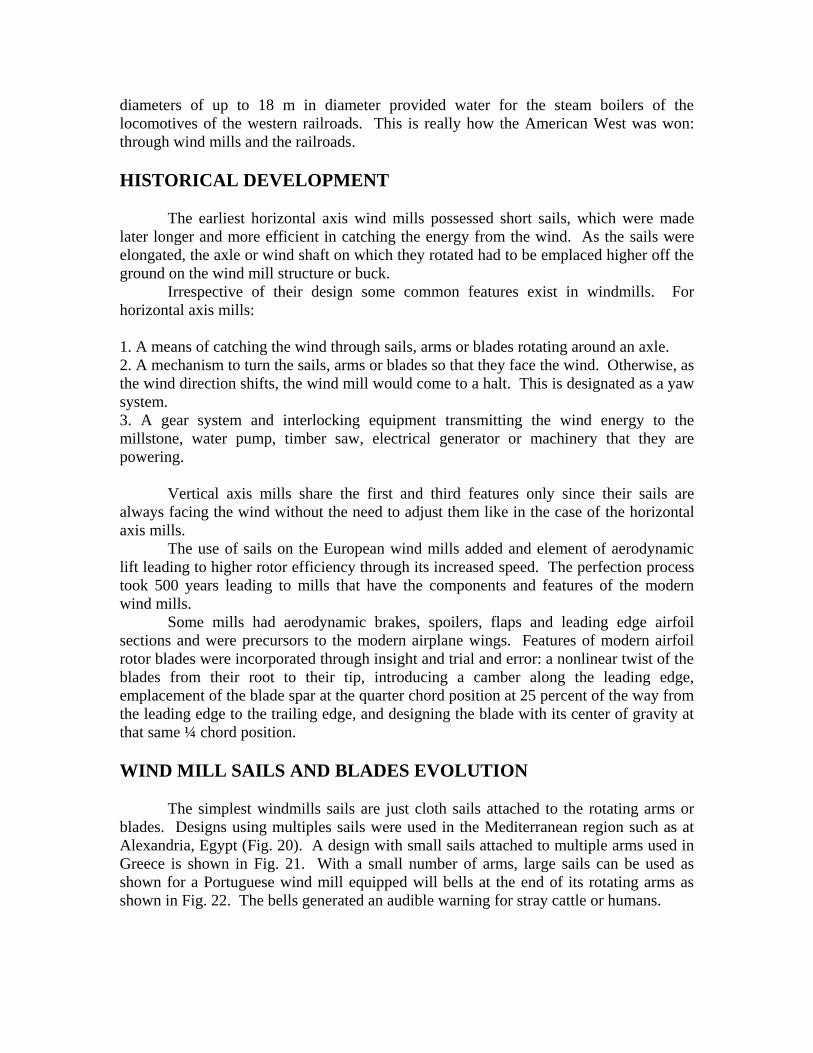
Figure 24. Cloth-covered wood sails wind mill in Spain.
The common sails were light in weight and powerful but they had to be stopped
for the mill master to furl the sail cloth. Stopping the mill by a brake was needed. In
many situations the wind became stronger than the brake could handle. The mill then
could run out of grain and its millstones would now run dry generating a spark shower
igniting fires. Runaway sails could also lead to vibration that would dismantle the mill
wooden parts. In freezing weather, the cloth could become wet and freeze.
The miller had to skillfully ride out a storm much like a sailing ship’s captain had
to weather a storm at sea. One method to slow the sails in a high wind was to jam so
much grain into the millstones so that they act as a brake slowing down the sail rotation.
A second method was to force the sails edge onto the wind. If the wind suddenly shifted,
it could hit the mill from behind with the sails and cause them to be blown off.
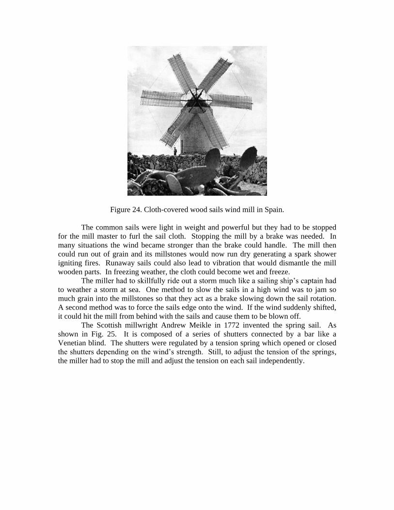
The Scottish millwright Andrew Meikle in 1772 invented the spring sail. As
shown in Fig. 25. It is composed of a series of shutters connected by a bar like a
Venetian blind. The shutters were regulated by a tension spring which opened or closed
the shutters depending on the wind’s strength. Still, to adjust the tension of the springs,
the miller had to stop the mill and adjust the tension on each sail independently.
Figure 25. Wooden shutters and their steel closing control mechanism in a wind mill,
England.
Patented self-reefing sails were invented in 1807 by Sir William Cubitt in
England. In this case, the opening and closing of the shutters could be controlled
automatically by a weight suspended outside the mill. The weight was connected to the
shutter bar by a series of rods linked to a lever called a spider. The adjustment could be
made whilst the sails were rotating.
The shutter in both spring and patent sails allowed part of the wind to pass
through them. When the wind is light, the springs closed the shutters maximizing the
drag force. In high winds they were opened minimizing it.
Wood was used in the construction of the shutters being lighter, but not as strong
as metal. Combinations of wood and metal were used with metal for the outside frame
and wood for the shutter themselves. Many sails lasted for as long as 40-50 years.
Interestingly, sails were built with a counter-clockwise rotation, a tradition that
prevails in most wind turbines today with rare exceptions.
Modern wind generators have evolved from a drag or impulse system into an
airfoil system similar to airplane propellers and wings. Wood and glass epoxy,
fiberglass, aluminum, and composite materials are now used in their construction.
CONTROL MECHANISMS
Keeping the sails pointed towards the wind was done by the mill master much like
a sailor on a sailboat. Post mills were fitted with a tail pole extending to the ground on
the side of the buck opposite the sails. Upon the wind shifting, the mill master turned the
mill by pushing the tail pole on the ground.
In the mid-1870s the fantail device was invented. It is itself a wind driven sail on
the opposite side from the main sails on the buck and perpendicular to them. If the wind
changes direction and blows on the side of the mill, it is caught by the fantail which starts
to rotate through a set of gears moving slowly in relation to its rotational speed, until it
reaches the idle position and turns the mill around to face the new wind direction. In post
mills, they are rotated around the central post. In tower and smock mills only the cap or
top is rotated. A safety mechanism would disengage the fantail if damaged, with the
rotation achieved with a hand crank until the fan tail is repaired. The gears of the fan tail
had to be lubricated on a narrow walk way.
The fantail concept was adopted in the American wind mill in which it is replaced
by a weather vane that is mounted vertically. The shifting wind strikes the sides of the
vane pushing the main blades back into the wind facing position.
In the ingenious Hallady design, the blades are attached to beams around which
they would rotate in high winds from a sail to a non-sail position slowing down the
rotation and avoiding excessive rotational speeds that could lead to its catastrophic failure
(Fig. 26).
Figure 26. Hallady wind mill in the sail and out of sail positions.
GEAR AND SHAFT SYSTEM
Figure 28. Interior gears of a French wind mill. Wood on wood friction was a cause of
frequent fires.
The wind shaft connects the sails to the mills internal parts (Fig. 27). It transmits
the force of the wind to the gears and eventually to the millstone. Strong wood or iron
was used in an octagonal or round shape tapered from the breast or front to the tail of the
mill.
Figure 28. Interior cutout model of a European wind mill yawed using a fan tail.
The brake wheel is fitted to the inner end of the wind shaft and is the largest
wheel in the mill measuring up to ten feet in diameter. The gear teeth cover its rim
driving the stone nut which then drives the millstone (Fig. 29).
The brake consisting of a ring of sections of wood surrounds the perimeter of the
brake wheel. Using a lever or a rope the mill master can clamp it down over a large
section of the moving brake wheel slowing it down or completely stopping it. This
identifies two complementary methods at the disposal of the wind master to regulate the
speed of the rotating sails:
1. The sails shutters increasing or decreasing the wind drag on the sail.
2. The wheel brake regulating the wind shaft rotation.
Careful design procedures were adopted in the design of the gear system
particularly regarding friction of metal to metal or wood to wood possibly causing fires.
Alternating the point of contacts from metal to wood reduced the fire hazard.
Figure 29. Mill grind-stone or millstone showing its grooves. They are designed to move
the ground grain from the center to the outside as a result of its rotation.
The millstones are a set of two: a lower or bed stone is stationary and the upper or
runner stone rotates (Fig. 29). The millstones were meant to crack and mill the small
grain kernels, and crushing them. Accordingly, the machinery that drove them had to
maintain a critical distance between them using screw turns or levers. A change of one
thousandth of an inch would affect the quality of the ground flour. The miller would
continuously sample the flour and adjust the screws to their best settings.
A number of grooves were cut on the millstone surface conveying the flour to its
periphery. On the lands between the grooves are fine furrows which carry out the actual
grinding process. The stones had to be removed after wearing out for dressing or re-
grooving them.
Later mills were equipped with governors consisting of belt driven rotating
weights which were pushed out by the centrifugal force out of their base as the speed
increased and consequently adjusted the distance between the milling stones
automatically.
A sack hoist consisting of a long rope or chain pulled the grain sacks from the
mill’s floor over a pulley system to a level higher than the millstone. Wind energy was
also used to hoist the grain instead of muscle power in the early machines. The grain,
once hoisted, was fed by gravity to a hopper at the millstone level of the mill (Fig. 30).
Once ground, the wheat or corn flour was carried to the lower floor and used to
fill bags or sacks for transport.
Figure 30. Elevation plan of a European wind mill.
WINDMILLS APPLICATIONS
Barley and rice hulling mills operated with hulling stones which were larger than
the common millstones removing the thin outer covering of the grain kernel. They were
grit stones with a few deep furrows with the grain flung out along them without being
ground. Requiring heavier equipment and a stronger wind location than grinding mills,
hulling mills were limited in number.
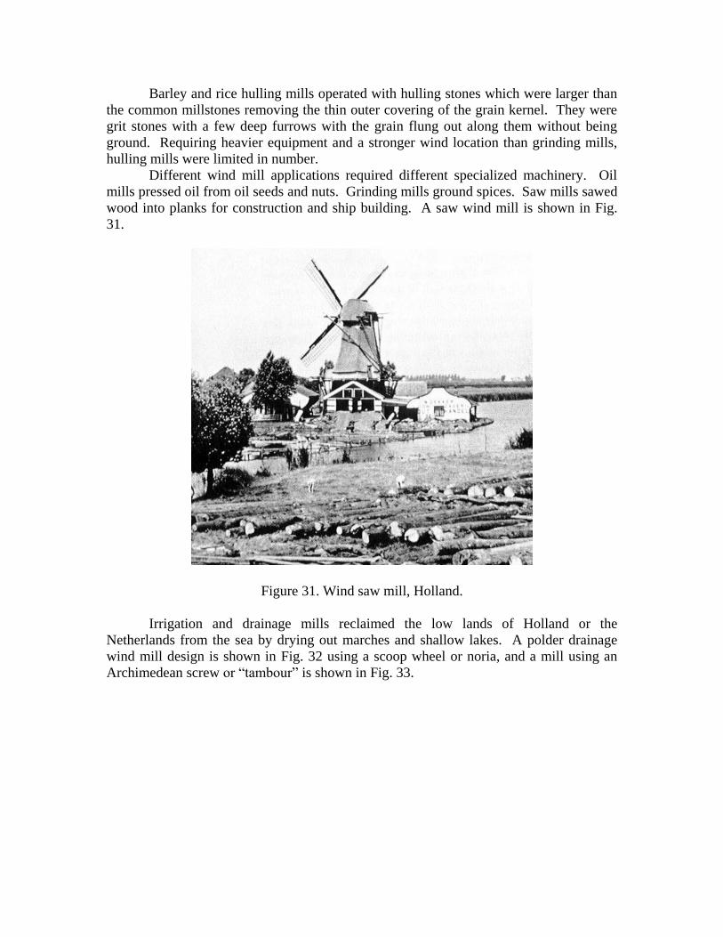
Different wind mill applications required different specialized machinery. Oil
mills pressed oil from oil seeds and nuts. Grinding mills ground spices. Saw mills sawed
wood into planks for construction and ship building. A saw wind mill is shown in Fig.
31.
Figure 31. Wind saw mill, Holland.
Irrigation and drainage mills reclaimed the low lands of Holland or the
Netherlands from the sea by drying out marches and shallow lakes. A polder drainage
wind mill design is shown in Fig. 32 using a scoop wheel or noria, and a mill using an
Archimedean screw or “tambour” is shown in Fig. 33.
Figure 32. Polder scoop wheel or noria drainage wind mill.
Figure 33. Archimedes screw wind mill for drainage and irrigation.
Figure 34. Noria or Naoura water-wheel with a 20 meters diameter and 120 water
compartments on the Orontes River at the entrance of Om Al Housn park, Hamaa, Syria.
DISCUSSION
At the beginning of the 20th century, the first modern wind mills driving electrical
generators were introduced in France by Darrieus and then spread worldwide.
The steam engine and then the internal combustion engine replaced sails on ships
and windmills. Both were more efficient than windmill using fossil fuels as a source of
energy rather than the wind.
Figure 35. Windmills preserved as tourist attractions.
However, with fossil fuels experiencing localized as well as global peaking in
their production, as well as concerns about pollution, the release of greenhouse gases,
wind machines and generators are reclaiming, with new materials, electronic controls and
advanced technology, an important share of the energy production realm in the near
future.
The world is embarking on a third industrial revolution: the Low Carbon Age; and
wind power is being reinvented to help fill the need.


![Biotech Reinvented[1]](https://static.documents.pub/doc/80x56/577d2fb91a28ab4e1eb27874/biotech-reinvented1.jpg)


