83
Wind Loads on Non‐Building Structures for the Practicing Engineer Emily Guglielmo August 29, 2017

Wind Loads on Non‐Building Structures for the Practicing Engineer
Emily GuglielmoAugust 29, 2017

1. Simplify the provisions
2. Go back to UBC
3. Stop changing
4. Improve guidance on open structures, canopies, tall parapets, PV, screenwalls.5. Already done in ASCE 7-10
“What modifications or additions would you like to see in the wind sections of ASCE 7?”
2011 NCSEA provided a survey to 9,500 engineers.
45
321

NCSEA Recommendations to ASCE 7:1. Reduce Number of Methods to one (1) Computational Method and one (1) Tabular Method.
2. Consolidate Wind Provision from ASCE 7 and IBC into ASCE 7 and simplify the provisions.
3. Provide criteria for commonly encountered conditions (Canopies, Tall Parapets, Mechanical Screens, PV Panels).
4. Provide design procedures for RTUs on buildings > 60’.
5. Simplify free‐standing wall provisions.
6. Provide guidance for irregular building configurations.

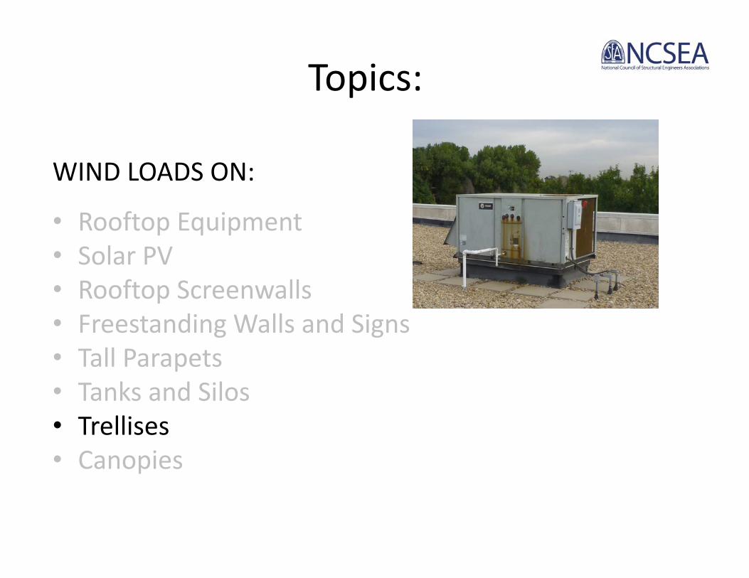
Topics:
WIND LOADS ON:
• Rooftop Equipment• Solar PV• Rooftop Screenwalls• Freestanding Walls and Signs• Tall Parapets• Tanks and Silos• Trellises• Canopies


Main Wind Force Resisting System (MWFRS)
Chapter 29: Other Structures• Conditions, Limitations• Solid Freestanding Walls or Signs• Solid Attached Signs• Wind Loads on Rooftop Structures and Equipment • Parapets• Roof Overhangs• Minimum Design Wind Loadings
ASCE 7‐10

Main Wind Force Resisting System (MWFRS)
Chapter 29: Other Structures• Scope, Conditions, Limitations• Solid Freestanding Walls and Solid Signs• Other Structures
– Rooftop Structures and Equipment – Circular Bins, Silos, and Tanks– Rooftop Solar– Parapets– Roof Overhangs– Minimum Design Wind Loadings
ASCE 7‐16
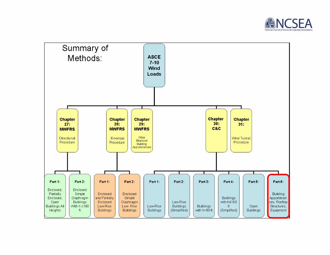

Components & Cladding (C&C)Chapter 30: Part 6:C&C for Building Appurtenances and Rooftop Structures and Equipment
•Parapets•Roof Overhangs•Rooftop Structures and Equipment
ASCE 7‐10

Components & Cladding (C&C)Chapter 30: Part 6:C&C for Building Appurtenances and Rooftop Structures and Equipment
•Parapets•Roof Overhangs•Rooftop Structures and Equipment•Attached Canopies on Buildings < 60 ft
ASCE 7‐16

Components & Cladding (C&C)Chapter 30: Part 7:C&C for Non‐Building Structures
• Circular Bins, Silos, and Tanks with h≤120 ft• Rooftop Solar Panels for Buildings of All Heights with Flat Roofs or Gable or Hip Roof with Slopes Less than 7°
ASCE 7‐16

Topics:
WIND LOADS ON:
• Rooftop Equipment• Solar PV• Rooftop Screenwalls• Freestanding Walls and Signs• Tall Parapets• Tanks and Silos• Trellises• Canopies

Rooftop EquipmentMWFRS: 29.5.2, 29.5.3 (h ≤ 60 ft)
frhh AGCqF )(
rrhv AGCqF )()( rGC1.0 ≤ ≤ 1.9,
1.0 ≤ ≤ 1.5, )( rGC

Rooftop EquipmentC&C: 30.11 (h ≤ 60 ft)
)( rhh GCqP )( rhv GCqP
)( rGC1.0 ≤ ≤ 1.9,1.0 ≤ ≤ 1.5, )( rGC

GCr
GCr=1.9Area < 10% of windward wall
GCr1.0Area = windward
wall
Rooftop Equipment for Buildings (MWFRS) (Section 29.5.1)
Office Building–Wichita, KS (V=115mph)–L = 200 ft., B = 100 ft.–Roof Height: h = 40 ft.–Roof Slope, Flat: 0.25:12–Exposure Category: C
Mechanical Unit Plan Dimensions: 10’ wide x 20’ longRTU Height: 4’ over 1’ tall curbProjected Height: 4’+1’=5’
Lateral Force: Fh= qh(GCr)Af (Eq 29.5‐2)Vertical Force: Fv= qh(GCr)Ar (Eq 29.5‐3)

Calculate qhqh calculated at mean roof height of buildingqh=0.00256KzKztKdV2
Find KhKz @ h = 40’, Exposure C Kz = 1.04 (Table 29.3‐1)

Find Kd for building Kd = 0.85 (Table 26.6‐1)

Find KztAssume Kzt=1.0

Find qh
qh= 0.00256KzKztKdV2
qh= 0.00256(1.04)(1.00)(0.85)(115)2 = 29.9 psf

HORIZONTAL WIND FORCECheck projected area of unit compared with projected area of building:B*h = 100’(40’) = 8,000 ft2
Af = 20’(5’) = 100 ft2
Af < 0.1Bh: 100 ft2< 800 ft2
GCr= 1.9
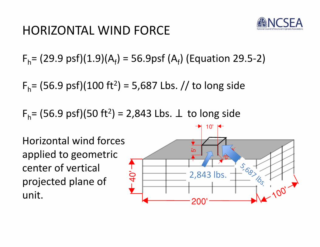
HORIZONTAL WIND FORCE
Fh= (29.9 psf)(1.9)(Af) = 56.9psf (Af) (Equation 29.5‐2)
Fh= (56.9 psf)(100 ft2) = 5,687 Lbs. // to long side
Fh= (56.9 psf)(50 ft2) = 2,843 Lbs. to long side
Horizontal wind forces applied to geometric center of vertical projected plane of unit.
2,843 lbs.
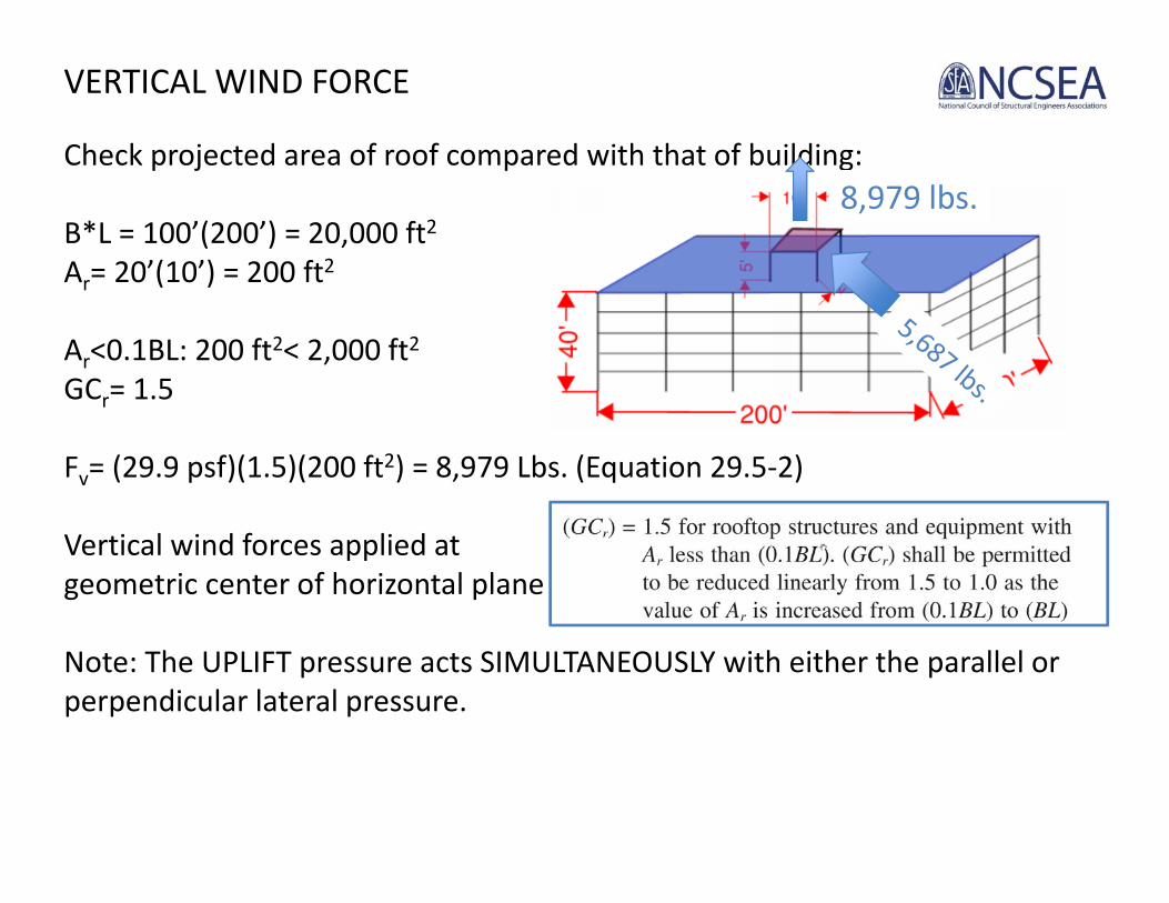
VERTICAL WIND FORCE
Check projected area of roof compared with that of building:
B*L = 100’(200’) = 20,000 ft2Ar= 20’(10’) = 200 ft2
Ar<0.1BL: 200 ft2< 2,000 ft2GCr= 1.5
Fv= (29.9 psf)(1.5)(200 ft2) = 8,979 Lbs. (Equation 29.5‐2)
Vertical wind forces applied at geometric center of horizontal plane of unit.
Note: The UPLIFT pressure acts SIMULTANEOUSLY with either the parallel or perpendicular lateral pressure.
8,979 lbs.

Rooftop Equipment for Buildings (C&C) (Section 30.11)
Loads for Designing the Equipment cabinet enclosure
Lateral C & C pressures:
Fh= 5,687 Lbs. (from previous)Fv = 8,979 Lbs. (from previous)
C & C Lateral Loads: Fh/Af= 5,687 Lbs./100 ft2 = 56.9 psf Load is applied toward or away from unit on all sides.
C & C Vertical Loads: Fv/Ar= 8,979 Lbs./200 ft2= 44.9 psf Load is applied only in the Upward direction, away from the top of the unit

What about rooftop equipment for h>60 feet?
ASCE 7‐16

Topics:
WIND LOADS ON:
• Rooftop Equipment• Solar PV• Rooftop Screenwalls• Freestanding Walls and Signs• Tall Parapets• Tanks and Silos• Trellises• Canopies

Solar PV
ASCE 7‐16

2012:‐ PV1‐2012: Seismic Design‐ PV2‐2012: Wind Design ASCE 7‐16 incorporates and adopts PV2‐2012
Solar PV• The SEAOC PV committee was formed in September 2011.
• Goal: To address the lack of requirements in the code for PV systems.
2016:‐ PV2‐2016: Supersedes PV2‐2012‐ References ASCE 7‐16‐ Knowledge from research since 2012‐ Updated terminology, effective wind area determination, wind tunnel requirements‐ In some cases, “recommended additional requirements” where the ASCE 7‐16 requirements may not be adequate.

Guide DOES Cover:‐ Arrays with tilted panels on flat or low‐slope roof buildings (Section 4)‐ Parallel‐to‐roof (flush‐mounted) arrays on sloped roofs (Section 5) ‐ Ground‐mounted solar arrays (Section 8)
Guide DOES NOT Cover:‐ Roof‐mounted systems with tilted panels that are not low‐profile‐ Arrays on other roof shapes (e.g. hip, gable, saw‐tooth, etc.)

Solar PV

SEAOC PV2‐2016 Examples
Steps:• Roof wind zones• Normalized wind area (An)• Nominal net pressure coefficient ((GCrn)nom)• Parapet factor (P)• Chord factor (C)• Edge factor (E)• Effective wind area (A) and design wind pressure (p) • Design of an unattached (ballast‐only) array to resist uplift • Design of an unattached (ballast‐only) array to resist sliding • Parallel‐to‐roof (flush‐mounted) modules

Topics:
WIND LOADS ON:
• Rooftop Equipment• Solar PV• Rooftop Screenwalls• Freestanding Walls and Signs• Tall Parapets• Tanks and Silos• Trellises• Canopies

Rooftop Screenwalls
Poll: What wind pressure do you use to design a rooftop screenwall?
a)Rooftop Structures and Equipment?
b) Solid Freestanding Sign with Adjustment?
c) Parapet Pressures?

Rooftop ScreenwallASCE 7‐16: New CommentaryC29.5.1: Mechanical equipment screens commonly are used to conceal plumbing, electrical ormechanical equipment from view and are defined as rooftop structures.. located away from theedge of the building roof such that they are not considered parapets… little research is availableto provide guidance for determining wind loads on screen walls and equipment behind screens.Accordingly, rooftop screens.. should be designed for the full wind load determined inaccordance with Section 29.5.1. Where substantiating data have been obtained using the WindTunnel Procedure, design professionals may consider wind load reductions in the design ofrooftop screens.

What about equipment behind rooftop screens? Appropriate to consider
shielding?

Phase 1 IBHS Research Center & ASHRAE Testing: Preliminary Findings
• Equipment height above top of screen increases wind loads.
• Fully enclosed configurations lower wind loads.• Partially enclosed screen configurations do not provide significant wind load reduction.
• Screen type does not significantly change wind loads.

Phase 2 IBHS Research Center & ASHRAE Testing
• Evaluate wind loads on screenwalls themselves.

Topics:
WIND LOADS ON:
• Rooftop Equipment• Solar PV• Rooftop Screenwalls• Freestanding Walls and Signs• Tall Parapets• Tanks and Silos• Trellises• Canopies

Solid Freestanding Walls and Signs

Solid Freestanding Walls and Signs

Solid Freestanding Walls and Signs

Solid Freestanding Walls and Signs
Solid Freestanding Walls and Signs

Solid Sign at Ground Level (Exposure C, 115 mph)
30’ Wide x 10’ High s=10’, B=30’, h=10’
Kh = 0.85 (Table 29.3-1)Kd= 0.85 (Table 26.6-1)Kzt=1.0 (assumed)
qh= 0.00256 KhKztKdV2
qh= 0.00256(0.85)(1.00)(0.85)(115)2= 24.5 psf
G = 0.85 (Section 26.9 – Rigid Structure)
F = qhGCfAs(lb) (Eq 29.4-1)

Figure 29.4-1 for Cf
For B/s = 2: Cf= 1.40 Interpolating for B/s 3.0, Cf= 1.375For B/s = 4: Cf= 1.35
0.1'10'10
0.3'10'30
hssB
Aspect Ratio
Clearance Ratio

Figure 29.4-1 for Cf
F = qhGCfAs (Eq 29.4-1)
F = (24.5 psf)(0.85)(1.375)As= 28.59 psf*As
As= B x s = 30’x10’ = 300 ft2
F= 28.6 psf*As = 28.6 psf(300 ft2) = 8,577 Lbs.
Case A
For CASE A, Load is applied at plan center and at (s/2)+(0.05h)
= 5.5’ above base.

Case B
For CASE B, load is applied at 5.5’ above base and at
0.2B offset from either side of plan centerline.
0.2B = 0.2(30’) = 6.0’ either side of plan centerline.

Case B
For CASE B, load is applied at 5.5’ above base and at
0.2B offset from either side of plan centerline.
0.2B = 0.2(30’) = 6.0’ either side of plan centerline.

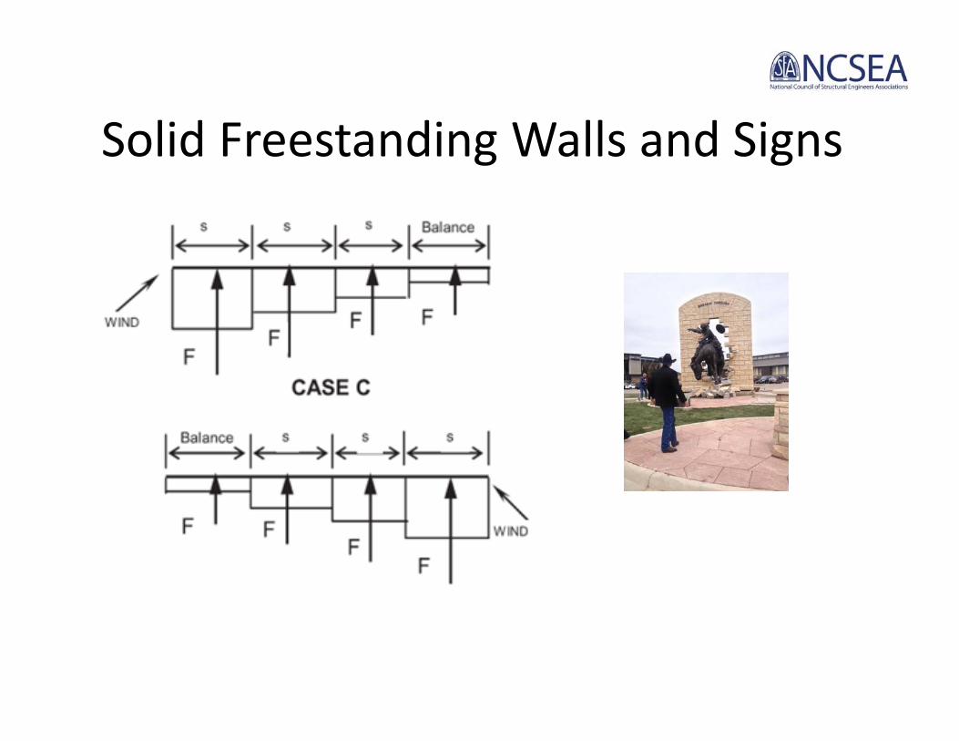
Check if CASE C must be considered (note 3, Figure 29.4-1)
If B/s ≥ 2.0, CASE C must be considered.
Consider CASE C.
0.20.3'10'30
sB
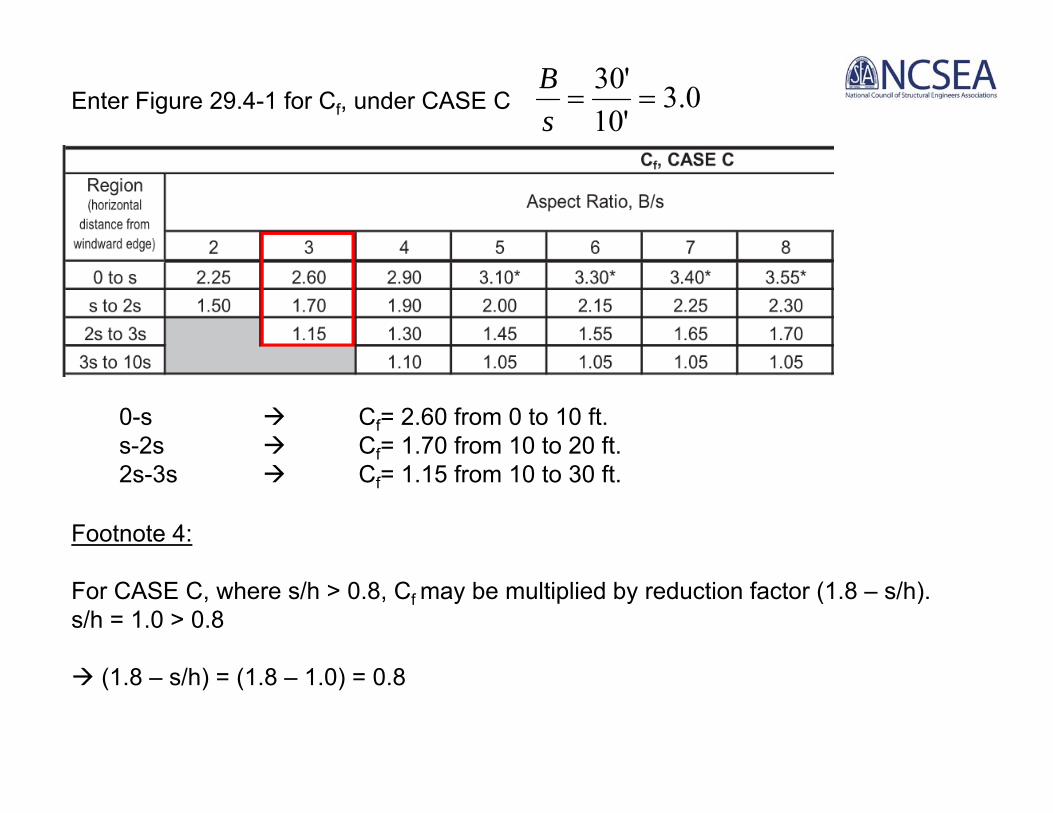
Enter Figure 29.4-1 for Cf, under CASE C
0-s Cf= 2.60 from 0 to 10 ft.s-2s Cf= 1.70 from 10 to 20 ft.2s-3s Cf= 1.15 from 10 to 30 ft.
Footnote 4:
For CASE C, where s/h > 0.8, Cf may be multiplied by reduction factor (1.8 – s/h).s/h = 1.0 > 0.8
(1.8 – s/h) = (1.8 – 1.0) = 0.8
0.3'10'30
sB

F = qhGCfAs (Eq 29.4-1)
F1 = (24.5 psf)(0.85)(2.60)(0.8)(10’x10’) = 4,324 lbs.F2 = (24.5 psf)(0.85)(1.70)(0.8)(10’x10’) = 2,828 lbs.F3 = (24.5 psf)(0.85)(1.15)(0.8)(10’x10’) = 1,913 lbs.
For CASE C, apply F1, F2, and F3 at plan centerline of each
length, s.
Apply F1, F2 and F3 at 5.5’ above base.
Case C

Solid Freestanding Walls and Signs: ASCE 7‐16
• New research and provision cover deeper signs (electronic).
• Minor revisions to the provisions.

Topics:
WIND LOADS ON:
• Rooftop Equipment• Solar PV• Rooftop Screenwalls• Freestanding Walls and Signs• Tall Parapets• Tanks and Silos• Trellises• Canopies

Tall Parapets

Tall Parapets

Tall Parapets

Tall Parapets

History of Parapet Design
• Before ASCE 7‐02 there were no provisions for wind loads on parapets.
• ASCE 7‐02 a method was introduced based on “the committee’s collective experience, intuition, and judgement”.
• ASCE 7‐05 provisions were updated with research from University of Western Ontario and Concordia University.
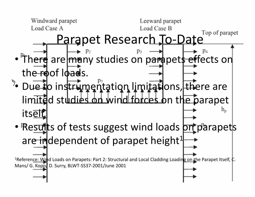
Parapet Research To‐Date• There are many studies on parapets effects on the roof loads.
• Due to instrumentation limitations, there are limited studies on wind forces on the parapet itself.
• Results of tests suggest wind loads on parapets are independent of parapet height1
1Reference: Wind Loads on Parapets: Part 2: Structural and Local Cladding Loading on the Parapet Itself, C. Mans/ G. Kopp/ D. Surry, BLWT‐SS37‐2001/June 2001

Tall Parapets

Topics:
WIND LOADS ON:
• Rooftop Equipment• Solar PV• Rooftop Screenwalls• Freestanding Walls and Signs• Tall Parapets• Tanks and Silos• Trellises• Canopies

ASCE 7‐16 – Silos & Tanks• Current provisions are based on ANSI A58.1 – 1982.• Current provisions are based on a “drag” coefficient approach
• New provisions are based on the Australian Standard
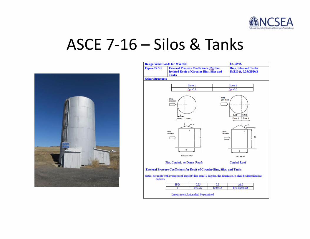
ASCE 7‐16 – Silos & Tanks
Topics:
WIND LOADS ON:
• Rooftop Equipment• Solar PV• Rooftop Screenwalls• Freestanding Walls and Signs• Tall Parapets• Tanks and Silos• Trellises• Canopies

Wind Load on Trellis

Wind Trib = 6” tall x 30’ long = 15 ft2Total Force = 20 psf x 15 ft2 = 300 lbs.
Wind Trib = 6” tall x 30’ long x 50 slats= 750 ft2Total Force = 20 psf x 750 ft2 = 15,000 lbs.


~2 x height air flow has reattached and should be considered
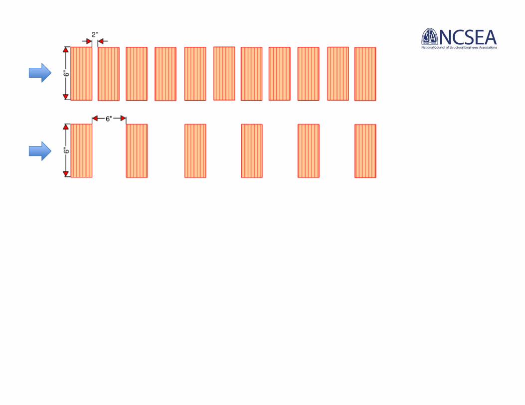
~2 x height air flow has reattached and should be considered
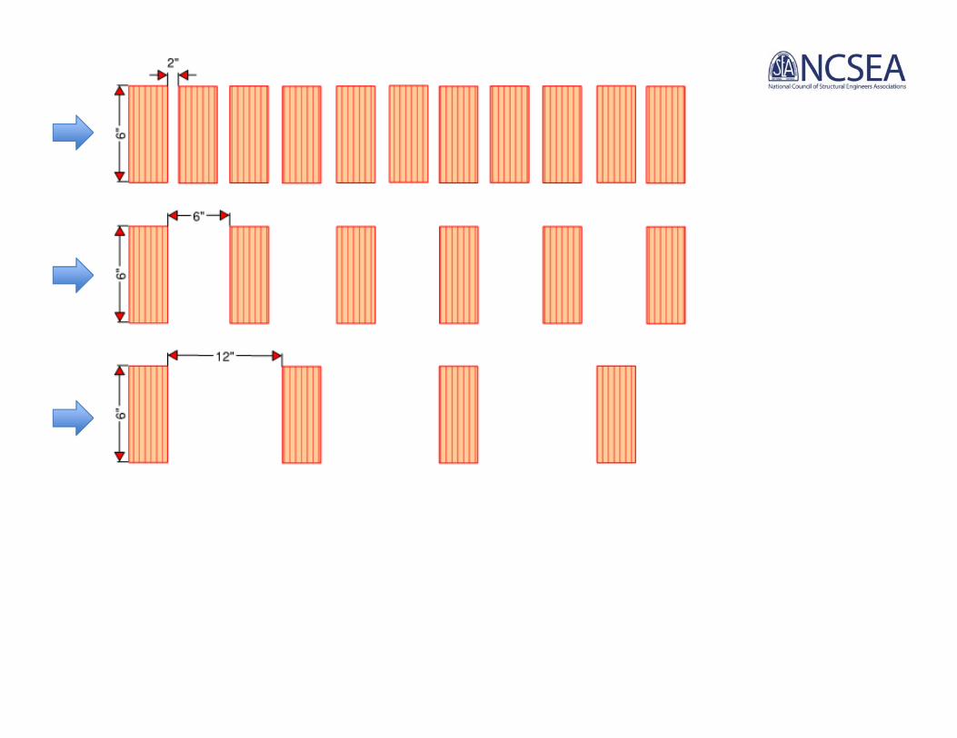
~2 x height air flow has reattached and should be considered

~2 x height: air flow has
reattached and should be considered

Topics:
WIND LOADS ON:
• Rooftop Equipment• Solar PV• Rooftop Screenwalls• Freestanding Walls and Signs• Tall Parapets• Tanks and Silos• Trellises• Canopies
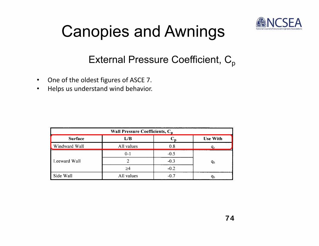
External Pressure Coefficient, Cp
• One of the oldest figures of ASCE 7. • Helps us understand wind behavior.
Canopies and Awnings
74

75
Down-draft effect of wind flowing down building
Use Cp=0.80 (same as windward wall) on the top of
canopy
Canopies and Awnings
Canopies and Awnings
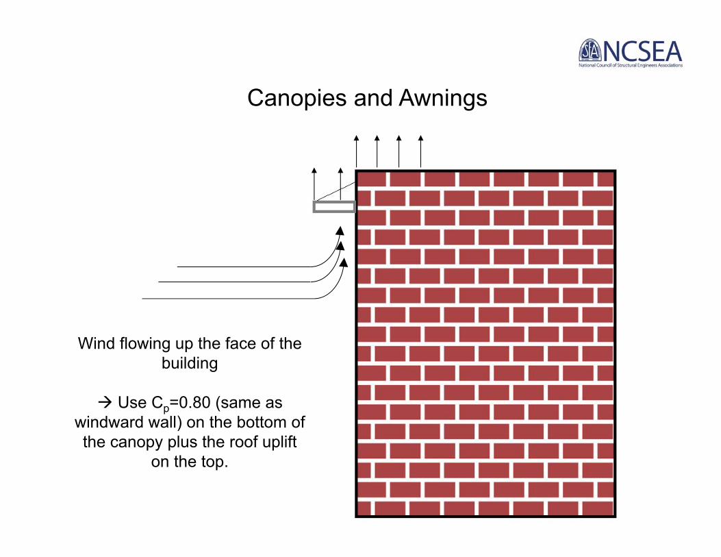
Wind flowing up the face of the building
Use Cp=0.80 (same as windward wall) on the bottom of the canopy plus the roof uplift
on the top.

ASCE 7‐16 – Attached Canopies

ASCE 7‐16 – Attached Canopies

Additional Resources• Wind Loads for Petrochemical and Other Industrial Facilities
• SEAOC Wind Design for Low‐Profile Solar Photovoltaic Arrays on Flat Roofs

Additional Resources• Guide Specifications for Design of Metal Flagpoles, ANSI/NAAMM FP1001‐97, 4th Edition
• Structural Standards for Steel Antenna Towers and Antenna Supporting Structures, ANSI/TIA‐222‐G
Additional Resources• Wind Loads on Small Roof‐Mounted Air‐Conditioning Units, IBHS Research Center

Questions?

Summary• There are attempts to address commonly encountered conditions (canopies, h>60’, screenwalls, solar PV).
• Even when the code doesn’t address an issue, we can extrapolate to find a solution.
• Use resources from related industries for guidance on non‐building wind loads.
Emily [email protected]
415‐814‐0030


