NREL is a national laboratory of the U.S. Department of Energy Office of Energy Efficiency and Renewable Energy operated by the Alliance for Sustainable Energy, LLC Eduard Muljadi NREL, Golden CO [email protected]UWIG-EnerNex Modeling Workshop Albany, NY July 5-6, 2011 Wind Power Generation Power Flow and Dynamic Modeling Vadim Zheglov EnerNex, Tennessee [email protected]
Transcript
NREL is a national laboratory of the U.S. Department of Energy Office of Energy Efficiency and Renewable Energy operated by the Alliance for Sustainable Energy, LLC
NREL is a national laboratory of the U.S. Department of Energy Office of Energy Efficiency and Renewable Energy operated by the Alliance for Sustainable Energy, LLC
Background
NREL is a national laboratory of the U.S. Department of Energy Office of Energy Efficiency and Renewable Energy operated by the Alliance for Sustainable Energy, LLC
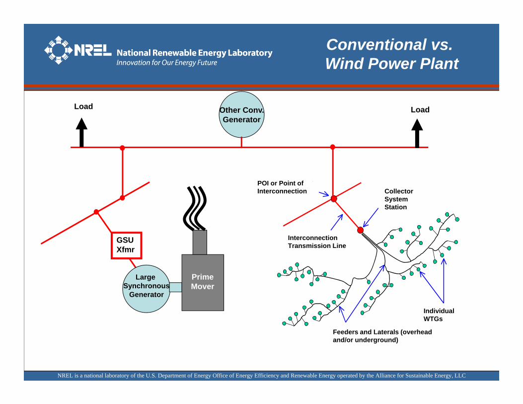
Conventional vs. Wind Power Plant
GSUXfmr
Large Synchronous
Generator
PrimeMover
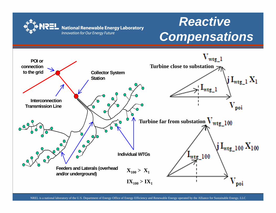
POI or connection to the grid Collector System
Station
Feeders and Laterals (overhead and/or underground)
Individual WTGs
Interconnection Transmission Line
Other Conv.Generator
LoadLoad
POI or Point of Interconnection Collector
SystemStation
InterconnectionTransmission Line
Feeders and Laterals (overheadand/or underground)
Individual WTGs
NREL is a national laboratory of the U.S. Department of Energy Office of Energy Efficiency and Renewable Energy operated by the Alliance for Sustainable Energy, LLC
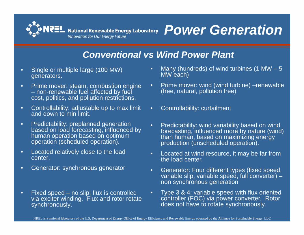
Power GenerationConventional vs Wind Power Plant
• Many (hundreds) of wind turbines (1 MW – 5 MW each)
• Predictability: wind variability based on wind forecasting, influenced more by nature (wind) than human, based on maximizing energy production (unscheduled operation).
• Located at wind resource, it may be far from the load center.
• Generator: Four different types (fixed speed, variable slip, variable speed, full converter) –non synchronous generation
• Type 3 & 4: variable speed with flux oriented controller (FOC) via power converter. Rotor does not have to rotate synchronously.
• Single or multiple large (100 MW) generators.
• Prime mover: steam, combustion engine – non-renewable fuel affected by fuel cost, politics, and pollution restrictions.
• Controllability: adjustable up to max limit and down to min limit.
• Predictability: preplanned generation based on load forecasting, influenced by human operation based on optimum operation (scheduled operation).
• Located relatively close to the load center.
• Generator: synchronous generator
• Fixed speed – no slip: flux is controlled via exciter winding. Flux and rotor rotate synchronously.
NREL is a national laboratory of the U.S. Department of Energy Office of Energy Efficiency and Renewable Energy operated by the Alliance for Sustainable Energy, LLC
Four basic topologies based on grid interface:– Type 1 – conventional induction generator– Type 2 – wound-rotor induction generator with variable rotor
resistance– Type 3 – doubly-fed induction generator– Type 4 – full converter interface
generator
full power
PlantFeeders
actodc
dctoac
generator
partial power
PlantFeeders
actodc
dctoac
generator
Slip poweras heat loss
PlantFeeders
PF controlcapacitor s
actodc
generator
PlantFeeders
PF controlcapacitor s
Type 1 Type 2 Type 3 Type 4
Power Generation
Types of Wind Turbine Generator
NREL is a national laboratory of the U.S. Department of Energy Office of Energy Efficiency and Renewable Energy operated by the Alliance for Sustainable Energy, LLC
Power Flow ModelingWind Turbine Generator
NREL is a national laboratory of the U.S. Department of Energy Office of Energy Efficiency and Renewable Energy operated by the Alliance for Sustainable Energy, LLC
WPP Representation
POI or connection to the grid Collector System
Station
Feeders and Laterals (overhead and/or underground)
Individual WTGs
Interconnection Transmission Line
Collector System Equivalent
jXeqReq
Beq/2 Beq/2
NREL is a national laboratory of the U.S. Department of Energy Office of Energy Efficiency and Renewable Energy operated by the Alliance for Sustainable Energy, LLC
Equivalencing
NREL is a national laboratory of the U.S. Department of Energy Office of Energy Efficiency and Renewable Energy operated by the Alliance for Sustainable Energy, LLC
Equivalencing
NREL is a national laboratory of the U.S. Department of Energy Office of Energy Efficiency and Renewable Energy operated by the Alliance for Sustainable Energy, LLC
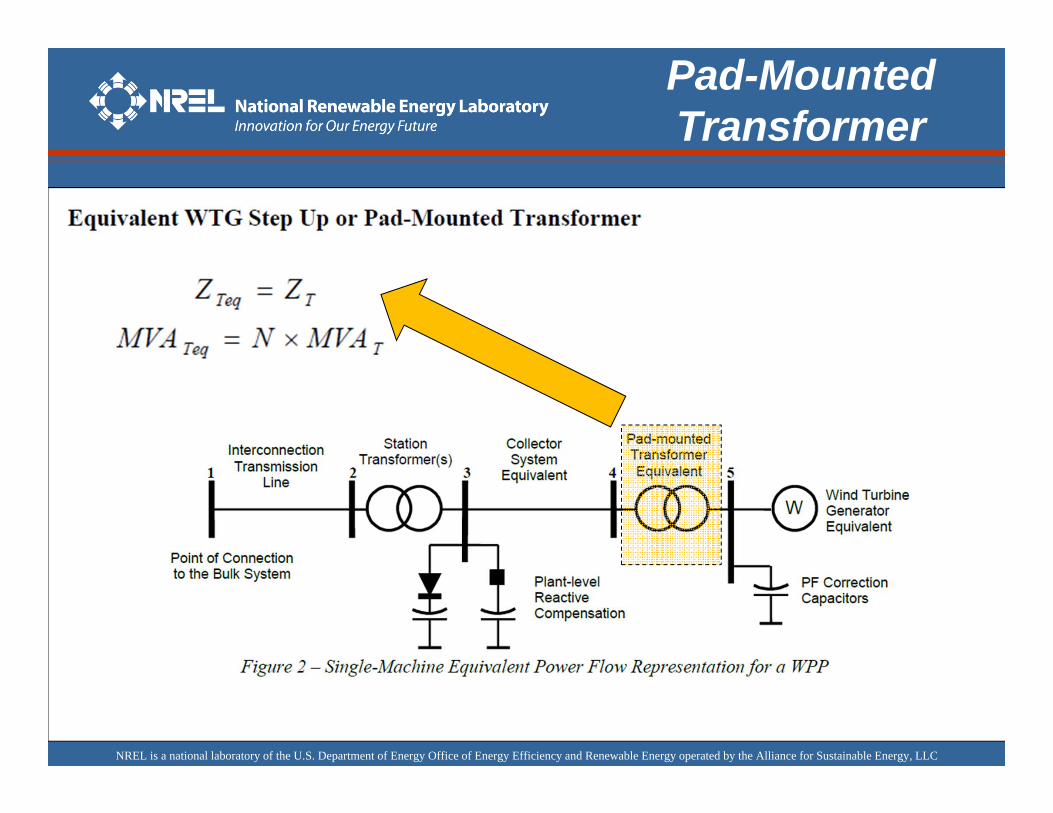
Pad-MountedTransformer
NREL is a national laboratory of the U.S. Department of Energy Office of Energy Efficiency and Renewable Energy operated by the Alliance for Sustainable Energy, LLC
Reactive Compensations
Represented bySeparate Model
Type 1 and 2 WTGs are induction machines:
• Several stages of capacitors banks at the WTG terminals are normally applied . Net power factor at bus 5 ~ 1.0
• In power flow: • modeled as fixed shunt devices• WTG of type 1 is approximately PF=0.9 therefore the capacitor need is about to be ½ of the power output. • example, for a 100 MW WPP at full output, Qmin = Qmax = -50 Mvar• and add a 50 Mvar shunt capacitor at the WTG terminals.
• Plant level reactive compensation may still be installed to meet interconnection requirements and should be explicitly represented in power flow.
NREL is a national laboratory of the U.S. Department of Energy Office of Energy Efficiency and Renewable Energy operated by the Alliance for Sustainable Energy, LLC
Reactive Compensations
Type 3 and Type 4 WTGs (an estimate to start depending on the terminal voltage)
• These WTGs are capable of adjusting power factor to a desired value within the rating of the generator and converter. They are also capable of voltage control at the interconnection point or at its terminals.
• External reactive power compensation is often required to meet interconnection requirements
• If these WTGs do not participate in voltage control, the equivalent generator should be assigned a fixed power factor, typically unity. (i.e., Qmin = Qmax = 0).
• If the WTGs do participate in voltage control, then the equivalent generator should be assigned a reactive capability approximately equal to the aggregate WTG reactive power range (i.e., Qmin = -Srated tan(cos-1(0.90); and Qmax = Srated tan(cos-1(0.95)) ).
• For example, consider a 100 MW WPP that employs Type 4 WTGs with specified power factor range +/-0.95 at full output. In this example, Qmin should be set to -33 Mvar and Qmax should be set to +33 Mvar. At an output level below rated, the reactive limits should be adjusted according to the WTG capability curve.
NREL is a national laboratory of the U.S. Department of Energy Office of Energy Efficiency and Renewable Energy operated by the Alliance for Sustainable Energy, LLC
Reactive PowerFlow
+
VA
-
jI X+
VB
-
VA = VB
QA =QB= 0.5 I2X
A
B
A = B
All Q comes from A
QA =I2X ; QB= 0
VA > VB ; B = 0 VB = 1.0
VA
jI XI
QB =I2X ; QA= 0
VA < VB; A = 0VB = 1.0
VA
jI XIA B
VA
II”
VA”VA
II’
VA’
VB = 1.0 VB”= 1.1
Equal Q (VAR) contribution
All Q comes from B
Overexcited VA’ > VA ; QA =I’2X ; QB< 0
I
VA= 1.0
jI XI
VB = 1.0
NREL is a national laboratory of the U.S. Department of Energy Office of Energy Efficiency and Renewable Energy operated by the Alliance for Sustainable Energy, LLC
POI or connection to the grid Collector System
Station
Feeders and Laterals (overhead and/or underground)
Individual WTGs
Interconnection Transmission Line
X100 > X1
IX100 > IX1
Reactive Compensations
Turbine far from substation
Turbine close to substation
NREL is a national laboratory of the U.S. Department of Energy Office of Energy Efficiency and Renewable Energy operated by the Alliance for Sustainable Energy, LLC
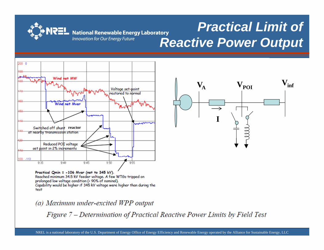
Practical Limit of Reactive Power Output
• Due to collector system effects, some WTGs in the WPP will actually reach terminal voltage limits before reaching the nameplate reactive power limits.
• The net effect is that actual reactive power capability could be less than the nameplate.
• The reactive power capability can be determined by field test or careful observation of WPP performance during abnormally high or low system voltage.
• For example, Figure 7 shows the results of field tests to determine the practical reactive limits of a 200 MW WPP.
• All measurements were made at the interconnection point. Taking into account the effect of transformer and collector system impedances, the reactive power limits of the equivalent WTG can be established.
• Currently, there are no industry standard guidelines for testing WPP steady-state reactive limits.
NREL is a national laboratory of the U.S. Department of Energy Office of Energy Efficiency and Renewable Energy operated by the Alliance for Sustainable Energy, LLC
+95 and
Practical Limit of Reactive Power Output
reactor
VPOI
I
VAVinf
NREL is a national laboratory of the U.S. Department of Energy Office of Energy Efficiency and Renewable Energy operated by the Alliance for Sustainable Energy, LLC
Practical Limit of Reactive Power Output
VPOI
I
VAVinf
NREL is a national laboratory of the U.S. Department of Energy Office of Energy Efficiency and Renewable Energy operated by the Alliance for Sustainable Energy, LLC
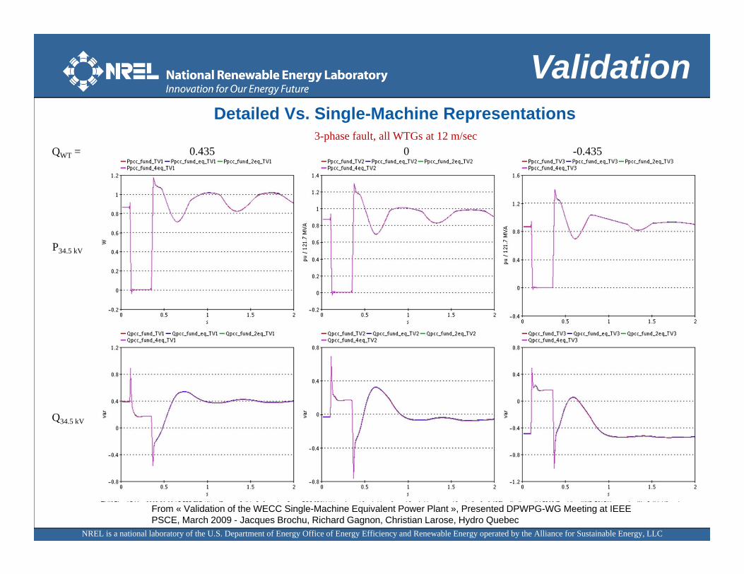
P34.5 kV
Q34.5 kV
QWT = 0.435 0 -0.4353-phase fault, all WTGs at 12 m/sec
From « Validation of the WECC Single-Machine Equivalent Power Plant », Presented DPWPG-WG Meeting at IEEE PSCE, March 2009 - Jacques Brochu, Richard Gagnon, Christian Larose, Hydro Quebec
Detailed Vs. Single-Machine Representations
Validation
NREL is a national laboratory of the U.S. Department of Energy Office of Energy Efficiency and Renewable Energy operated by the Alliance for Sustainable Energy, LLC
ValidationDetailed Vs. Single-Machine Representations
From « Validation of the WECC Single-Machine Equivalent Power Plant », Presented DPWPG-WG Meeting at IEEE PSCE, March 2009 - Jacques Brochu, Richard Gagnon, Christian Larose, Hydro Quebec
P34.5 kV
Q34.5 kV
0.435 0 -0.435
4 feeders = Typical
1 and 2 feeders
2 and 4 feeders = Typical
1 feeder
QWT =3-phase fault, different wind speed for each feeder
NREL is a national laboratory of the U.S. Department of Energy Office of Energy Efficiency and Renewable Energy operated by the Alliance for Sustainable Energy, LLC
Wind Power PlantNetwork
Gen
100 MW equivalent wind turbine generator
Infinite Bus
Ideal Gen
230 kV Line 1
R1, X1, B1
230 kV Line 2
R2, X2, B2
34.5 kV collector system equivalentRe, Xe, Be
0.6/34.4kV equivalent GSU transformer
Rte, Xte
34.4/230 kV station transformer
Rt, Xt.
Station‐level shunt compensation
Turbine‐level shunt compensation
21 34
5
NREL is a national laboratory of the U.S. Department of Energy Office of Energy Efficiency and Renewable Energy operated by the Alliance for Sustainable Energy, LLC
Power Flow
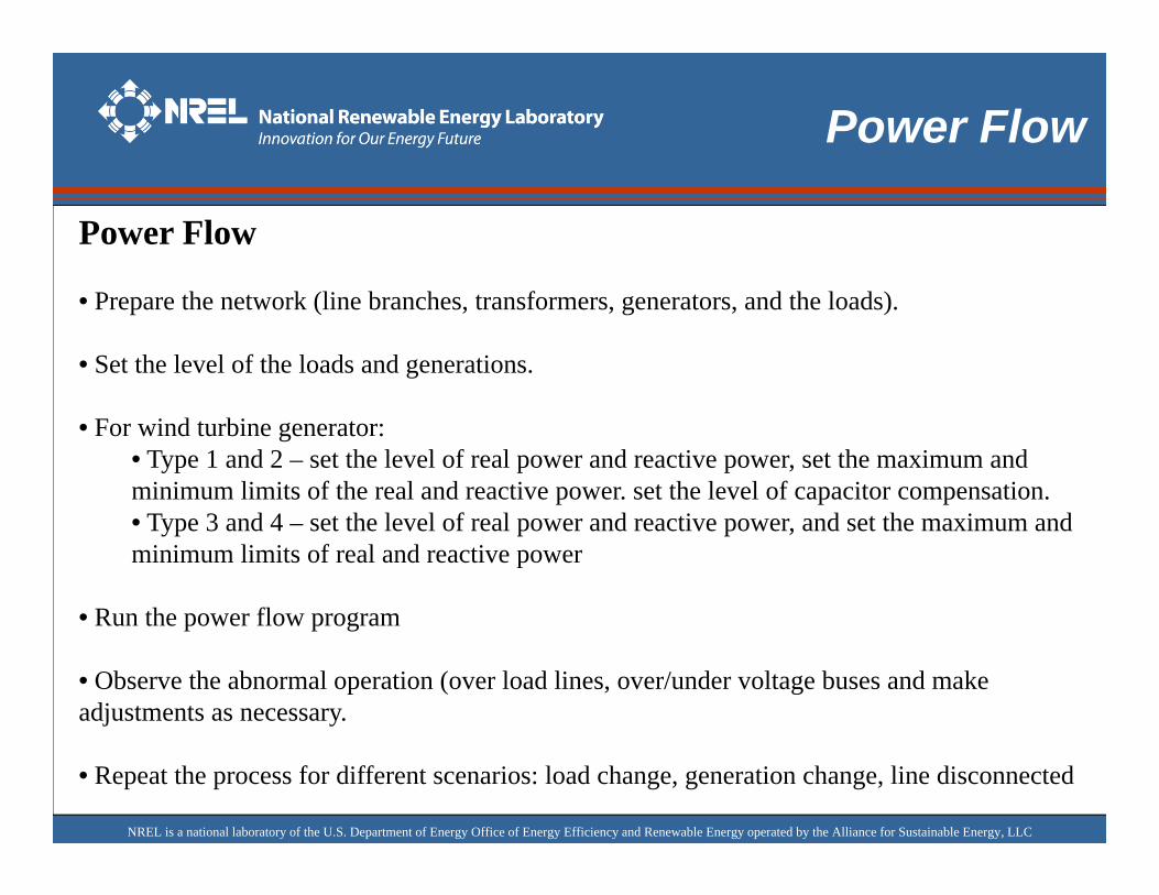
Power Flow
• Prepare the network (line branches, transformers, generators, and the loads).
• Set the level of the loads and generations.
• For wind turbine generator:• Type 1 and 2 – set the level of real power and reactive power, set the maximum and minimum limits of the real and reactive power. set the level of capacitor compensation.• Type 3 and 4 – set the level of real power and reactive power, and set the maximum and minimum limits of real and reactive power
• Run the power flow program
• Observe the abnormal operation (over load lines, over/under voltage buses and make adjustments as necessary.
• Repeat the process for different scenarios: load change, generation change, line disconnected
NREL is a national laboratory of the U.S. Department of Energy Office of Energy Efficiency and Renewable Energy operated by the Alliance for Sustainable Energy, LLC
Power FlowData
NREL is a national laboratory of the U.S. Department of Energy Office of Energy Efficiency and Renewable Energy operated by the Alliance for Sustainable Energy, LLC
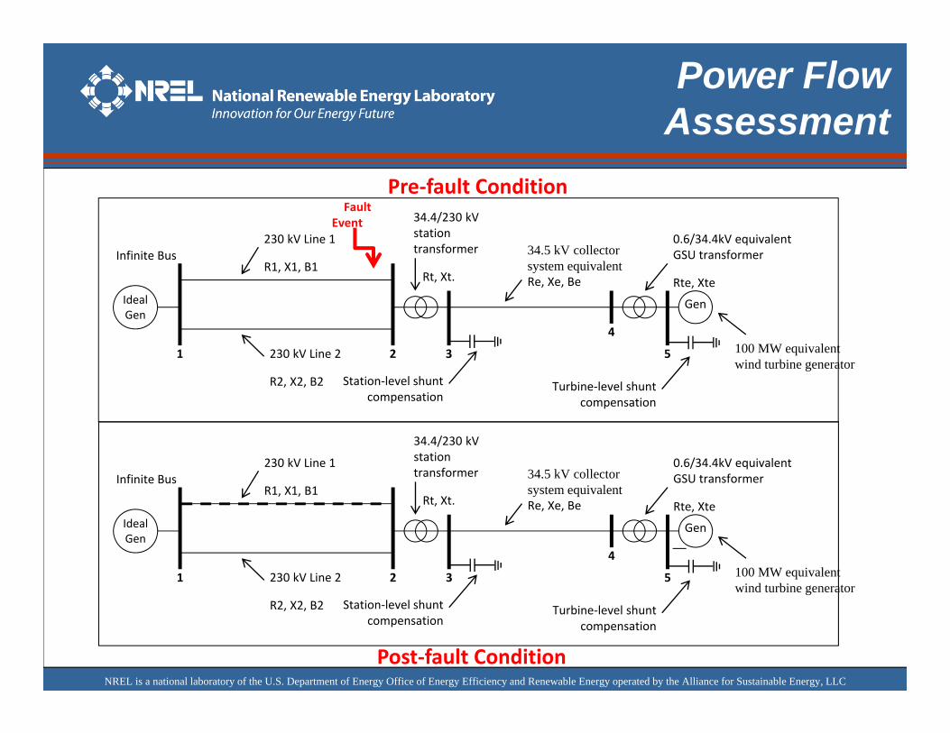
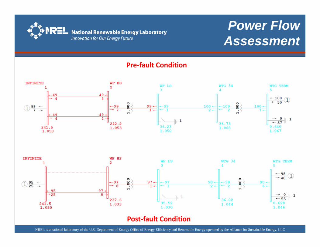
Power FlowAssessment
Gen
100 MW equivalent wind turbine generator
Infinite Bus
Ideal Gen
230 kV Line 1
R1, X1, B1
230 kV Line 2
R2, X2, B2
34.5 kV collector system equivalentRe, Xe, Be
0.6/34.4kV equivalent GSU transformer
Rte, Xte
34.4/230 kV station transformer
Rt, Xt.
Station‐level shunt compensation
Turbine‐level shunt compensation
21 3
4
5
Fault Event
Pre‐fault Condition
Post‐fault Condition
Gen
100 MW equivalent wind turbine generator
Infinite Bus
Ideal Gen
230 kV Line 1
R1, X1, B1
230 kV Line 2
R2, X2, B2
34.5 kV collector system equivalentRe, Xe, Be
0.6/34.4kV equivalent GSU transformer
Rte, Xte
34.4/230 kV station transformer
Rt, Xt.
Station‐level shunt compensation
Turbine‐level shunt compensation
21 3
4
5
NREL is a national laboratory of the U.S. Department of Energy Office of Energy Efficiency and Renewable Energy operated by the Alliance for Sustainable Energy, LLC
Post‐fault Condition
Power FlowAssessment
Pre‐fault Condition
NREL is a national laboratory of the U.S. Department of Energy Office of Energy Efficiency and Renewable Energy operated by the Alliance for Sustainable Energy, LLC
Dynamic ModelingWind Turbine Generator
NREL is a national laboratory of the U.S. Department of Energy Office of Energy Efficiency and Renewable Energy operated by the Alliance for Sustainable Energy, LLC
Dynamic ModelingNeeds
Dynamic models are needed to study the dynamic behavior of power system. Users include system planners and operators, generation developers, equipment manufacturers, researchers, and consultants.
Wind Power Plant (WPP) models are needed to study the impact of proposed or existing wind power plants on power system and vice versa (i.e. to keep voltage and frequency within acceptable limits).
Models need to reproduce WPP behavior during transient events such as faults/clear events, generation/load tripping, etc.
G1G2
G3
WTGwind turbine generator
newline
lossofline
Resizing
ShortCircuit
NREL is a national laboratory of the U.S. Department of Energy Office of Energy Efficiency and Renewable Energy operated by the Alliance for Sustainable Energy, LLC
Dynamic ModelingCheck List
Check List:
• Prepare the power flow model and run the power flow to ensure that the pre-fault and post-fault condition results are acceptable and makes sense.
• For wind turbine generator:• Prepare the wind turbine dynamic model to be represented• If the wind turbine parameters (of the WECC generic models) are not available from the turbine manufacturers, use the default data provided by the generic models available from the WECC website• If the wind turbine parameters (of the WECC generic models) of the turbines to be simulated are available from the turbine manufacturers, use the latest model parameters provided.
• Prepare the dynamic script of the scenario of interests and run the dynamic simulation for the contingencies fault, loss of lines, etc.) to be investigated.
NREL is a national laboratory of the U.S. Department of Energy Office of Energy Efficiency and Renewable Energy operated by the Alliance for Sustainable Energy, LLC
Dynamic ModelingTime Scale
Switching Transients
Subsynchronous Resonance
Transient Stability
Oscillatory Stability
Long-term Dynamics
TIME (seconds)
10-6 10-5 10-4 .001
1 cycle
104.1 1 10 100 1000
1 minute 1 hour
.01
Source: Dynamic Simulation Applications Using PSLF – Short Course Note – GE Energy
NREL is a national laboratory of the U.S. Department of Energy Office of Energy Efficiency and Renewable Energy operated by the Alliance for Sustainable Energy, LLC
Dynamic ModelsWECC Generic Models
Generic model development in PSSE/PSLF– Complete suite of prototype models implemented
Current focus– Model validation & refinement (e.g., freq. response)– Identification of generic model parameters for different
manufacturers (at NREL)
Model Type Type 1 Type 2 Type 3 Type 4Generator wt1g wt2g wt3g wt4gExcitation / Controller wt2e wt3e wt4eTurbine wt1t wt2t wt3t wt4tPitch Controller wt1p wt2p wt3p wt4p
NREL is a national laboratory of the U.S. Department of Energy Office of Energy Efficiency and Renewable Energy operated by the Alliance for Sustainable Energy, LLC
Dynamic ModelsWTG Type 1 and 2
generator
Slip poweras heat loss
PlantFeeders
PF controlcapacitor s
actodc
generator
PlantFeeders
PF controlcapacitor s
Type 1 WTG Type 2 WTG
NREL is a national laboratory of the U.S. Department of Energy Office of Energy Efficiency and Renewable Energy operated by the Alliance for Sustainable Energy, LLC
Dynamic ModelsWTG Type 3 and 4
generator
partia l power
PlantFeeders
actodc
dctoac
generator
full power
PlantFeeders
actodc
dctoac
Type 3 WTG Type 4 WTG
NREL is a national laboratory of the U.S. Department of Energy Office of Energy Efficiency and Renewable Energy operated by the Alliance for Sustainable Energy, LLC
Single TurbineRepresentation
W
Pad-mounted Transformer Equivalent
Wind Turbine Generator Equivalent
PF CorrectionShunt Capacitors
Collector System
Equivalent
Interconnection Transmission Line
-Plant-level Reactive Compensation
POI or Connection to the Transmission
System
Station Transformer(s)
Major components of WPP Equivalent Representation:
• Wind Turbine Generator (WTG) Equivalent and power factor correction (PFC) caps• Plant level reactive power compensation if applicable• Pad-mounted Transformer Equivalent• Collector System Equivalent branch.
NREL is a national laboratory of the U.S. Department of Energy Office of Energy Efficiency and Renewable Energy operated by the Alliance for Sustainable Energy, LLC
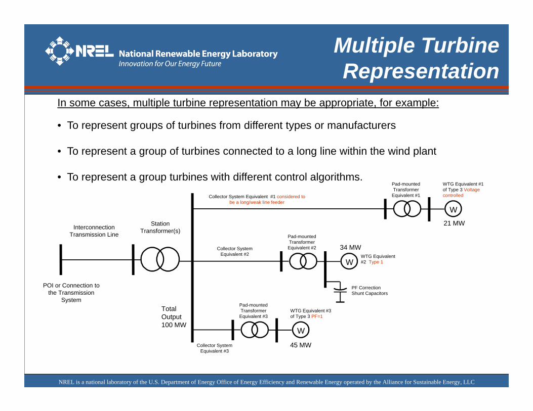
Multiple Turbine Representation
In some cases, multiple turbine representation may be appropriate, for example:
• To represent groups of turbines from different types or manufacturers
• To represent a group of turbines connected to a long line within the wind plant
• To represent a group turbines with different control algorithms.
W
Pad-mounted Transformer
Equivalent #2
WTG Equivalent #2 Type 1
PF CorrectionShunt Capacitors
Collector System Equivalent #2
Interconnection Transmission Line
POI or Connection to the Transmission
System
Station Transformer(s)
W
Pad-mounted Transformer
Equivalent #1
WTG Equivalent #1 of Type 3 Voltage controlledCollector System Equivalent #1 considered to
be a long/weak line feeder
W
Pad-mounted Transformer
Equivalent #3WTG Equivalent #3 of Type 3 PF=1
Collector System Equivalent #3
21 MW
34 MW
45 MW
Total Output100 MW
NREL is a national laboratory of the U.S. Department of Energy Office of Energy Efficiency and Renewable Energy operated by the Alliance for Sustainable Energy, LLC
Dynamic ModelValidation
•Prepare the simulation carefully (i.e. the correct information must be used): type of WTG, collector system impedance, transformers, power system network, input parameters to dynamic models, control flags settings set-up, reactive power compensation at the turbine level or at the plant level.
•Initialize the simulation based on pre-fault condition (check v, i, p, q, f, if available).
•Recreate the nature of the faults if possible, otherwise use the recorded data to drive the simulation and compare the measured output to the simulated output (pre-fault, during the fault, post-fault).
•Represent the events for the duration of observation (any changes in wind, how many turbine were taken offline due to the fault?).
•Prepare the data measured to match the designed frequency range of the software used.
•Field data is expensive to monitor, public domain data is limited, difficult to get, and quality of data needs to be scrutinized
– Anticipate errors in the measurement and make the necessary correction– The location of simulation should be measured at the corresponding monitored data.
NREL is a national laboratory of the U.S. Department of Energy Office of Energy Efficiency and Renewable Energy operated by the Alliance for Sustainable Energy, LLC
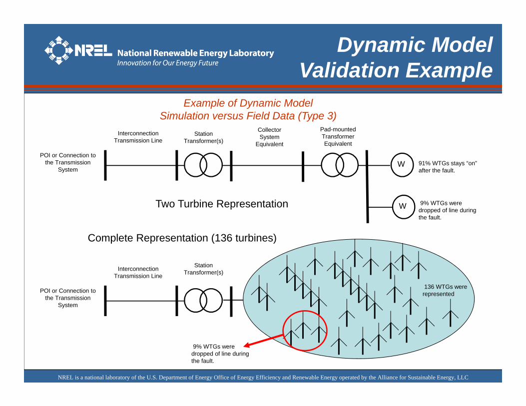
Dynamic ModelValidation Example
Example of Dynamic ModelSimulation versus Field Data (Type 3)
W
Pad-mounted Transformer Equivalent
91% WTGs stays “on” after the fault.
Collector System
Equivalent
Interconnection Transmission Line
POI or Connection to the Transmission
System
Station Transformer(s)
W 9% WTGs were dropped of line during the fault.
Two Turbine Representation
Interconnection Transmission Line
POI or Connection to the Transmission
System
Station Transformer(s)
136 WTGs were represented
9% WTGs were dropped of line during the fault.
Complete Representation (136 turbines)
NREL is a national laboratory of the U.S. Department of Energy Office of Energy Efficiency and Renewable Energy operated by the Alliance for Sustainable Energy, LLC
Dynamic ModelValidation Example
V and f
0.2
0.4
0.6
0.8
1
1.2
0 0.5 1 1.5 2Time (s)
Volta
ge (p
.u.)
0.95
0.99
1.03
1.07
1.11
1.15
Freq
uenc
y (p
.u.)
Vf
Real Power Comparison
0
20
40
60
80
100
120
140
0 0.5 1 1.5 2 2.5 3 3.5 4Time (s)
Rea
l Pow
er (M
W)
P-sim-1wtg (MW)P-measured (MW)P-sim-136WTG
Reactive Power Comparison
-60
-40
-20
0
20
40
60
80
0 0.5 1 1.5 2 2.5 3 3.5 4
Time (s)
Rea
ctiv
e Po
wer
(MVA
R)
Q-sim-1wtg (MVAR)Q-measured (MVAR)Q-sim-136WTG
WWind TurbineGeneratorEquivalent
InputV and f
A C BSystem Generator
Compare P&Q measured to P&Q simulatedV and f
Regulated Bus
NREL is a national laboratory of the U.S. Department of Energy Office of Energy Efficiency and Renewable Energy operated by the Alliance for Sustainable Energy, LLC
Dynamic ModelValidation
•Another method to validate new model is to use another model that has been validated against field measurement as a benchmark model.
•Several transient fault scenarios can be performed using both models, and the results can be compared.
•Parameter Tuning– The new model and the benchmark model may have some differences in
implementation, we may have to perform parameter tuning to match the output of the benchmark model.
– However, one should realize that the model may not be able to match the output of the benchmark model in all transient events.
•Parameter Sensitivity– In order to limit the number of parameters that should be tuned, parameter
sensitivity analysis may need to be performed.– In general important parameters are varied one by one and the sensitive
parameters can be tuned to match the bench mark model.
Comparison against other model (Benchmarking)
NREL is a national laboratory of the U.S. Department of Energy Office of Energy Efficiency and Renewable Energy operated by the Alliance for Sustainable Energy, LLC
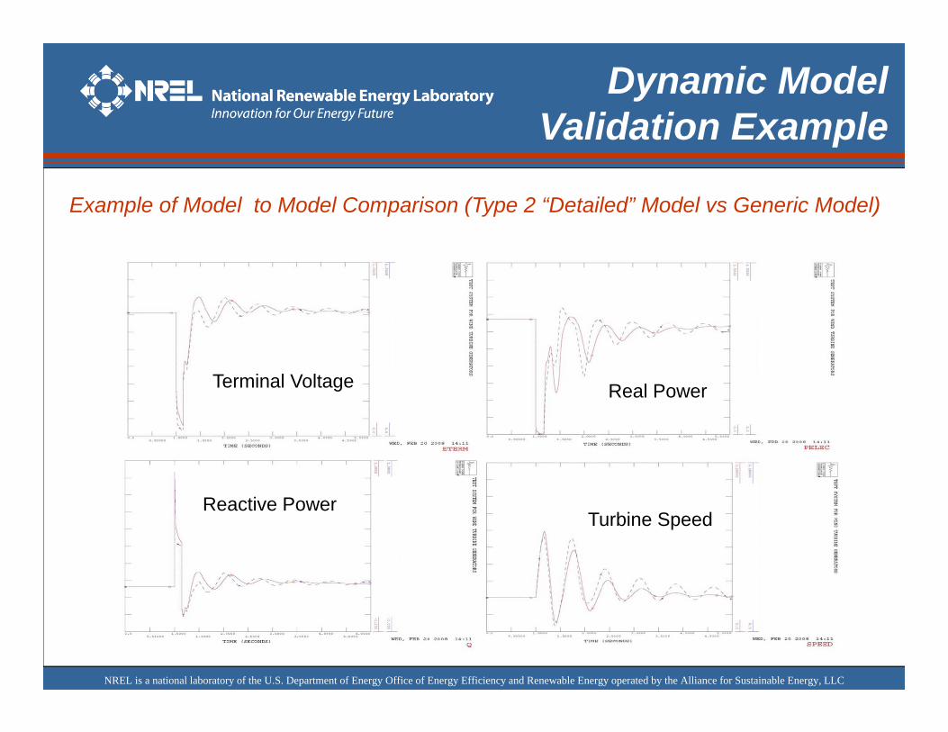
Dynamic ModelValidation Example
Terminal Voltage Real Power
Reactive PowerTurbine Speed
Example of Model to Model Comparison (Type 2 “Detailed” Model vs Generic Model)
NREL is a national laboratory of the U.S. Department of Energy Office of Energy Efficiency and Renewable Energy operated by the Alliance for Sustainable Energy, LLC