338
Wind River Network Stack for VxWorks 6 PROGRAMMER'S GUIDE Volume 3: Interfaces and Drivers ® 6.6 ® Wind River Network Stack for VxWorks 6 Programmer's Guide, 6.6

Wind RiverNetwork Stackfor VxWorks 6
PROGRAMMER'S GUIDEVolume 3: Interfaces and Drivers
®
6.6
®
Wind River Network Stack for VxWorks 6 Programmer's Guide, 6.6

Copyright © 2007 Wind River Systems, Inc.
All rights reserved. No part of this publication may be reproduced or transmitted in any form or by any means without the prior written permission of Wind River Systems, Inc.
Wind River, Tornado, and VxWorks are registered trademarks of Wind River Systems, Inc. The Wind River logo is a trademark of Wind River Systems, Inc. Any third-party trademarks referenced are the property of their respective owners. For further information regarding Wind River trademarks, please see:
http://www.windriver.com/company/terms/trademark.html
This product may include software licensed to Wind River by third parties. Relevant notices (if any) are provided in your product installation at the following location: installDir/productName/3rd_party_licensor_notice.pdf.
Wind River may refer to third-party documentation by listing publications or providing links to third-party Web sites for informational purposes. Wind River accepts no responsibility for the information provided in such third-party documentation.
Corporate HeadquartersWind River Systems, Inc.500 Wind River WayAlameda, CA 94501-1153U.S.A.
toll free (U.S.): (800) 545-WINDtelephone: (510) 748-4100facsimile: (510) 749-2010
For additional contact information, please visit the Wind River URL:
http://www.windriver.com
For information on how to contact Customer Support, please visit the following URL:
http://www.windriver.com/support
Wind River Network Stack for VxWorks 6 Programmer's Guide, 6.6
12 Nov 07 Part #: DOC-16137-ND-00

iii
Contents
1 Overview ............................................................................................... 1
1.1 Introduction ............................................................................................................. 1
1.2 About This Manual ................................................................................................ 2
1.2.1 About the IP Addresses Used in This Manual ..................................... 4
1.3 Additional Documentation .................................................................................. 4
Wind River Documentation .................................................................... 4Online Resources ...................................................................................... 5Books .......................................................................................................... 5
2 Configuring and Managing Memory ................................................... 7
2.1 Introduction ............................................................................................................. 7
2.2 Configuring Packet Buffer Pools ........................................................................ 8
2.2.1 Socket Priority ........................................................................................... 10
2.3 netBufLib Buffer Pools ......................................................................................... 12
2.3.1 Tuples ......................................................................................................... 13
2.3.2 Creating netBufLib Pools ........................................................................ 16
netPoolCreate( ) ........................................................................................ 17netPoolInit( ) ............................................................................................. 21

Wind River Network Stack for VxWorks 6Programmer's Guide, 6.6
iv
Memory Requirements Routines ........................................................... 24
2.4 Legacy Network Stack Pools ................................................................................ 25
3 Working with Drivers and Interfaces ................................................. 29
3.1 Introduction ............................................................................................................. 29
3.2 Overview of the MUX ............................................................................................ 30
3.3 Working with Network Driver Instances .......................................................... 32
3.3.1 Attaching a Service to a Network Interface .......................................... 33
3.3.2 Configuring a Network Interface with an Address ............................ 34
Using ifconfig( ) ........................................................................................ 35Retrieving Interface Information with ifconfig( ) ................................ 38Configuring an Interface with ifconfig( ) .............................................. 38Creating a Pseudo-Interface with ifconfig( ) ........................................ 40
3.3.3 Editing the Route Table ........................................................................... 40
3.3.4 Using routec( ) to Add or Delete Route Table Entries ........................ 41
3.3.5 Fixing Interfaces That Have Erroneous Addresses ............................. 42
3.3.6 Assigning a Host Name to an Address ................................................. 43
3.3.7 Bringing the Device Up for Protocol Communication ....................... 43
3.3.8 Configuring Router Advertisement and Solicitation for an Interface 44
Router Advertisement ............................................................................. 44Router Solicitation .................................................................................... 46
3.4 Adding Automatic IPv4 Interface Configuration ............................................ 47
Configuring VxWorks for Auto IP ........................................................ 47Configuring Auto IP ................................................................................ 48Using Auto IP ........................................................................................... 50
3.5 Using the Reverse ARP Client ............................................................................. 51
3.6 Working with IPv4 and IPv6 Tunneling ............................................................ 51
3.6.1 Configuring VxWorks for Tunneling .................................................... 52
GIF Tunnel Interface Driver ................................................................... 52
Contents
v
GRE Tunnel Interface Driver .................................................................. 536over4 Tunnel Interface Driver .............................................................. 536to4 Tunnel Interface Driver .................................................................. 54SIT Tunnel Interface Driver .................................................................... 54
3.6.2 Creating 6to4 Tunnels for IPv6 Packets ................................................ 55
3.6.3 Creating RFC 2893-Style Configured Tunnels ..................................... 56
3.6.4 An Example Tunnel ................................................................................. 58
3.7 Using the Shared-Memory Network .................................................................. 63
3.7.1 The Backplane Shared-Memory Region ............................................... 64
Backplane Processor Numbers ............................................................... 64The Shared-Memory Network Master .................................................. 65The Shared-Memory Anchor .................................................................. 66The Shared-Memory Heartbeat ............................................................. 67Shared-Memory Location ....................................................................... 67Shared Memory Size ................................................................................ 68Test-and-Set to Shared Memory ............................................................ 68
3.7.2 Interprocessor Interrupts ........................................................................ 69
3.7.3 Sequential Addressing ............................................................................. 71
3.7.4 Shared-Memory Network Configuration ............................................. 73
Example Configuration ........................................................................... 73Troubleshooting ....................................................................................... 79
4 Integrating a New Network Interface Driver ....................................... 81
4.1 Introduction ............................................................................................................. 82
4.1.1 How ENDs and NPT Drivers Differ ...................................................... 82
4.2 Configuring VxWorks for Network Interface Drivers .................................... 86
4.3 How VxWorks Launches and Uses Your Driver .............................................. 87
4.3.1 The Service-to-MUX Interface ................................................................ 87
4.3.2 The Data-Link-to-MUX Interface ........................................................... 89
4.3.3 Polled Mode – For Debugging Only ..................................................... 92
4.4 Driver Components ................................................................................................ 93
Wind River Network Stack for VxWorks 6Programmer's Guide, 6.6
vi
4.5 Transmitting Data .................................................................................................. 95
4.5.1 Transmit-complete Handler Interlocking Flag .................................... 95
4.5.2 Supporting Scatter-Gather Transmission ............................................. 96
4.5.3 Transmit Descriptor Clean-up ................................................................ 98
4.5.4 Transmit Descriptor Indexing ................................................................ 100
4.5.5 Transmit Packet Association List ........................................................... 101
4.5.6 Transmit-complete Handler ................................................................... 102
4.5.7 Transmit Descriptor Clean ...................................................................... 102
4.6 Implementing Checksum Offloading ................................................................ 102
4.6.1 Checksum Offloading and Receiving .................................................... 104
4.6.2 Checksum Offloading and Transmission ............................................. 106
4.7 Implementing a Network Driver ......................................................................... 108
4.7.1 Adding a Network Driver ....................................................................... 109
4.7.2 Launching the Driver ............................................................................... 117
4.7.3 Responding to Network Service Bind Calls ......................................... 117
4.7.4 Responding to Interrupts ........................................................................ 118
4.8 The Driver Interface with the MUX .................................................................... 128
4.9 Porting a BSD Driver to the MUX ....................................................................... 159
Remove Unit Number References ......................................................... 159Create an END Object to Represent the Device ................................... 160Implement the Standard END or NPT Entry Points ........................... 160
4.10 Managing Memory for Network Drivers and Services .................................. 162
4.10.1 Receive and Transmit Descriptor Issues ............................................... 163
Network Buffer Pools .............................................................................. 165
4.11 Collecting and Reporting Packet Statistics ....................................................... 175
4.11.1 Calling the Driver Routines .................................................................... 176

Contents
vii
5 Integrating a New Network Service .................................................... 179
5.1 Introduction ............................................................................................................. 179
5.2 Implementing the MUX/Network Service Interface ....................................... 180
5.2.1 Initializing the Interface .......................................................................... 180
5.2.2 Using MUX/Service Interface Routines ............................................... 184
Sending Packets ........................................................................................ 184Device Control .......................................................................................... 185Shutting Down an Interface .................................................................... 185
5.3 Interfacing with the MUX ..................................................................................... 186
5.3.1 Service Routines Registered Using mux[Tk]Bind( ) ............................ 186
5.4 Adding a Socket Interface to Your Service ........................................................ 191
5.4.1 Process Overview ..................................................................................... 192
5.4.2 Registering a Socket Back End ............................................................... 193
The Socket Functional Interface ............................................................. 195
5.4.3 Memory Validation and Socket Ioctls ................................................... 199
6 Working with the 802.1Q VLAN Tag .................................................. 201
6.1 Introduction ............................................................................................................ 201
6.2 Adding VLAN Support ......................................................................................... 202
6.3 About the 802.1Q VLAN Tag Header ................................................................. 203
6.4 MUX Extensions for Layer 2 VLAN Support .................................................... 204
6.4.1 Enabling VLAN Support for a Port ....................................................... 205
6.4.2 Disabling VLAN Support for a Port ...................................................... 207
6.4.3 MUX-L2 Ingress Rules ............................................................................. 207
6.4.4 MUX-L2 Egress Rules .............................................................................. 209
6.4.5 Accessing the MUX L2 Control Routines ............................................. 210
6.5 Current MUX-L2 Limitations ............................................................................... 211
Wind River Network Stack for VxWorks 6Programmer's Guide, 6.6
viii
6.6 VLAN Management ............................................................................................... 211
6.6.1 MUX-L2 VLAN Management ................................................................ 212
6.6.2 Subnet-Based VLAN Management ........................................................ 213
Consequences of Changing the VID ...................................................... 214Example of Subnet-Based VLAN Management ................................... 214
6.6.3 Socket-Based VLAN Management ........................................................ 216
6.7 Using the MUX-L2 Show Routines ..................................................................... 219
7 Quality of Service ................................................................................. 223
7.1 Introduction ............................................................................................................. 223
7.2 Differentiated Services .......................................................................................... 224
7.2.1 Including DiffServ in a Build .................................................................. 224
7.2.2 Using DiffServ .......................................................................................... 225
Adding a Filter Rule for a Meter/Marker Entity ................................. 225Deleting a Filter Rule from a Meter/Marker Entity ............................ 226Creating a Meter/Marker Entity ............................................................ 227Deleting a Meter/Marker Entity ............................................................ 227Mapping a Filter to a Meter/Marker Entity ......................................... 227Removing a Filter-to-Meter/Marker Entity Mapping ........................ 228
7.2.3 Classes ........................................................................................................ 228
7.2.4 Creating New Meter/Marker Entity Varieties .................................... 232
7.2.5 Using Existing Meter/Marker Entity Varieties ................................... 234
SimpleMarker ........................................................................................... 234Single-Rate Three-Color Marker ............................................................ 235
7.3 Network Interface Output Queues ..................................................................... 237
7.3.1 Operations ................................................................................................. 240
Adding an Interface Output Queue ...................................................... 240Getting an Object that Describes an Interface Output Queue ........... 241Adding a Filter Rule to a Container Queue .......................................... 241Deleting a Filter Rule from a Container Queue ................................... 242
7.3.2 Leaf Queues ............................................................................................... 242
Contents
ix
7.3.3 Container Queues ..................................................................................... 247
Available Container Queues ................................................................... 249
7.3.4 Adding a New Queue Type .................................................................... 252
8 Ingress Traffic Prioritization ............................................................... 257
8.1 Introduction ............................................................................................................. 257
8.2 Factors to Consider Before Using Ingress Filtering ......................................... 258
Systems with Multiple Interfaces for Incoming Traffic ...................... 259Traffic Congestion and Fairness ............................................................ 259Driver Variety ........................................................................................... 259
8.3 Building VxWorks to Include Ingress Traffic Prioritization ......................... 260
8.4 Implementing an Ingress Filter Routine ........................................................... 261
8.4.1 Registering an Ingress Filter Routine .................................................... 262
A MUX Routines and Data Structures .................................................... 263
A.1 Introduction ............................................................................................................. 263
A.2 MUX Routines ......................................................................................................... 263
A.2.1 endFindByName( ) ................................................................................... 265
A.2.2 muxAddressForm( ) ................................................................................. 266
A.2.3 muxLinkHeaderCreate( ) ........................................................................ 267
A.2.4 muxDevExists( ) ....................................................................................... 267
A.2.5 muxDevLoad( ) ......................................................................................... 268
A.2.6 muxDevStart( ) ......................................................................................... 268
A.2.7 muxDevStop( ) .......................................................................................... 269
A.2.8 muxDevUnload( ) .................................................................................... 269
A.2.9 muxError( ) ................................................................................................ 270
A.2.10 muxIfFuncAdd( ) ...................................................................................... 270
A.2.11 muxIfFuncDel( ) ....................................................................................... 271

Wind River Network Stack for VxWorks 6Programmer's Guide, 6.6
x
A.2.12 muxIfFuncGet( ) ....................................................................................... 271
A.2.13 muxIoctl( ) ................................................................................................. 272
A.2.14 muxMCastAddrAdd( ) ............................................................................ 272
A.2.15 muxMCastAddrDel( ) .............................................................................. 273
A.2.16 muxMCastAddrGet( ) .............................................................................. 273
A.2.17 muxPacketAddrGet( ) .............................................................................. 274
A.2.18 muxPacketDataGet( ) ............................................................................... 274
A.2.19 muxShow( ) ............................................................................................... 275
A.2.20 muxTkBind( ) ............................................................................................ 275
A.2.21 muxBind( ) ................................................................................................. 277
A.2.22 muxTkCookieGet( ) .................................................................................. 279
A.2.23 muxTkDrvCheck( ) .................................................................................. 279
A.2.24 muxTkPollReceive( ) ................................................................................ 280
A.2.25 muxTkPollSend( ) ..................................................................................... 281
A.2.26 muxReceive( ) ........................................................................................... 281
A.2.27 muxTkReceive( ) ....................................................................................... 282
A.2.28 muxSend( ) ................................................................................................ 283
A.2.29 muxTkSend( ) ............................................................................................ 284
A.2.30 muxTxRestart( ) ........................................................................................ 285
A.2.31 muxUnbind( ) ............................................................................................ 285
A.2.32 muxAddrResFuncAdd( ) ......................................................................... 286
A.2.33 muxAddrResFuncDel( ) .......................................................................... 286
A.2.34 muxAddrResFuncGet( ) .......................................................................... 287
A.3 Data Structures ........................................................................................................ 287
A.3.1 CL_BLK ...................................................................................................... 288
A.3.2 DEV_OBJ ................................................................................................... 289
A.3.3 DRV_CTRL ................................................................................................ 290
A.3.4 END_CAPABILITIES ............................................................................... 290
Contents
xi
A.3.5 END_ERR .................................................................................................. 293
A.3.6 END_MEDIA ............................................................................................ 296
A.3.7 END_MEDIALIST .................................................................................... 297
A.3.8 END_OBJ ................................................................................................... 297
A.3.9 END_RCVJOBQ_INFO ........................................................................... 301
A.3.10 END_QUERY ............................................................................................ 301
A.3.11 LL_HDR_INFO ......................................................................................... 302
A.3.12 M_BLK ....................................................................................................... 302
A.3.13 M_BLK_HDR ............................................................................................ 304
A.3.14 M_LINK ..................................................................................................... 305
A.3.15 M_PKT_HDR ............................................................................................ 306
A.3.16 MULTI_TABLE ......................................................................................... 307
A.3.17 NET_FUNCS ............................................................................................. 308
Index .............................................................................................................. 309

Wind River Network Stack for VxWorks 6Programmer's Guide, 6.6
xii
1
1Overview
1.1 Introduction 1
1.2 About This Manual 2
1.3 Additional Documentation 4
1.1 Introduction
The Wind River Network Stack is a dual IPv4/IPv6 TCP/IP stack that is designed for use in modern, embedded real-time systems. It includes many services and protocols that you can use to build networking applications.
This is the third volume of the Wind River Network Stack Programmer's Guide. For information on the following topics, see the Overview chapter of the Wind River Network Stack Programmer's Guide, Volume 1:
■ an overview of the Wind River Network Stack■ a list of features unique to Wind River platforms■ a guide to relevant additional documentation■ where to get the latest release information
Wind River Network Stack for VxWorks 6Programmer's Guide, Volume 3: Interfaces and Drivers, 6.6
2
1.2 About This Manual
The following is an overview of the information you will find in this manual. See 1.3 Additional Documentation, p.4 to learn about the other two volumes that describe the Wind River Network Stack, and additional documentation that you may find helpful.
1. Overview
This chapter.
2. Configuring and Managing Memory
This chapter describes the following:
■ Configuring packet buffer pools used by the network stack (2.2 Configuring Packet Buffer Pools, p.8).
■ Creating and using netBufLib pools (2.3 netBufLib Buffer Pools, p.12).
■ The legacy network stack data pool and network stack system pool, used by previous versions of the network stack and sometimes still required by particular applications (2.4 Legacy Network Stack Pools, p.25).
3. Working with Drivers and Interfaces
In addition to drivers supplied for physical network interfaces, the Wind River Network Stack also includes drivers for the creation of GIF, GRE, SIT, 6to4, and 6over4 devices—over IPv4, IPv6, or both. This chapter provides instructions and some background information on how to create and configure device instances associated with the network stack. This includes the following:
■ network interface instances for communication with the local network■ router advertisement and solicitation■ using RARP (reverse ARP)■ tunneling over IPv4 or IPv6
4. Integrating a New Network Interface Driver
This chapter describes how to integrate a new network interface driver with Wind River Network Stack. For this, use the MUX, which is an interface that
NOTE: The tunneling feature is available only in the Wind River Platforms builds of the network stack. The Wind River General Purpose Platform, VxWorks Edition, does not support tunneling.

1 Overview1.2 About This Manual
3
1insulates network services from the particulars of network interface drivers, and vice versa.
If you want to use a driver based on the BSD 4.3 or 4.4 models, you must port it to the MUX interface model, as described in this chapter.
5. Integrating a New Network Service
A network service is an implementation of the network and transport layers of the OSI network model. Under the Wind River Network Stack, network services communicate with the data link layer through the MUX interface.This chapter describes how to integrate a new network service with the MUX and, thus, with the network stack.
6. Working with the 802.1Q VLAN Tag
This chapter describes the implementation of 802.1Q VLAN tagging for VxWorks and tells you how to configure VxWorks to include this feature.
7. Quality of Service and 8. Ingress Traffic Prioritization
These chapters describe the network stack’s Quality of Service (QoS) capability, in which the stack treats some network traffic to better service than others. The Wind River Network Stack implements the Differentiated Services (DiffServ) model of QoS, which classifies traffic entering a network and conditionalizes it before treating it in an appropriate manner. Similarly, the ingress traffic prioritization feature allows you to assign priorities to the packets arriving at an interface and have the stack process higher-priority packets before lower-priority packets.
NOTE: The 802.1Q VLAN tagging feature is available only in the Wind River Platforms builds of the network stack. The Wind River General Purpose Platform, VxWorks Edition, does not support 802.1Q VLAN tagging.
NOTE: The QoS feature is available only in the Wind River Platforms builds of the network stack. The Wind River General Purpose Platform, VxWorks Edition, does not support QoS.
The Wind River Network Stack does not support ingress filtering in symmetric multiprocessing (SMP) builds.

Wind River Network Stack for VxWorks 6Programmer's Guide, Volume 3: Interfaces and Drivers, 6.6
4
A. MUX Routines and Data Structures
This appendix describes the routines and data structures that comprise the MUX interface.
1.2.1 About the IP Addresses Used in This Manual
When working with the examples in this manual, you may find it convenient to cut and paste example text into source code or to a command line. To avoid disrupting the use of IPv4 or IPv6 addresses that are, or might be, put into service, the examples in this manual restrict themselves to the following address spaces:
■ 10/24 – one part of the private address space■ 127.0/8 – loopback addresses■ 169.254/16 – link local addresses■ 172.16/12 – another part of the private address space■ 192.0.2/24 – test and documentation addresses■ 192.168/16 – another part of the private address space■ 2001:DB8::/32 – test and documentation addresses (RFC 2849)■ FE80::/10 – link local addresses
1.3 Additional Documentation
The following sections describe additional documentation about the technologies described in this book.
Wind River Documentation
The Wind River Network Stack is described in the three volumes of the Wind River Network Stack Programmer’s Guide:
■ Volume 1 has an overview with general information about the network stack, and describes the Network and Transport layers.
■ Volume 2 describes application-layer protocols and socket programming.
■ Volume 3 (this volume) describes network services, drivers, and the MUX, which is an abstraction layer between drivers and services.

1 Overview1.3 Additional Documentation
5
1The Getting Started guide for your Platform includes instructions on how to build a component or product into VxWorks, either through the Workbench Kernel Editor or the vxprj utility.
For information on using Workbench to create a VxWorks Image Project and to include build components, see the Wind River Workbench User’s Guide for VxWorks. For information on using the vxprj command-line utility, see the VxWorks Command-Line Tools User’s Guide.
The Wind River Platforms for VxWorks Migration Guide details how to migrate from an earlier release of the network stack.
For information on boot devices and host-side network diagnostic tools, see the Tornado User’s Guide: Getting Started.
Online Resources
Online resources are as follows:
■ The Internet Engineering Task Force, http://www.ietf.org
Books
Additional documentation is as follows:
■ Internetworking with TCP/IP, Volume I: Principles, Protocols, and Architecture, Douglas E. Comer.
■ UNIX Network Programming, Volume 2, Second Edition by W. Richard Stevens

Wind River Network Stack for VxWorks 6Programmer's Guide, Volume 3: Interfaces and Drivers, 6.6
6

7
2Configuring and
Managing Memory
2.1 Introduction 7
2.2 Configuring Packet Buffer Pools 8
2.3 netBufLib Buffer Pools 12
2.4 Legacy Network Stack Pools 25
2.1 Introduction
The Wind River Network Stack and the network drivers that work with it use several varieties of memory pool for their memory allocation needs:
■ The stack allocates control structures, such as sockets, route entries, and the like, directly out of the system heap.
■ The stack allocates buffers to hold packet data (particularly for transmission) out of one or more buffer pools. The stack also allocates, initializes, and maintains per-packet packet header control structures. It joins one of these structures with a buffer pool when a packet is allocated, and divorces the structure from the buffer (making each available for a new packet) when a packet is freed.
■ VxWorks network device drivers use netBufLib pools to allocate buffers into which they receive packets. Drivers create these pools when the MUX loads a

Wind River Network Stack for VxWorks 6Programmer's Guide, Volume 3: Interfaces and Drivers, 6.6
8
network interface (usually at initialization time). Other protocols, such as TIPC, also make use of netBufLib pools.
This chapter describes the following:
■ How to configure packet buffer pools used by the network stack (2.2 Configuring Packet Buffer Pools, p.8).
■ How to create and use netBufLib pools (2.3 netBufLib Buffer Pools, p.12).
■ How to configure the legacy network stack data pool and network stack system pool, used by previous versions of the network stack and still required by some applications (2.4 Legacy Network Stack Pools, p.25).
2.2 Configuring Packet Buffer Pools
The network stack gets its packet-related memory from several buffer pools of varying buffer sizes and allocation priorities. The stack allows an arbitrary number of pools, but in practice you will need a small number. With the kernel configuration mechanism you can specify up to 11 different pools.
In Workbench’s VxWorks kernel configuration editor, the component IPNet packet pool support (INCLUDE_IPNET_USE_PACKET_POOL) enables general packet pool support, and you can use the IPNet packet pool configurations (SELECT_IPNET_PACKET_POOL) parameter to choose which packet pools are included. To configure these pools, select one or more of the INCLUDE_IPNET_PACKET_POOL_n pools (where n ranges from 1 to 11) for inclusion in the image, and configure the parameters of each desired pool. Each pool has three parameters that you can adjust:
MIN_PRIO_POOL_n (Minimum priority level for SIZE_POOL_n packet pool) This specifies the allocation priority for the pool, which is the minimum allocation priority that a caller can have in order for it to allocate packet buffers from this pool. The priority ranges from a minimum of 0 (IPCOM_PKT_MPRIO_MIN) to a maximum of 10 (IPCOM_PKT_MPRIO_MAX).
When choosing a pool’s minimum allocation priority, be aware that most protocol packet buffer allocation occurs at priority IPCOM_PKT_MPRIO_STACK (==IPCOM_PKT_MPRIO_MAX), while buffer allocation on behalf of socket applications normally occurs at priority IPCOM_PKT_MPRIO_DEFAULT (==IPCOM_PKT_MPRIO_MIN+1). The values

2 Configuring and Managing Memory2.2 Configuring Packet Buffer Pools
9
2
of the IPCOM_PKT_MPRIO_* macros are defined in the header file ipcom/include/ipcom_pkt.h; if you change these values you must rebuild the network stack as well as the VxWorks image.
Wind River recommends that you create at least one pool at the maximum priority level (IPCOM_PKT_MPRIO_MAX). This ensures that TCP can always allocate pure ACK packets (which it allocates while at a priority equal to IPCOM_PKT_PRIO_STACK). Such a pool can be small: it can contain few packets (around 10 or so) at a size of between 200 and 500 bytes per packet.
If you omit such a pool, this can lead to a scenario like the following: The stack sends data through many TCP sockets—so many that the stack allocates all available packets and places them in the TCP retransmission queue, at which point it is no longer able to send an ACK if it receives a new TCP packet (carrying data). If you were to include a high-priority pool, the stack would be able to send an ACK in such a circumstance.
TCP sessions that simultaneously send bulk data in both directions may need to allocate a packet of full MTU size, and may include data together with an ACK rather than sending a pure ACK. For this reason, you need to be able to allocate MTU-sized packets for at least the largest MTU in the system, and there should be at least a small number of packets of this size available at the IPCOM_PKT_MPRIO_STACK priority level.
NUM_POOL_n (Number of SIZE_POOL_n packet pool) The number of packet buffers in this pool. An equal number of packet headers (see below) is added for general use.
SIZE_POOL_n (Size of packet pool (in bytes)) The size, in bytes, of each packet buffer in the pool.
This is the MTU (maximum transmission unit) of the largest packet that fits in this buffer. This packet size includes the network and transport layer envelopes, but does not include space reserved for the link-level header.
The network stack always uses contiguous buffers to store datagrams that it sends; it does not chain together segments for a single packet. This means that if your application needs to send datagrams of size 30,000 (including the IP header but not the link header), you must configure a packet pool with SIZE_POOL_n of at least 30,000 bytes, even though the protocol layer of the stack will fragment such datagrams for most link types.
The stack will align the start of a datagram (the IP header) to a 32-bit boundary when it copies data into the buffer. When you allocate a packet with ipcom_pkt_malloc( ) that routine ensures that the buffer address and real length are rounded up to the next cache line size (so you do not need to

Wind River Network Stack for VxWorks 6Programmer's Guide, Volume 3: Interfaces and Drivers, 6.6
10
increase SIZE_POOL_n to accommodate such rounding). The stack uses the value of the configuration parameter IPNET_CACHE_BUFSIZE (of the component INCLUDE_IPNET) as the cache line size. If the value of this parameter is zero, the stack instead uses the value of _CACHE_ALIGN_SIZE as the cache line size value.
You can allocate additional packet header structures by specifying a packet pool with SIZE_POOL_n equal to zero, and NUM_POOL_n equal to the number of packet headers you want to add.
The stack allocates the memory for these packet buffers from the system heap at initialization time. The default pools and their parameters are sufficient only for systems with very modest networking requirements; you must increase the numbers and perhaps add pools of larger sizes if your application uses the network more intensively.
2.2.1 Socket Priority
The socket priority determines from which part of the packet pool the socket user can allocate packets. A socket can allocate a packet from a pool only if the socket priority is equal to or higher than the priority of packet pool.
Control socket priority with the socket option IP_SO_X_PKT_MPRIO, which is relevant to the IP_SOL_SOCKET socket option level. Set this priority between IPCOM_PKT_MPRIO_MIN and IPCOM_PKT_MPRIO_MAX, inclusive.
By default, when you create a socket it has priority IPCOM_PKT_MPRIO_DEFAULT that, by default, is equal to IPCOM_PKT_MPRIO_MIN.
Drivers allocate packets with priority IPCOM_PKT_MPRIO_DRV, which defaults to IPCOM_PKT_MPRIO_MAX. A driver that receives TCP or other reliable protocols should allocate packets with a high priority so that it will not be prevented from receiving ACK segments when low priority buffers are unavailable. When the stack receives an ACK segment it can usually remove packets from its resend queue and return them to the pool.
IPCOM_PKT_MPRIO_STACK defaults to IPNET_PKT_MPRIO_MAX. The network stack uses this constant as the priority when it allocates ARP, ICMP, and ICMPv6 packets in response to incoming traffic.

2 Configuring and Managing Memory2.2 Configuring Packet Buffer Pools
11
2
An example configuration of the ipnet packet pool is found in installDir/components/ip_net2-6.n/osconfig/vxworks/src/ipnet//ipnet_config.c. The following example is similar to what you would find there:
IP_CONST Ipnet_conf_pkt_pool ipnet_conf_pkt_pool[ ] ={{ 65, 1500, IPCOM_PKT_MPRIO_MIN },{ 10, 1500, IPCOM_PKT_MPRIO_MAX },{ 8, 10000, IPCOM_PKT_MPRIO_MIN },{ 2, 10000, IPCOM_PKT_MPRIO_MAX },{ 0, 0 } /* End marker */};
In this example, this pool has two varieties of packet that any application can allocate: 65 packets with MTU 1500 and 8 with MTU 10000. There are also two varieties of packet that only applications with the highest priority can allocate: 10 packets with MTU 1500 and 2 with MTU 10000.
A socket-using application that calls a socket routine like sendmsg( ) or connect( ) allocates a packet from the first group in this list for which the socket has a sufficient priority. The stack orders the packet pool so that applications allocate low-priority packets before high-priority packets.
Applications that use sockets with the maximum priority can continue sending and receiving data even when all low-priority packets are allocated, but all other applications will be unable to allocate packets until low-priority packets are returned to the pool.
When an application attempts to allocate a packet, but no free packet of sufficient size exists, the attempt will block unless the application explicitly passes a non-blocking flag to ipcom_pkt_malloc( ).
You must determine the number of packets at each priority level based on your system requirements. A good rule of thumb is to have more packets at low priority, since both low- and high-priority sockets can use those.
! WARNING: The version of ipnet_config.c that is actually effective for VxWorks is installDir/components/ip_net2-6.n/osconfig/vxworks/src/ipnet/ipnet_config.c (changing the file with the same name in installDir/components/ip_net2-6.n/ipnet2/config/ will not affect the configuration of standard VxWorks image builds).
The ipnet_conf_pkt_pool[ ] array defined in this file contains entries defined in terms of the configuration parameters NUM_POOL_n, SIZE_POOL_n, and MIN_PRIO_POOL_n of the INCLUDE_IPNET_PACKET_POOL_n components. However, the meaning of the pool entries is the same as in the above simpler example, which we will refer to here for illustrative purposes.

Wind River Network Stack for VxWorks 6Programmer's Guide, Volume 3: Interfaces and Drivers, 6.6
12
2.3 netBufLib Buffer Pools
The upper layers of the VxWorks IP network stack do not use netBufLib buffer pools, but VxWorks network device drivers do, as does the TIPC protocol. If you modify or exchange data directly with VxWorks network device drivers, you may need to be familiar with the netBufLib library and its interfaces. You may also find this library useful if your application needs a flexible, standalone buffer management implementation.
The netBufLib library facilitates creation and management of pools of buffers (called clusters—see also 2.3.1 Tuples, p.13), along with the control structures—M_BLKs and CL_BLKs—that link clusters into chains and (in some cases) share clusters between different code paths. The netBufLib library presents a high-level interface that depends upon particular back-end implementations that allocate and free pool resources. There are three different netBufLib back ends presently implemented in the Wind River Network Stack:
netBufPoolThe default, and most full-featured pool implementation. It supports multiple cluster pools of different sizes, and allows you to allocate separate M_BLKs, CL_BLKs, and clusters, or to allocate all three together in coordinated tuples. To use this pool back end, include the INCLUDE_NETBUFPOOL component in your build.
linkBufPoolA pool implementation specialized to provide optimized allocation of tuples of a single cluster size. Wind River recommends that you use this back-end for a network device driver’s packet receive pools. This back end fuses together the M_BLK and CL_BLK control structures into a single contiguous M_LINK structure. You cannot allocate unattached clusters, M_BLKs, or CL_BLKs when you use linkBufPool (you may, however, create a linkBufPool without attached clusters and allocate M_LINK structures from it that are not attached to clusters.) To use this pool back end, include the INCLUDE_LINKBUFPOOL component in your build.
nullBufPool This pool back end is not for application use. It is only for internal use by the stack.
It is a single-purpose back end implementation that the stack uses when it passes packets to device drivers for them to transmit. Since the network device drivers expect packets to be described by M_BLK/CL_BLK/cluster tuples (see 2.3.1 Tuples, p.13, for more on tuples), but the stack does not use this format, the stack must “repackage” packets that it passes to the driver transmit routine

2 Configuring and Managing Memory2.3 netBufLib Buffer Pools
13
2
so that they appear as tuples. The stack does this efficiently by using the nullBufPool back end. (Some future network device drivers may expect the stack-native packet format, to avoid even the minimal overhead of the nullBufPool wrapping.)
To enable the netBufLib library, include the INCLUDE_NETBUFLIB component in your image. You can call display routines for netBufLib pools if you include the INCLUDE_NETPOOLSHOW component in your image. Some less-frequently-used routines in the netBufLib API are in a separate library, netBufAdvLib, to which you can gain access if you include the INCLUDE_NETBUFADVLIB component. The capabilities of this library are described briefly in the section on creating netBufLib pools, see 2.3.2 Creating netBufLib Pools, p.16 and the reference entry for netBufAdvLib for more information.
2.3.1 Tuples
The netBufLib API describes a packet by a tuple or by a chain of tuples. The tuple is a construct that consists of an M_BLK structure, a CL_BLK structure, and a cluster buffer.
■ The M_BLK is similar in nature to the mbuf used in the BSD network stack. Among other members, the M_BLK has a pClBlk field, which is a pointer to the CL_BLK. See A.3.12 M_BLK, p.302.
■ The CL_BLK in turn holds a pointer to the cluster buffer. The cluster buffer is the DMA buffer. The M_BLK also has a pointer into the cluster buffer but this pointer can be modified by software to add or subtract offsets. The cluster buffer pointer in the CL_BLK always points to the base of the cluster buffer. See A.3.1 CL_BLK, p.288.
■ The access path to the start address of a cluster buffer in a tuple is pMblk->pClBlk->clNode.pClBuf.
These structures are defined in the header file target/h/wrn/coreip/netBufLib.h and shown in Figure 2-1.

Wind River Network Stack for VxWorks 6Programmer's Guide, Volume 3: Interfaces and Drivers, 6.6
14
Figure 2-1 The Structures in a Tuple
struct mBlk
pClBuf
aux
(M_BLK)
struct clBlk(CL_BLK)
union clBlkList(CL_BLK_LIST)
struct mHdr(M_BLK_HDR)
struct pktHdr(M_PKT_HDR)
mNext
mNextPkt
char *pClBlkNext
clNode
pClBlk
struct netPool
pNetPool
mBlkPktHdr
mBlkHdr
struct clBlk(CL_BLK)
2 Configuring and Managing Memory2.3 netBufLib Buffer Pools
15
2
.
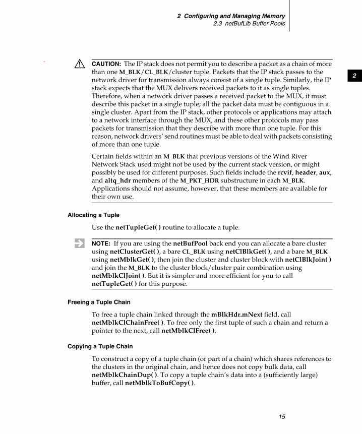
Allocating a Tuple
Use the netTupleGet( ) routine to allocate a tuple.
Freeing a Tuple Chain
To free a tuple chain linked through the mBlkHdr.mNext field, call netMblkClChainFree( ). To free only the first tuple of such a chain and return a pointer to the next, call netMblkClFree( ).
Copying a Tuple Chain
To construct a copy of a tuple chain (or part of a chain) which shares references to the clusters in the original chain, and hence does not copy bulk data, call netMblkChainDup( ). To copy a tuple chain’s data into a (sufficiently large) buffer, call netMblkToBufCopy( ).
! CAUTION: The IP stack does not permit you to describe a packet as a chain of more than one M_BLK/CL_BLK/cluster tuple. Packets that the IP stack passes to the network driver for transmission always consist of a single tuple. Similarly, the IP stack expects that the MUX delivers received packets to it as single tuples. Therefore, when a network driver passes a received packet to the MUX, it must describe this packet in a single tuple; all the packet data must be contiguous in a single cluster. Apart from the IP stack, other protocols or applications may attach to a network interface through the MUX, and these other protocols may pass packets for transmission that they describe with more than one tuple. For this reason, network drivers’ send routines must be able to deal with packets consisting of more than one tuple.
Certain fields within an M_BLK that previous versions of the Wind River Network Stack used might not be used by the current stack version, or might possibly be used for different purposes. Such fields include the rcvif, header, aux, and altq_hdr members of the M_PKT_HDR substructure in each M_BLK. Applications should not assume, however, that these members are available for their own use.
NOTE: If you are using the netBufPool back end you can allocate a bare cluster using netClusterGet( ), a bare CL_BLK using netClBlkGet( ), and a bare M_BLK using netMblkGet( ), then join the cluster and cluster block with netClBlkJoin( ) and join the M_BLK to the cluster block/cluster pair combination using netMblkClJoin( ). But it is simpler and more efficient for you to call netTupleGet( ) for this purpose.

Wind River Network Stack for VxWorks 6Programmer's Guide, Volume 3: Interfaces and Drivers, 6.6
16
There are various other routines available for manipulating, allocating, and freeing tuples or bare clusters, and control structures; see the netBufLib reference manual entry, or the source code at target/src/wrn/coreip/common/mem/netBufLib.c.
2.3.2 Creating netBufLib Pools
To create netBufLib pools, call either the older netPoolInit( ) routine or the newer netPoolCreate( ) routine. Wind River recommends that you call the netPoolCreate( ) routine, since it frees you from having to allocate memory for the clusters, CL_BLKs, and M_BLKs making up a netBufLib pool. Also, pools that you create by calling netPoolCreate( ) have the following additional capabilities that are not available in pools that you create by calling netPoolInit( ):
■ By calling netPoolRelease( ) you can safely free those pools that you created with netPoolCreate( ). This routine puts a pool into a release state; when all the holders of buffers belonging to the pool have returned them to the pool, the pool is freed. A driver can use this routine to free a network device’s receive pool when the device is unloaded.
■ By calling the netPoolIdGet( ) routine you can look up by name a pool that you created with netPoolCreate( ). You can obtain the name of such a pool by calling netPoolNameGet( ).
■ Several agents (network interfaces, protocols, and so forth) may share a pool that you create with netPoolCreate( ). An agent that wants to use such a pool may call netPoolAttach( ) to look up a pool by name and attach to it; this increments a count that prevents the pool from being released until all agents that have attached to it detach from it by calling netPoolDetach( ).
■ You can associate a set of attributes with pools that you create with netPoolCreate( )—including shareability, buffer alignment, and the memory partitions out of which the buffers and control structures that netPoolCreate( ) allocates at pool creation time (see The pNetBufCfg Parameter to netPoolCreate( ), p.18 ).
■ You can bind a pool that you create with netPoolCreate( ) to another pool, called its parent pool, by calling the netPoolBind( ) routine. When an agent attempts to allocate a packet from a pool, but that pool does not have sufficient resources, the attempt will repeat in the pool’s parent pool. When the agent later frees the packet, the packet is returned to whichever pool it was originally allocated from. A parent pool may be the parent of several child pools, and provides a shared back-up supply for the child pools, which are usually private to one agent. You cannot successfully release a parent pool while there

2 Configuring and Managing Memory2.3 netBufLib Buffer Pools
17
2
are still children bound to it; you must first unbind its child pools by calling netPoolUnbind( ). You must configure a parent pool to have the same pool attributes as any child pools that you attach to it, and each of these pools must be sharable (see attributes, p.19).
To enable the pool attachment, pool binding, and pool attributes capabilities, include the component INCLUDE_NETBUFADVLIB in your image. The netPoolRelease( ) capability, and pool look-up by name, are available for pools that you create with netPoolCreate( ) even if you do not include the INCLUDE_NETBUFADVLIB component.
Pools that you create with netPoolInit( ) lack the above capabilities. However, netPoolInit( ) allows (and requires) that you create a pool using pre-allocated memory for the clusters and control structures. If your code needs to create a pool in this manner, it should call the netPoolInit( ) routine rather than netPoolCreate( ).
netPoolCreate( )
To create a memory pool, call netPoolCreate( ):
NET_POOL_ID netPoolCreate(NETBUF_CFG * pNetBufCfg, /* Configuration Structure */POOL_FUNC * pFuncTbl /* Optional plug in function table */)
This routine takes two parameters:
■ pNetBufCfg, see The pNetBufCfg Parameter to netPoolCreate( ), p.18■ pFuncTbl, see The pFuncTbl Parameter to netPoolCreate( ), p.17
The pFuncTbl Parameter to netPoolCreate( )
The pFuncTbl parameter is a pointer to a table of function pointers that specifies which netBufLib back end implementation governs the new pool (see 2.3 netBufLib Buffer Pools, p.12). Set this parameter to one of the following values:
_pNetPoolFuncTblto use the netBufPool back end with a backward-compatible memory requirements routine that guarantees only four-byte alignment for both clusters and control structures
NULLto use the netBufPool back end with a memory requirements routine (_netMemReqDefault( ) in netBufLib.c) that yields more stringent alignment,

Wind River Network Stack for VxWorks 6Programmer's Guide, Volume 3: Interfaces and Drivers, 6.6
18
which may yield marginally better performance than the backwards-compatible memory requirements routine chosen when _pNetPoolFuncTbl is explicitly passed
_pLinkPoolFuncTblto use the linkBufPool back end
The pNetBufCfg Parameter to netPoolCreate( )
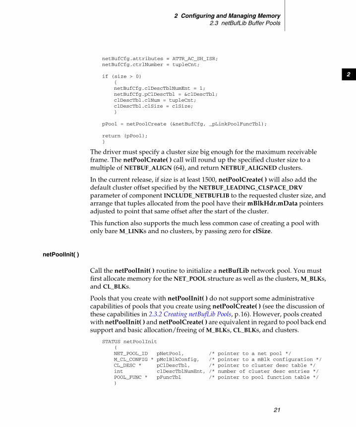
Pass netPoolCreate( ) a NETBUF_CFG structure that you have filled in to indicate what sort of pool you want to create (see Figure 2-2).
The members of this structure are as follows:
pName A string of length less than NET_POOL_NAME_SZ (this is 16 bytes for most architectures). netPoolCreate( ) copies this name into the NET_POOL structure that it returns.
pDomain and bMemExtraSize These members are ignored at present. Set them to NULL and 0 (zero) respectively.
Figure 2-2 The NETBUF_CFG Class
struct netBufCfg(NETBUF_CFG)
pName : char *
pClDescTbl
struct netBufClDesc(NETBUF_CL_DESC)
attributes : UINT32pDomain : void *ctrlNumber : intctrlPartId : PART_IDbMemExtraSize : intbMemPartId : PART_IDclDescTblNumber : int
clSize : intclNum : int
*
— pool name— pool attributes— RTP ID (or NULL for kernel)— # of control structures to allocate— memory partition for control structures (NULL == kernel)— extra memory for run-time buffers— memory partition for buffers (NULL == default for kernel or RTP)— number of entries in pClDescTbl
— cluster size— number of clusters in the pool

2 Configuring and Managing Memory2.3 netBufLib Buffer Pools
19
2
ctrlPartId and bMemPartId Set these to the memory partitions from which the pool is to allocate memory for control structures (M_BLKs and CL_BLKs) and for cluster buffers, respectively. Set these to NULL if you want to allocate this memory from the kernel system heap.
ctrlNumber Set this to the number of M_BLKs the pool allocates; the pool will allocate the same number of CL_BLKs as well.
attributes The pool’s nominal cluster alignment and whether the pool can be shared (see 2.3.2 Creating netBufLib Pools, p.16 for a discussion of pool sharing). Set this to one of the following values:
■ ATTR_AI_SH_ISR – integer-aligned; shareable■ ATTR_AC_SH_ISR – cache-line-aligned; shareable■ ATTR_AI_ISR – integer-aligned; private■ ATTR_AC_ISR – cache-line-aligned; private
The actual alignment of clusters is not actually controlled by the value of this member, but by the memory requirements routine provided either by the back end implementation, or (when _pFuncTbl is NULL) by netBufLib itself. See Memory Requirements Routines, p.24.
pClDescTbl Points to an array of clDescTblNumEnt NETBUF_CL_DESC structures with which you specify the number and (un-rounded) size of clusters in one of the cluster pools belonging to the NET_POOL that you are creating with netPoolCreate( ).
Note that the linkBufPool back end allows you to choose only a single cluster size (that is, clDescTblNumEnt is either 1 or 0; when 0, the pool provides only bare M_LINKs, and you have to attach your own clusters).
There are also cluster size limitations when you use the netBufPool back end:
■ The minimum cluster size is 16 bytes.
■ The maximum cluster size is 65536 bytes.
■ In a given pool, only one cluster size is allowed in each interval [2n, 2n+1) between successive powers of two.
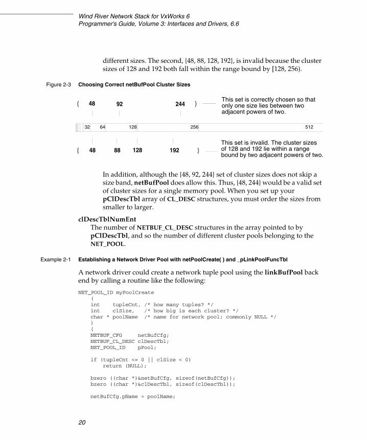
Figure 2-3 shows two examples of sets of cluster sizes. The first, {48, 92, 244}, is valid because there is at least one power of two between the
Wind River Network Stack for VxWorks 6Programmer's Guide, Volume 3: Interfaces and Drivers, 6.6
20
different sizes. The second, {48, 88, 128, 192}, is invalid because the cluster sizes of 128 and 192 both fall within the range bound by [128, 256).
In addition, although the {48, 92, 244} set of cluster sizes does not skip a size band, netBufPool does allow this. Thus, {48, 244} would be a valid set of cluster sizes for a single memory pool. When you set up your pClDescTbl array of CL_DESC structures, you must order the sizes from smaller to larger.
clDescTblNumEnt The number of NETBUF_CL_DESC structures in the array pointed to by pClDescTbl, and so the number of different cluster pools belonging to the NET_POOL.
Example 2-1 Establishing a Network Driver Pool with netPoolCreate( ) and _pLinkPoolFuncTbl
A network driver could create a network tuple pool using the linkBufPool back end by calling a routine like the following:
NET_POOL_ID myPoolCreate(int tupleCnt, /* how many tuples? */int clSize, /* how big is each cluster? */char * poolName /* name for network pool; commonly NULL */){NETBUF_CFG netBufCfg;NETBUF_CL_DESC clDescTbl;NET_POOL_ID pPool;
if (tupleCnt <= 0 || clSize < 0)return (NULL);
bzero ((char *)&netBufCfg, sizeof(netBufCfg));bzero ((char *)&clDescTbl, sizeof(clDescTbl));
netBufCfg.pName = poolName;
Figure 2-3 Choosing Correct netBufPool Cluster Sizes
5122561286432
48 92 244 }{
128 19288 }{ 48
This set is correctly chosen so thatonly one size lies between twoadjacent powers of two.
This set is invalid. The cluster sizesof 128 and 192 lie within a range bound by two adjacent powers of two.
2 Configuring and Managing Memory2.3 netBufLib Buffer Pools
21
2
netBufCfg.attributes = ATTR_AC_SH_ISR;netBufCfg.ctrlNumber = tupleCnt;
if (size > 0){netBufCfg.clDescTblNumEnt = 1;netBufCfg.pClDescTbl = &clDescTbl;clDescTbl.clNum = tupleCnt;clDescTbl.clSize = clSize;}
pPool = netPoolCreate (&netBufCfg, _pLinkPoolFuncTbl);
return (pPool);}
The driver must specify a cluster size big enough for the maximum receivable frame. The netPoolCreate( ) call will round up the specified cluster size to a multiple of NETBUF_ALIGN (64), and return NETBUF_ALIGNED clusters.
In the current release, if size is at least 1500, netPoolCreate( ) will also add the default cluster offset specified by the NETBUF_LEADING_CLSPACE_DRV parameter of component INCLUDE_NETBUFLIB to the requested cluster size, and arrange that tuples allocated from the pool have their mBlkHdr.mData pointers adjusted to point that same offset after the start of the cluster.
This function also supports the much less common case of creating a pool with only bare M_LINKs and no clusters, by passing zero for clSize.
netPoolInit( )
Call the netPoolInit( ) routine to initialize a netBufLib network pool. You must first allocate memory for the NET_POOL structure as well as the clusters, M_BLKs, and CL_BLKs.
Pools that you create with netPoolInit( ) do not support some administrative capabilities of pools that you create using netPoolCreate( ) (see the discussion of these capabilities in 2.3.2 Creating netBufLib Pools, p.16). However, pools created with netPoolInit( ) and netPoolCreate( ) are equivalent in regard to pool back end support and basic allocation/freeing of M_BLKs, CL_BLKs, and clusters.
STATUS netPoolInit(NET_POOL_ID pNetPool, /* pointer to a net pool */M_CL_CONFIG * pMclBlkConfig, /* pointer to a mBlk configuration */CL_DESC * pClDescTbl, /* pointer to cluster desc table */int clDescTblNumEnt, /* number of cluster desc entries */POOL_FUNC * pFuncTbl /* pointer to pool function table */)
Wind River Network Stack for VxWorks 6Programmer's Guide, Volume 3: Interfaces and Drivers, 6.6
22
The parameters that you pass to netPoolInit( ) are as follows:
pNetPoolA pointer to a NET_POOL structure that describes the pool to initialize.
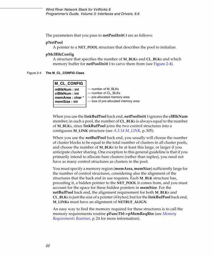
pMclBlkConfig A structure that specifies the number of M_BLKs and CL_BLKs and which memory buffer for netPoolInit( ) to carve them from (see Figure 2-4).
When you use the linkBufPool back end, netPoolInit( ) ignores the clBlkNum member; in such a pool, the number of CL_BLKs is always equal to the number of M_BLKs, since linkBufPool joins the two control structures into a contiguous M_LINK structure (see A.3.14 M_LINK, p.305).
When you use the netBufPool back end, you usually will choose the number of cluster blocks to be equal to the total number of clusters in all cluster pools, and choose the number of M_BLKs to be at least this large, or larger if you anticipate cluster sharing. One exception to this general guideline is that if you primarily intend to allocate bare clusters (rather than tuples), you need not have as many control structures as clusters in the pool.
You must specify a memory region (memArea, memSize) sufficiently large for the number of control structures, considering also the alignment of the structures that the back end in use requires. Each M_BLK structure has, preceding it, a hidden pointer to the NET_POOL it comes from, and you must account for the space for these hidden pointers in memSize. For the netBufPool back end, the alignment requirement for both M_BLKs and CL_BLKs is just the size of a pointer (4 bytes); but for the linkBufPool back end, M_LINKs must have an alignment of NETBUF_ALIGN.
An easy way to find the memory required for these structures is to call the memory requirements routine pFuncTbl->pMemReqRtn (see Memory Requirements Routines, p.24 for more information).
Figure 2-4 The M_CL_CONFIG Class
M_CL_CONFIGmBlkNum : intclBlkNum : intmemArea : char *memSize : int
— number of M_BLKs— number of CL_BLKs— pre-allocated memory area— size of pre-allocated memory area
2 Configuring and Managing Memory2.3 netBufLib Buffer Pools
23
2
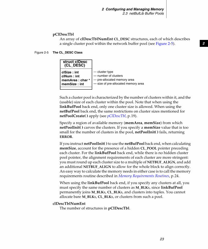
pClDescTbl An array of clDescTblNumEnt CL_DESC structures, each of which describes a single cluster pool within the network buffer pool (see Figure 2-5).
Such a cluster pool is characterized by the number of clusters within it, and the (usable) size of each cluster within the pool. Note that when using the linkBufPool back end, only one cluster size is allowed. When using the netBufPool back end, the same restrictions on cluster sizes mentioned for netPoolCreate( ) apply (see pClDescTbl, p.19).
Specify a region of available memory (memArea, memSize) from which netPoolInit( ) carves the clusters. If you specify a memSize value that is too small for the number of clusters in the pool, netPoolInit( ) fails, returning ERROR.
If you instruct netPoolInit( ) to use the netBufPool back end, when calculating memSize, account for the presence of a hidden CL_POOL pointer preceding each cluster. For the linkBufPool back end, while there is no hidden cluster pool pointer, the alignment requirements of each cluster are more stringent: you must round up each cluster size to a multiple of NETBUF_ALIGN, and add an additional NETBUF_ALIGN to allow for the whole block to align correctly. An easy way to calculate the memory needs in either case is to call the memory requirements routine described in Memory Requirements Routines, p.24.
When using the linkBufPool back end, if you specify any clusters at all, you must specify the same number of clusters as M_BLKs, since linkBufPool permanently joins M_BLKs, CL_BLKs, and clusters into tuples. You cannot allocate bare M_BLKs, CL_BLKs, or clusters from such a pool.
clDescTblNumEnt The number of structures in pClDescTbl.
Figure 2-5 The CL_DESC Class
struct clDesc
clSize : intclNum : intmemArea : char *memSize : int
— cluster type— number of clusters— pre-allocated memory area— size of pre-allocated memory area
(CL_DESC)
Wind River Network Stack for VxWorks 6Programmer's Guide, Volume 3: Interfaces and Drivers, 6.6
24
pFuncTbl The back end’s table of function pointers; set this to _pNetPoolFuncTbl for the netBufPool back end, or _pLinkPoolFuncTbl for the linkBufPool back end.
Memory Requirements Routines
Call the memory requirements routines to determine the amount of memory you need for a particular number of M_BLKs, CL_BLKs, or clusters of a particular size. You can also call memory requirements routines to determine the required alignment of each single M_BLK, CL_BLK, or cluster.
Each of the two back ends netBufPool and linkBufPool provides its own memory requirements routine, and netBufLib also provides a default memory requirements routine, _netMemReqDefault( ), that it uses when the second argument to netPoolCreate( ) is NULL. Alternatively, if you provide a custom POOL_FUNC back end function table, netBufLib obtains its memory requirements routine from the pMemReqRtn member of the POOL_FUNC, or uses _netMemReqDefault( ) if that member is NULL.
The prototype of a netBufLib memory requirements routine is as follows:
int memoryRequirementsRoutine (int type, /* NB_BUFTYPE_[CLUSTER|M_BLK|CL_BLK] */int num, /* number of clusters or control structures */int size /* Cluster size (ignored for control structures) */)
The arguments to this call are as follows:
type What type of memory the caller wants to size, one of the following:
■ NB_BUFTYPE_CLUSTER – cluster memory■ NB_BUFTYPE_M_BLK – M_BLK memory■ NB_BUFTYPE_CL_BLK – CL_BLK memory
num The number of items; when this is zero, the routine returns the required alignment for a single M_BLK, CL_BLK, or cluster of the specified size.
size For clusters only, this indicates the cluster size.
For instance, netPoolCreate( ) would make the following call to find out how much memory is needed for 200 clusters of size 1518 (pMemReq points to the appropriate memory requirements routine):

2 Configuring and Managing Memory2.4 Legacy Network Stack Pools
25
2
size = pMemReq (NB_BUFTYPE_CLUSTER, 200, 1518);
To find the alignment required for each M_BLK, it makes the following call:
align = pMemReq (NB_BUFTYPE_M_BLK, 0, 0);
pMemReq( ) returns a size such that a block of that size is sufficient to hold the specified number of properly aligned items, no matter the alignment of the block. This means that the memory requirements routine adds some extra size to guarantee correct alignment of the first block. To disregard this extra size and find the memory space used by each aligned item, use an expression such as the following:
oneItem = (pMemReq (NB_BUFTYPE_CL_BLK, 2, 0) -pMemReq (NB_BUFTYPE_CL_BLK, 1, 0));
If for some reason you need to modify the alignments that clusters or control structures use, one way to do this is to copy the POOL_FUNC table from the appropriate back end, and replace the pMemReqRtn member in this copy of the table with a pointer to your own memory requirements routine, and then pass the pointer to the copied POOL_FUNC table as the pFuncTbl argument to either netPoolCreate( ) or netPoolInit( ).
For more information, see the reference entry for netPoolInit( ).
2.4 Legacy Network Stack Pools
Previous versions of the Wind River Network Stack made use of two special netBufLib pools: the network stack data pool and the network stack system pool. The stack used the data pool for packets sent to the network and for data in socket send buffers; it used the system pool for control structures such as sockets, route entries, protocol control blocks, socket addresses, and the like.
The network stack no longer uses netBufLib pools internally, except when it communicates with network device drivers. It does not require the legacy network stack data and system pools, and so the component INCLUDE_NET_POOL that includes and configures these pools is not present in the default VxWorks build. However, there may be certain cases in which you need these legacy pools.
For example, you may need the network stack data pool if you must prefix a link-layer header to a packet that a non-network-stack protocol sends, but there is insufficient leading space in the packet’s head cluster to prefix the header. This

Wind River Network Stack for VxWorks 6Programmer's Guide, Volume 3: Interfaces and Drivers, 6.6
26
may occur, for instance, in code that calls muxAddressForm( ) to prefix a link header to a datagram before sending it using muxSend( ). The muxAddressForm( ) routine (or the device-specific formAddress( ) routine that it calls) uses the macro M_PREPEND( ) to prefix space for the link header to the packet. This macro, defined in target/h/wrn/coreip/net/mbuf.h, adjusts pointers and lengths if there is sufficient leading space in the head cluster (and if the head cluster is not shared); otherwise, it calls the routine m_prepend( ), which attempts to allocate a 128-byte tuple from the network stack data pool, to prefix to the existing chain and hold the link header. If the network stack data pool does not exist, this allocation fails (gracefully), and the attempt to send the packet fails.
Another example is an application or protocol that uses the muxTkSend( ) routine to send a packet to an END (not NPT) device, specifying a non-NULL destination MAC address. This routine calls the END’s formAddress( ) routine in this case also.
If your application or protocol calls muxAddressForm( ) or muxTkSend( ) in this way and relies upon M_PREPEND( ) to successfully allocate a tuple, you may need to include the component INCLUDE_NET_POOL in your VxWorks image, and configure the data pool with at least one pool of clusters of size 128-bytes or larger, along with M_BLKs and CL_BLKs. (An alternative is to create a pool of your own for this purpose, and set the NET_POOL pointer _pNetDpool to point to this pool.)
For reference, here is a brief description of the parameters of the INCLUDE_NET_POOL component, used to configure the network stack system pool and network stack data pool. Note that both of these pools use the netBufPool back end.
NUM_SYS_MBLKSThe number of M_BLK structures in the system pool.
NUM_SYS_CLBLKSThe number of CL_BLK structures in the system pool.
PMA_SYSPOOLThe address of a pre-allocated memory buffer that the system pool carves its M_BLKs and CL_BLKs from. To allow the initialization code to allocate this memory buffer, set this parameter and PMS_SYSPOOL to zero.
PMS_SYSPOOLThe size in bytes of the pre-allocated buffer at PMA_SYSPOOL.
2 Configuring and Managing Memory2.4 Legacy Network Stack Pools
27
2
NUM_SYS_n SIZ_SYS_n PMA_SYS_n PMS_SYS_n
These parameters, with n being one of 16, 32, 64, 128, 256, 512, 1024, or 2048, configure a cluster pool within the system pool. The value of SIZ_SYS_n specifies the usable size in bytes of each cluster in the pool, and must be at least n but less than 2 times x. NUM_SYS_n is the number of clusters in the cluster pool. PMA_SYS_n is the address of a pre-allocated buffer of length PMS_SYS_n bytes, which netPoolInit( ) carves into the clusters for the pool. To allow the initialization code to allocate memory itself for the cluster pool, set both PMA_SYS_n and PMS_SYS_n to zero.
NUM_DAT_MBLKSThe number of M_BLK structures in the data pool.
NUM_DAT_CLBLKSThe number of CL_BLK structures in the data pool.
PMA_DATPOOLAddress of a pre-allocated memory buffer to carve for the data pool’s M_BLKs and CL_BLKs. To allow the initialization code to allocate the memory, set this parameter and PMS_DATPOOL to zero.
PMS_DATPOOLThe size in bytes of the pre-allocated buffer at PMA_DATPOOL.
NUM_DAT_n PMA_DAT_n PMS_DAT_n
These parameters, with n being one of 64, 128, 256, 512, 1024, 2048, 4096, 8192, 16384, 32768, or 65536, configure a cluster pool within the data pool. The value of n is the usable size in bytes of each cluster in the pool; unlike the system pool, the data pool’s cluster sizes are hard-coded as powers of two. NUM_DAT_n is the number of clusters in the cluster pool. PMA_DAT_n is the address of a pre-allocated buffer of length PMS_DAT_n bytes, which netPoolInit( ) carves into the clusters for the pool. To allow the initialization code to allocate memory itself for the cluster pool, set both PMA_DAT_n and PMS_DAT_n to zero.

Wind River Network Stack for VxWorks 6Programmer's Guide, Volume 3: Interfaces and Drivers, 6.6
28

29
3Working with Drivers and
Interfaces
3.1 Introduction 29
3.2 Overview of the MUX 30
3.3 Working with Network Driver Instances 32
3.4 Adding Automatic IPv4 Interface Configuration 47
3.5 Using the Reverse ARP Client 51
3.6 Working with IPv4 and IPv6 Tunneling 51
3.7 Using the Shared-Memory Network 63
3.1 Introduction
This chapter shows how to do the following:
■ understand the MUX model■ create and configure network interface devices■ add and delete route table entries■ bring up devices■ configure router advertisement and solicitation■ add automatic IPv4 interface configuration■ use a reverse ARP (RARP) client■ work with IPv4 and IPv6 tunneling
Wind River Network Stack for VxWorks 6Programmer's Guide, Volume 3: Interfaces and Drivers, 6.6
30
3.2 Overview of the MUX
In the Wind River Network Stack, network interface drivers pass information up in the network stack through the mediation of an interface layer known as the MUX. The MUX insulates network services from the specifics of network interface drivers and vice versa.
The MUX interface also decouples the network driver and network protocol layers. This decoupling lets you add new network drivers (not necessarily Ethernet-based) without needing to alter the network service. Likewise, the decoupling lets you add a new network service without needing to modify the existing MUX-based network interface drivers.
The MUX and the OSI Network Model
The OSI Network Model describes seven layers through which data passes when it is transmitted from an application on one machine to a peer on a remote machine.
Starting in the application layer, data passes down through each layer of the stack to the physical layer, which handles the physical transmission to the remote machine. After arriving on the remote machine, data passes up through each layer from the physical to the application.
In the abstract, each layer in the stack is independent of the other layers. A protocol in one layer exchanges messages with a peer protocol in the same layer on remote machines by passing its message to the layer immediately below it. How the message passes down through other layers is not its concern. Ideally, the protocol is insulated from such details.
In practice, network stacks that implement each layer with perfect independence are rare. Within TCP/IP, the protocols that manage the Transport and Network layer routines are sufficiently coupled that they are sometimes referred to as the protocol layer. The MUX is an interface between the data link layer and this protocol layer.
NOTE: The tunneling feature is available only in the Wind River Platforms builds of the network stack. The Wind River General Purpose Platform, VxWorks Edition, does not support tunneling.

3 Working with Drivers and Interfaces3.2 Overview of the MUX
31
3
The MUX is not a new layer. There are no MUX-level protocols that communicate with peers in the MUX of a remote machine. The MUX concerns itself solely with standardizing communication between the protocol and data link layers of a single stack. Because of the MUX, a protocol layer service and network driver do not need direct knowledge of the other’s internal implementation details.
For example, when a network driver needs to pass along a packet it receives, the driver does not directly access any structure or routine within a protocol layer service implementation. Instead, the driver calls a MUX routine that handles the details. The MUX does this by calling the receive routine that the network service registered with the MUX. This design lets any MUX-compatible network service use any MUX-compatible network driver.
Figure 3-1 The OSI Network Model and the MUX
ApplicationThe network applications that usethe data being transferred, forexample HTTP or FTP.
The layer in which data is encrypted,translated, or compressed before it is transmitted.
The layer responsible for establishingand maintaining the connectionbetween communicating machines.
The layer in which data is packagedand tracked to assure that the packetshave been received correctly. TCP, the Transmission Control Protocol, is a transport layer protocol.
The layer that adds routing informationto each data packet. IP, the Internet Protocol, is an example network protocol.
The layer that prepares the packetsfor transmission through the physicallayer and handles problems such as packet collision. Ethernet is a data link protocol.
The actual wiring and hardware thatsupport the network connection.
ProtocolLayer
Presentation
Session
Transport
Network
Data Link
Physical
MUX Interface

Wind River Network Stack for VxWorks 6Programmer's Guide, Volume 3: Interfaces and Drivers, 6.6
32
3.3 Working with Network Driver Instances
Although you can configure the Wind River Network Stack at build time to automatically load, start, and configure multiple network interfaces, you can also configure the stack at run time.
To manually start additional network interfaces at run time, complete the following steps:
1. Use ifconfig -a to display information on each currently-loaded interface. When you add a new interface, you do not want to conflict with any interface that is already loaded. (See Using ifconfig( ), p.35.)
2. Call muxDevLoad( ) to load the driver for the network interface.
3. Call muxIfFuncAdd( ) to install any routines particular to the relationship between a particular interface and a particular service. You can use this routine to assign an address resolution routine, a multicast address resolution routine, or an output routine.
4. Use muxDevStart( ) to initialize the network interface.
5. Call the ipAttach( ) routine to attach (bind) the driver to the service.
6. Assign an IP address and a netmask (IPv4) or prefix (IPv6) to the interface by calling ifconfig( ). If you call ifconfig( ) to bring up inet6, it triggers IPv6 link-local address generation for the interface.
7. Use hostAdd( ) to add a host name to the host table.
8. Check that the interface is loaded and configured correctly by calling the following routines:
NOTE: If your target system includes more than one network interface, you may need to increase the value of the configuration parameter IP_MAX_UNITS. For information on configuring the Wind River Network Stack to automatically start multiple network interfaces, see 4.7.1 Adding a Network Driver, p.109.
NOTE: When you load the network interface drivers and tunnel devices that Wind River supplies, this step is usually handled for you. For example, if you load the pseudo-devices that Wind River supplies, you can skip this step. The tunnel library handles it automatically when it initializes.

3 Working with Drivers and Interfaces3.3 Working with Network Driver Instances
33
3
ifconfig( )List configuration information for network devices (use ifconfig -a). (See Using ifconfig( ), p.35.)
netstat( )Check that the route table has an entry for the device.
hostShow( )Check that the address/hostname is in the host table.
3.3.1 Attaching a Service to a Network Interface
A protocol or service, such as IPv4, must attach itself to one or more network interfaces to communicate with remote peers. When a service attaches to an interface, packets addressed to that interface can flow up to the service. This also lets the service transmit packets out through the interface.
If you want network interfaces to automatically attach to and be configured for a given IP protocol (i.e., IPv4 or IPv6), include the build configuration component INCLUDE_IPNET_IFCONFIG_n and set the value of the configuration parameter IFCONFIG_n (where n is 1, 2, 3, or 4).
Set the IFCONFIG_n parameter to a series of strings, each of which begins with one of the following keywords:
ifnameThe name of the ethernet interface, for example: "ifname eth0". If you simply specify "ifname" without an interface name, the interface name is the END device name.
devnameWhich driver this interface should attach itself to, for example: "devname fei0". The default is "devname driver" which indicates that the interface gets the name of the device to attach itself to from the device boot parameters.
inetThe interface IPv4 address and subnet, for example: "inet 10.1.2.100/24".
You may use one of the following keywords in place of the IPv4 address:
NOTE: For information on the inputs expected by the routines listed above, see the reference entries for each routine.
Wind River Network Stack for VxWorks 6Programmer's Guide, Volume 3: Interfaces and Drivers, 6.6
34
"inet driver" The interface should read its address and mask from the BSP. This is the default setting for the inet keyword.
"inet dhcp" The interface should retrieve its address and mask from a DHCP server. Depending on the DHCP server configuration, the interface might also retrieve its gateway from the server.
"inet rarp" The interface should retrieve its address and mask from a RARP server.
gatewayThe default IPv4 gateway, for example: "gateway 10.1.2.1". You may specify only one default gateway.
If you specify "gateway driver" the interface will take the gateway from the boot parameters.
inet6The interface IPv6 address and subnet, for example: "inet6 3ffe:1:2:3::4/64". You can insert the tentative keyword before the address to instruct the stack to check for address duplication before it assigns the address to the interface, for example: "inet6 tentative 3ffe:1:2:3::4/64".
gateway6The default IPv6 gateway. You may specify only one default gateway.
You may configure only one interface to automatically attach to IPv4 or IPv6, even if your target supports more than one interface. If you want to attach IPv4 or IPv6 to additional interfaces, call ipAttach( ) for each one. Include the INCLUDE_IPATTACH configuration component in your build if you need to use the ipAttach( ) and ipDetach( ) routines.
3.3.2 Configuring a Network Interface with an Address
When a network service attaches to an interface, this allows packets addressed to that interface to flow up to the service. You must assign an address to the interface in order for the interface to know which packets are addressed to it. When you assign an address to an interface, you also need to assign a netmask (IPv4) or prefix (IPv6) that determines whether the interface can access a particular network.
Use ifconfig( ) to set the address and mask associated with a network interface.

3 Working with Drivers and Interfaces3.3 Working with Network Driver Instances
35
3
Using ifconfig( )
This section provides a brief overview of ifconfig( ). For a detailed description of all possible flags and parameter values, see the ifconfig( ) reference entry.
Call the ifconfig( ) routine to do either of the following tasks:
■ Retrieve configuration information on an interface.■ Assign an address and a netmask or prefix to a network interface.
You must include the INCLUDE_IFCONFIG configuration component in your build if you want to call the ifconfig( ) routine.
You can call the ifconfig( ) routine in the C-interpreter and in the command-interpreter. Examples of calls in the C-interpreter are prefaced with “->”. Examples in the command-interpreter are prefaced with “#”.
Use the following syntax when calling ifconfig( ) from the C-interpreter:
-> ifconfig "[flags] [interfaceName] [protocol] [command]"
Use the following syntax when calling ifconfig( ) from the command-interpreter:
# ifconfig [flags] [interfaceName] [protocol] [command]
ifconfig( ) Parameters
Pass the following parameters to ifconfig( ):
flags
-aRun the command on all interfaces.
-V virtualRouter Run the command in virtual router instance virtualRouter.
The valid flag combinations are as follows:
-> ifconfig "-V virtualRouter -a"-> ifconfig "-V virtualRouter [interfaceName] [protocol] [command [command [...]]]"-> ifconfig "[interfaceName] [protocol] [command [command [...]]]"
interfaceNameThe name of the network interface for ifconfig( ) to report on.
protocolWhich network protocol the command applies to. This can be either inet (IPv4 domain) or inet6 (IPv6 domain).
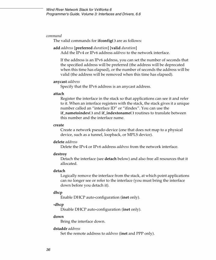
Wind River Network Stack for VxWorks 6Programmer's Guide, Volume 3: Interfaces and Drivers, 6.6
36
commandThe valid commands for ifconfig( ) are as follows:
add address [preferred duration] [valid duration] Add the IPv4 or IPv6 address address to the network interface.
If the address is an IPv6 address, you can set the number of seconds that the specified address will be preferred (the address will be deprecated when this time has elapsed), or the number of seconds the address will be valid (the address will be removed when this time has elapsed).
anycast address Specify that the IPv6 address is an anycast address.
attach Register the interface in the stack so that applications can see it and refer to it. When an interface registers with the stack, the stack gives it a unique number called an “interface ID” or “ifindex”. You can use the if_nametoindex( ) and if_indextoname( ) routines to translate between this number and the interface name.
create Create a network pseudo-device (one that does not map to a physical device, such as a tunnel, loopback, or MPLS device).
delete address Delete the IPv4 or IPv6 address address from the network interface.
destroy Detach the interface (see detach below) and also free all resources that it allocated.
detach Logically remove the interface from the stack, at which point applications can no longer see or refer to the interface (you must bring the interface down before you detach it).
dhcp Enable DHCP auto-configuration (inet only).
-dhcpDisable DHCP auto-configuration (inet only).
down Bring the interface down.
dstaddr address Set the remote address to address (inet and PPP only).

3 Working with Drivers and Interfaces3.3 Working with Network Driver Instances
37
3
inet address Change the primary IPv4 address to address.
lladdr address Set the link layer address to address.
link[0-2] Enable special processing, of a sort that is particular to the network interface type, at the link level.
-link[0-2] Disable special processing at the link level.
link0 For GRE tunnels, enable minimal encapsulation (RFC 2002).
-link0 For GRE tunnels, use normal GRE tunnel operation.
lladdr address Set the interface link address to address.
mtu unitSet the maximum transmission unit (MTU) of the interface to unit.
netmask mask Set the IPv4 netmask; mask is in dotted quad notation. The netmask will default to 255.0.0.0 for class A, 255.255.0.0 for class B and 255.255.255.0 for class C addresses.
prefixlen length Set the number of address bits used for dividing networks into subnets (inet6 only). This must be an integer value between 0 and 128; the default is 64.
promiscEnable promiscuous mode at the interface.
-promiscDisable promiscuous mode at the interface.
tentative address Set the tentative bit in the specified IPv6 address.
-tentative address Clear the tentative bit in the specified IPv6 address.
tunnel localAddress remoteAddress [ttl] If the interface is a GRE or GIF pseudo-interface, set the tunnel endpoint.
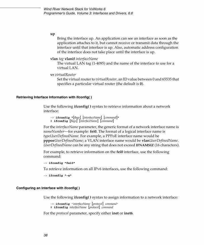
Wind River Network Stack for VxWorks 6Programmer's Guide, Volume 3: Interfaces and Drivers, 6.6
38
upBring the interface up. An application can see an interface as soon as the application attaches to it, but cannot receive or transmit data through the interface until that interface is up. Also, automatic address configuration of the interface does not take place until the interface is up.
vlan tag vlanif interfaceName The virtual LAN tag (1-4095) and the name of the interface to use for a virtual LAN.
vr virtualRouter Set the virtual router to virtualRouter, an ID value between 0 and 65535 that specifies a particular virtual router (the default is 0).
Retrieving Interface Information with ifconfig( )
Use the following ifconfig( ) syntax to retrieve information about a network interface:
-> ifconfig "[flags] [interfaceName] [command]" # ifconfig [flags] [interfaceName] [command]
For the interfaceName parameter, the generic format of a network interface name is nameNumber—for example: fei0. The format of a logical interface name is typeUserDefinedName. For example, a PPPoE interface name would be pppoeUserDefinedName; a VLAN interface name would be vlanUserDefinedName. UserDefinedName can be any string that does not exceed IFNAMSIZ (16 characters).
For example, to retrieve information on the fei0 interface, use the following command:
-> ifconfig "fei0"
To retrieve information on all IPv6 interfaces, use the following command:
-> ifconfig "-a"
Configuring an Interface with ifconfig( )
Use the following ifconfig( ) syntax to assign information to a network interface:
-> ifconfig "interfaceName [protocol] command" # ifconfig interfaceName [protocol] command
For the protocol parameter, specify either inet or inet6.
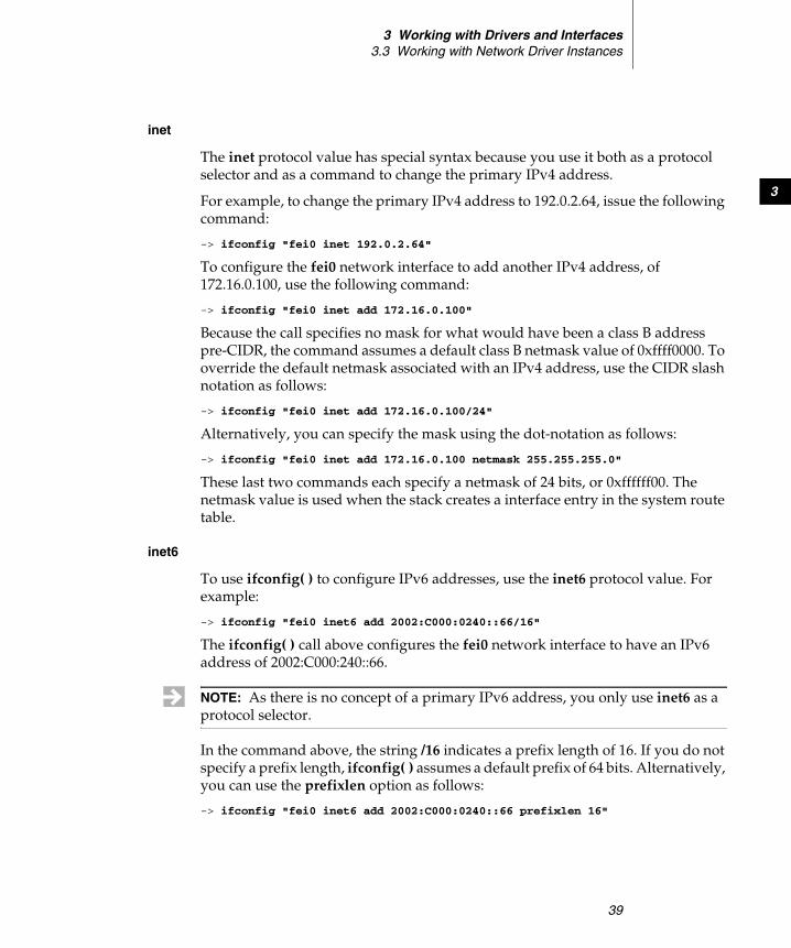
3 Working with Drivers and Interfaces3.3 Working with Network Driver Instances
39
3
inet
The inet protocol value has special syntax because you use it both as a protocol selector and as a command to change the primary IPv4 address.
For example, to change the primary IPv4 address to 192.0.2.64, issue the following command:
-> ifconfig "fei0 inet 192.0.2.64"
To configure the fei0 network interface to add another IPv4 address, of 172.16.0.100, use the following command:
-> ifconfig "fei0 inet add 172.16.0.100"
Because the call specifies no mask for what would have been a class B address pre-CIDR, the command assumes a default class B netmask value of 0xffff0000. To override the default netmask associated with an IPv4 address, use the CIDR slash notation as follows:
-> ifconfig "fei0 inet add 172.16.0.100/24"
Alternatively, you can specify the mask using the dot-notation as follows:
-> ifconfig "fei0 inet add 172.16.0.100 netmask 255.255.255.0"
These last two commands each specify a netmask of 24 bits, or 0xffffff00. The netmask value is used when the stack creates a interface entry in the system route table.
inet6
To use ifconfig( ) to configure IPv6 addresses, use the inet6 protocol value. For example:
-> ifconfig "fei0 inet6 add 2002:C000:0240::66/16"
The ifconfig( ) call above configures the fei0 network interface to have an IPv6 address of 2002:C000:240::66.
In the command above, the string /16 indicates a prefix length of 16. If you do not specify a prefix length, ifconfig( ) assumes a default prefix of 64 bits. Alternatively, you can use the prefixlen option as follows:
-> ifconfig "fei0 inet6 add 2002:C000:0240::66 prefixlen 16"
NOTE: As there is no concept of a primary IPv6 address, you only use inet6 as a protocol selector.

Wind River Network Stack for VxWorks 6Programmer's Guide, Volume 3: Interfaces and Drivers, 6.6
40
This example address is a 6to4 IPv6 address with a local IPv4 tunnel address of 192.0.2.64. The IPv4 notation uses base 10; the IPv6 notation uses base 16. Thus, 192.0.2.64 is 0xC0000240, which is written as C000:0240 in IPv6 notation.
Creating a Pseudo-Interface with ifconfig( )
You can call the ifconfig( ) routine to create pseudo-interfaces (also called logical interfaces) such as VLAN interfaces and tunnels.
For example, to create a VLAN interface that puts the VLAN tag 1234 on all traffic sent to the 10.0.0.0/8 network, that is assigned the address 10.1.2.3, and that uses fei0 as the underlying physical interface, issue the following series of commands:
-> ifconfig "vlan10 create"-> ifconfig "vlan10 vlan 1234 vlanif fei0"-> ifconfig "vlan10 inet 10.1.2.3"-> ifconfig "vlan10 up"
You can also chain these commands together:
-> ifconfig "vlan10 create vlan 1234 vlanif fei0 inet 10.1.2.3 up"
3.3.3 Editing the Route Table
If you have accidentally misconfigured a network interface, you must delete the problematic entry from the route table. You may also want to edit the route table manually when you first test the routing stack software or a new application that you have written or ported for that stack. At such times, you may find it convenient to enter a default network route. In addition, in order to establish useful tunnels through the IPv4 Internet you must add route table entries that specify which networks’ traffic should be sent through the tunnel interface. For more information, see 3.6 Working with IPv4 and IPv6 Tunneling, p.51.
To edit the route table from the command line, call routec, a port of the UNIX route utility. With this routine, you can view the route table contents as well as add and delete route entries.
Use the routec command interactively, from the command-line. To manipulate the routing table from within compiled code, use a standard routing socket instead. For more information on routing socket messages, see the Wind River Network Stack Programmer’s Guide, Volume 1.

3 Working with Drivers and Interfaces3.3 Working with Network Driver Instances
41
3
3.3.4 Using routec( ) to Add or Delete Route Table Entries
Call routec( ) to add or delete route table entries for local hosts and gateways. To use routec( ), you must include the INCLUDE_ROUTECMD component in your build.
The following examples cover most uses of the command. To verify the proper operation of a routec( ) command, issue the following command:
-> netstat "-r"
Adding or Deleting an IPv4 Network Route
To add an IPv4 network route, issue the following command:
-> routec "add -net -netmask netmaskValue destinationNetwork gatewayAddress"
For example:
-> routec "add -net -netmask 255.255.255.0 192.168.10.0 192.168.1.1"
To delete this route, replace add with delete.
Adding or Deleting an IPv6 Network Route
To add an IPv6 network route, issue the following command:
-> routec "add -net -inet6 -prefixlen numberdestinationNetwork gatewayAddress%scope"
You can specify the scope value in gatewayAddress%scope with a network interface name. This specifies that the scope is the local link available through that network interface.
For example:
-> routec "add -net -inet6 -prefixlen 642001:DB8:84b1:7600::fe80::20f:ff:fe00:101%fei0"
To delete this route, replace add with delete.
Adding or Deleting an IPv4 Host Route
To add an IPv4 host route, issue the following command:
-> routec "add -host hostAddress gatewayAddress"
For example:
-> routec "add -host 192.168.13.76 192.168.1.1"
To delete this route, replace add with delete.

Wind River Network Stack for VxWorks 6Programmer's Guide, Volume 3: Interfaces and Drivers, 6.6
42
Adding or Deleting an IPv6 Host Route
To add an IPv6 host route, issue the following command:
-> routec "add -host -inet6 hostAddress gatewayAddress%scope"
For example:
-> routec "add -host -inet6 2001:DB8:84b1:7600:0205:00ff:fe00:0101 fe80::20f:ff:fe00:101%fei0"
To delete this route, replace add with delete.
Adding or Deleting a Default IPv4 Route
To add a default IPv4 route, issue the following command:
-> routec "add default IPv4gatewayAddress"
For example:
-> routec "add default 192.168.1.1"
To delete this route, replace add with delete.
Adding or Deleting a Default IPv6 Route
To add a default IPv6 route, issue the following command:
-> routec "add -inet6 default IPv6gatewayAddress%scope"
For example:
-> routec "add -inet6 default fe80::20f:ff:fe00:101%fei0"
To delete this route, replace add with delete.
3.3.5 Fixing Interfaces That Have Erroneous Addresses
When you call ifconfig( ) you create a local entry in the route table. Local entries in the route table identify network interfaces on the local host.
To reconfigure a network interface using ifconfig( ), issue one of the following commands:
-> ifconfig "interfaceName inet delete oldIPv4address add newIPv4address"-> ifconfig "interfaceName inet6 delete oldIPv6address add newIPv6address"
If you are changing the primary IPv4 address, issue the following command:
-> ifconfig "interfaceName inet newIPv4address"
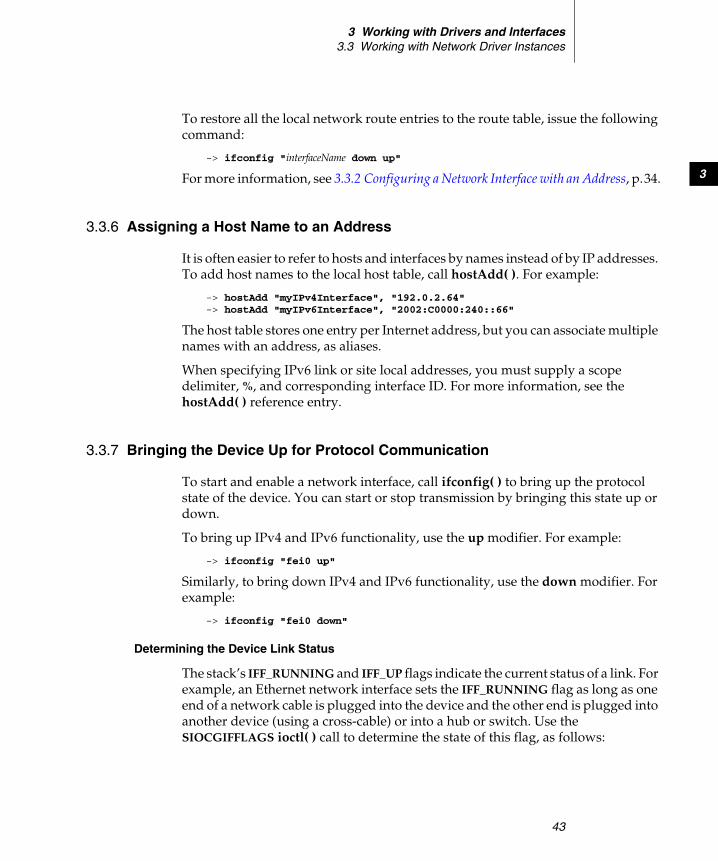
3 Working with Drivers and Interfaces3.3 Working with Network Driver Instances
43
3
To restore all the local network route entries to the route table, issue the following command:
-> ifconfig "interfaceName down up"
For more information, see 3.3.2 Configuring a Network Interface with an Address, p.34.
3.3.6 Assigning a Host Name to an Address
It is often easier to refer to hosts and interfaces by names instead of by IP addresses. To add host names to the local host table, call hostAdd( ). For example:
-> hostAdd "myIPv4Interface", "192.0.2.64"-> hostAdd "myIPv6Interface", "2002:C0000:240::66"
The host table stores one entry per Internet address, but you can associate multiple names with an address, as aliases.
When specifying IPv6 link or site local addresses, you must supply a scope delimiter, %, and corresponding interface ID. For more information, see the hostAdd( ) reference entry.
3.3.7 Bringing the Device Up for Protocol Communication
To start and enable a network interface, call ifconfig( ) to bring up the protocol state of the device. You can start or stop transmission by bringing this state up or down.
To bring up IPv4 and IPv6 functionality, use the up modifier. For example:
-> ifconfig "fei0 up"
Similarly, to bring down IPv4 and IPv6 functionality, use the down modifier. For example:
-> ifconfig "fei0 down"
Determining the Device Link Status
The stack’s IFF_RUNNING and IFF_UP flags indicate the current status of a link. For example, an Ethernet network interface sets the IFF_RUNNING flag as long as one end of a network cable is plugged into the device and the other end is plugged into another device (using a cross-cable) or into a hub or switch. Use the SIOCGIFFLAGS ioctl( ) call to determine the state of this flag, as follows:
Wind River Network Stack for VxWorks 6Programmer's Guide, Volume 3: Interfaces and Drivers, 6.6
44
struct ifreq ifp;int fd = socket descriptor for the link ;ioctl (fd, SIOCGIFFLAGS, &ifp);if (ifp.ifr_flags & IFF_RUNNING)
{// interface is running}
if (ifp.ifr_flags & IFF_UP){// interface is UP}
3.3.8 Configuring Router Advertisement and Solicitation for an Interface
Router Advertisement
The Wind River Network Stack supports both the host and router side of router advertisement, for both IPv4 and IPv6.
Including Router Advertisement
For IPv6, to include router advertisement in your project, include the INCLUDE_IPRADVD component.
For IPv4, router advertisement is included by default. To remove it, undefine IPNET_USE_RFC1256 in installDir/components/ip_net2-6.n/ipnet2/ config/ipnet_config.h and rebuild the stack.
Configuring Router Advertisement with sysvar( )
The ipnet_radvd daemon handles router advertisement messages, and sends out router advertisements and answers to router solicitations.
You must specify the following information for each link that the daemon serves:
■ which links to listen to and send to■ which prefixes to announce to each link
The sysvar( ) command controls the ipnet_radvd daemon. For details on using the sysvar command, see the Wind River Network Stack for VxWorks 6 Programmer’s Guide, Volume 1. In order to call sysvar( ), you must include INCLUDE_IPCOM_SYSVAR_CMD in your build.
If you set the parameter ipnet.inet6.AcceptRtAdv to 1, as in the following example, this determines that a received router advertisement is accepted and processed:
3 Working with Drivers and Interfaces3.3 Working with Network Driver Instances
45
3
-> sysvar set "ipnet.inet6.AcceptRtAdv", 1
To use router advertisement, first declare a list of interfaces for which the advertisement should be done:
-> sysvar set "ipnet.inet6.radvd.interfaces"
interfaces is one or more interface names, delimited by spaces or commas; for example: fei0 fei1 fei2
Set the following parameters for every interface that you declare in the above sysvar( ) command; the values are valid only for the interface specified by interfaceName in each parameter (such as fei0 or fei1).
ipnet.inet6.radvd.interfaceName.AdvManagedFlagControls whether the managed flag should be set or not in send messages. If you set this to 1, hosts find their addresses through some managed mechanism like DHCPv6. If you set this to 0, hosts generate addresses through stateless addresses configuration. The default value is 0.
ipnet.inet6.radvd.interfaceName.AdvOtherConfigFlag If you set this to 1, hosts configure non-addresses related options, like DNS servers, through DHCPv6. The default value is 0.
ipnet.inet6.radvd.interfaceName.AdvHomeAgentFlag If you set this to 1, this router acts as a home agent (RFC 3775). The default value is 0.
ipnet.inet6.radvd.interfaceName.AdvIntervalOpt Advertisement interval option (RFC 3775). The default value is 0.
ipnet.inet6.radvd.interfaceName.AdvHomeAgentOpt Home Agent Information option (RFC 3775). The default value is 0.
ipnet.inet6.radvd.interfaceName.AdvHomeAgentOptLifetime Home agent lifetime. The default value is AdvDefaultLifetime.
ipnet.inet6.radvd.interfaceName.AdvHomeAgentOptPreference Home agent preference. The default value is 0.
ipnet.inet6.radvd.interfaceName.MinRtrAdvInterval The shortest interval, in milliseconds, between two unsolicited router advertisements. The default value is 200000.
ipnet.inet6.radvd.interfaceName.MaxRtrAdvInterval The longest interval, in milliseconds, between two unsolicited router advertisements. The default value is 600000.

Wind River Network Stack for VxWorks 6Programmer's Guide, Volume 3: Interfaces and Drivers, 6.6
46
ipnet.inet6.radvd.interfaceName.MinDelayBetweenRAs The shortest interval between solicited router advertisements, in milliseconds. The default value is 3000.
ipnet.inet6.radvd.interfaceName.AdvPrefixList A list of user-defined prefix names. The default value is an empty list.
Prefix Configuration
The following parameters are per interface (for example, fei0) and per user-defined prefix name (for example, ex_prefix).
ipnet.inet6.radvd.interfaceName.prefix.prefixName Prefix definition. This is a required field with no default. For example: “2002:0a01:0201::/64”.
ipnet.inet6.radvd.interfaceName.prefix.prefixName.AdvOnLinkFlagSet this to 1 (one) if this prefix is local to this link. The default value is 1.
ipnet.inet6.radvd.interfaceName.prefix.prefixName.AdvAutonomousFlagSet this to 1 (one) if this prefix can be used for automatic address generation. The default value is 1.
ipnet.inet6.radvd.interfaceName.prefix.prefixName.AdvRouterAddressFlagRouter address flag. The prefix is the router’s complete address (RFC 3775). The default value is 0.
ipnet.inet6.radvd.interfaceName.prefix.prefixName.AdvValidLifetimeThe duration, in seconds, that this prefix is valid. The default value is -1, which means an infinite lifetime.
ipnet.inet6.radvd.interfaceName.prefix.prefixName.AdvPreferredLifetimeThe duration, in seconds, that this prefix is preferred. The default value is 604800. A value of 0xffffffff (-1) indicates an infinite duration.
Router Solicitation
The Wind River Network Stack supports both the host and router side of router solicitation for both IPv4 and IPv6.
Use sysvar( ) to set the following parameters for router solicitation:
ipnet.inet.rtdisc.PerformRouterDiscoverySet this to 1 (one) or yes to enable the entire router solicitation portion of RFC 1256; set this to 0 (zero) or no to disable this feature. The default value is 1.
3 Working with Drivers and Interfaces3.4 Adding Automatic IPv4 Interface Configuration
47
3
interfaceName.inet.rtdisc.PerformRouterDiscoverySet this to 1 (one) or yes to enable the router solicitation portion of RFC 1256 on the specified interface; set this to 0 (zero) or no to disable this feature. The default value is 1.
interfaceName.inet.rtdisc.SolicitationAddressSpecifies the address to send the solicitations to for this interface. Valid values are: 224.0.0.2 or 255.255.255.255. The default value is 224.0.0.2.
3.4 Adding Automatic IPv4 Interface Configuration
A target can use IPv4 auto-configuration (Auto IP) to join a local network automatically without being either manually configured or built with hard-coded IPv4 addresses. In addition, if a DHCP agent later assigns a routable IPv4 address to the target’s interface, the target uses that address instead of the auto-configured address. In such a case, the target retains the auto-configured address, defends it in case another interface on the network attempts to assume it, and uses it if the routable IPv4 address is removed.
Configuring VxWorks for Auto IP
To configure VxWorks to use Auto IP, take the following steps:
1. Add the interface that you want Auto IP to configure to the configuration parameter IFCONFIG_1. For instance, to add eth0, add the following string to the IFCONFIG_1 parameter:
"ifname eth0", "devname driver"
2. Include the IPv4 AutoIP Components (FOLDER_AUTOIP) and IPCOM ifconfig commands (INCLUDE_IPIFCONFIG_CMD) components.
3. Include the INCLUDE_IPAIP component and set the autoIP interface list (INET_IPAIP_IFNAME_LIST) configuration parameter to the name of the interface, for instance: "eth0".
4. Build the project. If the interface you selected has an assigned IPv4 address, you must delete this address before Auto IP can configure the interface. To do this, follow these steps:
Wind River Network Stack for VxWorks 6Programmer's Guide, Volume 3: Interfaces and Drivers, 6.6
48
a. Run ifconfig to determine assigned IP address, for instance with the following command:-> ifconfig "eth0" eth0 Link type:Ethernet HWaddr 00:1e:a0:a0:1e:01Queue:none inet 192.168.195.7 mask 255.255.0.0
b. Delete that IP address, for instance with the following command:-> ifconfig "eth0 inet delete 192.168.195.7"
c. AutoIP will start automatically. You can see the new address assignment with ifconfig, for instance as follows:-> ifconfig "eth0" eth0 Link type:Ethernet HWaddr 00:1e:a0:a0:1e:01Queue:none inet 169.254.134.89 mask 255.255.0.0
Configuring Auto IP
The run-time sysvar parameters and corresponding build configuration parameters shown in Table 3-1 are available when you include INCLUDE_IPAIP. For details on using the sysvar command, see the Wind River Network Stack for VxWorks 6 Programmer’s Guide, Volume 1. In order to call sysvar( ), you must include INCLUDE_IPCOM_SYSVAR_CMD in your build.
Table 3-1 Auto IP Server Build Parameters
Workbench Description, Parameter Name, and sysvarDefault Value& Data Type
autoIP interface listINET_IPAIP_IFNAME_LISTipnet.inet.linklocal.interfaces
A list of the interfaces for which Auto IP will configure link-local addresses unless another IPv4 address is added by some other mechanism. The list delimiter is a comma and/or a space.
""
char *
autoIP probe wait timeINET_IPAIP_PROBE_WAITipnet.inet.linklocal.PROBE_WAIT
The target will wait [0..PROBE_WAIT] seconds before creating a link-local IPv4 address and checking it for uniqueness.
"1"
char *

3 Working with Drivers and Interfaces3.4 Adding Automatic IPv4 Interface Configuration
49
3autoIP probe count INET_IPAIP_PROBE_NUMipnet.inet.linklocal.PROBE_NUM
The number of ARP requests the target will send to check a link-local address for uniqueness before it accepts the address.
"3"
char *
autoIP min problem time INET_IPAIP_PROBE_MINipnet.inet.linklocal.PROBE_MIN
Auto IP sends the next probe between PROBE_MIN and PROBE_MAX seconds after the previous one.
"1"
char *
autoIP max problem time INET_IPAIP_PROBE_MAXipnet.inet.linklocal.PROBE_MAX
Auto IP sends the next probe between PROBE_MIN and PROBE_MAX seconds after the previous one.
"3"
char *
autoIP announce wait timeINET_IPAIP_ANNOUNCE_WAITipnet.inet.linklocal.ANNOUNCE_WAIT
Time (in seconds) that Auto IP waits before it starts to announce the address it selects. It will not defend the address if it hears another announcement during this period.
"2"
char *
autoIP number of announcementsINET_IPAIP_ANNOUNCE_NUMipnet.inet.linklocal.ANNOUNCE_NUM
Number of announcements.
"2"
char *
autoIP announcements interval INET_IPAIP_ANNOUNCE_INTERVALipnet.inet.linklocal.ANNOUNCE_INTERVAL
Seconds between announcements.
"2"
char *
Table 3-1 Auto IP Server Build Parameters (cont’d)
Workbench Description, Parameter Name, and sysvarDefault Value& Data Type
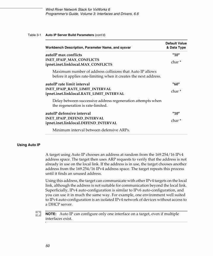
Wind River Network Stack for VxWorks 6Programmer's Guide, Volume 3: Interfaces and Drivers, 6.6
50
Using Auto IP
A target using Auto IP chooses an address at random from the 169.254/16 IPv4 address space. The target then uses ARP requests to verify that the address is not already in use on the local link. If the address is in use, the target chooses another address from the 169.254/16 IPv4 address space. The target repeats this process until it finds an unused address.
Using this address, the target can communicate with other IPv4 targets on the local link, although the address is not suitable for communication beyond the local link. Superficially, IPv4 auto-configuration is similar to IPv6 auto-configuration, and you can use it in much the same way. For example, one environment well suited to IPv4 auto-configuration is an isolated IPv4 network of devices without access to a DHCP server.
autoIP max conflicts INET_IPAIP_MAX_CONFLICTSipnet.inet.linklocal.MAX_CONFLICTS
Maximum number of address collisions that Auto IP allows before it applies rate-limiting when it creates the next address.
"10"
char *
autoIP rate limit interval INET_IPAIP_RATE_LIMIT_INTERVALipnet.inet.linklocal.RATE_LIMIT_INTERVAL
Delay between successive address regeneration attempts when the regeneration is rate-limited.
"60"
char *
autoIP defensive intervalINET_IPAIP_DEFEND_INTERVALipnet.inet.linklocal.DEFEND_INTERVAL
Minimum interval between defensive ARPs.
"10"
char *
Table 3-1 Auto IP Server Build Parameters (cont’d)
Workbench Description, Parameter Name, and sysvarDefault Value& Data Type
NOTE: Auto IP can configure only one interface on a target, even if multiple interfaces exist.
3 Working with Drivers and Interfaces3.5 Using the Reverse ARP Client
51
3
3.5 Using the Reverse ARP Client
The Wind River Network Stack includes a reverse ARP (RARP) client.
Configuring RARP
Use the IFCONFIG_n parameter to configure RARP for a given interface. See 3.3.1 Attaching a Service to a Network Interface, p.33, for information on IFCONFIG_n.
Using the RARP Client
A VxWorks target can use the RARP client to broadcast a RARP request packet containing its hardware address. If there is a RARP server on the local network, the server responds with a RARP response packet. This packet contains the IP address that the RARP host associates with the hardware address in the RARP request packet.
Diskless workstations sometimes use RARP at boot time to request an IP address. If you are writing boot code for a device that requires an external source to supply more than just an IP address, consider using BOOTP or DHCP.
3.6 Working with IPv4 and IPv6 Tunneling
In this document, tunneling through an IPv4 Internet refers to the encapsulation of data (such as an IPv4 or an IPv6 packet for a VPN connection) in an IPv4 packet that is then transmitted to an IPv4-addressed destination. At the destination, the data is retrieved from the IPv4 packet and processed. If the data retrieved is an IPv6 packet, and the receiving stack is a dual IPv4/IPv6 stack, the stack can forward the IPv6 packet out onto the IPv6 Internet.
A tunnel attaches to the stack as a network interface. Create tunneling interfaces with the ifconfig command.
NOTE: RARP is an older protocol that, for most purposes, is now superseded by BOOTP, which is itself largely superseded by DHCP.
NOTE: IPsec does its own IP tunneling for associations running in tunneling mode; therefore, an IPsec tunnel will not show up as a regular network interface.
Wind River Network Stack for VxWorks 6Programmer's Guide, Volume 3: Interfaces and Drivers, 6.6
52
Tunnels can be either configured or automatic. A configured tunnel determines the endpoint addresses by configuration information on the encapsulating node. An automatic tunnel determines the IPv4 endpoints from the addresses of the embedded IPv6 datagram.
IPv4 multicast tunneling determines the endpoints through Neighbor Discovery. See the Wind River Network Stack for VxWorks 6 Programmer’s Guide, Volume 1 for more on Neighbor Discovery.
3.6.1 Configuring VxWorks for Tunneling
The Wind River Network Stack includes the following tunneling components:
■ 6over4 Tunnel Interface Driver (RFC 2529)■ 6to4 Tunnel Interface Driver (RFC 3056)■ GIF Tunnel Interface Driver (RFC 1853, RFC 2473)■ GRE Tunnel Interface Driver (RFC 2002, RFC 2784)■ SIT Tunnel Interface Driver
The INCLUDE_IPNET_USE_TUNNEL (Tunnel Interface support) component enables these.
GIF Tunnel Interface Driver
The INCLUDE_IPNET_USE_TUNNEL (Tunnel Interface support) component pulls in modules that implement the gif tunneling pseudo-device for IPv4 and IPv6. GIF can tunnel IPv4 and IPv6 over IPv4 or IPv6. GIF tunneling is configured as opposed to automatic (which is to say that you must specify the endpoints when the tunnel is created, rather than relying on the endpoints being extracted from the addresses of the protocol being tunneled); you can configure endpoints per route entry.
The GIF component has no configuration parameters and is always included when you enable tunneling support.
Use ifconfig to create GIF tunnel interfaces. Interfaces for GIF tunnels must begin with “gif”. For example:
_-> ifconfig "gif0 create"
To set tunnel endpoints on a GIF tunnel, use ifconfig:
NOTE: Although this chapter focuses on host-to-host tunnels, you can also set up host-to-router tunnels, router-to-router tunnels, and other permutations.

3 Working with Drivers and Interfaces3.6 Working with IPv4 and IPv6 Tunneling
53
3
ifconfig "interfaceName [inet | inet6] tunnel localAddress remoteAddress"
For example, to set the endpoints on a GIF tunnel over IPv4:
-> ifconfig "gif0 inet tunnel 192.168.0.10 10.1.2.3"
To set the endpoints on a GIF tunnel over IPv6:
-> ifconfig "gif0 inet6 tunnel 2001:10::10 2001:20::1"
GRE Tunnel Interface Driver
The INCLUDE_IPNET_USE_TUNNEL (Tunnel Interface support) component pulls in support for the gre tunneling pseudo-devices for IPv4 and IPv6. GRE can tunnel IPv4 and IPv6 over IPv4 or IPv6. Like GIF tunneling, GRE tunnels are configured as opposed to automatic (which is to say that you must specify the endpoints when the tunnel is created, rather than relying on the endpoints being extracted from the addresses of the protocol being tunneled); you can configure endpoints per route entry. GRE has a version field set to 0 and provides an optional payload checksum.
GRE can be run in “minimal encapsulation” when tunneling IPv4 over IPv4 (described in RFC 2002).
Use ifconfig to create tunnel interfaces. Interfaces for GRE tunnels must begin with “gre”. For example:
-> ifconfig "greTunnel create"
To set tunnel endpoints on a GRE tunnel, use ifconfig:
ifconfig "interfaceName [inet | inet6] tunnel localAddress remoteAddress"
For example:
-> ifconfig "greTunnel inet6 tunnel 2001:10::10 2001:20::1"
6over4 Tunnel Interface Driver
The INCLUDE_IPNET_USE_TUNNEL (Tunnel Interface support) component pulls in support for the 6over4 tunneling pseudo-device for IPv6.
A 6over4 tunnel is an IPv4 multicast tunnel that requires a fully functional IPv4 multicast infrastructure.
6over4 requires the INCLUDE_IPCOM_USE_INET6 component and has no configuration parameters.

Wind River Network Stack for VxWorks 6Programmer's Guide, Volume 3: Interfaces and Drivers, 6.6
54
Use ifconfig to create tunnel interfaces. Interfaces for 6over4 tunnels must begin with “6over4”. For example:
-> ifconfig "6over4Lan create"
To set a local IPv4 address for a 6over4 tunnel, use ifconfig:
-> ifconfig "interfaceName inet tunnel localAddress remoteAddress"
As shown above, ifconfig requires a peer address, even though it does not use it in this case; provide a dummy peer address, such as the following:
-> ifconfig "6over4Lan inet tunnel 192.168.0.10 0.0.0.0"
6to4 Tunnel Interface Driver
The INCLUDE_IPNET_USE_TUNNEL (Tunnel Interface support) component pulls in support for the 6to4 tunneling pseudo-device for IPv6. Unlike GIF and GRE, 6to4 is an automatic tunnel: tunnel endpoints are extracted from the encapsulated IPv6 datagram, and so you do not need to configure them manually.
6to4 tunnels use a prefix of the form “2002:tunnelIPv4address::/48” (for instance, “2002:a01:203::1”) to tunnel IPv6 traffic over IPv4 (see RFC 3056). Routers advertise a prefix of the form “2002:[IPv4]:xxxx/64” to IPv6 clients.
This component requires the INCLUDE_IPCOM_USE_INET6 component and has no configuration parameters.
Use ifconfig to create tunnel interfaces. Interfaces for 6to4 tunnels must begin with “6to4”. For example:
-> ifconfig "6to4tun create"
SIT Tunnel Interface Driver
Like 6to4, the SIT (Simple Inter-site Tunnel) tunneling device for IPv6 is an automatic tunnel; tunnel endpoints are extracted from the encapsulated IPv6 datagram.
SIT uses IPv4-compatible IPv6 addresses (for instance, “::10.1.2.3”) to tunnel IPv6 traffic over IPv4. The IPv4 address is in the 32 least-significant bits in the IPv6 address. Such an address uses the prefix “::/96”.
Use ifconfig to create tunnel interfaces. Interfaces for SIT tunnels must begin with “sit”. For example:
-> ifconfig "sit0 create"

3 Working with Drivers and Interfaces3.6 Working with IPv4 and IPv6 Tunneling
55
33.6.2 Creating 6to4 Tunnels for IPv6 Packets
In the Wind River Network Stack, a 6to4 pseudo-device is an automatic tunnel and one of the many IPv6 transition mechanisms.
Consider the following set-up code for automatic tunneling on a Wind River Network Stack dual stack.
/* code for 6to4 tunnel setup */#include "vxWorks.h"#include "net/utils/ifconfig.h"#include "net/utils/routeCmd.h"
void tunnel6to4Test ( ){/* Create and attach the tunnel */ifconfig ("6to4tun create");/* Add IPv6 address to the tunnel */ifconfig ("6to4tun inet6 add 6to4AddressForLocalInterface prefixlen 128");/* Bring up the tunnel */ifconfig ("6to4tun up");/* Route all packets to the 2002::/16 network through * the "6to4tun" tunnel */routec ("add -inet6 -net -dev 6to4tun -prefixlen 16 2002::");}
The second ifconfig( ) call creates a route table entry that catches packets with IPv6 destinations that match the first 128 bits of the 6to4AddressForLocalInterface. This is the IPv4 address of the local network interface prefixed with an IPv6 6to4 prefix. This 6to4 IPv6 address implies a local IPv6 address space of 80 bits.
By convention, the 16 bits just after the IPv4 segment of the address are interpreted as a Site-Level Aggregation (SLA) ID, which you can set to any value. You may use this to organize the local space into several (up to 65,536) subnets. Because the site as a whole is identified to other sites by the first 48 bits of the address, you can use the remaining bits at your convenience without affecting the ability of remote machines to communicate with the site.
NOTE: The IETF has deprecated the use of this tunnel type.
Figure 3-2 6to4 Addresses
2002
16 bits 32 bits 16 bits
IPv4 Address SLA ID
64 bits
Interface ID

Wind River Network Stack for VxWorks 6Programmer's Guide, Volume 3: Interfaces and Drivers, 6.6
56
If you intend the systems at the tunnel ends to function as routers, make sure that the network stacks at those tunnel ends are configured to forward IPv6 packets. In the Wind River Network Stack, call Sysctl( ) for this purpose:
-> Sysctl "net.inet6.ip6.forwarding=1"
3.6.3 Creating RFC 2893-Style Configured Tunnels
The RFC 2893-style configured tunnels based on gif devices are point-to-point links. They are similar to point-to-point links over a serial cable except that the transmission medium is the Internet. Through the mediation of a gif device instance, you can use a configured tunnel as a direct connection to an endpoint in the IPv6 address space. Unlike with stf-based tunnels, you do not need to define the tunnel endpoints in terms of 6to4 IP addresses. Both endpoints need to support dual IPv4/IPv6 stacks, and both tunnel endpoints need an IPv4 address in addition to whatever IPv6 addresses you associate with the tunnel endpoints.
You set a gif-based configured tunnel in much the same way as you set up an stf-based automatic tunnel. To create a gif device instance and bind it to the IPv6 stack, use code modelled after the following:
/* code for gif tunnel-over-IPv4 setup. The tunnel will be * configured with an IPv6 address, but it is possible to add an IPv4 * address as well */#include "vxWorks.h"#include "net/utils/ifconfig.h"
void tunnelGifTest ( ){/* Create and attach the tunnel */ifconfig ("gif0 create");/* Configure the tunnel to tunnel over IPv4 */ifconfig ("gif0 inet tunnel localIPv4Address remoteIPv4Address");/* Add IPv6 address to the tunnel */ifconfig ("gif0 inet6 add IPv6AddressForTunnel");/* Bring up the tunnel */ifconfig ("gif0 up");}
Packets sent to this gif device are always transmitted from the specified local interface to the specified remote interface.
Note that the IPv6 addresses you supply in the code, like the example above, need not be 6to4 addresses. They can be any valid IPv6 addresses (of proper scope) validly associated with the tunnel endpoints.
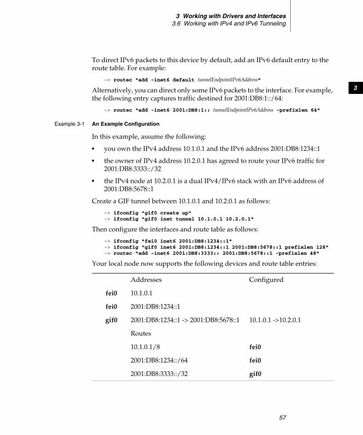
3 Working with Drivers and Interfaces3.6 Working with IPv4 and IPv6 Tunneling
57
3
To direct IPv6 packets to this device by default, add an IPv6 default entry to the route table. For example:
-> routec "add -inet6 default tunnelEndpointIPv6Address"
Alternatively, you can direct only some IPv6 packets to the interface. For example, the following entry captures traffic destined for 2001:DB8:1::/64:
-> routec "add -inet6 2001:DB8:1:: tunnelEndpointIPv6Address -prefixlen 64"
Example 3-1 An Example Configuration
In this example, assume the following:
■ you own the IPv4 address 10.1.0.1 and the IPv6 address 2001:DB8:1234::1
■ the owner of IPv4 address 10.2.0.1 has agreed to route your IPv6 traffic for 2001:DB8:3333::/32
■ the IPv4 node at 10.2.0.1 is a dual IPv4/IPv6 stack with an IPv6 address of 2001:DB8:5678::1
Create a GIF tunnel between 10.1.0.1 and 10.2.0.1 as follows:
-> ifconfig "gif0 create up" -> ifconfig "gif0 inet tunnel 10.1.0.1 10.2.0.1"
Then configure the interfaces and route table as follows:
-> ifconfig "fei0 inet6 2001:DB8:1234::1" -> ifconfig "gif0 inet6 2001:DB8:1234::1 2001:DB8:5678::1 prefixlen 128" -> routec "add -inet6 2001:DB8:3333:: 2001:DB8:5678::1 -prefixlen 48"
Your local node now supports the following devices and route table entries:
Addresses Configured
fei0 10.1.0.1
fei0 2001:DB8:1234::1
gif0 2001:DB8:1234::1 -> 2001:DB8:5678::1 10.1.0.1 ->10.2.0.1
Routes
10.1.0.1/8 fei0
2001:DB8:1234::/64 fei0
2001:DB8:3333::/32 gif0
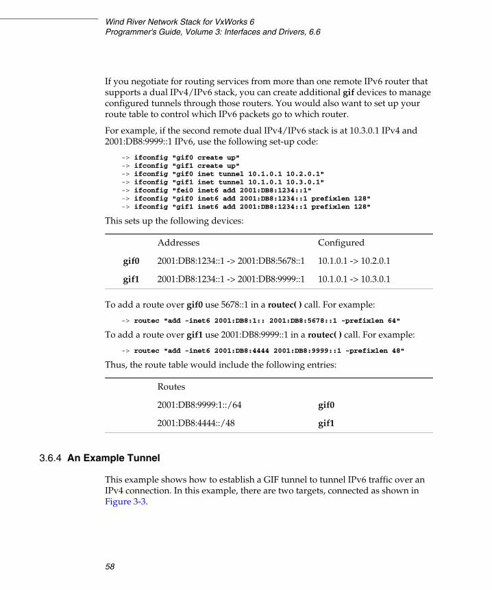
Wind River Network Stack for VxWorks 6Programmer's Guide, Volume 3: Interfaces and Drivers, 6.6
58
If you negotiate for routing services from more than one remote IPv6 router that supports a dual IPv4/IPv6 stack, you can create additional gif devices to manage configured tunnels through those routers. You would also want to set up your route table to control which IPv6 packets go to which router.
For example, if the second remote dual IPv4/IPv6 stack is at 10.3.0.1 IPv4 and 2001:DB8:9999::1 IPv6, use the following set-up code:
-> ifconfig "gif0 create up" -> ifconfig "gif1 create up" -> ifconfig "gif0 inet tunnel 10.1.0.1 10.2.0.1" -> ifconfig "gif1 inet tunnel 10.1.0.1 10.3.0.1" -> ifconfig "fei0 inet6 add 2001:DB8:1234::1" -> ifconfig "gif0 inet6 add 2001:DB8:1234::1 prefixlen 128" -> ifconfig "gif1 inet6 add 2001:DB8:1234::1 prefixlen 128"
This sets up the following devices:
To add a route over gif0 use 5678::1 in a routec( ) call. For example:
-> routec "add -inet6 2001:DB8:1:: 2001:DB8:5678::1 -prefixlen 64"
To add a route over gif1 use 2001:DB8:9999::1 in a routec( ) call. For example:
-> routec "add -inet6 2001:DB8:4444 2001:DB8:9999::1 -prefixlen 48"
Thus, the route table would include the following entries:
3.6.4 An Example Tunnel
This example shows how to establish a GIF tunnel to tunnel IPv6 traffic over an IPv4 connection. In this example, there are two targets, connected as shown in Figure 3-3.
Addresses Configured
gif0 2001:DB8:1234::1 -> 2001:DB8:5678::1 10.1.0.1 -> 10.2.0.1
gif1 2001:DB8:1234::1 -> 2001:DB8:9999::1 10.1.0.1 -> 10.3.0.1
Routes
2001:DB8:9999:1::/64 gif0
2001:DB8:4444::/48 gif1
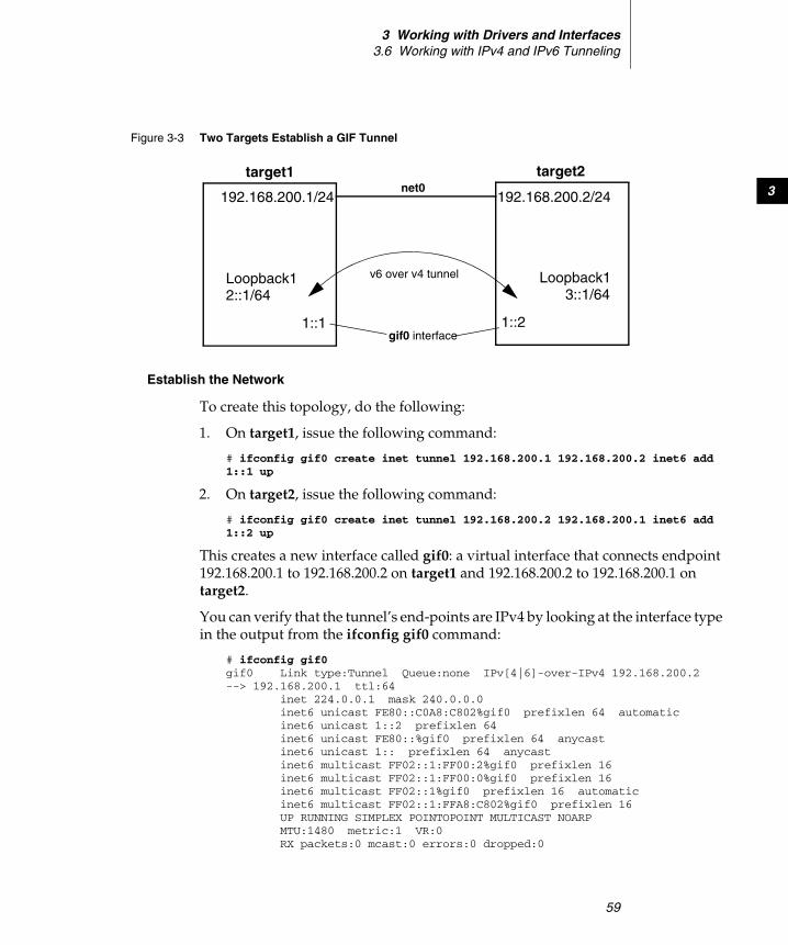
3 Working with Drivers and Interfaces3.6 Working with IPv4 and IPv6 Tunneling
59
3
Establish the Network
To create this topology, do the following:
1. On target1, issue the following command:
# ifconfig gif0 create inet tunnel 192.168.200.1 192.168.200.2 inet6 add 1::1 up
2. On target2, issue the following command:
# ifconfig gif0 create inet tunnel 192.168.200.2 192.168.200.1 inet6 add 1::2 up
This creates a new interface called gif0: a virtual interface that connects endpoint 192.168.200.1 to 192.168.200.2 on target1 and 192.168.200.2 to 192.168.200.1 on target2.
You can verify that the tunnel’s end-points are IPv4 by looking at the interface type in the output from the ifconfig gif0 command:
# ifconfig gif0 gif0 Link type:Tunnel Queue:none IPv[4|6]-over-IPv4 192.168.200.2 --> 192.168.200.1 ttl:64 inet 224.0.0.1 mask 240.0.0.0 inet6 unicast FE80::C0A8:C802%gif0 prefixlen 64 automatic inet6 unicast 1::2 prefixlen 64 inet6 unicast FE80::%gif0 prefixlen 64 anycast inet6 unicast 1:: prefixlen 64 anycast inet6 multicast FF02::1:FF00:2%gif0 prefixlen 16 inet6 multicast FF02::1:FF00:0%gif0 prefixlen 16 inet6 multicast FF02::1%gif0 prefixlen 16 automatic inet6 multicast FF02::1:FFA8:C802%gif0 prefixlen 16 UP RUNNING SIMPLEX POINTOPOINT MULTICAST NOARP MTU:1480 metric:1 VR:0 RX packets:0 mcast:0 errors:0 dropped:0
Figure 3-3 Two Targets Establish a GIF Tunnel
target1
192.168.200.1/24
Loopback12::1/64
1::1
target2
192.168.200.2/24
Loopback13::1/64
1::2gif0 interface
v6 over v4 tunnel
net0
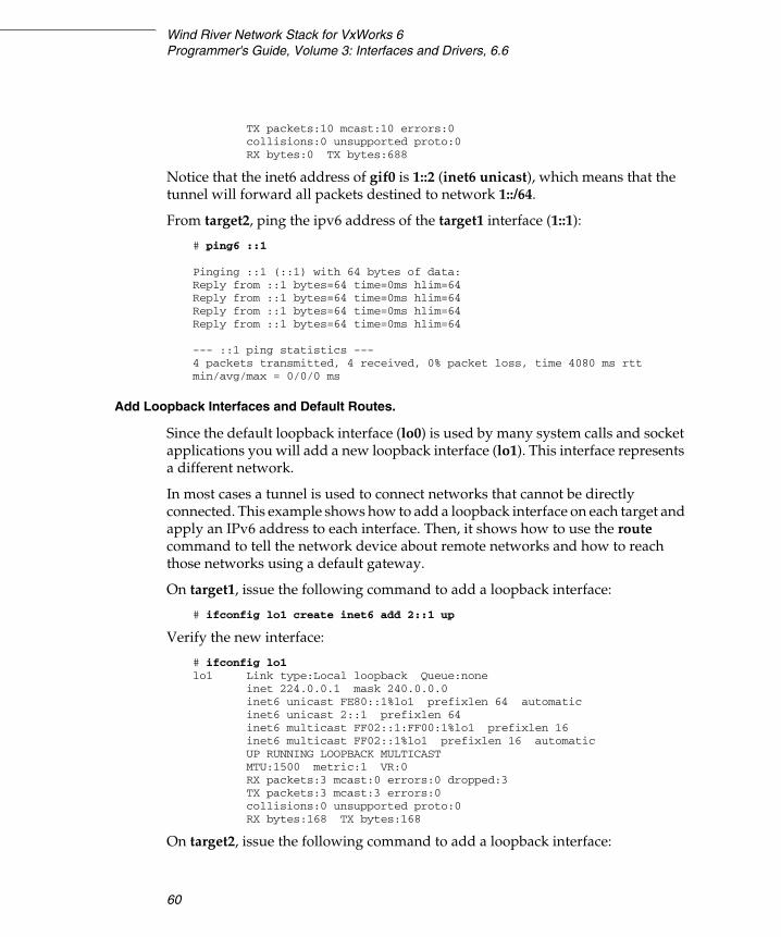
Wind River Network Stack for VxWorks 6Programmer's Guide, Volume 3: Interfaces and Drivers, 6.6
60
TX packets:10 mcast:10 errors:0 collisions:0 unsupported proto:0 RX bytes:0 TX bytes:688
Notice that the inet6 address of gif0 is 1::2 (inet6 unicast), which means that the tunnel will forward all packets destined to network 1::/64.
From target2, ping the ipv6 address of the target1 interface (1::1):
# ping6 ::1
Pinging ::1 (::1) with 64 bytes of data:Reply from ::1 bytes=64 time=0ms hlim=64 Reply from ::1 bytes=64 time=0ms hlim=64 Reply from ::1 bytes=64 time=0ms hlim=64 Reply from ::1 bytes=64 time=0ms hlim=64
--- ::1 ping statistics ---4 packets transmitted, 4 received, 0% packet loss, time 4080 ms rtt min/avg/max = 0/0/0 ms
Add Loopback Interfaces and Default Routes.
Since the default loopback interface (lo0) is used by many system calls and socket applications you will add a new loopback interface (lo1). This interface represents a different network.
In most cases a tunnel is used to connect networks that cannot be directly connected. This example shows how to add a loopback interface on each target and apply an IPv6 address to each interface. Then, it shows how to use the route command to tell the network device about remote networks and how to reach those networks using a default gateway.
On target1, issue the following command to add a loopback interface:
# ifconfig lo1 create inet6 add 2::1 up
Verify the new interface:
# ifconfig lo1 lo1 Link type:Local loopback Queue:none inet 224.0.0.1 mask 240.0.0.0 inet6 unicast FE80::1%lo1 prefixlen 64 automatic inet6 unicast 2::1 prefixlen 64 inet6 multicast FF02::1:FF00:1%lo1 prefixlen 16 inet6 multicast FF02::1%lo1 prefixlen 16 automatic UP RUNNING LOOPBACK MULTICAST MTU:1500 metric:1 VR:0 RX packets:3 mcast:0 errors:0 dropped:3 TX packets:3 mcast:3 errors:0 collisions:0 unsupported proto:0 RX bytes:168 TX bytes:168
On target2, issue the following command to add a loopback interface:

3 Working with Drivers and Interfaces3.6 Working with IPv4 and IPv6 Tunneling
61
3
# ifconfig lo1 create inet6 add 3::1 up
Verify the new interface:
# ifconfig lo1 lo1 Link type:Local loopback Queue:none inet 224.0.0.1 mask 240.0.0.0 inet6 unicast FE80::1%lo1 prefixlen 64 automatic inet6 unicast 3::1 prefixlen 64 inet6 multicast FF02::1:FF00:1%lo1 prefixlen 16 inet6 multicast FF02::1%lo1 prefixlen 16 automatic UP RUNNING LOOPBACK MULTICAST MTU:1500 metric:1 VR:0 RX packets:3 mcast:0 errors:0 dropped:3 TX packets:3 mcast:3 errors:0 collisions:0 unsupported proto:0 RX bytes:168 TX bytes:168
From target2, ping the loopback interface of target1 (2::1/64):
# ping6 2::1 Pinging 2::1 (2::1) with 64 bytes of data:Echo request operation failed: Network is unreachable (51)
You cannot ping interfaces on the network 2::/64 since you do not have a route to that network. Look at the routing table of target2 by issuing the route show command:
# route show
INET route table - vr: 0, table: 254Destination Gateway Flags Use If Metric0.0.0.0/0 192.168.200.254 UGS 0 net0 0127.0.0.0/8 localhost UR 0 lo0 0localhost localhost UH 12 lo0 0192.168.200.0/24 link#2 UC 1 net0 0192.168.200.1 7a:7a:c0:a8:c8:01 UHL 10 net0 1target2 link#1 UH 10 lo0 0
INET6 route table - vr: 0, table: 254Destination Gateway Flags Use If Metric:: link#1 UHRS 0 lo0 0::1 ::1 UH 48 lo0 01::/64 link#4 U 0 gif0 01::2 link#1 UH 0 lo0 03FFE:1:2:3::/64 link#2 UC 0 net0 03FFE:1:2:3::4 link#1 UH 0 lo0 0FE80::%lo0/64 link#1 UC 0 lo0 0FE80::%net0/64 link#2 UC 0 net0 0FE80::%gif0/64 link#4 U 0 gif0 0FE80::1%lo0 link#1 UH 0 lo0 0

Wind River Network Stack for VxWorks 6Programmer's Guide, Volume 3: Interfaces and Drivers, 6.6
62
Or you can use the –inet6 flag to view only IPv6 route configuration:
# route show -inet6
INET6 route table - vr: 0, table: 254Destination Gateway Flags Use If Metric:: link#1 UHRS 0 lo0 0::1 ::1 UH 48 lo0 01::/64 link#4 U 0 gif0 01::2 link#1 UH 0 lo0 03FFE:1:2:3::/64 link#2 UC 0 net0 03FFE:1:2:3::4 link#1 UH 0 lo0 0FE80::%lo0/64 link#1 UC 0 lo0 0FE80::%net0/64 link#2 UC 0 net0 0FE80::%gif0/64 link#4 U 0 gif0 0FE80::1%lo0 link#1 UH 0 lo0 0
Add a Default Gateway
Notice that IPv6 does not have a default gateway (a default gateway is notated by the letter “G” in the flags field). Since we have only one exit point from the device, we can configure the tunnel as a default gateway for any unknown IPv6 destination.
Issue the following command to add a default gateway to target2:
# route add -inet6 default 1::1 add net ::: netmask ::: gateway 1::1
Now, look at the route table again:
# route show -inet6
INET6 route table - vr: 0, table: 254Destination Gateway Flags Use If Metric:: link#1 UHRS 0 lo0 0::/0 1::1 UGS 0 gif0 0::1 ::1 UH 48 lo0 01::/64 link#4 U 0 gif0 01::2 link#1 UH 0 lo0 03FFE:1:2:3::/64 link#2 UC 0 net0 03FFE:1:2:3::4 link#1 UH 0 lo0 0FE80::%lo0/64 link#1 UC 0 lo0 0FE80::%net0/64 link#2 UC 0 net0 0
Add a default gateway to target1:
# route add -inet6 default 1::2 add net ::: netmask ::: gateway 1::2

3 Working with Drivers and Interfaces3.7 Using the Shared-Memory Network
63
3
Test the Tunnel
With a default gateway and a v6-over-v4 tunnel you can ping the loopback interfaces. From target1:
# ping6 3::1 Pinging 3::1 (3::1) with 64 bytes of data:Reply from 3::1 bytes=64 time=0ms hlim=64 Reply from 3::1 bytes=64 time=0ms hlim=64 Reply from 3::1 bytes=64 time=0ms hlim=64 Reply from 3::1 bytes=64 time=0ms hlim=64
--- 3::1 ping statistics ---4 packets transmitted, 4 received, 0% packet loss, time 4080 ms rtt min/avg/max = 0/0/0 ms
This shows ping-v6 packets encapsulated in IPv4 packets and carried from target1 to target2 over an IPv4 link.
3.7 Using the Shared-Memory Network
The smEnd shared-memory network driver allows multiple processors to communicate over their common backplane as if they were communicating over a network, through a MUX-capable network driver.
A multiprocessor backplane bus is an Internet network with its own network / subnet number. Each processor that is a host on this network has its own unique IP address. In the example shown in Figure 3-4, two processors are on a backplane. The Internet address for the shared-memory network is 161.27.0.0. Each processor on the shared-memory network has a unique Internet address, 161.27.0.1 for vx1 and 161.27.0.2 for vx2.

Wind River Network Stack for VxWorks 6Programmer's Guide, Volume 3: Interfaces and Drivers, 6.6
64
Processors can communicate with other processors on the same backplane by means of an instance of the smEnd driver. This driver behaves as any other network driver, and so a variety of network services may communicate through it.
3.7.1 The Backplane Shared-Memory Region
This simulation of driver communication takes place in a contiguous memory region that all processors on the backplane can access through instantiations of the smEnd driver.1
Backplane Processor Numbers
Assign each processor on the backplane a unique backplane processor number starting with 0. With the exception of processor #0, which by convention and by default is the shared-memory network master (described below), these numbers are arbitrary and you may set them to whatever you find convenient.
Set the processor numbers in the boot-line parameters that you pass to the boot image. You can burn these parameters into ROM, set them in the processor’s NVRAM (if available), or enter them manually.
Figure 3-4 Shared-Memory Network
Backplane
161.27.0.1 161.27.0.2
161.27.0.0
vx1 vx2
1. The backplane is a type of bus. In this document, the terms “backplane” and “bus” are used interchangeably.

3 Working with Drivers and Interfaces3.7 Using the Shared-Memory Network
65
3
The Shared-Memory Network Master
One processor on the backplane is the shared-memory network master. The shared-memory network master has the following responsibilities:
■ Initialize the shared-memory region and the shared-memory anchor.
■ Maintain the shared-memory heartbeat.
■ Function (usually) as the gateway to the external network.
■ Allocate the shared-memory region (on some boards the master statically reserves the shared-memory region; on others it allocates this region from the kernel heap).
No processor can use the shared-memory network until the shared-memory network master initializes it. However, the master processor is not involved in the actual transmission of packets on the backplane between other processors. After the shared-memory network master initializes the shared-memory region, all of the processors, including the master, are peers.
Set the processor number of the master with the shared memory master CPU number (SM_MASTER) build configuration parameter. A node that knows the master node’s processor number can determine at run time whether it is the master node by comparing this processor number with the one that you assigned to the node in the boot parameters.
Typically, the master boots from the external network directly. The master has two Internet addresses in the system: its Internet address on the external network, and its address on the shared-memory network. (See the reference entry for usrConfig.)
NOTE: You can set up two shared memory networks on a single backplane with the smEnd driver, with a single processor acting as a node on each of the two networks. However, if you use VxMP, you can set up only one shared memory network over the backplane. In this case, the processor number of the master node is zero.
NOTE: You configure the maximum number of processors at build time with the max # of cpus for shared network (SM_CPUS_MAX) configuration parameter. The largest processor number that you can use is one less than this total maximum processor count.
Wind River Network Stack for VxWorks 6Programmer's Guide, Volume 3: Interfaces and Drivers, 6.6
66
The other processors on the backplane can boot indirectly over the shared-memory network, using the master as the gateway. They need only have an Internet address on the shared-memory network. These processors specify the shared-memory network interface, sm, as the boot device in the boot parameters.
For more information and an example, see 3.7.4 Shared-Memory Network Configuration, p.73.
The Shared-Memory Anchor
The location of the shared-memory region depends on the system configuration. All processors on the shared-memory network must be able to access the shared-memory region within the same bus address space as the anchor.
The shared-memory anchor serves as a common point of reference for all processors. You may place the anchor structure and the shared-memory region in the dual-ported memory of one of the participating boards (the master by default) or in the memory of a separate memory board.
The anchor contains an offset to the actual shared-memory region. The master sets this value during initialization. The offset is relative to the anchor itself. Thus, the anchor and pool must be in the same address space so that the offset is valid for all processors.
Set the anchor bus address by setting configuration parameters or by setting boot parameters. For the shared-memory network master, you assign the anchor bus address in the master’s configuration at the time you build the system image.
Set the shared-memory anchor bus address, as seen by the master, during configuration with the configuration parameter SM_ANCHOR_ADRS.
For the other processors on the shared-memory network, you can assign a default anchor bus address during configuration in the same way. However, this requires that you burn boot ROMs with that configuration, because the other processors must, at first, boot from the shared-memory network. For this reason, you can specify the anchor bus address in the boot parameters if the shared-memory backplane network interface is the boot device.
NOTE: Some BSPs allow you to put the anchor and shared-memory regions on a participating non-master board. For examples of how to do this, see the compact PCI bus BSPs mcp750 and mcpn750.

3 Working with Drivers and Interfaces3.7 Using the Shared-Memory Network
67
3
The format of the boot line is bootDeviceName=localAddress. For example:
sm=0x10010000
This is the address of the anchor as seen by the processor you are booting.
The Shared-Memory Heartbeat
The processors on the shared-memory network cannot communicate over that network until the shared-memory network master finishes initializing the shared-memory region. To let the other processors know when the backplane is “alive,” the master maintains a shared-memory heartbeat. This heartbeat is a counter that the master increments once per second. Processors on the shared-memory network determine that the shared-memory network is alive by watching the heartbeat for a few seconds.
The shared-memory heartbeat is located in the first 4-byte word of the shared-memory packet header. The offset of the shared-memory packet header is the fifth 4-byte word in the anchor, as shown in Figure 3-5.
Shared-Memory Location
The compiler puts the shared-memory region in a fixed location with a fixed size. You set this location with the SM_MEM_ADRS parameter in the INCLDUE_SM_COMMON component for that board. Because all processors on the backplane access the shared-memory region, you must configure that memory as non-cacheable or use a cache coherency mechanism.
Figure 3-5 Shared-Memory Heartbeat
~~ ~~
1. ready value2. .3. .4. .5. Offset for smPktHeader
heartbeat
Shared-MemoryAnchor
smPktHeader(anchor + offset)
Wind River Network Stack for VxWorks 6Programmer's Guide, Volume 3: Interfaces and Drivers, 6.6
68
The shared-memory region (not including the anchor) can also be allocated at run time if you set SM_MEM_ADRS to NONE. In this case, a region of size SM_MEM_SIZE is allocated and made non-cacheable. If used this way, be wary that shared memory is allocated from the kernel heap. The whole heap must thus be mapped on the backplane.
Shared Memory Size
Set the size of the shared-memory network area by setting the build configuration parameter SM_MEM_SIZE. A related area, the shared-memory object area, used by VxMP, is governed by the configuration parameter SM_OBJ_MEM_SIZE.
The size you will need for the shared-memory network area depends on the number of processors and on how much traffic you expect. There is less than 2KB of overhead for data structures. After that, the shared-memory network area is divided into 2KB packets. Thus, the maximum number of packets available on the backplane network is (areaSize – 2KB) / 2KB. A reasonable minimum is 64KB. A configuration with a large number of processors on one backplane and many simultaneous connections can require as much as 512KB. If you reserve a backplane network memory area that is too small, you will slow network communication.
Test-and-Set to Shared Memory
To prevent more than one processor from simultaneously accessing certain critical data structures of the shared-memory region, the smEnd driver uses an indivisible test-and-set (TAS) instruction to obtain exclusive use of a shared-memory data structure. This translates into a read-modify-write (RMW) cycle on the backplane bus.2
The selected shared memory must support the RMW cycle on the bus and must guarantee the indivisibility of such cycles. This can be problematic if the memory is dual-ported (that is it resides on the master and can be accessed there as local RAM, while existing also as shared memory on the bus accessible by the slave
2. Or a close approximation to it. Some hardware cannot generate RMW cycles on the VME bus and the PCI bus does not support them at all.
NOTE: The shared-memory network driver does not support the specification of TAS operation size. This size is architecture dependent.

3 Working with Drivers and Interfaces3.7 Using the Shared-Memory Network
69
3
boards), as the memory must then lock out one port during a RMW cycle on the other.
Some processors do not support RMW indivisibly in hardware, but do have software hooks to provide the capability. For example, some processor boards have a flag that you can set to prevent the board from releasing the backplane bus, after you acquire the flag, until you clear that flag. You can implement this test-and-set technique for a processor in the sysBusTas( ) routine of the system-dependent library sysLib. The smEnd driver calls this routine to set up mutual exclusion on shared-memory data structures.
3.7.2 Interprocessor Interrupts
Each processor on the backplane has a single input queue for packets that it receives from other processors. To attend to its input queue, a processor can either poll or rely on interrupts (either bus interrupts or mailbox interrupts). When polling, the processor examines its input queue at fixed intervals. When using interrupts, the sending processor notifies the receiving processor that the receiving processor’s input queue contains packets.
Processors that communicate by means of either bus interrupts or mailbox interrupts are more efficient than those that use polling because they invest fewer cycles in communication (although at a cost of greater latency). Unfortunately, the bus interrupt mechanism can handle only as many processors as there are interrupt lines available on the backplane (for example, VMEbus has seven). In addition, not all processor boards are capable of generating bus interrupts.
As an alternative to bus interrupts, you can use mailbox interrupts, also called location monitors because they monitor the access to specific memory locations. A mailbox interrupt specifies a bus address that, when a processor writes to it or reads from it, causes a specific interrupt on the processor board. You can set hardware jumpers or software registers to set each board to use a different address for its mailbox interrupt.
To generate a mailbox interrupt, a processor accesses the specified mailbox address and performs a configurable read or write of a configurable size. Because each interrupt requires only a single address on the bus, there is effectively no limit
! CAUTION: Configure the shared-memory test-and-set type (configuration parameter: SM_TAS_TYPE) to either SM_TAS_SOFT or SM_TAS_HARD. If even one processor on the backplane lacks hardware test-and-set, you must configure all processors in the backplane to use software test-and-set (SM_TAS_SOFT).
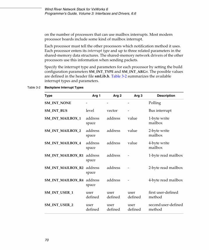
Wind River Network Stack for VxWorks 6Programmer's Guide, Volume 3: Interfaces and Drivers, 6.6
70
on the number of processors that can use mailbox interrupts. Most modern processor boards include some kind of mailbox interrupt.
Each processor must tell the other processors which notification method it uses. Each processor enters its interrupt type and up to three related parameters in the shared-memory data structures. The shared-memory network drivers of the other processors use this information when sending packets.
Specify the interrupt type and parameters for each processor by setting the build configuration parameters SM_INT_TYPE and SM_INT_ARGn. The possible values are defined in the header file smLib.h. Table 3-2 summarizes the available interrupt types and parameters.
Table 3-2 Backplane Interrupt Types
Type Arg 1 Arg 2 Arg 3 Description
SM_INT_NONE - - - Polling
SM_INT_BUS level vector - Bus interrupt
SM_INT_MAILBOX_1 address space
address value 1-byte write mailbox
SM_INT_MAILBOX_2 address space
address value 2-byte write mailbox
SM_INT_MAILBOX_4 address space
address value 4-byte write mailbox
SM_INT_MAILBOX_R1 address space
address - 1-byte read mailbox
SM_INT_MAILBOX_R2 address space
address - 2-byte read mailbox
SM_INT_MAILBOX_R4 address space
address - 4-byte read mailbox
SM_INT_USER_1 user defined
user defined
user defined
first user-defined method
SM_INT_USER_2 user defined
user defined
user defined
second user-defined method
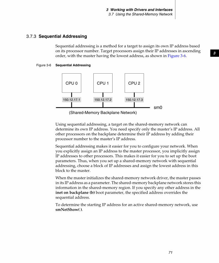
3 Working with Drivers and Interfaces3.7 Using the Shared-Memory Network
71
3
3.7.3 Sequential Addressing
Sequential addressing is a method for a target to assign its own IP address based on its processor number. Target processors assign their IP addresses in ascending order, with the master having the lowest address, as shown in Figure 3-6.
Using sequential addressing, a target on the shared-memory network can determine its own IP address. You need specify only the master’s IP address. All other processors on the backplane determine their IP address by adding their processor number to the master’s IP address.
Sequential addressing makes it easier for you to configure your network. When you explicitly assign an IP address to the master processor, you implicitly assign IP addresses to other processors. This makes it easier for you to set up the boot parameters. Thus, when you set up a shared-memory network with sequential addressing, choose a block of IP addresses and assign the lowest address in this block to the master.
When the master initializes the shared-memory network driver, the master passes in its IP address as a parameter. The shared-memory backplane network stores this information in the shared-memory region. If you specify any other address in the inet on backplane (b) boot parameter, the specified address overrides the sequential address.
To determine the starting IP address for an active shared-memory network, use smNetShow( ).
Figure 3-6 Sequential Addressing
150.12.17.1 150.12.17.2 150.12.17.3
(Shared-Memory Backplane Network)sm0
CPU 0 CPU 1 CPU 2
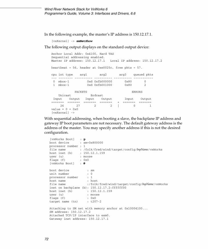
Wind River Network Stack for VxWorks 6Programmer's Guide, Volume 3: Interfaces and Drivers, 6.6
72
In the following example, the master’s IP address is 150.12.17.1.
[vxKernel] -> smNetShow
The following output displays on the standard output device:
Anchor Local Addr: 0x4100, Hard TASSequential addressing enabled.Master IP address: 150.12.17.1 Local IP address: 150.12.17.2
heartbeat = 56, header at 0xe0025c, free pkts = 57.
cpu int type arg1 arg2 arg3 queued pkts--- -------- ---------- ---------- ---------- -----------0 mbox-1 0xd 0xfb000000 0x80 01 mbox-1 0xd 0xfb001000 0x80 2
PACKETS ERRORSUnicast Brdcast
Input Output Input Output Input Output======= ======= ======= ======= + ======= =======
26 27 2 2 | 0 1value = 0 = 0x0[vxKernel] ->
With sequential addressing, when booting a slave, the backplane IP address and gateway IP boot parameters are not necessary. The default gateway address is the address of the master. You may specify another address if this is not the desired configuration.
[vxWorks Boot] : pboot device : sm=0x800000processor number : 1file name : /folk/fred/wind/target/config/bspName/vxWorkshost inet (h) : 150.12.1.159user (u) : mooseflags (f) : 0x0[vxWorks Boot] : @
boot device : smunit number : 0processor number : 1host name : hostfile name :/folk/fred/wind/target/config/bspName/vxWorksinet on backplane (b): 150.12.17.2:ffffff00host inet (h) : 150.12.1.159user (u) : mooseflags (f) : 0x0target name (tn) : t207-2
Attaching to SM net with memory anchor at 0x10004100...SM address: 150.12.17.2Attached TCP/IP interface to esm0.Gateway inet address: 150.12.17.1

3 Working with Drivers and Interfaces3.7 Using the Shared-Memory Network
73
3
Attaching interface lo0...doneLoading /folk/fred/wind/target/config/bspName/vxWorks/boot.txt
sdm0=/folk/fred/wind/target/config/bspName/vxWorks/vxKernel.sdm0x000d8ae0 + 0x00018cf0 + 0x00011f70 + (0x0000ccec) + 0x00000078 + 0x0000015c
You enable sequential addressing during configuration. The relevant component is INCLUDE_SM_SEQ_ADDR.
3.7.4 Shared-Memory Network Configuration
For UNIX, configure the host to support a shared-memory network with the same process outlined elsewhere for other types of networks. In particular, a shared-memory backplane network requires the following:
■ That you have put all shared-memory network host names and addresses in /etc/hosts.
■ That you have put all shared-memory network host names in .rhosts in your home directory or in /etc/hosts.equiv if you are using RSH.
■ That you have put an entry in the host’s routing table that specifies the master’s Internet address on the external network as the gateway to the shared-memory backplane network.
■ That you have turned on the IP forwarding parameter on the node functioning as gateway.
For Windows hosts, the steps required to configure the host are determined by your version of Windows and the networking software you are using. See that documentation for details.
Example Configuration
This section presents an example of a simple shared-memory network. The network contains a single host and two target processors on a single backplane. In addition to the target processors, the backplane includes a separate memory board for the shared-memory region, and an Ethernet controller board. The additional memory board is not essential, but provides a configuration that is easier to describe.
Figure 3-7 illustrates the overall configuration. The Ethernet network is assigned network number 150, subnet 12.0, and the shared-memory backplane network is

Wind River Network Stack for VxWorks 6Programmer's Guide, Volume 3: Interfaces and Drivers, 6.6
74
assigned network number 161, subnet 27.0. The host h1 is assigned the Internet address 150.12.0.1.
The shared-memory master is vx1, and functions as the gateway between the Ethernet and shared-memory networks. It therefore has two Internet addresses: 150.12.0.2 on the Ethernet network and 161.27.0.1 on the shared-memory network.
The other backplane processor is vx2; it has the shared-memory network address 161.27.0.2. It has no address on the Ethernet because it is not directly connected to that network. However, it can communicate with h1 over the shared-memory network, using vx1 as a gateway. All gateway use is handled by the IP layer and is completely transparent to the user. Table 3-3 shows the example address assignments.
Figure 3-7 Example Shared-Memory Network
Ethernet
h1
vx1vx2
host
sm master& gateway
150.12.0.0
150.12.0.1
150.12.0.2
161.27.0.1161.27.0.2
161.27.0.0Shared-MemoryNetwork
Table 3-3 Network Address Assignments
Name inet on Ethernet inet on Backplane
h1 150.12.0.1 —
vx1 150.12.0.2 161.27.0.1
vx2 — 161.27.0.2
3 Working with Drivers and Interfaces3.7 Using the Shared-Memory Network
75
3
To configure the UNIX system for our example, you must add the Internet address and name of each system to the /etc/hosts file. Note that the backplane master has two entries. The second entry, vx1.sm, is not actually necessary because the host system never accesses that system with that address, but you should include it in the file to ensure that some other device does not use the address.
The entries in /etc/hosts are as follows:
150.12.0.1 h1150.12.0.2 vx1161.27.0.1 vx1.sm161.27.0.2 vx2
To allow remote access from the target systems to the UNIX host, add the names of the target systems to the .rhosts file in your home directory (or to the file /etc/hosts.equiv):
vx1vx2
To inform the UNIX system of the existence of the Ethernet-to-shared-memory network gateway, add the following line to the file /etc/gateways before you start the route daemon routed.
net 161.27.0.0 gateway 150.12.0.2 metric 1 passive
Alternatively, you can add the route manually (effective until the next reboot) with the following UNIX command:
% route add net 161.27.0.0 150.12.0.2 1
To prepare a run-time image for vx1, the backplane master shown in Figure 3-7, include the following configuration components:
■ INCLUDE_SM_NET – includes the shared memory network
■ INCLUDE_SM_COMMON – includes configuration parameters common to memory sharing utilities
■ INCLUDE_SM_NET_SHOW – includes the smNetShow( ) routine
Within these components, you can set the parameters as shown in Table 3-4.
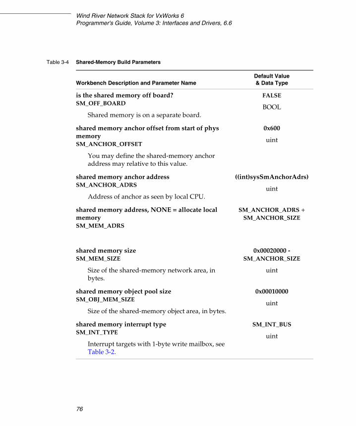
Wind River Network Stack for VxWorks 6Programmer's Guide, Volume 3: Interfaces and Drivers, 6.6
76
Table 3-4 Shared-Memory Build Parameters
Workbench Description and Parameter NameDefault Value& Data Type
is the shared memory off board?SM_OFF_BOARD
Shared memory is on a separate board.
FALSE
BOOL
shared memory anchor offset from start of phys memory SM_ANCHOR_OFFSET
You may define the shared-memory anchor address may relative to this value.
0x600
uint
shared memory anchor addressSM_ANCHOR_ADRS
Address of anchor as seen by local CPU.
((int)sysSmAnchorAdrs)
uint
shared memory address, NONE = allocate local memory SM_MEM_ADRS
SM_ANCHOR_ADRS + SM_ANCHOR_SIZE
shared memory sizeSM_MEM_SIZE
Size of the shared-memory network area, in bytes.
0x00020000 - SM_ANCHOR_SIZE
uint
shared memory object pool sizeSM_OBJ_MEM_SIZE
Size of the shared-memory object area, in bytes.
0x00010000
uint
shared memory interrupt type SM_INT_TYPE
Interrupt targets with 1-byte write mailbox, see Table 3-2.
SM_INT_BUS
uint
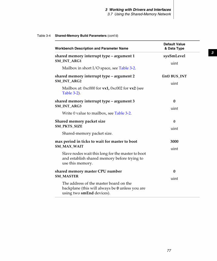
3 Working with Drivers and Interfaces3.7 Using the Shared-Memory Network
77
3shared memory interrupt type – argument 1 SM_INT_ARG1
Mailbox in short I/O space, see Table 3-2.
sysSmLevel
uint
shared memory interrupt type – argument 2SM_INT_ARG2
Mailbox at: 0xc000 for vx1, 0xc002 for vx2 (see Table 3-2).
(int) BUS_INT
uint
shared memory interrupt type – argument 3SM_INT_ARG3
Write 0 value to mailbox, see Table 3-2.
0
uint
Shared memory packet size SM_PKTS_SIZE
Shared-memory packet size.
0
uint
max period in ticks to wait for master to boot SM_MAX_WAIT
Slave nodes wait this long for the master to boot and establish shared memory before trying to use this memory.
3000
uint
shared memory master CPU number SM_MASTER
The address of the master board on the backplane (this will always be 0 unless you are using two smEnd devices).
0
uint
Table 3-4 Shared-Memory Build Parameters (cont’d)
Workbench Description and Parameter NameDefault Value& Data Type
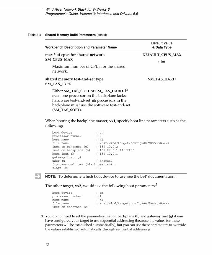
Wind River Network Stack for VxWorks 6Programmer's Guide, Volume 3: Interfaces and Drivers, 6.6
78
When booting the backplane master, vx1, specify boot line parameters such as the following:
boot device : gnprocessor number : 0host name : h1file name : /usr/wind/target/config/bspName/vxWorksinet on ethernet (e) : 150.12.0.2inet on backplane (b) : 161.27.0.1:ffffff00host inet (h) : 150.12.0.1gateway inet (g) :user (u) : thoreauftp password (pw) (blank=use rsh) :flags (f) : 0
The other target, vx2, would use the following boot parameters:3
boot device : smprocessor number : 1host name : h1file name : /usr/wind/target/config/bspName/vxWorksinet on ethernet (e) :
max # of cpus for shared network SM_CPUS_MAX
Maximum number of CPUs for the shared network.
DEFAULT_CPUS_MAX
uint
shared memory test-and-set type SM_TAS_TYPE
Either SM_TAS_SOFT or SM_TAS_HARD. If even one processor on the backplane lacks hardware test-and-set, all processors in the backplane must use the software test-and-set (SM_TAS_SOFT).
SM_TAS_HARD
Table 3-4 Shared-Memory Build Parameters (cont’d)
Workbench Description and Parameter NameDefault Value& Data Type
NOTE: To determine which boot device to use, see the BSP documentation.
3. You do not need to set the parameters inet on backplane (b) and gateway inet (g) if you have configured your target to use sequential addressing (because the values for these parameters will be established automatically), but you can use these parameters to override the values established automatically through sequential addressing.

3 Working with Drivers and Interfaces3.7 Using the Shared-Memory Network
79
3
inet on backplane (b) : 161.27.0.2host inet (h) : 150.12.0.1gateway inet (g) : 161.27.0.1user (u) : thoreauftp password (pw) (blank=use rsh)†:flags (f) : 0
Troubleshooting
Getting a shared-memory network configured for the first time can be tricky. If you have trouble, use the following troubleshooting procedures—taking one step at a time:
1. Boot a single processor in the backplane without any additional memory or processor cards.
2. Power off and add the memory board, if you are using one. Power on and boot the system again. Using the boot ROM commands for display memory (d) and modify memory (m), verify that you can access the shared memory at the address you expect, with the size you expect.
3. Rebuild the system and manually fill in the inet on backplane boot parameter (do not rely on sequential addressing). This initializes the shared-memory network. The following message appears during the reboot:
Backplane anchor at anchorAddress...Attaching network interface sm...done.
4. After the system boots, display the state of the shared-memory network with the smNetShow( ) routine, as follows:
-> smNetShow ["interfaceName"] [, 1]value = 0 = 0x0
The interface parameter is sm by default. Normally, smNetShow( ) displays cumulative activity statistics to the standard output device; specifying 1 (one) as the second argument resets the totals to zero.
5. Test the host connection to the shared-memory master by pinging both of its IP addresses from the host. On the host console, type:
ping 150.12.0.2
This should succeed and produce a message something like:
150.12.0.2 is alive
Then type:
ping 161.27.0.1
Wind River Network Stack for VxWorks 6Programmer's Guide, Volume 3: Interfaces and Drivers, 6.6
80
This should also succeed. If either ping fails, the host is not configured properly, or the shared-memory master has incorrect boot parameters.
6. Power off and add the second processor board. Do not configure the second processor as the system controller board. Power on and stop the second processor from booting by typing any key to the boot ROM program. Boot the first processor as you did before.
7. If you have trouble booting the first processor with the second processor plugged in, you have some hardware conflict. Check that only the first processor board is the system controller. Check that there are no conflicts between the memory addresses of the various boards.
8. On the second processor’s console, use the d and m boot ROM commands to verify that you can see the shared memory from the second processor. This is either the memory of the separate memory board (if you are using the off-board configuration) or the dual-ported memory of the first processor (if you are using the on-board configuration).
9. Use the d command on the second processor to look for the two-part shared-memory anchor (bus address space and anchor location within that space). You can also look for the shared-memory heartbeat; see The Shared-Memory Heartbeat, p.67.
10. After you have found the anchor from the second processor, enter the boot parameter for the boot device with that two-part anchor bus address:
boot device: sm=0x10010000
Enter the other boot parameters and try booting the second processor.
11. If the second processor does not boot, you can use smNetShow( ) on the first processor to see if the second processor is correctly attaching to the shared-memory network. If not, then you have probably specified the anchor bus address incorrectly on the second processor or have a mapping error between the local and backplane buses. If the second processor is attached, then the problem is more likely to be with the gateway or with the host system configuration.
12. You can use host system utilities, such as arp, netstat, and ping, to study the state of the network from the host side.
13. If all else fails, call your technical support organization.
81
4Integrating a New Network
Interface Driver
4.1 Introduction 82
4.2 Configuring VxWorks for Network Interface Drivers 86
4.3 How VxWorks Launches and Uses Your Driver 87
4.4 Driver Components 93
4.5 Transmitting Data 95
4.6 Implementing Checksum Offloading 102
4.7 Implementing a Network Driver 108
4.8 The Driver Interface with the MUX 128
4.9 Porting a BSD Driver to the MUX 159
4.10 Managing Memory for Network Drivers and Services 162
4.11 Collecting and Reporting Packet Statistics 175

Wind River Network Stack for VxWorks 6Programmer's Guide, Volume 3: Interfaces and Drivers, 6.6
82
4.1 Introduction
This chapter describes how to write a new network interface driver and integrate it into the Wind River Network Stack.
For this, you write your driver to use the MUX. This includes using an set of routines that the MUX provides, and implementing a set of routines that the MUX uses.
The MUX interface insulates network services from the particulars of network interface drivers, and vice versa. The MUX supports two network driver styles, the Enhanced Network Driver (END) and the Network Protocol Toolkit (NPT) driver:
■ ENDs
ENDs are frame-oriented drivers that exchange link-layer frames with the MUX. Currently, all network drivers supplied by Wind River are ENDs, as is the generic network driver template defined in templateVxbEnd.c.
■ NPT Drivers
NPT drivers are packet-oriented drivers that exchange network-layer packets with the MUX, stripping these packets of data link layer headers first. There is no generic template for an NPT driver.
4.1.1 How ENDs and NPT Drivers Differ
An NPT driver is a packet-oriented, an END is frame-oriented. Both are organized around the END_OBJ and the NET_FUNCS structures, and both driver styles require many of the same entry points (see Figure 4-1):
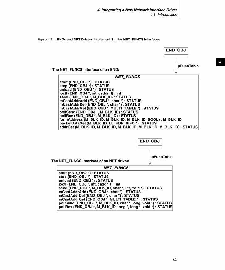
4 Integrating a New Network Interface Driver4.1 Introduction
83
4
Figure 4-1 ENDs and NPT Drivers Implement Similar NET_FUNCS Interfaces
NET_FUNCSstart (END_OBJ *) : STATUSstop (END_OBJ *) : STATUSunload (END_OBJ *) : STATUSioctl (END_OBJ *, int, caddr_t) : intsend (END_OBJ *, M_BLK_ID) : STATUSmCastAddrAdd (END_OBJ *, char *) : STATUSmCastAddrDel (END_OBJ *, char *) : STATUSmCastAddrGet (END_OBJ *, MULTI_TABLE *) : STATUSpollSend (END_OBJ *, M_BLK_ID) : STATUSpollRcv (END_OBJ *, M_BLK_ID) : STATUSformAddress (M_BLK_ID, M_BLK_ID, M_BLK_ID, BOOL) : M_BLK_IDpacketDataGet (M_BLK_ID, LL_HDR_INFO *) : STATUSaddrGet (M_BLK_ID, M_BLK_ID, M_BLK_ID, M_BLK_ID, M_BLK_ID) : STATUS
NET_FUNCSstart (END_OBJ *) : STATUSstop (END_OBJ *) : STATUSunload (END_OBJ *) : STATUSioctl (END_OBJ *, int, caddr_t) : intsend (END_OBJ *, M_BLK_ID, char *, int, void *) : STATUSmCastAddrAdd (END_OBJ *, char *) : STATUSmCastAddrDel (END_OBJ *, char *) : STATUSmCastAddrGet (END_OBJ *, MULTI_TABLE *) : STATUSpollSend (END_OBJ *, M_BLK_ID, char *, long, void *) : STATUSpollRcv (END_OBJ *, M_BLK_ID, long *, long *, void *) : STATUS
END_OBJ
pFuncTable
END_OBJ
pFuncTableThe NET_FUNCS interface of an END:
The NET_FUNCS interface of an NPT driver:
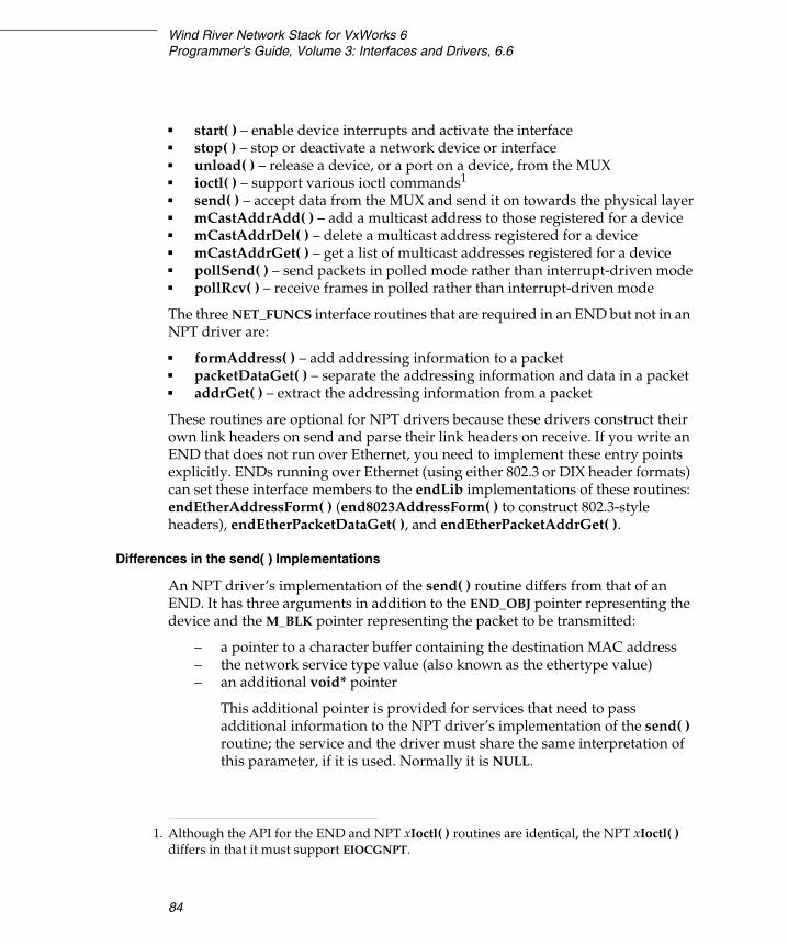
Wind River Network Stack for VxWorks 6Programmer's Guide, Volume 3: Interfaces and Drivers, 6.6
84
■ start( ) – enable device interrupts and activate the interface■ stop( ) – stop or deactivate a network device or interface■ unload( ) – release a device, or a port on a device, from the MUX■ ioctl( ) – support various ioctl commands1
■ send( ) – accept data from the MUX and send it on towards the physical layer■ mCastAddrAdd( ) – add a multicast address to those registered for a device■ mCastAddrDel( ) – delete a multicast address registered for a device■ mCastAddrGet( ) – get a list of multicast addresses registered for a device■ pollSend( ) – send packets in polled mode rather than interrupt-driven mode■ pollRcv( ) – receive frames in polled rather than interrupt-driven mode
The three NET_FUNCS interface routines that are required in an END but not in an NPT driver are:
■ formAddress( ) – add addressing information to a packet■ packetDataGet( ) – separate the addressing information and data in a packet■ addrGet( ) – extract the addressing information from a packet
These routines are optional for NPT drivers because these drivers construct their own link headers on send and parse their link headers on receive. If you write an END that does not run over Ethernet, you need to implement these entry points explicitly. ENDs running over Ethernet (using either 802.3 or DIX header formats) can set these interface members to the endLib implementations of these routines: endEtherAddressForm( ) (end8023AddressForm( ) to construct 802.3-style headers), endEtherPacketDataGet( ), and endEtherPacketAddrGet( ).
Differences in the send( ) Implementations
An NPT driver’s implementation of the send( ) routine differs from that of an END. It has three arguments in addition to the END_OBJ pointer representing the device and the M_BLK pointer representing the packet to be transmitted:
– a pointer to a character buffer containing the destination MAC address– the network service type value (also known as the ethertype value)– an additional void* pointer
This additional pointer is provided for services that need to pass additional information to the NPT driver’s implementation of the send( ) routine; the service and the driver must share the same interpretation of this parameter, if it is used. Normally it is NULL.
1. Although the API for the END and NPT xIoctl( ) routines are identical, the NPT xIoctl( ) differs in that it must support EIOCGNPT.
4 Integrating a New Network Interface Driver4.1 Introduction
85
4
An NPT driver’s implementation of the send( ) routine must create a MAC header by using the destination MAC address and network service type that the MUX passes in to the routine, and its own source MAC address, and prepend this MAC header to the frame. However, if the destination MAC address pointer that the MUX passes into this routine is NULL, a complete MAC header is already prepended to the frame and the NPT driver must not add another one.
Differences in MUX Receive Routines
During the muxDevLoad( ) call, the MUX sets the receiveRtn member of the device’s END_OBJ-derived DRV_CTRL structure to point to the routine that the device should call to pass received data up the stack. ENDs and NPT drivers call this routine differently:
The receiveRtn Called by an END
An END calls this routine with two parameters, as follows:
device->receiveRtn ( device, packet );
device the END_OBJ pointer that describes the device that is calling the routine
packet an M_BLK pointer that describes the packet being received.
The header file endLib.h has a macro, END_RCV_RTN_CALL( ), that the driver may use (if it wishes) to call the MUX receive routine.
The receiveRtn Called by an NPT Driver
The NPT driver parses the link header and passes enough information to the MUX (and thereby to network service receive routines) to let them strip the link header from the frame. The NPT driver itself does not remove the link header.
An NPT driver calls this routine with six parameters, as follows:
device->receiveRtn ( device, frame, offset, type, cast, extra );
device the END_OBJ pointer that describes the device that is calling the routine
frame an M_BLK pointer that describes the frame being received.
offset the offset from the start of the frame to the network-layer header—this is called the network service offset, and is the same as the link header size
Wind River Network Stack for VxWorks 6Programmer's Guide, Volume 3: Interfaces and Drivers, 6.6
86
type the network service type value (ethertype value)
cast a boolean value that the driver should set to TRUE if it is in promiscuous mode when it makes this call, and it has received a unicast or multicast packet that is not intended for this device—so that the MUX only passes this frame to SNARF or PROMISCUOUS services
Setting this value to TRUE is merely an optimization; network services must check that they are the intended recipient of the packet in any case. So it is recommended that you only set this value to TRUE if the driver has a quick way (such as a bit in the receive descriptor) to identify packets that would not be received were the device not in promiscuous mode.
extra an extra void * pointer to a buffer that contains any additional information that should be passed to the receiving service—the service and the driver must agree on the interpretation of this value (most services ignore it, and most drivers pass NULL)
The header file endLib.h has a macro, TK_RCV_RTN_CALL( ), that the driver may use (if it wishes) to call the MUX receive routine.
4.2 Configuring VxWorks for Network Interface Drivers
The Wind River Network Stack requires the following configuration components in order to use the MUX to implement network interface drivers:
■ END interface support (INCLUDE_END)■ MUX support (INCLUDE_MUX)
END interface support
The INCLUDE_END component pulls in endLib, which provides support for ENDs and NPT drivers running under the MUX. For this reason, this component also requires INCLUDE_MUX.
The endLib library also includes functionality that provides common support routines used by all ENDs and NPT drivers. It also contains some functionality specifically designed for use in drivers running over Ethernet.

4 Integrating a New Network Interface Driver4.3 How VxWorks Launches and Uses Your Driver
87
4
MUX support
The INCLUDE_MUX component pulls in support for the MUX interface, implemented in the muxLib and muxTkLib libraries. For more information on these libraries, see the muxLib and muxTkLib reference entries.
4.3 How VxWorks Launches and Uses Your Driver
The task tUsrRoot is the first task started during system boot. It initializes all portions of the operating system, including the network stack. Part of network stack initialization consists of initializing at least one network job queue, and spawning a task (such as tNet0) to process items on each network job queue.
To load your network device into the MUX, tUsrRoot calls muxDevLoad( ). As input to the call, tUsrRoot specifies your driver’s xLoad( ) entry point, and the muxDevLoad( ) routine calls this entry point.
The xLoad( ) routine handles any device-specific initialization and returns an object that derives from the END_OBJ class (see Driver Implementations of the xLoad( ) Routine, p.128). The xLoad( ) routine does not enable the device to transmit and receive data (the xStart( ) routine does this when it is called by muxDevStart( )).
After control returns from xLoad( ) to muxDevLoad( ), the MUX completes the END_OBJ object by adding to it a pointer to a routine your driver can call to pass packets up to the MUX. The MUX then adds this returned END_OBJ to a list of END_OBJ structures. This list maintains the state of all currently active network devices on the system. After control returns from muxDevLoad( ), your driver is loaded and ready to use.
4.3.1 The Service-to-MUX Interface
To attach to a previously-loaded network device, a service calls mux[Tk]Bind( ) (muxBind( ) works only with ENDs whereas muxTkBind( ) works with either NPT devices or ENDs). The network service supplies pointers to routines that the MUX can call to:
■ shut down the service■ pass an error message to the service

Wind River Network Stack for VxWorks 6Programmer's Guide, Volume 3: Interfaces and Drivers, 6.6
88
■ pass a packet to the service■ restart transmission by the service
The mux[Tk]Bind( ) routine returns a “cookie” that identifies the binding of the service to the specified device. The service uses this cookie in several other MUX calls to refer to this binding instance.
NOTE: The prototypes of these callback routines differ depending on whether you used muxTkBind( ) or muxBind( ). If you call muxTkBind( ) to bind to an END device, this imposes an additional layer of translation. A service might prefer to provide muxBind( )-style callbacks and use muxBind( ) to bind to END devices and avoid the performance impact of this additional translation work.
Figure 4-2 The Process of Binding and Unbinding a Stack and an Interface
A driver may optionally support the EIOCQUERY ioctl.
EIOCQUERY
Driver
xEndBind( )
END_QUERY
MUXVxWorks
xAttach( )
mux[Tk]Bind( )
OK
OK
OKOK
cookie
muxUnbind(cookie)xDetach( )

4 Integrating a New Network Interface Driver4.3 How VxWorks Launches and Uses Your Driver
89
4
After the service binds itself to a driver through the MUX, it can then call MUX-supplied routines, such as mux[Tk]Send( ), to transmit a packet or request other MUX services.
(You may find that you need to call a device-specific MUX routine such as muxTkSend( ) or muxIoctl( ) without first binding to the device. To do this, you must obtain a “cookie” that describes the device. Call muxTkCookieGet( ) to obtain such a cookie for a specified device name and unit number. This routine allocates no memory, and the value it returns does not describe a real binding, so do not call muxUnbind( ) with this cookie. Also note that the cookie is valid only while the network device remains loaded in the MUX.)
The Wind River Network Stack attaches its protocols to the network boot interface and to network interfaces corresponding to any INCLUDE_IPNET_IFCONFIG_n components you have enabled. If there are additional network interfaces to which the stack should be attached (perhaps interfaces that your application discovers dynamically), your application code must do this attachment itself by calling either ipcom_drv_eth_init( ) or the legacy function ipAttach( ). The ipAttach( ) routine calls mux[Tk]Bind( ) (see Figure 4-2)
A protocol that binds itself to a loaded device using mux[Tk]Bind( ) may unbind itself using muxUnbind( ). To cause the Wind River Network Stack to unbind all of its protocols from an interface to which it is attached, use the command-line tool ifconfig to first bring the interface down, then detach it. For example:
-> ifconfig motetsec1 down -> ifconfig motetsec1 detach
ifconfig can be accessed programmatically as the function ipnet_cmd_ifconfig( ).
4.3.2 The Data-Link-to-MUX Interface
VxBus network drivers typically initialize and load to the MUX all of the devices they manage that are discovered dynamically by the VxBus system, or that are listed explicitly in the BSP’s hwconf.c file. For legacy network drivers on the other hand, a device must have an entry in the endDevTbl[ ] array in the BSP’s configNet.h file (see 4.7.1 Adding a Network Driver, p.109). (Particular BSPs may be able to add dynamically discovered devices to available empty slots in this array.) Stack initialization code causes the muxDevConnect method of all VxBus network drivers to run, then iterates through the endDevTbl[ ] array, loading and starting any legacy devices with entries there. For both sorts of devices, muxDevLoad( ) is called first, then muxDevStart( ) (see Figure 4-3).
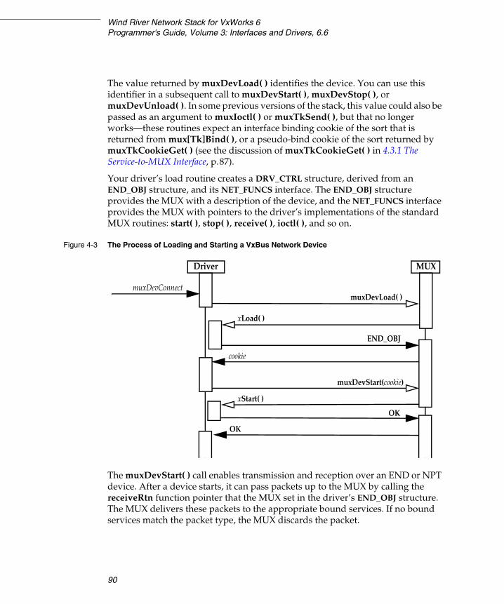
Wind River Network Stack for VxWorks 6Programmer's Guide, Volume 3: Interfaces and Drivers, 6.6
90
The value returned by muxDevLoad( ) identifies the device. You can use this identifier in a subsequent call to muxDevStart( ), muxDevStop( ), or muxDevUnload( ). In some previous versions of the stack, this value could also be passed as an argument to muxIoctl( ) or muxTkSend( ), but that no longer works—these routines expect an interface binding cookie of the sort that is returned from mux[Tk]Bind( ), or a pseudo-bind cookie of the sort returned by muxTkCookieGet( ) (see the discussion of muxTkCookieGet( ) in 4.3.1 The Service-to-MUX Interface, p.87).
Your driver’s load routine creates a DRV_CTRL structure, derived from an END_OBJ structure, and its NET_FUNCS interface. The END_OBJ structure provides the MUX with a description of the device, and the NET_FUNCS interface provides the MUX with pointers to the driver’s implementations of the standard MUX routines: start( ), stop( ), receive( ), ioctl( ), and so on.
The muxDevStart( ) call enables transmission and reception over an END or NPT device. After a device starts, it can pass packets up to the MUX by calling the receiveRtn function pointer that the MUX set in the driver’s END_OBJ structure. The MUX delivers these packets to the appropriate bound services. If no bound services match the packet type, the MUX discards the packet.
Figure 4-3 The Process of Loading and Starting a VxBus Network Device
muxDevConnect
Driver MUX
muxDevLoad( )
muxDevStart(cookie)
xLoad( )
xStart( )
END_OBJ
cookie
OK
OK
4 Integrating a New Network Interface Driver4.3 How VxWorks Launches and Uses Your Driver
91
4
When the driver passes the MUX receive routine a packet with a network service type that matches a service bound to the device, the MUX calls the service’s receive routine that the service registered when it called mux[Tk]Bind( ). If the service receive routine returns TRUE (or any non-zero value), the service consumed the packet. Otherwise, the MUX checks if any other bound service can accept the packet, and if not, discards it, freeing the associated M_BLK tuple. When a service consumes a packet, the service is responsible for freeing the packet.
To disable transmission and reception on a device, call muxDevStop( ). Call muxDevUnload( ) to remove the network interface from the MUX. Note that muxDevUnload( ) forcibly shuts down any services that are bound to the device; the service’s shutdown routine must in turn call muxUnbind( ) to unbind the service from the device.
NOTE: The Wind River Network Stack expects to borrow the buffers it receives and thus avoid data copying. If a device cannot transfer incoming data directly into clusters, the driver must explicitly copy the data from private memory into a cluster in sharable memory before passing it in an M_BLK up to the MUX. The driver must describe a packet destined for the stack as a single M_BLK/CL_BLK/cluster tuple (See Tuples, p.13).

Wind River Network Stack for VxWorks 6Programmer's Guide, Volume 3: Interfaces and Drivers, 6.6
92
4.3.3 Polled Mode – For Debugging Only
Drivers ordinarily operate in an interrupt-driven mode. During debugging, it can be convenient to have a driver operate in polled mode.
This chapter discusses routines that drivers implement to support polled-mode, and MUX routines that applications or services can call to transfer packets in polled mode.
The network stack itself does not use polled mode. Currently, only the WDB agent COMM_END back end in system mode uses polled mode. During system mode debugging, the WDB agent calls muxPollSend( ) directly in order to pass packets to the driver in polled mode.
While it is possible for an application to use a driver that has implemented the necessary APIs, and call muxPollSend( )—just as the WDB agent does—the
Figure 4-4 The Process of Stopping and Unloading a Device
for each service bound to the device
OK
OK
OKOK
OKOK
muxDevStop( )xStop( )
muxDevUnload( )
xShutdownRtn( )
muxUnbind( )
xUnload( )
MUX Driver Services
4 Integrating a New Network Interface Driver4.4 Driver Components
93
4
network stack itself does not support sending data, such as IP traffic, in polled mode. The stack will not detect that a driver is in polled mode and, consequently, will not call muxPollSend( ).
Also, the polled mode interface copies whole packets for both transmission and reception.
Thus, you cannot use polled mode routines as a high-performance polling mechanism for increasing forwarding network performance. Wind River recommends that you use polled mode only for system mode debugging over WDB.
4.4 Driver Components
A driver’s basic components include a receiver, a transmitter, and a command-and-control module.
The receiver accepts incoming frames from a DMA engine, passes these frames to the MUX, and provides the DMA engine with a continuous supply of DMA buffers. A driver receiver is stimulated by a device-generated interrupt. The driver does not directly service incoming frames in the interrupt’s context but defers this work to a routine that runs in a task context. Each instance of a driver has a private buffer pool into which incoming DMAs are directed. A driver loans individual buffers from its pool to the network stack. There is no guarantee that the stack returns the loaned buffers to the driver in order, or in any bounded time.
The transmitter accepts packets from the MUX and transfers them to the device’s transmit DMA engine, and reclaims the resources associated with each transmitted packet.
The command-and-control module configures, initializes, and provides control interfaces for the device. It is the part of the driver that parses the driver configuration parameters, quiesces the device, and configures the device in the
NOTE: The prevalent model of network interface devices available today is the direct memory access (DMA) engine. This document assumes the use of devices that are DMA engines. If you are developing a driver for a device that uses programmed I/O or some other proprietary shared memory technique, the DMA-specific portions of this text may not be directly applicable to your driver.

Wind River Network Stack for VxWorks 6Programmer's Guide, Volume 3: Interfaces and Drivers, 6.6
94
prescribed mode. It incorporates the driver’s load, unload, start, stop, and ioctl routines, as well as routines for querying and modifying the multicast filter. In essence, the driver’s command-and-control provides the driver’s external interface, with the exception of send and receive. This includes the driver interrupt service routine. Interrupts alert the driver to packets received, packet transmit DMA completion, and stall, error, or link state change conditions.
Resource Requirements
The larger the driver’s operating bandwidth, the greater its memory requirements. Occasionally, a driver does not have sufficient memory resources to accommodate the data inflow. This can be due to system constraints, buffer loaning, or CPU starvation. When a driver gets into an insufficient resource condition, it continues to provide the DMA engine with buffers into which inflowing data is transferred but the driver does not pass these buffers up to the stack.
A network service calls mux[Tk]Send( ) to request that a driver transmit a frame. This in turn calls the driver’s registered xSend( ) routine. Sends can occur at any time, and may occur before previous sends have completed transmission to the wire.
Resource reclamation of DMA buffers and control structures is generally stimulated by a device-generated transmit-complete interrupt. This interrupt announces that the device has sent a complete frame and that the driver can now return the memory resources back to the pool. In many cases, this interrupt occurs excessively. Therefore, in order to improve performance, you must reduce the frequency of transmit-complete interrupts. However, take care to ensure that you reliably return memory resources to the pool. If a device does not provide a transmit-complete interrupt, then the driver must use its own means to ensure resource reclamation.
A stall condition occurs when the device determines that it has exhausted its resources. The stall can occur in either the receiver or the transmitter. When a stall occurs, the device halts operations in the module in which it detected the stall. To resume operation, the driver must reclaim and make available sufficient resources. Often it must also clear a device register.
4 Integrating a New Network Interface Driver4.5 Transmitting Data
95
4
4.5 Transmitting Data
Unlike the receive handler, the driver’s xSend( ) routine is called from multiple contexts—network applications or tNet0 or other network tasks—which may preempt each other. The send routine also manipulates data structures and device registers which must be protected from corruption. Care must be taken to safeguard the send routine from concurrent access. Therefore, the xSend( ) routine must always take the transmit semaphore txSem referenced in the END_OBJ by calling END_TX_SEM_TAKE( ), and release it when done by calling END_TX_SEM_GIVE( ).
4.5.1 Transmit-complete Handler Interlocking Flag
Transmit-complete interrupts are typically used to allow the driver to return resources to the pool after a packet is transmitted. The frequency of these interrupts can be very high. Because of the high frequency at which these interrupts are generated, transmit-complete interrupts can potentially degrade system performance or overflow the network job pool. Handling Transmit-complete Interrupts: Freeing Resources, p.126, includes a discussion of how to reduce the frequency of this interrupt. This section deals with how to prevent the transmit-complete interrupt from exhausting the network job pool. The method used is essentially the same as that used for the receive handler interlocking flag (see Handling Receive Interrupts: Receiving Frames, p.121).
A transmit-complete handler interlocking flag is a device instance-specific flag that a driver keeps in its DRV_CTRL structure (see A.3.3 DRV_CTRL, p.290). The network driver’s ISR checks this flag before it schedules the associated service routine as a network queue job. If the ISR has not already set the flag, the ISR schedules the service routine and sets the flag. If the ISR has already set the flag, the ISR does not schedule the routine. The service routine clears the flag when it completes. In SMP environments, the ISR and the transmit complete handler routine usually need to maintain this flag as an atomic variable (see VxWorks Kernel Programmer’s Guide: Atomic Memory Operations). But even in the single processor case, you should consider the possibility of races in maintenance of the flag, particularly in cases where multiple devices may share the interrupt line and the driver’s ISR may be called even though it has disabled device interrupts.

Wind River Network Stack for VxWorks 6Programmer's Guide, Volume 3: Interfaces and Drivers, 6.6
96
4.5.2 Supporting Scatter-Gather Transmission
The MUX passes packets to the driver’s xSend( ) routine as M_BLK chains. An M_BLK chain may describe a packet consisting of more than a single block of contiguous data, in order to support scatter-gather transmission.
Scatter-gather is a DMA technique that allows for an application or network service to distribute (or “scatter”) the data it wants to send among multiple buffers rather than first collecting it into a single, contiguous buffer. The network device can then gather the data together and transfer it in a single DMA transaction, as if it were in a contiguous buffer. This capability is desirable because some network protocols distribute data across multiple moderately-sized buffers, and may also need to prefix protocol headers onto particular segments of application data. All of the network protocols in the Wind River Network Stack’s IP stack pass packets to be sent in single contiguous buffers, and also expect received packets to be delivered to them as single contiguous buffers. However, services other than those in the core Wind River IP stack may attach to an MUX-capable device, and so the network driver send routines must be able to handle M_BLK chains that describe packets with discontiguous data.
If a device does not support scatter-gather and the MUX sends the driver a fragmented packet, or if there are insufficient descriptors in the device’s transmit DMA ring to cover the multiple segments of the fragmented packet, the driver must obtain a single buffer from its pool and must then copy the packet fragments into a single buffer. This is possible because the driver pool, unlike the network stack pool, typically has only a single buffer size that is sufficient to hold the largest packet the maximum transfer unit (MTU) allows. This means that in most cases, the driver can find a buffer that is large enough to accommodate any packet. However, the overhead of requiring the driver to obtain a buffer and copy the packet fragments into the buffer is a substantial drag on overall system performance.
When a device supports scatter-gather, it can continue DMA across multiple fragments by following a list of fragment buffer pointer and size pairs. A driver written for such a device walks the M_BLK chain, extracts the cluster buffer pointers and the fragment sizes, and then forms a gather list according to the device’s specification.
Devices typically use one of two common mechanisms for creating gather lists. The first method requires the device to read the buffer pointer and size pairs out of a list contained in a single transmit descriptor. The second mechanism requires the device to follow a list of descriptors that are tied together, reading in turn the successive buffer pointer and size pairs from each descriptor in the list. (There is also a hybrid method that uses multiple pairs across multiple descriptors, but this

4 Integrating a New Network Interface Driver4.5 Transmitting Data
97
4
type is rarely used and it is usually the case that if a descriptor holds multiple pointer and size pairs, the entire packet must be held by a single descriptor’s pair list.)
The driver’s xSend( ) routine is responsible for determining if the driver has sufficient resources to handle an outgoing packet. Once this routine has made this determination, it is responsible for taking the appropriate action.
To determine whether or not there are sufficient resources available to hold the packet data, the driver’s xSend( ) routine must count the number of fragments in the M_BLK chain, and compare that number with the amount of resources the driver currently has available. Determining the amount of resources available depends on the device’s gather mechanism. As described previously, devices typically employ one of two common gather mechanisms. In each of these methods, the problem for the driver is to determine the number of fragment pairs that the currently-free descriptors can hold.
If the number of available descriptors is insufficient to hold the packet data, the driver’s xSend( ) routine may chose to do the following:
■ It may try to do some transmit clean-up work first, to free up some transmit descriptors, after which there may be sufficient descriptors to send the packet without coalescing it. (However, some driver writers prefer to do all transmit clean-up work in response to transmit-complete interrupts, not in the send routine.)
■ If there are absolutely no transmit descriptors remaining, or if the packet consists of a reasonably small number of segments and sufficient descriptors will become available shortly (after outstanding transmit-complete and transmit cleanup work is done), the xSend( ) routine may “stall” by returning END_ERR_BLOCK. The driver then must call muxTxRestart( ) in the future when more transmit resources are available.
■ If at least a single transmit descriptor remains, the driver may chose to immediately coalesce the packet into a single contiguous buffer that it allocates (usually from the same pool it uses for received packets). The driver must also do this if the packet consists of so many segments that the driver could not otherwise send it.
■ If for some reason the xSend( ) routine knows that it cannot ever send a packet, even with coalescing, it must free the packet and return ERROR. This usually indicates an error in an attached network service.
If the xSend( ) routine determines that it has sufficient resources to handle the outgoing packet, the driver must then walk the M_BLK chain. For each tuple in the chain, the driver must write the M_BLK’s data pointer and segment length into a
Wind River Network Stack for VxWorks 6Programmer's Guide, Volume 3: Interfaces and Drivers, 6.6
98
free descriptor. While it transfers the fragment pointers and lengths to the descriptor(s), it updates the descriptor fields to reflect that they hold buffer pointers that are ready for transmit. If the device specifies that the driver must distribute fragments over a list of descriptors, the device also specifies that the driver must mark the first and last descriptors in the list accordingly. After the driver transfers fragment pointers and sizes for the packet’s entire M_BLK chain to the descriptor list and sets up the descriptor fields in the manner expected by the device, the driver passes ownership of those descriptors to the device for transmission, in a device-specific manner.
4.5.3 Transmit Descriptor Clean-up
The driver’s xSend( ) routine is also responsible for storing the M_BLK pointer to the M_BLK chain holding the packet in such a way that it can be later correlated to the associated descriptor or descriptors on the transmit queue.
After the device successfully transmits a packet, most devices generate a transmit-complete interrupt. The ISR for this interrupt causes the driver’s transmit-complete handler to be scheduled, which in turn calls the driver’s transmit descriptor clean routine to free the packet descriptor or descriptors and the associated M_BLK chain. As described in Handling Transmit-complete Interrupts: Freeing Resources, p.126, numerous transmit-complete interrupts are a detriment to performance.
The driver’s xSend( ) routine may also directly call the transmit descriptor clean routine. This can be an effective method for initiating transmit descriptor clean-up. However there are two issues that you should consider:
■ When the xSend( ) routine calls the transmit descriptor clean routine, the device may not have actually transmitted the packet and there may be little or nothing to clean. Therefore, the descriptor clean-up often depends on subsequent calls to the xSend( ) routine to clean up previously-used descriptors.
■ Calling the transmit descriptor clean routine for every packet sent imposes substantial overhead.
If transmit clean-up is done only in the xSend( ) routine, significant transmit resources may be left unreturned until the MUX next calls xSend( ). One solution is to continue to allow the transmit-complete interrupt to occur but to control the frequency at which it is generated. This gives a backup to the xSend( ) routine’s clean-up attempts.

4 Integrating a New Network Interface Driver4.5 Transmitting Data
99
4
Some devices have transmit interrupt moderation settings that cause transmit interrupts to occur only after a configurable delay has passed after a transmit completes. By the time the interrupt occurs, several packets may have completed transmission and be ready for clean-up. Wind River recommends that you use such hardware facilities when they are available, since they reduce transmit interrupt load but guarantee that resources for completed transmits are (reasonably promptly) released. Modest delays in freeing particular transmitted packets rarely cause any problem; so long as packet memory pools are not exhausted, nobody is waiting for those particular packets to be freed. In contrast, hardware-imposed delays in processing received packets directly increases latency, which may be undesirable in some applications. Network drivers that might be used together with such latency-sensitive applications should be cautious about enabling hardware interrupt moderation features on the receive side.
If a device does not support transmit interrupt moderation in hardware, it may support this in software (though this is not as nice). For some devices, the transmit descriptor has a bit flag that indicates whether an interrupt should be generated when the transmit completes. This flag should, of course, only ever be set on the final descriptor describing a packet. Some drivers may choose to set it only on every nth packet, where n is small enough that it doesn’t matter much if up to n packets languish unreleased in the transmit ring until further sends occur.
One last option: To control the frequency of the transmit-complete interrupt, keep it masked, and only unmask it when a call to the transmit descriptor clean routine fails to free sufficient descriptors.
To determine if sufficient descriptors have been freed:
■ Establish a threshold of some percentage of the transmit descriptors.
■ If the xSend( ) routine’s call to the transmit descriptor clean routine does not increase the free count to greater than the threshold amount, unmask the packet-complete interrupt.

Wind River Network Stack for VxWorks 6Programmer's Guide, Volume 3: Interfaces and Drivers, 6.6
100
The solution to the transmit descriptor clean overhead is to once again track the free transmit descriptor count and to only call the transmit descriptor clean routine when the free count falls below a certain threshold.
Now put these two mitigators together:
■ Only call the transmit descriptor clean routine when the free transmit descriptor count falls below a certain threshold.
■ If the xSend( ) routine’s call to the transmit descriptor clean routine does not increase the free count to a value greater than the given threshold, unmask the transmit-complete interrupt.
4.5.4 Transmit Descriptor Indexing
The driver should allocate memory for the its transmit descriptors contiguously. This allows the driver’s xSend( ) routine to access the descriptors with an index from the base pointer returned by the allocation. This is similar to the indexing scheme used by the receive handler routine. Like the receive handler routine, the driver’s xSend( ) routine should treat the transmit descriptors as a circular array, or ring.
One of the issues that the driver’s xSend( ) routine must address is that it must track the transmit descriptors on two different queues, the free queue and the used queue. These queues are as follows:
■ free queue – lists descriptors currently available for use■ used queue – lists descriptors currently on the transmit queue
NOTE: Some driver writers prefer to do send clean-up only in the transmit clean-up routine, which the transmit-complete interrupt handler posts as a jobQueueLib job. When the ISR posts such a job, it also disables further transmit interrupts from the device; transmit interrupts stay disabled until the transmit-cleanup job completes and reenables them. Under heavy load this suffices to moderate the number of transmit interrupts. This method is simple and always assures prompt clean-up of transmit resources. However, under conditions of moderate load insufficient to keep a transmit clean-up job delayed long enough to accomplish batching, it may have more overhead than doing clean-up in the xSend( ) routine. A further concern is that in SMP environments, the transmit clean-up job may run on a different CPU than the sending thread(s), and so may contend with the sending thread(s) for the driver’s transmit semaphore.

4 Integrating a New Network Interface Driver4.5 Transmitting Data
101
4
These queues are actually different dynamic parts of the same ring of descriptors. Setting up and efficiently managing these queues is a critical part of the xSend( ) routine. To manage these queues the driver establishes two indices, one for each queue.
The index for the free queue—the free index—references the next descriptor available for use by xSend( ). The xSend( ) routine should follow the free index around the transmit descriptor ring. When xSend( ) places a descriptor on the device’s transmit queue, it increments the free index. In order to track how many descriptors are currently free, xSend( ) also decrements a free counter. The initial state for the free counter is the total number of transmit-descriptors that the driver allocated.
The index for the used queue references the descriptor that has been on the device’s transmit queue for the longest period of time. The used queue is also the next-to-clean queue. The index for the next-to-clean queue is the clean index, this references the next transmit descriptor that the transmit descriptor clean routine is to clean (see 4.5.7 Transmit Descriptor Clean, p.102).
4.5.5 Transmit Packet Association List
It is the responsibility of the driver’s xSend( ) routine to store a transmitted packet’s M_BLK chain pointer in such a way that the driver transmit cleanup handler can later correlate it with the associated descriptor or descriptors on the transmit queue. The mechanism to do this is a transmit packet association list.
This list is an array of M_BLK pointers that is of equal length to the total number of transmit descriptors allocated by the driver. This list is accessed using the same indices that the driver uses to reference the descriptors. When xSend( ) places a descriptor on the device transmit queue, it uses the free index to correlate the transmit packet association list to the transmit descriptor ring. As xSend( ) moves around the transmit descriptor ring, for each fragment buffer pointer it puts into a descriptor, it determines if that fragment is the last fragment for the packet it is transmitting. If it is the last fragment for the packet, xSend( ) puts the pointer to the packet’s M_BLK chain into the transmit packet association list at the same index as the descriptor that holds the packet’s last fragment. If the fragment is not the last fragment of packet, xSend( ) sets the corresponding transmit packet association list entry to NULL. This prevents freeing the packet until all segments of the packet have been transmitted.

Wind River Network Stack for VxWorks 6Programmer's Guide, Volume 3: Interfaces and Drivers, 6.6
102
4.5.6 Transmit-complete Handler
The transmit-complete handler is a task-level routine that is scheduled by the transmit-complete interrupt’s ISR. See Handling Transmit-complete Interrupts: Freeing Resources, p.126.
4.5.7 Transmit Descriptor Clean
The transmit descriptor clean routine returns transmit descriptors back to a usable state and frees the associated M_BLK chains. This routine uses the clean index to rotate through the driver’s transmit descriptors (see 4.5.4 Transmit Descriptor Indexing, p.100). As this routine moves around the ring, it determines if the device has completed transmission of the descriptor currently referenced by the clean index, and released it from the device transmit queue. If so, this routine does whatever is necessary to put the descriptor back into a free state, and increments the free counter. This routine continues to traverse the ring until it encounters a descriptor that the device has not released from the device transmit queue or until the free counter equals the number of transmit descriptors created by the device.
When this routine determines that the device has released a descriptor from the device transmit queue, it uses the clean index to reference the transmit packet association list. If this routine finds that this list entry holds an M_BLK pointer, it frees the M_BLK chain by calling netMblkClChainFree( ).
4.6 Implementing Checksum Offloading
TCP/IP checksum offloading eliminates host-side checksum calculation overhead by performing checksum computation with hardware assist. Many devices support this feature.
The device and driver must act in concert to implement checksum offloading. The device supports checksum offloading in the DMA engine. The DMA engine computes the raw, 16-bit, ones-complement checksum of each DMA transfer as it moves the data to and from host memory. To use this checksum instead of the software-generated checksum requires that you set CSUM flags in the packet’s M_BLK to either bypass the software checksum computation for received packets,

4 Integrating a New Network Interface Driver4.6 Implementing Checksum Offloading
103
4
or to alert the device that it needs to compute and insert checksums before it transmits a frame.
The Wind River Network Stack checksum offloading API supports offload of the TCP or UDP transport layer checksum and the IPv4 header checksum on both transmission and reception. The API consists of the END_CAPABILITIES class defined in end.h (see A.3.4 END_CAPABILITIES, p.290), the csum_flags and csum_data fields in the mBlkPktHdr structure in the lead M_BLK of a packet, and the EIOCGIFCAP and EIOCSIFCAP ioctls in the driver.
The argument to both the EIOCGIFCAP and EIOCSIFCAP MUX ioctl commands is a pointer to an END_CAPABILITIES structure that can describe the supported and currently enabled hardware offload capabilities of the device. The stack uses the EIOCGIFCAP ioctl to read the device’s capabilities. The stack need not initialize any members of the input END_CAPABILITIES structure. The driver’s handler for EIOCGIFCAP returns all fields of the structure according to its current settings, as shown in Example 4-1.
Example 4-1 EIOCGIFCAP Example:
int xIoctl(END_OBJ * pEnd,int cmd,caddr_t data){MY_DRV_CTRL * pDrvCtrl;int error = OK;END_CAPABILITIES * hwCaps;
pDrvCtrl = (MY_DRV_CTRL *)pEnd;
switch (cmd){... case EIOCGIFCAP:
hwCaps = (END_CAPABILITIES *) data;
if (hwCaps == NULL){error = EINVAL;break;}
hwCaps->csum_flags_tx = pDrvCtrl->hwCaps.csum_flags_tx;hwCaps->csum_flags_rx = pDrvCtrl->hwCaps.csum_flags_rx;hwCaps->cap_available = pDrvCtrl->hwCaps.cap_available;hwCaps->cap_enabled = pDrvCtrl->hwCaps.cap_enabled;break;
... }
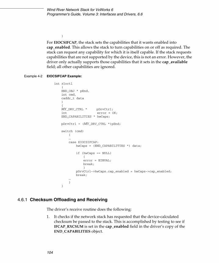
Wind River Network Stack for VxWorks 6Programmer's Guide, Volume 3: Interfaces and Drivers, 6.6
104
}
For EIOCSIFCAP, the stack sets the capabilities that it wants enabled into cap_enabled. This allows the stack to turn capabilities on or off as required. The stack can request any capability for which it is itself capable. If the stack requests capabilities that are not supported by the device, this is not an error. However, the driver only actually supports those capabilities that it sets in the cap_available field; all other capabilities are ignored.
Example 4-2 EIOCSIFCAP Example:
int xIoctl(END_OBJ * pEnd,int cmd,caddr_t data){MY_DRV_CTRL * pDrvCtrl;int error = OK;END_CAPABILITIES * hwCaps;
pDrvCtrl = (MY_DRV_CTRL *)pEnd;
switch (cmd){... case EIOCSIFCAP:
hwCaps = (END_CAPABILITIES *) data;
if (hwCaps == NULL){error = EINVAL;break;}
pDrvCtrl->hwCaps.cap_enabled = hwCaps->cap_enabled;break;
... }
}
4.6.1 Checksum Offloading and Receiving
The driver’s receive routine does the following:
1. It checks if the network stack has requested that the device-calculated checksum be passed to the stack. This is accomplished by testing to see if IFCAP_RXCSUM is set in the cap_enabled field in the driver’s copy of the END_CAPABILITIES object.
4 Integrating a New Network Interface Driver4.6 Implementing Checksum Offloading
105
4
2. If the stack enabled receive checksumming, the driver reads the device’s checksum status, usually a field in the receive DMA descriptor for the packet.
a. The driver determines if the device checked the IP checksum
If the device checked the IP header checksum, the driver sets CSUM_IP_CHECKED in the packet’s pMblk->mBlkPktHdr.csum_flags to indicate that the IP header checksum was checked.
b. The driver tests to see if the device determined that the IP header is valid.
If the IP header is valid, the driver sets CSUM_IP_VALID in the packet’s pMblk->mBlkPktHdr.csum_flags to indicate that the IP header is valid. This bit is only meaningful when the driver has also set CSUM_IP_CHECKED.
c. The driver tests if the device calculated the TCP or UDP checksum.
i. If the device calculated the TCP or UDP checksum, the driver sets CSUM_DATA_VALID in the packet’s pMblk->mBlkPktHdr.csum_flags, and stores the calculated checksum value (the uncomplemented, 16-bit, ones-complement sum over the transport header, transport layer data, and possibly the IP pseudo-header) in pMblk->mBlkPktHdr.csum_data. The driver writes this sum in host byte order into the low-order 16 bits of csum_data to indicate that the device calculated the TCP or UDP checksum and that the packet is valid.
ii. If the transport checksum calculated by the device includes the IP pseudo-header sum, the driver also sets CSUM_PSEUDO_HDR in the packet’s pMblk->mBlkPktHdr.csum_flags. Otherwise, the stack expects that the value in pMblk->mBlkPktHdr.csum_data covers only the transport header and transport data, and it will adjust for the pseudo-header checksum itself.
iii. If the device directly indicates whether the transport layer checksum is valid, the driver may set both CSUM_DATA_VALID and CSUM_PSEUDO_HDR in pMblk->mBlkPktHdr.csum_flags, and write 0xffff to pMblk->mBlkPktHdr.csum_data if the checksum was valid, or write any other value (0 is suggested) to that field if the checksum was found invalid. It is permissible to only set csum_flags and csum_data in case the device finds the checksum valid. This is a workaround for devices that in certain circumstances misidentify a correct checksum as invalid, but are trusted if they indicate a checksum is valid. The stack verifies the transport checksum in software if CSUM_DATA_VALID is not set.

Wind River Network Stack for VxWorks 6Programmer's Guide, Volume 3: Interfaces and Drivers, 6.6
106
Example 4-3 Handling Packets with Bad or Unchecked Transport Checksums
This example receive checksum offload code handles packets that the device indicates have bad transport checksums, or for which the device did not check the transport checksum, by letting the stack verify the transport checksum in software:
/* Do RX checksum offload, if enabled. */
if (pDrvCtrl->hwCaps.cap_enabled & IFCAP_RXCSUM){/* Read the device checksum status field */RFD_BYTE_RD (pRbdTag->pRFD, RFD_CSUMSTS_OFFSET, csumStatus);
/* Determine if IP checksum calculated */
if (csumStatus & RFD_CS_IP_CHECKSUM_BIT_VALID){/* Set M_BLK check sum flags to indicate checksum calculated */pRbdTag->pMblk->m_pkthdr.csum_flags |= CSUM_IP_CHECKED;}
/* Determine if IP checksum valid
if (csumStatus & RFD_CS_IP_CHECKSUM_VALID){/* Set M_BLK check sum flags to indicate a valid IP header */pRbdTag->pMblk->m_pkthdr.csum_flags |= CSUM_IP_VALID;}
if (csumStatus & RFD_CS_TCPUDP_CHECKSUM_BIT_VALID &&csumStatus & RFD_CS_TCPUDP_CHECKSUM_VALID){pRbdTag->pMblk->m_pkthdr.csum_flags |=
CSUM_DATA_VALID|CSUM_PSEUDO_HDR;pRbdTag->pMblk->m_pkthdr.csum_data = 0xFFFF;}
}
4.6.2 Checksum Offloading and Transmission
The network stack tells the driver whether or not to instruct the device to calculate checksums for a given packet being transmitted, through CSUM flags in pMblk->m_pkthdr.csum_flags. The stack sets the CSUM_IP bit if it wants the device to calculate the IPv4 header checksum, and sets CSUM_TCP or CSUM_UDP or CSUM_TCPv6 or CSUM_UDPv6 to ask the device to calculate the TCP or UDP checksum in an IPv4 or IPv6 datagram. The stack also provides some additional information that may be needed by some devices:
■ The stack stores in the lead M_BLK of the packet the IP header length (including any IP options). You may access this field by using the CSUM_IP_HDRLEN( ) macro (see Table 4-1). Note that if the device has

4 Integrating a New Network Interface Driver4.6 Implementing Checksum Offloading
107
4
limitations that prevent it from calculating and inserting checksums correctly on certain legal packets, such as IP packets with options, the driver must either calculate the checksums on those exceptional packets in software, or must not claim to support transmit checksum offload for the affected protocol at all.
■ The stack stores in the lead M_BLK the byte offset of the transport-level checksum field within the transport header, relative to the start of the transport header. You can access this field by using the CSUM_XPORT_CSUM_OFF( ) macro (see Table 4-1). You may also infer this value from the particular transport-level CSUM flag used: it is 6 for UDP and 16 for TCP.
When requesting TCP or UDP checksum offload, the stack always calculates the uncomplemented pseudo-header checksum and stores it in network byte order in the transport header checksum field. The device can overwrite it but the stack always calculates it. This cannot be turned off.
The stack stores the checksums in the headers at the front of each IP packet, and the device must complete the checksum before it can transmit the packet headers. Because the device’s DMA engine computes the checksums, the last byte of the packet must arrive in the device before it can determine the complete checksum. That is, in order for the device to calculate a checksum on a packet, it must delay transmission of any part of the packet until after it processes the entire packet.
The driver’s xSend( ) routine must do the following:
1. Determine whether or not the network stack needs the device to calculate checksums for the packet it is processing. To do this, the routine reads pMblk->m_pkthdr.csum_flags.
a. If the network stack requests that the device calculate the IP checksum, the driver prepares to set the device accordingly.
b. If the network stack requests that the device calculate the TCP or UDP checksum, the driver prepares to set the device accordingly.
Table 4-1 Checksum Support Macros
Flag Description
CSUM_IP_HDRLEN(M_BLK) The actual IP header length of M_BLK
CSUM_XPORT_CSUM_OFF(M_BLK) The offset within the transport header of the transport checksum field in M_BLK
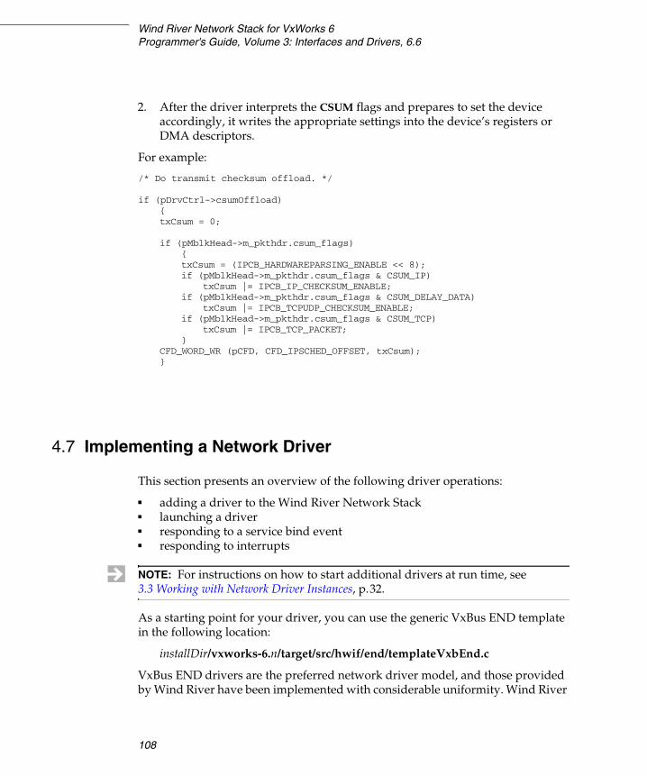
Wind River Network Stack for VxWorks 6Programmer's Guide, Volume 3: Interfaces and Drivers, 6.6
108
2. After the driver interprets the CSUM flags and prepares to set the device accordingly, it writes the appropriate settings into the device’s registers or DMA descriptors.
For example:
/* Do transmit checksum offload. */
if (pDrvCtrl->csumOffload){txCsum = 0;
if (pMblkHead->m_pkthdr.csum_flags){txCsum = (IPCB_HARDWAREPARSING_ENABLE << 8);if (pMblkHead->m_pkthdr.csum_flags & CSUM_IP)
txCsum |= IPCB_IP_CHECKSUM_ENABLE;if (pMblkHead->m_pkthdr.csum_flags & CSUM_DELAY_DATA)
txCsum |= IPCB_TCPUDP_CHECKSUM_ENABLE;if (pMblkHead->m_pkthdr.csum_flags & CSUM_TCP)
txCsum |= IPCB_TCP_PACKET;}
CFD_WORD_WR (pCFD, CFD_IPSCHED_OFFSET, txCsum);}
4.7 Implementing a Network Driver
This section presents an overview of the following driver operations:
■ adding a driver to the Wind River Network Stack■ launching a driver■ responding to a service bind event■ responding to interrupts
As a starting point for your driver, you can use the generic VxBus END template in the following location:
installDir/vxworks-6.n/target/src/hwif/end/templateVxbEnd.c
VxBus END drivers are the preferred network driver model, and those provided by Wind River have been implemented with considerable uniformity. Wind River
NOTE: For instructions on how to start additional drivers at run time, see 3.3 Working with Network Driver Instances, p.32.
4 Integrating a New Network Interface Driver4.7 Implementing a Network Driver
109
4
still ships various drivers of the old non-VxBus END model, and you can find a template for these legacy drivers at the following location:
installDir/vxWorks-6.n/target/src/drv/end/templateEnd.c
Apart from the issues of how VxBus END drivers fit into the VxBus subsystem, and the fact that the legacy drivers are more various in their implementations, the recommendations for how both VxBus and legacy END drivers are constructed are essentially the same.
For the most part, NPT drivers and ENDs handle these operations identically. The major exceptions are in receiving and sending frames. Both NPT drivers and ENDs pass received frames whole (with link header present) to the MUX, however NPT drivers pass up additional information that makes it easy to strip the link header. On the send side, the MUX always passes to an END’s xSend( ) routine a whole frame with the link header present, but may pass a packet without a link header to an NPT driver’s xSend( ) routine. In that case, the NPT xSend( ) routine has to form the link header itself based upon the destination address and network service type that the MUX also passes it. These differences are highlighted in the sections that follow. See 4.1.1 How ENDs and NPT Drivers Differ, p.82 for an overview of these differences.
Currently, the Wind River Network Stack does not include any NPT driver implementations, only END implementations.
4.7.1 Adding a Network Driver
You add your network driver to the Wind River Network Stack in much the same way as you add any other application to a target image. The first step is to compile and include the driver code in the image.
About VxBus Network Drivers
Like other VxBus drivers, a VxBus network driver must provide a driver registration routine as an external API. For example, the vxbEtsecEnd.c driver provides etsecRegister( ), and the gei825xxVxbEnd.c driver provides
NOTE: The design situations that require an NPT driver instead of an END are rare. If you are writing a new driver, think first of implementing it as an END, for which there exists templates as well as working driver implementations that you can study. If porting a packet-oriented driver, feel free to port it as an NPT driver. The Wind River Network Stack allows you to use drivers of both styles (controlling different devices) in the same image.
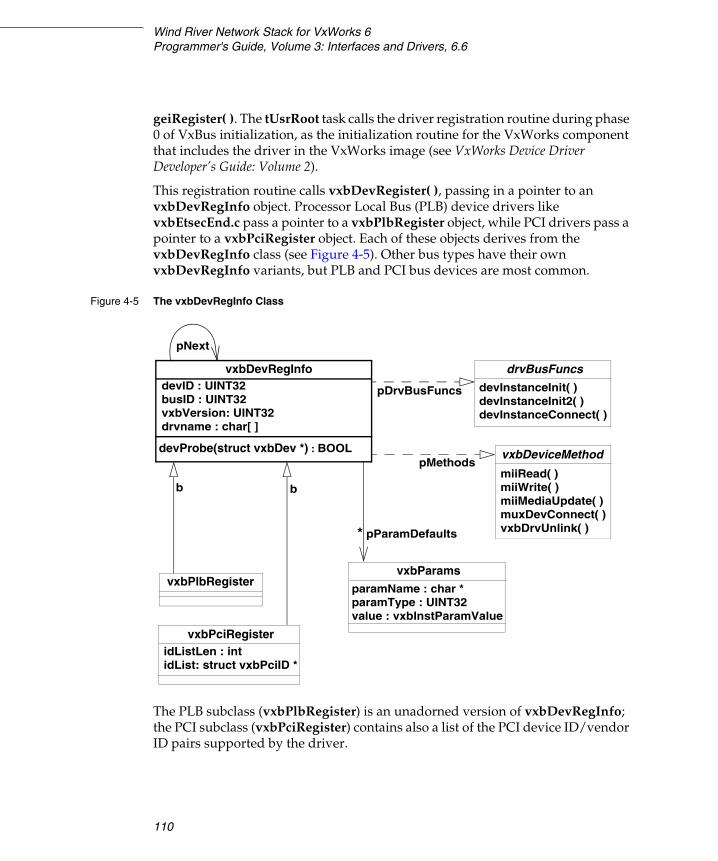
Wind River Network Stack for VxWorks 6Programmer's Guide, Volume 3: Interfaces and Drivers, 6.6
110
geiRegister( ). The tUsrRoot task calls the driver registration routine during phase 0 of VxBus initialization, as the initialization routine for the VxWorks component that includes the driver in the VxWorks image (see VxWorks Device Driver Developer’s Guide: Volume 2).
This registration routine calls vxbDevRegister( ), passing in a pointer to an vxbDevRegInfo object. Processor Local Bus (PLB) device drivers like vxbEtsecEnd.c pass a pointer to a vxbPlbRegister object, while PCI drivers pass a pointer to a vxbPciRegister object. Each of these objects derives from the vxbDevRegInfo class (see Figure 4-5). Other bus types have their own vxbDevRegInfo variants, but PLB and PCI bus devices are most common.
The PLB subclass (vxbPlbRegister) is an unadorned version of vxbDevRegInfo; the PCI subclass (vxbPciRegister) contains also a list of the PCI device ID/vendor ID pairs supported by the driver.
Figure 4-5 The vxbDevRegInfo Class
vxbDevRegInfodevID : UINT32
devProbe(struct vxbDev *) : BOOL
pNext
drvBusFuncs
b
vxbPlbRegister
vxbPciRegister
b
vxbParams
idListLen : intidList: struct vxbPciID *
busID : UINT32vxbVersion: UINT32drvname : char[ ]
pDrvBusFuncs
vxbDeviceMethodpMethods
* pParamDefaults
devInstanceInit( )devInstanceInit2( )devInstanceConnect( )
miiRead( )miiWrite( )miiMediaUpdate( )muxDevConnect( )vxbDrvUnlink( )
paramName : char *paramType : UINT32value : vxbInstParamValue
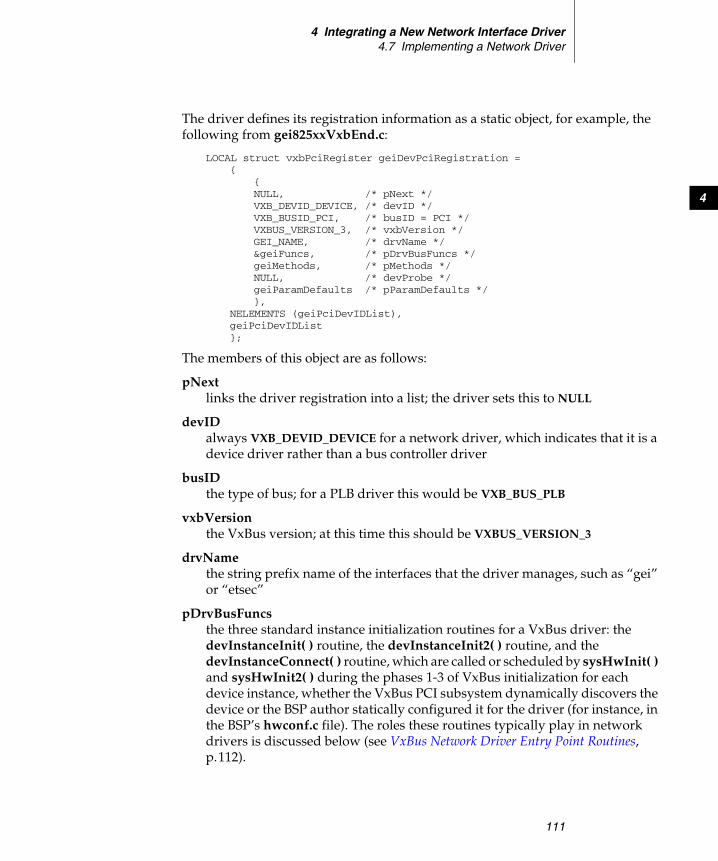
4 Integrating a New Network Interface Driver4.7 Implementing a Network Driver
111
4
The driver defines its registration information as a static object, for example, the following from gei825xxVxbEnd.c:
LOCAL struct vxbPciRegister geiDevPciRegistration ={
{NULL, /* pNext */VXB_DEVID_DEVICE, /* devID */VXB_BUSID_PCI, /* busID = PCI */VXBUS_VERSION_3, /* vxbVersion */GEI_NAME, /* drvName */&geiFuncs, /* pDrvBusFuncs */geiMethods, /* pMethods */NULL, /* devProbe */geiParamDefaults /* pParamDefaults */},
NELEMENTS (geiPciDevIDList),geiPciDevIDList};
The members of this object are as follows:
pNext links the driver registration into a list; the driver sets this to NULL
devID always VXB_DEVID_DEVICE for a network driver, which indicates that it is a device driver rather than a bus controller driver
busID the type of bus; for a PLB driver this would be VXB_BUS_PLB
vxbVersion the VxBus version; at this time this should be VXBUS_VERSION_3
drvName the string prefix name of the interfaces that the driver manages, such as “gei” or “etsec”
pDrvBusFuncs the three standard instance initialization routines for a VxBus driver: the devInstanceInit( ) routine, the devInstanceInit2( ) routine, and the devInstanceConnect( ) routine, which are called or scheduled by sysHwInit( ) and sysHwInit2( ) during the phases 1-3 of VxBus initialization for each device instance, whether the VxBus PCI subsystem dynamically discovers the device or the BSP author statically configured it for the driver (for instance, in the BSP’s hwconf.c file). The roles these routines typically play in network drivers is discussed below (see VxBus Network Driver Entry Point Routines, p.112).

Wind River Network Stack for VxWorks 6Programmer's Guide, Volume 3: Interfaces and Drivers, 6.6
112
pMethods a table of VxBus “methods” that the driver implements. Methods are in principle optional, but most drivers implement miiRead( ), miiWrite( ), miiMediaUpdate( ), muxDevConnect( ), and vxbDrvUnlink( ) methods. The roles of these methods are described in VxBus Network Driver Methods, p.114.
devProbe if the driver provides this routine, the VxBus system calls it during device discovery (from vxbNewDriver( ) and vxbDeviceAnnounce( )) to check whether the driver should control this candidate device. The VxBus system passes this routine a pointer to the candidate instance (struct vxbDev), and returns TRUE if the driver should control the device, and FALSE if the driver should not control the device. The probe routine may attempt to access device registers if necessary. The VxBus system calls this routine early in start-up before the system memory pool is initialized and before the task spawned by sysHwInit2( ) calls the driver’s devInstanceConnect( ) routine. Most drivers will not need a probe routine; in particular, even without a probe routine, PCI drivers would not be associated with PCI devices that do not match the device ID / vendor ID pairs listed in the vxbPciRegister object’s idList, while BSP authors usually configure PLB devices statically through the BSP’s hwconf.c file.
pParamDefaults a table of VXB_PARAMETERS that the driver initializes to their default values. The VxBus parameter system allows you to override the defaults on a per-instance basis. These parameters can be any configurable information that the driver requires for its instances, but commonly specify items such as what network job queue the driver is to post work to, whether the driver should enable jumbo frames, whether the driver should enable interrupt coalescing, and so on.
VxBus Network Driver Entry Point Routines
The pDrvBusFuncs interface of the driver registration information object has three routines that the driver implements. The routines sysHwInit( ) and sysHwInit2( ) (or tasks spawned by these routines) call the routines in this interface in sequence during system boot for each device instance that the driver will manage. Each routine takes a pointer to a vxbDev structure (a VXB_DEVICE_ID) and returns void:
■ devInstanceInit( )
sysHwInit( ) usually calls this routine, indirectly, during phase 1 of VxBus initialization, before the system memory pool has been initialized.
4 Integrating a New Network Interface Driver4.7 Implementing a Network Driver
113
4
For a network driver, this routine typically only sets the device unit number. Network drivers managing devices that are statically configured (typically PLB devices) call vxbInstUnitSet( ) to set the unit number that the BSP author configured for the device in hwconf.c. Drivers managing devices that the VxBus system dynamically discovers, typically PCI drivers, call vxbNextUnitGet( ) to allocate and assign the next available free unit number to the device.
■ devInstanceInit2( )
sysHwInit( ) usually calls this routine, indirectly, during phase 2 of VxBus initialization, after the system memory pool has been initialized.
The driver’s devInstanceInit2( ) routine does the following tasks:
– allocates and initializes the driver-specific control structure for the instance and associates it with the instance’s vxbDev structure
– allocates memory for the instance’s transmit and receive DMA rings, but not for the driver’s receive packet pool
– resets the device, ensuring that it is in a quiescent state– determines the device’s MAC address, and stores a copy in the driver
control structure– optionally reads various VxBus instance parameters to help configure the
device– creates and initializes (in most devices) an MII bus, and sets the initial MII
bus mode
Also, generic PCI drivers that may run on different boards or architectures create and initialize vxbDmaBufLib tags and maps, which support driver DMA, dealing with complexities such as address translation, access windows, bounce buffers, cache coherence, scatter-gather, buffer alignment restrictions, and the like in a transparent and consistent way. (Drivers that will operate only on a single board or architecture environment may choose to omit the use of vxbDmaBufLib to avoid the small overhead that it imposes.)
■ devInstanceConnect()
This routine is called during phase 3 of VxBus initialization, usually from a task spawned late in sysHwInit2( ). This call-out in the VxBus model allows the driver to connect the instance to a “higher level entity.” One might expect that this is where the network driver connects the device instance to the MUX, but that is not the case: at the time the task calls this routine, the MUX may still not have been initialized yet. In most network drivers, this routine does nothing.

Wind River Network Stack for VxWorks 6Programmer's Guide, Volume 3: Interfaces and Drivers, 6.6
114
VxBus Network Driver Methods
VxBus provides a way for a driver to advertise that it provides a routine that implements an optional, well-known “method.” Methods are typically used for common functionality that might be implemented in a diverse class of drivers, but that for one reason or another a particular driver might choose not to implement.
VxBus network drivers typically implement the following methods:
■ muxDevConnect( )
This method does the following:
■ calls muxDevLoad( ) to load the network device into the MUX
■ calls muxDevStart( ) to start the network device
■ vxbDrvUnlink( )
This method shuts down a device instance in response to an unlink event from VxBus. This may occur if you have terminated the VxBus instance or unloaded the driver. When an unlink event occurs, the driver must shut down and unload the network interface associated with this device instance from the MUX, and then release all the resources that the driver allocated in its devInstanceInit2( ) and xLoad( ) routines during instance creation, such as vxbDma memory and maps, and interrupt handles. It also must destroy its child miiBus and PHY devices.
Adding VxBus Drivers and Devices
To add a VxBus network driver, describe the driver as a component in a .cdf file, list its driver registration function as its INIT_RTN, specify the appropriate initialization order, and list any required dependencies that cannot be determined by the linker. For example:
/* 40vxbEtsecEnd.cdf - Component configuration file */Component INCLUDE_ETSEC_VXB_END
{NAME Enhanced TSEC VxBus Enhanced Network DriverSYNOPSIS Enhanced TSEC VxBus Enhanced Network DriverHDR_FILES ../src/hwif/h/end/vxbEtsecEnd.hCHILDREN FOLDER_DRIVERSINIT_ORDER hardWareInterFaceBusInitINIT_RTN etsecRegister();REQUIRES INCLUDE_PLB_BUS \INCLUDE_PARAM_SYS \INCLUDE_BCM54XXPHY \INCLUDE_MV88E1X11PHY \INCLUDE_DMA_SYSINIT_AFTER INCLUDE_PLB_BUS}
4 Integrating a New Network Interface Driver4.7 Implementing a Network Driver
115
4
For the traditional BSP command line build (that is, as opposed to the vxprj command line build), you must create forward declaration (.dc) and driver registration (.dc) stub files in installDir/target/config/comps/src/hwif/ that the build system uses to generate the file vxbUsrCmdLine.c that it uses to initialize the VxBus. See the README file in the above directory for more information.
In addition, for PLB bus drivers, the device units must be statically configured in each supporting BSPs hwconf.c file, listed in the hcfDeviceList[ ] array.
For legacy ENDs and NPT drivers, those that are not VxBus drivers, the mechanism to include the driver in the VxWorks image and get it connected to the MUX is somewhat different, as follows:
Adding Legacy Network Drivers and Devices
This section applies to BSPs that do not support VxBus, and to ENDs and NPT drivers that do not conform to the VxBus driver model.
The BSP defines a table that lists entries for network device units controlled by various drivers that the BSP supports. This table, endDevTbl[ ],is defined in the configNet.h file in this directory:
installDir/vxworks-6.n/target/config/bspName
(bspName is the name of your board support package, such as mv162 or pc486.)
For example, to add an ln7990 END, you would edit configNet.h to contain lines such as:
/* Parameters for loading ln7990 END supporting buffer loaning. */#define LN7990_LOAD_FUNC_0 ln7990EndLoad#define LN7990_LOAD_STRING_0 "0xfffffe0:0xffffffe2:0:1:1"#define LN7990_LOAD_BSP_0 NULL
Define three constants, like those shown above, for each of the devices you want to add. To set appropriate values for these constants, consider the following:
MY_LOAD_FUNCThe name of your driver’s xLoad( ) entry point (see Driver Implementations of the xLoad( ) Routine, p.128). For example, if your driver’s xLoad( ) entry point is ln7990EndLoad( ), edit configNet.h to include the line:
#define LN7990_LOAD_FUNC ln7990EndLoad
MY_LOAD_STRING_UNIT The initialization string passed into muxDevLoad( ) as the pInitString parameter. This string contains information that muxDevLoad( ) prefixes with “unitNumber:” and passes to your driver’s xLoad( ) routine. Its contents depend on what the driver expects.
Wind River Network Stack for VxWorks 6Programmer's Guide, Volume 3: Interfaces and Drivers, 6.6
116
Some BSPs define MY_LOAD_FUNC as a wrapper routine which is responsible for calling the real driver load routine with appropriate arguments. In this case, MY_LOAD_STRING_UNIT is often NULL.
MY_LOAD_BSP_UNIT BSP-specific additional information to be passed as the last argument to muxDevLoad( ) for use by the driver. This is most frequently NULL, and if so, there is no need to actually define the MY_LOAD_BSP_UNIT macros.
You must also edit the definition of the endDevTbl[ ] to include entries for each of the devices to be loaded:
END_TBL_ENTRY endDevTbl [] ={{ 0, MY_LOAD_FUNC, MY_LOAD_STRING_0, MY_LOAD_BSP_0, NULL, FALSE },{ 1, MY_LOAD_FUNC, MY_LOAD_STRING_1, MY_LOAD_BSP_1, NULL, FALSE },... { 0, END_TBL_END, NULL, 0, NULL, FALSE },};
The first number in each table entry specifies the unit number for the device. The first entry in the example above specifies a unit number of 0. Thus, the device it loads is deviceName0. The FALSE at the end of each entry indicates that the entry has not been processed. After the system successfully loads a driver, it changes this value to TRUE in the run-time version of this table. To prevent the system from automatically loading your driver, set this value to TRUE in the table.
Some BSPs, typically those supporting PCI END devices, construct entries in the endDevTbl[ ] array at run time. Such BSPs pre-populate the table with several empty entries. The BSP must provide code that scans the PCI bus for the devices that are managed by PCI END drivers that the BSP supports (and that are to be included in the image). For each such located device, the BSP consumes an entry in endDevTbl[ ] corresponding to the located device, identifying it as a unit device for a particular driver. The BSP must save any PCI configuration space information that the driver may need for these devices, including such things as register addresses (BARs), device IDs, interrupt lines, and possibly revision numbers. Typically this information is stored in auxiliary arrays that are used by a wrapper driver load routine to construct the driver load string for the real END driver load routine, which the wrapper calls. Different BSPs accomplish all this in various different ways; this non-uniformity and code duplication is one of the things the VxBus system is intended to eliminate.
After you add these entries to the table, rebuild the VxWorks image to include your new drivers. When you boot this rebuilt image, the system calls muxDevLoad( ) for each device specified in the table in the order listed.
4 Integrating a New Network Interface Driver4.7 Implementing a Network Driver
117
4
In addition, VxWorks drivers are often written to be independent of the bus and processor configuration. This means that the methods used to access device registers are provided by the BSP and not by the driver. For each such driver, each BSP that supports it must provide the required register access routines. Legacy network drivers often require other support routines from the BSPs that support them, such as routines for enabling or disabling interrupts for the device at a board/interrupt controller level, busy-waiting for short amounts of time, and so on. The driver documentation lists the routines that the BSP must provide.
4.7.2 Launching the Driver
At system startup, VxWorks spawns the user root task to initialize the system. This task eventually calls muxDevLoad( ), which calls the xLoad( ) routine in your driver. The xLoad( ) routine creates and partially populates its own DRV_CTRL structure (which is its own custom derivation of the END_OBJ class, see A.3.8 END_OBJ, p.297) and a NET_FUNCS structure. These structures describe the driver to the MUX. The NET_FUNCS structure provides the MUX with references to the MUX-callable driver routines. It is typically static and is shared between all network devices that the driver manages.
After muxDevLoad( ) loads your driver, a muxDevStart( ) call executes your driver’s implementation of the start( ) routine referenced in the NET_FUNCS interface. This xStart( ) routine activates the driver and registers an interrupt service routine for the driver with the appropriate interrupt connect routine for your architecture and BSP.
4.7.3 Responding to Network Service Bind Calls
A driver typically does not react when a service binds to a device. But if you want your driver to respond to a bind event, your driver can implement an xEndBind( ) routine. To get a pointer to a driver’s xEndBind( ) implementation, the MUX does not look in the NET_FUNCS interface, as it does for other calls, but instead issues an EIOCQUERY command to the driver’s xIoctl( ) routine. As input, the call supplies an END_QUERY structure (see A.3.10 END_QUERY, p.301) whose members are used as follows:
query The MUX sets this to END_BIND_QUERY.
NOTE: The endDevTbl[ ] table can contain a mix of NPT drivers and ENDs.

Wind River Network Stack for VxWorks 6Programmer's Guide, Volume 3: Interfaces and Drivers, 6.6
118
queryLen The MUX sets this to the expected size of the function pointer in queryData.
queryData Your driver’s implementation of the ioctl( ) routine overwrites this field with a pointer to your driver’s xEndBind( ) routine. The MUX then calls this routine with the following arguments:
xEndBind (pEnd, pNetSvcInfo, pNetDrvInfo, type);
where pEnd is a pointer to the END_OBJ, pNetSvcInfo and pNetDrvInfo are the last two arguments passed to muxTkBind( ), or are NULL in a muxBind( ) call, and type is the protocol type of the service being bound, either an ethertype value or MUX_PROTO_SNARF or MUX_PROTO_PROMISC or MUX_PROTO_OUTPUT. If the queryData( ) call returns ERROR, the bind fails. Note that there is no established convention for use of the pNetSvcInfo and pNetDrvInfo pointers; they are only useful if the driver and the service are jointly written to have knowledge of each other and how these parameters should be interpreted. Due to this level-breaking, a bind function is rarely implemented.
4.7.4 Responding to Interrupts
A driver’s interrupt handler typically handles three varieties of interrupt:
■ a receive interrupt that indicates a packet has been received on the device
■ a transmit-complete interrupt that indicates that a packet has been sent over the device and its resources can be released
■ an error condition interrupt
When a device interrupt occurs, the Wind River Network Stack invokes the interrupt service routine (ISR) that your driver registered during its xStart( ) routine. Your ISR in turn schedules task-level handlers to respond to the particular varieties of interrupts that it receives.
Example 4-4 The ISR from the gei825xxVxbEnd.c Driver
For some devices, a single ISR may be used to handle all device interrupts. Here is the driver ISR from the gei825xxVxbEnd.c driver:
LOCAL void geiEndInt(GEI_DRV_CTRL * pDrvCtrl){

4 Integrating a New Network Interface Driver4.7 Implementing a Network Driver
119
4
VXB_DEVICE_ID pDev;UINT32 status;
pDev = pDrvCtrl->geiDev;
/* Read interrupt cause register. Note that this acknowledges* any pending interrupts.*/
status = CSR_READ_4(pDev, GEI_ICR);
/** Make sure there's really an interrupt event pending for us.* Since we're a PCI device, we may be sharing an interrupt line* with another device. If we are, our ISR might be invoked* as a result of the other device asserting the interrupt, in* which case we really don't have any work to do.*/
status &= GEI_INTRS;if (status == 0)
return;
/** Make sure we don't lose any events that we acknowledge when running* spuriously due to a shared interrupt.* Record those events we found.*/
status = vxAtomicOr(&pDrvCtrl->geiIntStatus, (status | GEI_INT_PENDING));
/* If the handler was already posted, don't do anything else */if (status & GEI_INT_PENDING)
return;
/* mask interrupts here */CSR_WRITE_4 (pDev, GEI_IMC, GEI_INTRS);jobQueuePost (pDrvCtrl->geiJobQueue, &pDrvCtrl->geiIntJob);
return;}
This is a PCI device driver, and so it must handle the case in which it shares an interrupt line with other devices. This is complicated for the Intel chips that this driver manages because of how the interrupt cause register (ICR) works. This register’s bits correspond to different sorts of events that can (if unmasked) cause interrupts; the device sets a bit when the corresponding event occurs. When the driver reads the ICR, this read operation automatically acknowledges the interrupts corresponding to the bits that the device set, clearing those bits in the register. In order to avoid losing this event information in the case that the ISR executed due to the interrupt from another device sharing the same line, the relevant bits that the device had set in the ICR are atomically ORed into the

Wind River Network Stack for VxWorks 6Programmer's Guide, Volume 3: Interfaces and Drivers, 6.6
120
geiIntStatus member of the driver control structure for the device, along with another bit: GEI_INT_PENDING. vxAtomicOr( ) returns the value in this atomic variable immediately before the OR operation. If the device already set GEI_INT_PENDING that means that an earlier execution of the ISR had set it and had posted a job to execute the task level handler, and the handler hasn’t completed yet, so the ISR simply returns. Otherwise, the ISR masks further interrupts from the device and calls jobQueuePost( ) to post the job to execute the task-level handler, which would do the actual work to deal with whatever events have occurred. The task-level handler, which might in fact execute on another CPU in an SMP system, will (carefully) reenable device interrupts and atomically clear the GEI_INT_PENDING bit when it finds no more work to do.
Example 4-5 The Receive ISR from the vxbEtsecEnd.c Driver
Drivers that do not have to deal with shared interrupts, and can therefore depend on the fact that locking device interrupts will prevent the ISR from running, may be somewhat simpler. Here is the receive ISR for vxbEtsecEnd.c:
LOCAL void etsecEndRxInt(ETSEC_DRV_CTRL * pDrvCtrl){VXB_DEVICE_ID pDev;pDev = pDrvCtrl->etsecDev;
SPIN_LOCK_ISR_TAKE (&pDrvCtrl->etsecLock);CSR_CLRBIT_4 (pDev, ETSEC_IMASK, ETSEC_RXINTRS);SPIN_LOCK_ISR_GIVE (&pDrvCtrl->etsecLock);
vxAtomicSet (&pDrvCtrl->etsecRxPending, TRUE);jobQueuePost (pDrvCtrl->etsecJobQueue, &pDrvCtrl->etsecRxJob);
return;}
For this device, disabling receive interrupts requires a read-modify-write access to the device IMASK register, which other contexts may also access, possibly on other CPUs; so a spin lock protects the register access. The atomic variable etsecRxPending is being used in a trivial way here—it is not actually synchronizing with the task-level receive handler, but only with other code paths that want to shut down the device and must wait until a job is not scheduled. The etsecRxJob is protected from multiple posting in the ISR by the fact that further receive interrupts are disabled until the task-level receive handler finds no more work to do and reenables receive interrupts just before it exits.
4 Integrating a New Network Interface Driver4.7 Implementing a Network Driver
121
4
Handling Receive Interrupts: Receiving Frames
For best performance, you should write your task-level interrupt handler in such a way as to continue to handle its work until there is no more work outstanding. The task level handler conventionally executes as a network job queue job. While limiting the amount of work done in one network job queue execution, the task-level interrupt handler job should repost itself if it finds additional work to do, keeping device interrupts locked. Apart from the case of spurious executions due to a shared interrupt line, the ISR should only execute if the task-level handler is not active. Continuing to execute the ISR while the task-level handler is running hinders performance by interrupting the system for work that the ISR has already scheduled.
Write your ISR so that when it gets a receive interrupt, it does the minimum amount of work necessary to disable further receive interrupts, and, for non-DMA-capable devices, to transfer the frame from the local hardware into a cluster (see 4.3.2 The Data-Link-to-MUX Interface, p.89).
To minimize interrupt lockout time, write your ISR to handle directly (at interrupt level) only those actions that require minimum execution time such as error checking or device status change, and to queue all time-consuming work for processing at task level.
Write your ISR so that it disables further receive interrupts and sets a flag indicating that it has posted work to task level.2 If this flag is already set when the ISR is entered, the ISR does not need to schedule another job (for the same type of event, that is, frame reception). This could occur when more than one device shares the same interrupt line.
Queueing Work to the Network Job Queues
The network stack spawns one or more network job queues to handle network-related work, primarily for network interface drivers. Each job queue is serviced by a single VxWorks task—these are the tasks tNet0, tNet1, tNet2, and so on, created at startup. By default, only one network daemon task is created, tNet0, but more may be useful for SMP systems. A network driver may post work related to a particular network device to only a single job queue. A job queue is identified by its JOB_QUEUE_ID, which drivers should treat as an opaque value.
The best way to post work to a network job queue is to call the jobQueuePost( ) routine:
2. This is usually a software flag that the driver maintains as a member of the DRV_CTRL structure for the device. For devices where shared interrupt lines are not an issue, it might be an implicit flag which is effectively the interrupt mask state for the interrupt in question.
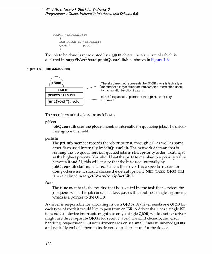
Wind River Network Stack for VxWorks 6Programmer's Guide, Volume 3: Interfaces and Drivers, 6.6
122
STATUS jobQueuePost(JOB_QUEUE_ID jobQueueId,QJOB * pJob)
The job to be done is represented by a QJOB object, the structure of which is declared in target/h/wrn/coreip/jobQueueLib.h as shown in Figure 4-6.
The members of this class are as follows:
pNext jobQueueLib uses the pNext member internally for queueing jobs. The driver may ignore this field.
priInfo The priInfo member records the job priority (0 through 31), as well as some other flags used internally by jobQueueLib. The network daemon that is running the job queue services queued jobs in strict priority order, treating 31 as the highest priority. You should set the priInfo member to a priority value between 0 and 31; this will ensure that the bits used internally by jobQueueLib start out cleared. Unless the driver has a specific reason for doing otherwise, it should choose the default priority NET_TASK_QJOB_PRI (16) as defined in target/h/wrn/coreip/netLib.h.
func The func member is the routine that is executed by the task that services the job queue when this job runs. That task passes this routine a single argument, which is a pointer to the QJOB.
A driver is responsible for allocating its own QJOBs. A driver needs one QJOB for each type of work it would like to post from an ISR. A driver that uses a single ISR to handle all device interrupts might use only a single QJOB, while another driver might use three separate QJOBs for receive work, transmit cleanup, and error handling, respectively. But your driver needs only a small, finite number of QJOBs, and typically embeds them in its driver control structure for the device.
Figure 4-6 The QJOB Class
QJOBpriInfo : UINT32
func(void *) : void
pNext The structure that represents the QJOB class is typically a member of a larger structure that contains information useful to the handler function func( ).
func( ) is passed a pointer to the QJOB as its only argument.

4 Integrating a New Network Interface Driver4.7 Implementing a Network Driver
123
4
A driver initializes its QJOB members at initialization time, typically in its load or start routine, and usually leaves them unchanged after that. The following code snippet shows how a hypothetical “quik” driver might initialize three QJOB members embedded in its driver control structure:
pDrvCtrl->quikTxJob.func = quikTxHandle;pDrvCtrl->quikTxJob.priInfo = NET_TASK_QJOB_PRI;pDrvCtrl->quikRxJob.func = quikRxHandle;pDrvCtrl->quikRxJob.priInfo = NET_TASK_QJOB_PRI;pDrvCtrl->quikErrJob.func = quikErrHandle;pDrvCtrl->quikErrJob.priInfo = NET_TASK_QJOB_PRI;
Here is how the receive interrupt might post the quikRxJob to execute quikRxHandle( ):
jobQueuePost (pDrvCtrl->jobQueueId, &pDrvCtrl->quikRxJob);
Here is how the quikRxHandle( ) job handler routine might recover the driver control structure from its argument, which is a pointer to pDrvCtrl->quickRxJob:
LOCAL void quikRxHandle(QJOB * pJob){QUIK_DRV_CTRL * pDrvCtrl = member_to_object (pJob, QUIK_DRV_CTRL,
quikRxJob);.../* * Do a bounded amount of RX work, then requeue the job if there is* still more work to do; otherwise, reenable RX interrupts, and* return.*/
...}
The member_to_object( ) macro shown above, declared in jobQueueLib.h, converts the address of a member of a structure to the address of the structure itself.
The jobQueuePost( ) routine enqueues the specified job onto the specified job queue, and if necessary unpends the task that services the job queue. That task services any queued jobs in strict priority order. As it services each queued job, it dequeues the job object just before calling the routine specified by the job object’s func member. While the job is enqueued, attempts to requeue it by calling jobQueuePost( ) again will have no effect, but you should avoid such calls. Certainly the driver should not modify a QJOB object while it is enqueued; during this time it is considered to be owned by the job queue itself. To avoid the ISR’s reposting the job when it is enqueued, it may be sufficient for the device to lock device interrupts, when shared interrupts are not a factor. But if other devices can share the interrupt line that the device uses, then it may be necessary for the device
Wind River Network Stack for VxWorks 6Programmer's Guide, Volume 3: Interfaces and Drivers, 6.6
124
to maintain a separate atomic flag to indicate whether the device has already posted the job. For some devices, the device interrupt mask register can play the role of this flag. The job handler routine must take care when it clears the flag and reenables interrupts, so as to avoid races that could either prevent the driver from receiving any further packets, or that could occasionally cause those packets that it receives to languish without the driver servicing them until the arrival of a subsequent packet.
It is possible (and convenient) for a QJOB to repost itself from the QJOB’s handler routine. You cannot cancel a job you have already queued. This may become relevant when an interface shuts down; the driver must use some other mechanism (such as an atomic flag) to wait until the jobs in the queue execute, and then prevent further queuing of the jobs.
Network job queues are usually shared by multiple network interfaces, and by network protocol code also. It is possible to design a driver that starves the network stack and other drivers. When a driver uses taskDelay( ), or any other delay mechanism, in code that executes in the context of a network job queue daemon, the delay prevents the task from processing packets from other interfaces. For this reason, you must carefully consider using delays in the driver. Consider rescheduling the job with another jobQueuePost( ) call instead of delaying. This allows other interfaces, as well as the network stack, to perform other work while the driver is waiting.
Because interrupts are relatively costly in terms of overall system performance, one recommended goal of network drivers is to process many packets before reenabling interrupts. However, to avoid starvation of other interfaces, the driver should enforce a cap on the number of packets that it processes at any one time. If additional packets are available when the cap is reached, the driver can reschedule the receive routine with another call to jobQueuePost( ).
Using Multiple Tasks in SMP Systems with Multiple Interfaces
In SMP systems with more than one network interface, you can increase performance for some network applications that communicate over more than one interface concurrently, by assigning different network devices to post work to different network daemons.
By default, there is only one network daemon created, the task named tNet0. In an SMP system, Wind River suggests increasing the number of network daemons to be equal to the minimum of the number of configured CPUs and the number of network devices, and configuring the network devices so as to distribute work across the available daemons. For example, consider a system with two CPUs, and four network interfaces gei0, gei1, gei2, and gei3. If you configure two network

4 Integrating a New Network Interface Driver4.7 Implementing a Network Driver
125
4
daemons (tNet0 and tNet1), you could assign the even numbered interfaces gei0 and gei2 to tNet0, and the odd numbered interfaces gei1 and gei3 to tNet1. To do this:
■ When configuring the VxWorks image, set the NUM_NET_DAEMONS configuration parameter of the component INCLUDE_NET_DAEMON to 2. This will cause the network start-up code to create two network job queues serviced by two network daemon tasks, tNet0 and tNet1.
■ Optionally, you may also set the parameter NET_DAEMONS_CPU_AFFINITY to TRUE, if you want tNet0 to execute only on CPU 0, and tNet1 to execute only on CPU 1. This is not generally beneficial, although it might help for some workloads. If restricting the CPU affinities of the network daemons in this way, consider also directing each network device’s interrupts to run on the same CPU on which the network daemon that the device uses runs. This is possible to configure for some BSPs and some devices, generally by editing an intrCtlrCpu structure in the hwconf.c file in the BSP directory. See the BSP and VxBus documentation for more information on this topic.
■ At run time, call vxbEndQnumSet( ) to set the network job queue number that each network device will use. In our example case, we leave gei0 and gei2 posting to the default network job queue number 0, and only call vxbEndQnumSet( ) for gei1 and gei3, as follows:
vxbEndQnumSet ("gei", 1, 1); /* make gei1 use tNet1 */vxbEndQnumSet ("gei", 3, 1); /* make gei3 use tNet1 */
vxbEndQnumSet( ) is only supported for VxBus network drivers. It uses the VxBus parameter system to set a parameter containing the job queue that the driver should use. This parameter is only read when a VxBus network device’s start routine is called. If the network device is already started when vxbEndQnumSet( ) is called, vxbEndQnumSet( ) will stop the device for a second and then restart it, so that the change takes effect. If the network device exists but has not started yet (or is presently stopped), vxbEndQnumSet( ) does not stop and restart the device; the change will take effect when the device is started.
This release does not provide a standard mechanism to configure at image build time which network job queue a network device will use. You can modify the usrAppInit( ) routine, or other application-specific start-up code, to call vxbEndQnumSet( ) to configure the network devices that exist in your system to post work to the desired network job queues.
Note that not all network applications will benefit from using multiple network daemons; some applications may actually see decreased performance. Wind River
Wind River Network Stack for VxWorks 6Programmer's Guide, Volume 3: Interfaces and Drivers, 6.6
126
recommends testing with your expected workload when deciding whether and how to configure the use of multiple network daemons.
Passing Frames to the MUX
Write your task-level frame reception routine to construct an M_BLK tuple containing the frame and pass this tuple to the MUX by calling the routine referenced in the receiveRtn field of the END_OBJ structure that represents your device (see A.3.8 END_OBJ, p.297). In the case of ENDs, this routine will have the same prototype as muxReceive( ); in the case of NPT drivers, this routine will have the same prototype as muxTkReceive( ).
Write your reception routine so that if there are no more frames to process, it clears the flag that was set by the ISR to indicate that the receive QJOB is posted. Particularly in cases where a shared interrupt line is possible, this must be done carefully to avoid races.
Handling Transmit-complete Interrupts: Freeing Resources
The transmit-complete interrupt occurs when the device finishes transmitting a packet (at least to the degree that it has DMAed all of the packet data into its internal FIFOs). This interrupt indicates to the driver that it can now recycle the transmit descriptors that it used for the transmission of that packet, and can release the associated packet memory resources.
Your transmit-complete ISR should handle transmit-complete interrupts similarly to how the receive ISR handles packet-reception events: disable further transmit-complete interrupts, and post a net job to do transmit resource clean-up work, such as freeing M_BLK chains, at task level.
The transmit clean-up routine cleans up as many packets as are ready, then reenables device interrupts. The driver may need to maintain an atomic flag that
NOTE: Instead of calling the receiveRtn function pointer directly, you may use the END_RCV_RTN_CALL( ) (END) or TK_RCV_RTN_CALL( ) (NPT) macros, which are defined in endLib.h and which accomplish the same thing. These macros take the same arguments in the same order as muxReceive( ) and muxTkReceive( ) respectively—that is, the same arguments as pDrvCtrl->receiveRtn, but without the need for the initial pDrvCtrl->. (They also presently handle the exceedingly unusual case that pDrvCtrl->receiveRtn is NULL.)
Drivers should generally define the preprocessor macro END_MACROS before including endLib.h, so as to get the inlined version of the APIs that endLib.h provides.
4 Integrating a New Network Interface Driver4.7 Implementing a Network Driver
127
4
indicates whether it has posted the transmit cleanup job, so it can avoid reposting it due to shared interrupts, and to allow graceful shutdown code to wait for the posted job to complete.
The transmit clean-up routine must hold the network device transmit mutex while it is processing the transmit ring and the associated packet M_BLK chain array, to avoid accessing these resources simultaneously with the driver’s xSend( ) routine. At the end of this processing, if the routine has cleaned any transmit descriptors (some drivers also check if the number of available descriptors has reached at least some minimum threshold), and if the “stall flag” is set, the clean-up routine clears the stall flag, and remembers that it should call muxTxRestart( ) after releasing the transmit mutex. The stall flag is a software flag in the driver control structure for the device, that the driver send routine sets if it ever runs out of transmit descriptors (that is, if it stalls) and has to return END_ERR_BLOCK.
After releasing the mutex, if the clean up routine had decided that it should call muxTxRestart( ), it does so. The reason this must be done after releasing the transmit mutex is to avoid semaphore misordering problems. The call to muxTxRestart( ) calls the transmit restart routine of each service that attached to the network device. The transmit restart routine checks whether the service has any packets that were queued for transmission to the network device, that accumulated after the transmit stall; if so, it may call through the MUX to send packets on the device once more. The service transmit restart code takes protocol- specific mutual exclusion, and frequently holds this mutual exclusion around the call that it makes to muxTkSend( ), which establishes a mutex ordering: the service takes the protocol mutual exclusion nested around the driver transmit mutex taken by the driver’s xSend( ) routine. If the driver calls muxTxRestart( ) while holding the device transmit semaphore, the opposite ordering would also happen, and deadlocks would be likely.
The transmit clean-up routine then clears the flag indicating that the transmit clean-up handler is posted and reenables transmit complete interrupts by accessing the appropriate device registers, then returns. There are the same sorts of possible race conditions when this routine clears the transmit clean-up job posted flag and reenables the transmit-complete interrupt as were discussed in the context of packet reception (see Queueing Work to the Network Job Queues, p.121). However, consequences of a transmitted packet languishing for a while before it is freed are generally not as unpleasant as similar languishing of a received but unhandled packet. Some drivers may choose to use a combined job handler routine for both transmit cleanup and receive work.

Wind River Network Stack for VxWorks 6Programmer's Guide, Volume 3: Interfaces and Drivers, 6.6
128
4.8 The Driver Interface with the MUX
This subsection describes the driver entry points and the shared data structures that comprise an driver’s interface with the MUX.
Data Structures Shared by the Driver and the MUX
The core data class for an END or NPT driver is the END object, or END_OBJ. This structure is defined in target/h/end.h (see also A.3.8 END_OBJ, p.297). The driver’s xLoad( ) routine returns a pointer to an object derived from the END_OBJ that it allocates and partially populates. This object supplies the MUX with information that describes the driver as well as a pointer to a NET_FUNCS interface that the driver implements.
Although the driver’s xLoad( ) routine populates much of the END_OBJ object, the MUX sets some of this object’s members when a service binds to the device. Specifically, the MUX maintains the array of services bound to the END_OBJ. When the driver calls the receive routine that the MUX registered by setting the receiveRtn member of the driver’s END_OBJ object, this routine in turn calls the bound service receive routines appropriate for the received packet.
Driver Implementations of the xLoad( ) Routine
A driver must implement an xLoad( ) routine. In a VxBus network driver, since the driver itself passes the address of this routine to muxDevLoad( ), the xLoad( ) routine need not be public; however, for a legacy END driver, the MUX accesses the xLoad( ) routine directly, outside of the driver, and it must be globally visible. It is usually the only globally visible routine for such a driver (see 4.7.1 Adding a Network Driver, p.109).
Before the stack can use a network interface to send and receive frames, it must load the appropriate network device into the MUX, attach services to the network driver, and configure the interface at the service level (for example, by assigning IP addresses). The tUsrRoot task loads network devices into the MUX by calling the muxDevConnect( ) method for any VxBus network drivers or muxDevLoad( ) for all the (non-VxBus) network drivers that are in endDevTbl[ ]. The entries in this table provide all the information needed to call muxDevLoad( ). This includes a reference to the driver’s xLoad( ) routine (or in some cases, a wrapper that the BSP provides that in turn calls the driver’s xLoad( ) routine).
As input, the xLoad( ) routine takes an initialization string, as well as an optional argument provided by the BSP or VxBus driver.
4 Integrating a New Network Interface Driver4.8 The Driver Interface with the MUX
129
4
Write your driver’s xLoad( ) routine as a two-pass algorithm. The MUX calls it twice during the load procedure. In the first pass, the initialization string argument points to a buffer starting with a zero byte. The xLoad( ) routine is expected to check for this empty string and overwrite it with a string containing the prefix name of the device (such as “fei” or “emac”). This informs muxDevLoad( ) about the driver-specific interface name prefix.
The MUX then calls your xLoad( ) routine a second time. This time the initialization string starts with a decimal unit number string, followed by a colon, followed by the contents of the initialization string from the endDevTbl[ ] that tUsrRoot passed to muxDevLoad( ). Your xLoad( ) routine must then return a pointer to the END_OBJ-derived DRV_CTRL object that it creates, or a NULL if the load fails.
VxBus network drivers typically pass NULL to muxDevLoad( ) as the initialization string, and pass the instance’s VXB_DEVICE_ID as the optional argument; the xLoad( ) routine gets all the information it needs from the device ID and the VxBus parameter system. Older network drivers pass an initialization string that is typically a driver-specific colon-separated sequence of driver configuration parameters, and the xLoad( ) routine must tokenize and parse this string, which generally contains such things as the address of memory mapped registers for the device, the number of receive and transmit descriptors to use, the PHY address, and special device flags or options.
A VxBus network driver divides its instance initialization work between its devInstanceInit2( ) routine and its xLoad( ) routine. The division is somewhat arbitrary, but basically anything that depends upon endLib or the MUX may be held off to the xLoad( ) routine. A non-VxBus driver has no devInstanceInit2( ) routine, and so all the work needs to be done in its xLoad( ) routine. The following work is done in either the devInstanceInit2( ) routine, or in the xLoad( ) routine’s second pass:
■ Allocate, zero out, and then populate the DRV_CTRL structure (see A.3.3 DRV_CTRL, p.290).
■ Call END_OBJ_INIT( ) to initialize the END_OBJ core. Among other things, this sets the driver description, and the pointer to the driver’s NET_FUNCS table.
■ Parse and process the initialization string (non-VxBus drivers only).■ Identify and reset the device, putting it into a quiescent state.■ Initialize any necessary private structures.■ Determine the device’s MAC address. This is done in a driver-specific way,
and sometimes in a BSP-specific way.■ Allocate memory for transmit and receive descriptors. Parallel to the transmit
and receive descriptor rings are rings of M_BLK pointers, also for transmit and receive. If these are not part of the driver control structure, the driver must also
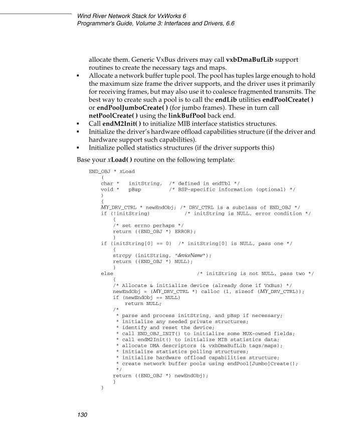
Wind River Network Stack for VxWorks 6Programmer's Guide, Volume 3: Interfaces and Drivers, 6.6
130
allocate them. Generic VxBus drivers may call vxbDmaBufLib support routines to create the necessary tags and maps.
■ Allocate a network buffer tuple pool. The pool has tuples large enough to hold the maximum size frame the driver supports, and the driver uses it primarily for receiving frames, but may also use it to coalesce fragmented transmits. The best way to create such a pool is to call the endLib utilities endPoolCreate( ) or endPoolJumboCreate( ) (for jumbo frames). These in turn call netPoolCreate( ) using the linkBufPool back end.
■ Call endM2Init( ) to initialize MIB interface statistics structures.■ Initialize the driver’s hardware offload capabilities structure (if the driver and
hardware support such capabilities).■ Initialize polled statistics structures (if the driver supports this)
Base your xLoad( ) routine on the following template:
END_OBJ * xLoad(char * initString, /* defined in endTbl */void * pBsp /* BSP-specific information (optional) */){MY_DRV_CTRL * newEndObj; /* DRV_CTRL is a subclass of END_OBJ */if (!initString) /* initString is NULL, error condition */
{/* set errno perhaps */return ((END_OBJ *) ERROR);}
if (initString[0] == 0) /* initString[0] is NULL, pass one */{strcpy (initString, "deviceName");return ((END_OBJ *) NULL);}
else /* initString is not NULL, pass two */{/* Allocate & initialize device (already done if VxBus) */newEndObj = (MY_DRV_CTRL *) calloc (1, sizeof (MY_DRV_CTRL));if (newEndObj == NULL)
return NULL;/** parse and process initString, and pBsp if necessary;* initialize any needed private structures;* identify and reset the device;* call END_OBJ_INIT() to initialize some MUX-owned fields;* call endM2Init() to initialize MIB statistics data;* allocate DMA descriptors (& vxbDmaBufLib tags/maps);* initialize statistics polling structures;* initialize hardware offload capabilities structure;* create network buffer pools using endPool[Jumbo]Create();*/return ((END_OBJ *) newEndObj);}
}

4 Integrating a New Network Interface Driver4.8 The Driver Interface with the MUX
131
4
Driver Implementations of the NET_FUNCS Interface
Table 4-2 lists the entry points of the NET_FUNCS interface that drivers implement and expose to the MUX. In this book, these routines have a generic “x” prefix, but in practice this prefix is usually replaced with a driver-specific identifier, such as “ln7990” for the Lance Ethernet driver.
Table 4-2 NET_FUNCS Interface Routines
Routine Description
xStart( ) Enable reception and transmission for the device.
xStop( ) Deactivate the network device.
xUnload( ) Release a device, or a port on a device, from the MUX.
xIoctl( ) Support various ioctl commands.
xSend( ) Accept data from the MUX and send it on to the physical layer.
xMCastAddrAdd( ) Add a multicast address to the list of those registered for the device.
xMCastAddrDel( ) Remove a multicast address from those registered for the device.
xMCastAddrGet( ) Retrieve a list of multicast addresses registered for a device.
xPollSend( ) Send frames in polled mode rather than interrupt-driven mode. (Poll mode should only be used for debugging.)
xPollRcv( ) Receive frames in polled mode rather than interrupt-driven mode. Poll mode should only be used for debugging. For details, see 4.3.3 Polled Mode – For Debugging Only, p.92.
xFormAddress( ) Add addressing information to a packet.
xPacketDataGet( ) Separate the addressing information and data in a packet.
xAddrGet( ) Extract the addressing information from a packet.
xEndBind( ) Exchange data with the network service at bind time. (Optional)

Wind River Network Stack for VxWorks 6Programmer's Guide, Volume 3: Interfaces and Drivers, 6.6
132
xStart( )
The driver’s xStart( ) routine does whatever is necessary to make the driver active and available. For instance, it should do the following:
■ Register your device driver’s interrupt service routine by calling sysIntConnect( ), if this has not been done earlier in the load routine or in devInstanceInit2( ).
■ VxBus network drivers should reread parameters that might be expected to change between device stops and starts, for instance the parameter specifying the network job queue to which the driver posts work for the device.
■ Configure the device for packet reception and transmission.
■ Populate the receive ring and parallel receive M_BLK pointer ring with tuples from the device’s network buffer pool.
■ Initialize the transmit ring.
■ Enable device interrupts at the board/interrupt controller level as well as at the device-specific level.
■ Appropriately set the device registers that finally enable reception and transmission.
■ Set the PHY to the desired mode.
For VxBus network drivers, the driver’s muxDevConnect( ) method calls muxDevStart( ) after calling muxDevLoad( ); for other network drivers, the start-up code calls muxDevStart( ) after muxDevLoad( ). In either case, muxDevStart( ) passes xStart( ) the unique interface identifier that the driver’s xLoad( ) routine returned.
As with xLoad( ), the MUX makes this call for each port that it activates within the driver.
An example template for the xStart( ) routine follows:
STATUS xStart(END_OBJ * pEND, /* END object */){x_DRV_CTRL * pDrvCtrl = (x_DRV_CTRL *) pEnd;/* * Some drivers may require additional mutual exclusion beyond the * transmit semaphore. If so, be sure to observe proper mutex ordering.*/
END_TX_SEM_TAKE (&pDrvCtrl->end, WAIT_FOREVER);

4 Integrating a New Network Interface Driver4.8 The Driver Interface with the MUX
133
4
if ((pDrvCtrl->end.flags & IFF_UP) == 0){/* * - Reread selected device parameters, such as the job queue ID. * - Connect the driver's ISRs, if not already done. * - Initialize RX descriptor ring; set each descriptor to point to * a buffer from a tuple from the device network buffer pool. * - Initialize TX ring as needed. * - Configure the device according to current settings. * - Endable device interrupts. * - Enable transmission and reception. * - Set desired PHY mode.*/pDrvCtrl->end.flags |= (IP_IFF_UP | IP_IFF_RUNNING); }
END_TX_SEM_GIVE (&pDrvCtrl->end);return (OK);}
Write this routine to return OK, or ERROR in which case it should set errno appropriately.
xStop( )
The driver’s xStop( ) routine halts a network device, putting it into a quiescent state in which it does not generate interrupts. It also does the following:
■ Waits for any network jobs which may be outstanding for the device to complete, and arranges that more network jobs will not be posted nor will device interrupts be reenabled.
■ Disconnects any driver ISRs that the xStart( ) routine connected.
■ Frees outstanding transmitted packets that have not been returned to the stack, and returns tuples associated with the device’s receive ring to the device network buffer pool. (This is done so that if the buffer pool is shared between multiple devices, the other devices have access to the buffers while the current device is stopped.) Otherwise, the xStop( ) routine does not release data structures that were allocated in the xLoad( ) routine or in devInstanceInit2( ).
The MUX passes xStop( ) the END_OBJ pointer returned by the driver’s xLoad( ) routine. xStop( ) is considered a synchronous routine, that is, it should not return until the device has been fully quiesced.
An xStop( ) template follows:
STATUS xStop(END_OBJ * pEND, /* END object */){

Wind River Network Stack for VxWorks 6Programmer's Guide, Volume 3: Interfaces and Drivers, 6.6
134
x_DRV_CTRL * pDrvCtrl = (x_DRV_CTRL *) pEnd;
END_TX_SEM_TAKE (&pDrvCtrl->end, WAIT_FOREVER);if (pDrvCtrl->end.flags & IFF_UP)
{pEND->flags &= ~(IFF_UP | IFF_RUNNING); /* * - Prevent any jobs in progress from reenabling interrupts * - Disable device interrupts * - Wait for any outstanding jobs to complete; ensure no others are * posted. * - Disable packet reception and transmission. * - Clean the transmit M_BLK ring, freeing any packets to the stack. * - Clean RX tuple ring, returning tuples to network buffer pool. * - If using the recycle cache, call endMCacheFlush(). * - If the driver ISRs were connected in xStart(), disconnect them*/}
END_TX_SEM_GIVE (&pDrvCtrl->end);return (OK); }
Write this routine to return OK.
xUnload( )
The MUX calls your driver’s xUnload( ) when a system application calls muxDevUnload( ). A VxBus network driver may itself call muxDevUnload( ) in response to a call to its vxbDrvUnlink( ) method, asking it to unlink an instance.
When muxDevUnload( ) is called, it checks if the specified device is still up. If so, muxDevUnload( ) calls the driver’s xStop( ) routine for the device. Next, it calls the shutdown routines for each service that bound to the device; the service shutdown routine must in turn call muxUnbind( ) to unbind itself from the device. Finally, muxDevUnload( ) calls the xUnload( ) routine for the device. (See Figure 4-4.)
In its xUnload( ) routine, your driver is responsible for doing whatever it takes to release all resources associated with the device that were created or allocated during the driver’s xLoad( ) routine. (For non-VxBus network drivers, this would include all resources associated with the device. For VxBus network drivers, resources allocated in the devInstanceInit2( ) routine, before the xLoad( ) routine is called, do not need to be freed.) These resources may include memory, the device network pool and all its buffers, kernel objects such as semaphores associated with the device, and so forth.
The DRV_CTRL structure for the device, which starts with an embedded END_OBJ, is a special case:

4 Integrating a New Network Interface Driver4.8 The Driver Interface with the MUX
135
4
– If the driver’s xUnload( ) routine returns OK, muxDevUnload( ) will itself free the END_OBJ, which frees the driver control structure.
– If the driver’s xUnload( ) routine returns any other value, muxDevUnload( ) will not attempt to free the END_OBJ; that becomes the driver’s responsibility.
– If there is no error condition, but the driver wishes to free the END_OBJ itself, the xUnload( ) routine should return EALREADY.
– Any return value other than OK or EALREADY indicates an error condition, and an error message will be logged.
– Generally, VxBus network driver xUnload( ) routines should return EALREADY, since the driver control structure is typically needed in the driver’s vxbDrvUnlink( ) method after the call to muxDevUnload( ). Also, muxDevUnload( ) might be called for a VxBus network device outside of the context of the vxbDrvUnlink( ) method; in that case also, the instance still exists from the point of view of VxBus, and so the driver’s control structure for the instance must not be freed yet.
The xUnload( ) routine must free the device network buffer pool:
– For pools created with endPoolCreate( ) or endPoolJumboCreate( ), this is done by calling endPoolDestroy( ).
– Pools created using netPoolCreate( ) may be freed by calling netPoolRelease( ). Calling netPoolRelease( ) causes the system to free a pool after the stack releases all network pool resources that it is holding from that pool.
– For any pools that the driver created using netPoolInit( ), there is no such safe pool release routine, and the driver must ensure that all tuples have been returned to the driver pool before it returns successfully from xUnload( ). If it cannot do so, the driver does not properly support unloading the device.
– Wind River recommends that drivers use endPoolCreate( ), endPoolJumboCreate( ), or netPoolCreate( ), instead of netPoolInit( ), to create driver memory pools.
xUnload( ) is a device-specific call. If the driver has any resources that it shares among all of its device instances, it must not free these shared resources until the MUX calls the driver’s xUnload( ) routine for each of these devices.

Wind River Network Stack for VxWorks 6Programmer's Guide, Volume 3: Interfaces and Drivers, 6.6
136
The xUnload( ) prototype is:
STATUS xUnload(END_OBJ * pEND /* END object */)
xIoctl( )
Network drivers are not installed into the VxWorks I/O system using iosDrvInstall( ), and so they do not directly support the ioctl( ) function, which passes an integer “file descriptor” as its first argument. However, the MUX supports an ioctl-like interface, muxIoctl( ), that a caller can use to request miscellaneous device-specific services from network drivers (see A.2.13 muxIoctl( ), p.272). The ioctl command codes in this interface begin with “EIOC” and are listed in the file target/h/endCommon.h.
Some protocol stacks may translate certain socket ioctl commands into other “EIOC” ioctl codes that they then pass to the MUX. However, the translation need not be one-to-one, and there is not any protocol stack-independent way to call MUX ioctl commands using a socket file descriptor. Applications that need to call MUX ioctls should bind as a service to a network driver, and pass the binding cookie as the first argument to muxIoctl( ); or failing that, obtain a pseudo-binding cookie by calling muxTkCookieGet( ) and use that when calling muxIoctl( ). Some MUX ioctl calls are handled by the MUX itself, but most are passed down by muxIoctl( ) to the network driver’s xIoctl( ) routine.
Any variety of network driver may need to support MUX ioctl commands, particularly if it is to interface with the existing IP network service sublayer. See Table 4-3 for a list of commonly-used ioctl commands.
An NPT driver must support the command EIOCGNPT. The MUX (and sometimes a network service) uses this command to determine if a driver is of the NPT variety. All the driver needs to do upon receiving this command is to return OK, indicating success. Non-NPT drivers must return EINVAL when they receive the EIOCGNPT ioctl command (as any driver should do when it receives a MUX ioctl that it does not understand).
NOTE: Wind River assigns MUX ioctl command codes according to the scheme defined in target/h/sys/ioctl.h, using the macros _IOR( ), _IOW( ), _IORW( ). The n argument to these macros becomes the low-order byte of the command code. Low-order byte values in the range 0-127 are reserved for Wind River use. Choose n values in the range 128-255 to avoid possible conflict with new Wind River codes.

4 Integrating a New Network Interface Driver4.8 The Driver Interface with the MUX
137
4
The MUX passes the xIoctl( ) routine three arguments:
■ the END_OBJ pointer that the driver returned from xLoad( )
■ the ioctl command being issued (for instance, one from Table 4-3)
■ an additional argument, often a pointer to a data buffer for additional data given in the command or for data to be returned on completion of the command
While this argument is prototyped as a caddr_t (the equivalent of a char *), the actual type passed depends upon the particular MUX ioctl command. For the commands EIOCSADDR, EIOCGADDR, EIOCMULTIADD, and EIOCMULTIDEL that pass link-layer addresses, the lengths of these addresses must be implicitly known to the driver and to the attached services that call muxIoctl( ). For Ethernet drivers, the addresses are 6 bytes long.
The following xIoctl( ) template example is modelled after the geiEndIoctl( ) routine of the gei825xxVxbEnd.c driver:
LOCAL int xIoctl(END_OBJ * pEND, /* END Object */int command, /* ioctl command */caddr_t data /* holds response from command */){MY_DRV_CTRL * pDrvCtrl;END_MEDIALIST * mediaList;END_CAPABILITIES * hwCaps;END_MEDIA * pMedia;INT32 value;int error = OK
pDrvCtrl = (MY_DRV_CTRL *) pEnd;if (command != EIOCPOLLSTART && command != EIOCPOLLSTOP)
semTake (pDrvCtrl->xDevSem, WAIT_FOREVER);
switch (command){
/****** if this is an NPT driver, add the following section:
case EIOCGNPT:
! WARNING: The muxIoctl( ) routine handles the multicast address add, delete, and list-get ioctl commands (EIOCMULTIADD, EIOCMULTIDEL, EIOCMULTIGET) by calling the corresponding mCastAddrAdd( ), mCastAddrDel( ), or mCastAddrGet( ) functions from the driver NET_FUNCS structure. Do not be tempted to support only the multicast table management ioctls and not the corresponding NET_FUNCS functions.
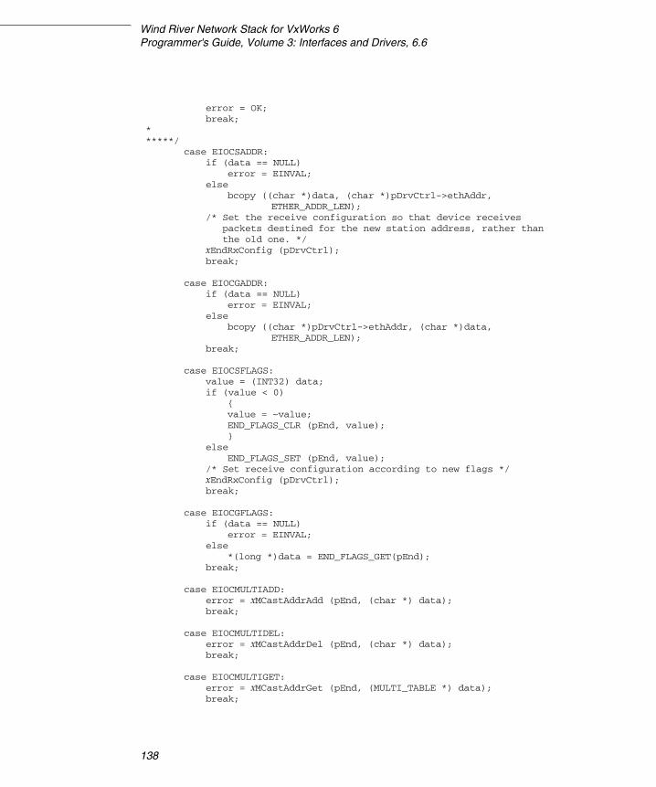
Wind River Network Stack for VxWorks 6Programmer's Guide, Volume 3: Interfaces and Drivers, 6.6
138
error = OK;break;
******/
case EIOCSADDR:if (data == NULL)
error = EINVAL;else
bcopy ((char *)data, (char *)pDrvCtrl->ethAddr,ETHER_ADDR_LEN);
/* Set the receive configuration so that device receivespackets destined for the new station address, rather thanthe old one. */
xEndRxConfig (pDrvCtrl);break;
case EIOCGADDR:if (data == NULL)
error = EINVAL;else
bcopy ((char *)pDrvCtrl->ethAddr, (char *)data,ETHER_ADDR_LEN);
break;
case EIOCSFLAGS:value = (INT32) data;if (value < 0)
{value = ~value;END_FLAGS_CLR (pEnd, value);}
elseEND_FLAGS_SET (pEnd, value);
/* Set receive configuration according to new flags */xEndRxConfig (pDrvCtrl);break;
case EIOCGFLAGS:if (data == NULL)
error = EINVAL;else
*(long *)data = END_FLAGS_GET(pEnd);break;
case EIOCMULTIADD:error = xMCastAddrAdd (pEnd, (char *) data);break;
case EIOCMULTIDEL:error = xMCastAddrDel (pEnd, (char *) data);break;
case EIOCMULTIGET:error = xMCastAddrGet (pEnd, (MULTI_TABLE *) data);break;
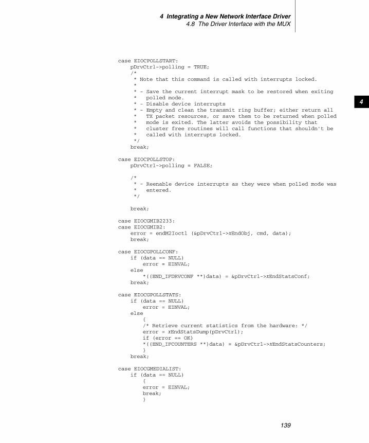
4 Integrating a New Network Interface Driver4.8 The Driver Interface with the MUX
139
4
case EIOCPOLLSTART:pDrvCtrl->polling = TRUE;/* * Note that this command is called with interrupts locked.** - Save the current interrupt mask to be restored when exiting* polled mode.* - Disable device interrupts* - Empty and clean the transmit ring buffer; either return all* TX packet resources, or save them to be returned when polled* mode is exited. The latter avoids the possibility that* cluster free routines will call functions that shouldn't be* called with interrupts locked.*/break;
case EIOCPOLLSTOP:pDrvCtrl->polling = FALSE;
/** - Reenable device interrupts as they were when polled mode was * entered.*/
break;
case EIOCGMIB2233:case EIOCGMIB2:
error = endM2Ioctl (&pDrvCtrl->xEndObj, cmd, data);break;
case EIOCGPOLLCONF:if (data == NULL)
error = EINVAL;else
*((END_IFDRVCONF **)data) = &pDrvCtrl->xEndStatsConf;break;
case EIOCGPOLLSTATS:if (data == NULL)
error = EINVAL;else
{/* Retrieve current statistics from the hardware: */error = xEndStatsDump(pDrvCtrl);if (error == OK)*((END_IFCOUNTERS **)data) = &pDrvCtrl->xEndStatsCounters;}
break;
case EIOCGMEDIALIST:if (data == NULL)
{error = EINVAL;break;}
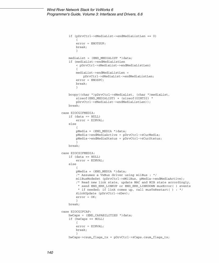
Wind River Network Stack for VxWorks 6Programmer's Guide, Volume 3: Interfaces and Drivers, 6.6
140
if (pDrvCtrl->xMediaList->endMediaListLen == 0){error = ENOTSUP;break;}
mediaList = (END_MEDIALIST *)data;if (mediaList->endMediaListLen
< pDrvCtrl->xMediaList->endMediaListLen){mediaList->endMediaListLen =
pDrvCtrl->xMediaList->endMediaListLen;error = ENOSPC;break;}
bcopy((char *)pDrvCtrl->xMediaList, (char *)mediaList,sizeof(END_MEDIALIST) + (sizeof(UINT32) *pDrvCtrl->xMediaList->endMediaListLen));
break;
case EIOCGIFMEDIA:if (data == NULL)
error = EINVAL;else
{pMedia = (END_MEDIA *)data;pMedia->endMediaActive = pDrvCtrl->xCurMedia;pMedia->endMediaStatus = pDrvCtrl->xCurStatus;}
break;
case EIOCSIFMEDIA:if (data == NULL)
error = EINVAL;else
{pMedia = (END_MEDIA *)data;/* Assumes a VxBus driver using miiBus : */miiBusModeSet (pDrvCtrl->xMiiBus, pMedia->endMediaActive);/* Read new link state, update MAC and MIB state accordingly, * send END_ERR_LINKUP or END_ERR_LINKDOWN muxError( ) events * if needed; if link comes up, call muxTxRestart( ) : */xLinkUpdate (pDrvCtrl->xDev);error = OK;}
break;
case EIOCGIFCAP:hwCaps = (END_CAPABILITIES *)data;if (hwCaps == NULL)
{error = EINVAL;break;}
hwCaps->csum_flags_tx = pDrvCtrl->xCaps.csum_flags_tx;

4 Integrating a New Network Interface Driver4.8 The Driver Interface with the MUX
141
4
hwCaps->csum_flags_rx = pDrvCtrl->xCaps.csum_flags_rx;hwCaps->cap_available = pDrvCtrl->xCaps.cap_available;hwCaps->cap_enabled = pDrvCtrl->xCaps.cap_enabled;break;
case EIOCSIFCAP:hwCaps = (END_CAPABILITIES *)data;if (hwCaps == NULL)
{error = EINVAL;break;}pDrvCtrl->xCaps.cap_enabled = hwCaps->cap_enabled;break;
case EIOCGIFMTU:if (data == NULL)
error = EINVAL;else
*(INT32 *)data = pEnd->mib2Tbl.ifMtu;break;
case EIOCSIFMTU:value = (INT32)data;if (value <= 0 || value > pDrvCtrl->xMaxMtu)
{error = EINVAL;break;}
pEnd->mib2Tbl.ifMtu = value;if (pEnd->pMib2Tbl != NULL)
pEnd->pMib2Tbl->m2Data.mibIfTbl.ifMtu = value;break;
case EIOCGRCVJOBQ:if (data == NULL)
{error = EINVAL;break;
}
qinfo = (END_RCVJOBQ_INFO *)data;nQs = qinfo->numRcvJobQs;qinfo->numRcvJobQs = 1;if (nQs < 1)
error = ENOSPC;else
qinfo->qIds[0] = pDrvCtrl->xJobQueue;break;
default:error = EINVAL;break;
}
if (cmd != EIOCPOLLSTART && cmd != EIOCPOLLSTOP)
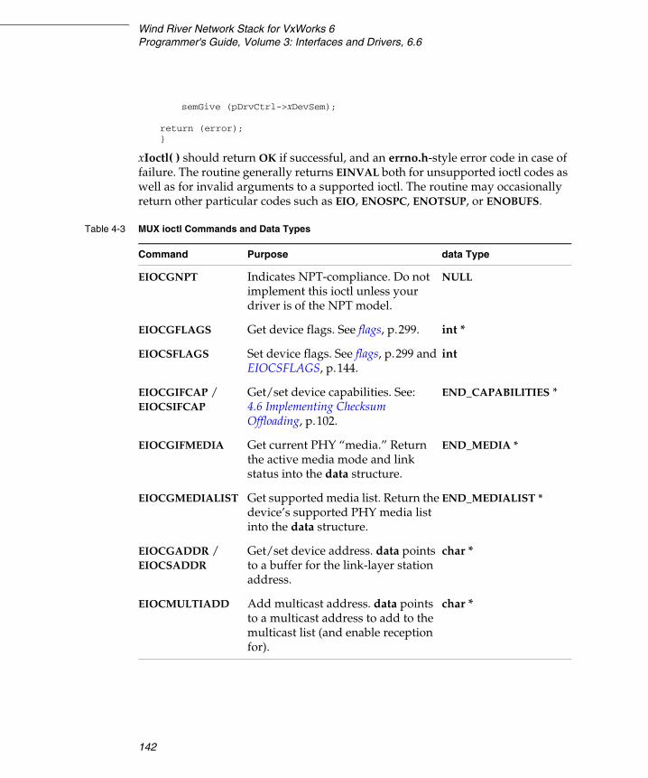
Wind River Network Stack for VxWorks 6Programmer's Guide, Volume 3: Interfaces and Drivers, 6.6
142
semGive (pDrvCtrl->xDevSem);
return (error);}
xIoctl( ) should return OK if successful, and an errno.h-style error code in case of failure. The routine generally returns EINVAL both for unsupported ioctl codes as well as for invalid arguments to a supported ioctl. The routine may occasionally return other particular codes such as EIO, ENOSPC, ENOTSUP, or ENOBUFS.
Table 4-3 MUX ioctl Commands and Data Types
Command Purpose data Type
EIOCGNPT Indicates NPT-compliance. Do not implement this ioctl unless your driver is of the NPT model.
NULL
EIOCGFLAGS Get device flags. See flags, p.299. int *
EIOCSFLAGS Set device flags. See flags, p.299 and EIOCSFLAGS, p.144.
int
EIOCGIFCAP /EIOCSIFCAP
Get/set device capabilities. See: 4.6 Implementing Checksum Offloading, p.102.
END_CAPABILITIES *
EIOCGIFMEDIA Get current PHY “media.” Return the active media mode and link status into the data structure.
END_MEDIA *
EIOCGMEDIALIST Get supported media list. Return the device’s supported PHY media list into the data structure.
END_MEDIALIST *
EIOCGADDR /EIOCSADDR
Get/set device address. data points to a buffer for the link-layer station address.
char *
EIOCMULTIADD Add multicast address. data points to a multicast address to add to the multicast list (and enable reception for).
char *

4 Integrating a New Network Interface Driver4.8 The Driver Interface with the MUX
143
4
EIOCMULTIDEL Delete multicast address. data points to a multicast address to remove from the multicast list (and no longer receive).
char *
EIOCMULTIGET Get multicast list. data is a pointer to a table that the driver fills with the multicast addresses in its multicast reception list.
MULTI_TABLE *
EIOCPOLLSTART Put device in polled mode. NULL
EIOCPOLLSTOP Put device in interrupt mode (exit polled mode).
NULL
EIOCGMTU Get the link MTU. INT32 *
EIOCSIFMTU Set the link MTU. INT32
EIOCGRCVJOBQ Get the queue ID of the job queue the device uses to post work.
END_RCVJOBQ_INFO *
EIOCQUERY Retrieve the bind routine (see 4.7.3 Responding to Network Service Bind Calls, p.117 and EIOCQUERY, p.144).
END_QUERY *
EIOCGHDRLEN Get the size of the datalink header (if this is not supported, you can assume a 14-byte header).
int *
EIOCGMIB2 Get RFC 1213 MIB information from the driver. Call endM2Ioctl( ) to handle this.
M2_INTERFACETBL *
EIOCGMIB2233 Get RFC 2233 MIB information from the driver. Call endM2Ioctl( ) to handle this.
M2_ID **
EIOCGPOLLCONF Get statistics polling configuration. END_IFDRVCONF **
EIOCGPOLLSTATS Get the current poll statistics counts.END_IFCOUNTERS **
Table 4-3 MUX ioctl Commands and Data Types (cont’d)
Command Purpose data Type
Wind River Network Stack for VxWorks 6Programmer's Guide, Volume 3: Interfaces and Drivers, 6.6
144
EIOCSFLAGS
The EIOCSFLAGS MUX ioctl is called by upper layers of the stack to set a small number of device flags (values defined in target/h/wrn/coreip/net/if.h), such as IFF_PROMISC or IFF_ALLMULTI, that may be administratively controllable. (IFF_UP is not directly administratively controllable; a network device should be brought up or down by calling muxDevStart( ) or muxDevStop( ). Other flags like IFF_BROADCAST, IFF_SIMPLEX, IFF_MULTICAST that refer to general characteristics of the device are likewise not administratively controllable.)
The caller may use the EIOCSFLAGS ioctl either to clear or to set bit flags. If the most significant bit of the integer argument to the ioctl is clear, so that the argument appears non-negative as a signed integer, the intent is to set any of the other bits that are on. On the other hand, if the most significant bit in the argument is set, so that the argument appears negative, the intent is to clear bits: specifically, to clear the bits that are set in the ones-complement of the argument. For example, to clear IFF_PROMISC, the argument would be ~IFF_PROMISC, while to set IFF_PROMISC and IFF_ALLMULTI, the argument would just be (IFF_PROMISC | IFF_ALLMULTI). The use of the most significant bit to determine whether to set or clear means that you cannot define this bit as a flag with a different purpose.
EIOCQUERY
In the case where command is EIOCQUERY, data points to an END_QUERY structure (see A.3.10 END_QUERY, p.301). The caller sets the query field of this structure to the type of query (for instance, END_BIND_QUERY), and the queryLen field to the size of the queryData buffer. Upon receipt of an EIOCQUERY command, your xIoctl( ) routine should either copy data into this queryData buffer, or return an error value such as EINVAL.
Your driver is not required to support EIOCQUERY queries.
xSend( )
The MUX calls this routine when the network service issues a send request. The MUX passes in a reference to an M_BLK chain representing the data the routine is to send. This routine is responsible for sending this data over the device (see 4.5 Transmitting Data, p.95 for a more-thorough discussion of how a driver transmits data).

4 Integrating a New Network Interface Driver4.8 The Driver Interface with the MUX
145
4
This routine should return one of the following:
OKif the send succeeds
END_ERR_BLOCKif the send cannot complete because of a transient condition such as all transmit descriptors being in use
This is normal transmit flow control, and is not considered an error. If the send routine returns END_ERR_BLOCK, this means that the driver’s transmit side is stalled, and the driver must arrange to call muxTxRestart( ) when it has sufficient resources to complete the send (see Figure 4-7). The muxTxRestart( ) call must be done in the context of the driver’s network job queue task, with no mutexes held.
The driver may require that a certain high-water-mark of transmit resources be available before it calls muxTxRestart( ). However, it must call muxTxRestart( ) at some point on its own initiative; it cannot rely upon network services making further send calls after a transmit stall otherwise.
When the send routine returns END_ERR_BLOCK, the stack still owns the M_BLK chain describing the packet, and the driver should not free it. If the send routine returns any other value, the driver takes ownership of the M_BLK chain and must arrange to free it soon after transmission completes.
ERRORin which case the driver should set errno appropriately
This case is exceedingly unusual, and indicates a problem with the packet, the driver, or the device that would prevent the packet from ever being successfully sent. The driver must free the packet.
NOTE: The current release of the Wind River Network Stack’s IP stack passes only packets consisting of a single M_BLK tuple, that is, a single contiguous segment, to the MUX for transmission. However, because this is not guaranteed for other protocols and services, network drivers should continue to support transmission of packets described by a chain of more than one M_BLK tuple.

Wind River Network Stack for VxWorks 6Programmer's Guide, Volume 3: Interfaces and Drivers, 6.6
146
ENDs and NPT drivers implement this routine differently:
END Implementation
In the case of an END, the data in pPkt is a link-level frame; the needed link header is already present.
The prototype of the xSend( ) routine in an END is:
STATUS xSend(END_OBJ * pEND, /* END object */M_BLK_ID pPkt /* M_BLK chain containing the frame */)
NPT Implementation
In the case of an NPT driver, the data in pPkt is a packet, usually without a link header attached. In this routine, an NPT driver must prepend the link-level header to this packet before sending it.
Figure 4-7 Implementing Flow Control
Service MUX Driver
mux[Tk]Send( )xSend( )
END_ERR_BLOCK
END_ERR_BLOCK
muxTxRestart( )xStackRestartRtn( )
mux[Tk]Send( )xSend( )
OKOK

4 Integrating a New Network Interface Driver4.8 The Driver Interface with the MUX
147
4
The prototype of the xSend( ) routine in an NPT driver is:
STATUS xSend(END_OBJ * pEND, /* END object */M_BLK_ID pPkt, /* network packet to transmit */char * dstAddr, /* destination MAC address */int netSvcType, /* network service type, in network byte order */void * pSpare /* optional network service data */)
When dstAddr is non-NULL, it points to a buffer containing the destination link-level address for the packet. The NPT driver xSend( ) routine must use this, together with the netSvcType parameter and its knowledge of the interface’s own station address (the source address) to construct a link header for the packet.
There may or may not be space available at the start of the cluster containing the start of the packet to prefix the full MAC header. The M_PREPEND( ) macro, defined in target/h/wrn/coreip/net/mbuf.h, will attempt to prefix sufficient space. If there is enough existing leading space in the cluster and the cluster is not shared by more than one code path, M_PREPEND( ) will simply adjust the M_BLK pointers, otherwise it will try to allocate a new tuple out of the legacy “network stack data pool” (which must be configured into the image, as part of the component INCLUDE_NET_POOL).
Some NPT drivers may prefer to use their own mechanisms to allocate space for a link header. If the driver cannot successfully prepend a link header, it must either free the packet using netMblkClChainFree( ) and return ERROR, or, if the driver can guarantee that it will call muxTxRestart( ) later when more resources are available, it may return END_ERR_BLOCK. If the driver returns END_ERR_BLOCK, it must return the packet to its original state (for instance, if it prepended a link header it must remove this link header). Some previous stack versions allowed a driver to set the M_HEADER/M_PROMISC flag in the lead M_BLK rather than removing the prepended link header, but the current protocol stacks do not support this usage.
When dstAddr is NULL, the packet already has a link header, and the NPT driver xSend( ) routine should not prefix another.
The pSpare argument is usually NULL. This argument is passed through the MUX from the pSpareData argument passed by the service calling muxTkSend( ). To use this parameter at all, the NPT driver must have knowledge of, and be able to identify, the sending protocol (perhaps by using the netSvcType parameter); and must agree with the sending protocol on the interpretation of the parameter. Wind River protocols and drivers have to date established no conventions for use of this parameter.
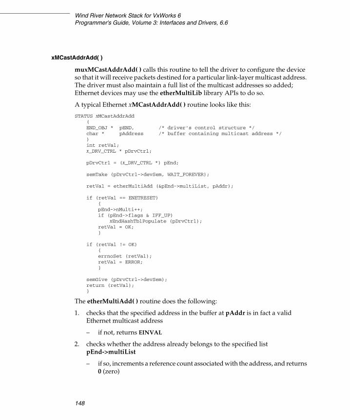
Wind River Network Stack for VxWorks 6Programmer's Guide, Volume 3: Interfaces and Drivers, 6.6
148
xMCastAddrAdd( )
muxMCastAddrAdd( ) calls this routine to tell the driver to configure the device so that it will receive packets destined for a particular link-layer multicast address. The driver must also maintain a full list of the multicast addresses so added; Ethernet devices may use the etherMultiLib library APIs to do so.
A typical Ethernet xMCastAddrAdd( ) routine looks like this:
STATUS xMCastAddrAdd(END_OBJ * pEND, /* driver's control structure */char * pAddress /* buffer containing multicast address */)int retVal;x_DRV_CTRL * pDrvCtrl;
pDrvCtrl = (x_DRV_CTRL *) pEnd;
semTake (pDrvCtrl->devSem, WAIT_FOREVER);
retVal = etherMultiAdd (&pEnd->multiList, pAddr);
if (retVal == ENETRESET){pEnd->nMulti++;if (pEnd->flags & IFF_UP)
xEndHashTblPopulate (pDrvCtrl);retVal = OK;}
if (retVal != OK){errnoSet (retVal);retVal = ERROR;}
semGive (pDrvCtrl->devSem);return (retVal);}
The etherMultiAdd( ) routine does the following:
1. checks that the specified address in the buffer at pAddr is in fact a valid Ethernet multicast address
– if not, returns EINVAL
2. checks whether the address already belongs to the specified list pEnd->multiList
– if so, increments a reference count associated with the address, and returns 0 (zero)

4 Integrating a New Network Interface Driver4.8 The Driver Interface with the MUX
149
4
3. attempts to allocate a buffer for the new address
– if unsuccessful, returns ENOBUFS
– if successful, adds the new address is added to the list with reference count 1 and returns ENETRESET, which lets the driver know that it should increment the multicast address count and reconfigure the hardware to receive packets destined to the new multicast address
In this example code, the driver does this by calling its routine xEndHashTblPopulate( ). Different devices have different multicast filtering capabilities, but generally you should program your device to receive packets for every multicast address in pEnd->multiList, and for as few others as possible. (An exception is that if the IFF_ALLMULTI flag has been set, the device should receive packets destined to any multicast address.)
A driver for a device that is not multicast capable should clear IFF_MULTICAST in its flags (see flags, p.299), and should also provide dummy mCastAddrAdd( ), mCastAddrDel( ), and mCastAddrGet( ) routines in its NET_FUNCS interface that simply set errno to ENOTSUP and return ERROR.
Drivers for multicast-capable devices using non-Ethernet MAC addresses cannot use etherMultiLib, and will have to implement their own methods to manage multicast address lists.
xMCastAddrDel( )
This routine removes a previously registered multicast address from the list that the driver maintains. It does the reverse of xMCastAddrAdd( ).
A typical Ethernet xMCastAddrDel( ) implementation looks like this:
STATUS xMCastAddrDel(END_OBJ * pEND, /* END object */char * pAddress /* buffer with the multicast address to be removed */){int retVal;x_DRV_CTRL * pDrvCtrl;
pDrvCtrl = (x_DRV_CTRL *) pEnd;
semTake (pDrvCtrl->devSem, WAIT_FOREVER);
retVal = etherMultiDel (&pEnd->multiList, pAddr);
if (retVal == ENETRESET){pEnd->nMulti--;

Wind River Network Stack for VxWorks 6Programmer's Guide, Volume 3: Interfaces and Drivers, 6.6
150
if (pEnd->flags & IFF_UP)xEndHashTblPopulate (pDrvCtrl);
retVal = OK;}
if (retVal != OK){errnoSet (retVal);retVal = ERROR;}
semGive (pDrvCtrl->devSem);return (retVal);}
The routine is very similar to xMCastAddrAdd( ), except that it calls etherMultiDel( ) instead of etherMultiAdd( ), and decrements pEnd->nMulti rather than incrementing it, if etherMultiDel( ) returns ENETRESET.
etherMultiDel( ) checks the specified list pEnd->multiList for the specified link-layer address at pAddr. If the address is not present in the list, etherMultiDel( ) returns ENXIO. Otherwise, etherMultiDel( ) decrements the reference count associated with the address.
If the reference count is still nonzero, etherMultiDel( ) simply returns OK. Otherwise, it removes the address from the list and frees the buffer that etherMultiAdd( ) allocated to hold it, and returns ENETRESET. An ENETRESET return value indicates to the driver that the address list has changed, and the device must be reconfigured to receive the new, smaller set of multicast addresses. The driver typically does this using the same routine xEndHashTblPopulate( ) that it provides and calls from xMCastAddrAdd( ).
xMCastAddrGet( )
This routine retrieves a list of all multicast addresses that are currently active for reception on the device. It does not need to touch the device hardware at all.
It takes as arguments a pointer to the END_OBJ returned by xLoad( ), and a pointer to a MULTI_TABLE structure into which the list will be put.
An Ethernet xMCastAddrGet( ) routine can use etherMultiLib and looks like this template:
STATUS xMCastAddrGet(END_OBJ * pEND, /* END object */MULTI_TABLE * pMultiTable /* container for address list */){int retVal;x_DRV_CTRL * pDrvCtrl;
4 Integrating a New Network Interface Driver4.8 The Driver Interface with the MUX
151
4
pDrvCtrl = (x_DRV_CTRL *) pEnd;
semTake (pDrvCtrl->devSem, WAIT_FOREVER);
retVal = etherMultiGet (&pEnd->multiList, pMultiTable);
semGive (pDrvCtrl->devSem);return (retVal);}
The MULTI_TABLE structure (see A.3.16 MULTI_TABLE, p.307) specifies the address and length of a buffer, into which the driver should write (in any convenient order) as many of the addresses in its multicast reception list as will fit. Although conventions for non-Ethernet addresses have not been well established, for Ethernet the addresses are written with no padding or separators, so addresses are effectively assumed to be of fixed length known to the driver and the caller. After the addresses have been written to the buffer, the driver should rewrite the len member of the MULTI_TABLE with the actual number of bytes taken up by the addresses written.
Write this routine to return OK. It should always be successful, unless the driver does not support multicast, in which case the routine should return ERROR and set errno to ENOTSUP.
xPollSend( )
When using the WDB_COMM_END communications type, the external WDB debug agent calls muxTkPollSend( ) with interrupts locked when it wants to send a packet during system mode debugging. muxTkPollSend( ) in turn calls the network device’s xPollSend( ) routine.
This routine may be called only after the device has been put in to polled mode using the EIOCPOLLSTART ioctl. The xPollSend( ) routine should immediately return ERROR if the device is not in polled mode when it is called. Otherwise, it
NOTE: Polled mode transmission is a low-performance interface intended to support debugging. For details, see 4.3.3 Polled Mode – For Debugging Only, p.92.
! WARNING: When the MUX calls your driver’s xPollSend( ) routine, the system is probably in a mode that cannot service kernel calls. Therefore, this routine must not perform any kernel operations, such as taking a semaphore or allocating memory. Likewise, this routine must not block or delay because the entire system might halt.
Wind River Network Stack for VxWorks 6Programmer's Guide, Volume 3: Interfaces and Drivers, 6.6
152
must either transfer a packet to the device for transmission, or return EAGAIN if not ready to do so.
Since the device is in polled mode, it may not rely upon the transmit interrupt (which is disabled) to schedule clean-up of the transmit ring. Further, the caller maintains ownership of the M_BLK packet chain, which implies that either the routine itself must wait until the transmit completes before returning, or that it must make a copy of the data to be transmitted.
Typically, the driver maintains a single tuple used for polled-mode sends on the device, and copies data from the provided M_BLK chain to the tuple’s cluster buffer using netMblkToBufCopy( ). This avoids the complications of dealing with multi-segment M_BLKs, and avoids also requiring much additional memory to support the low-performance polled mode. The xPollSend( ) routine may use the driver’s ordinary transmit encapsulation routine to queue the single copy tuple to its transmit ring and enable transmission, but then should busy-wait for transmission to complete and must re-clean the transmit ring before returning, to avoid reusing the copy tuple too soon. When transmit is complete, the routine returns OK.
The xPollSend( ) routine and the xSend( ) routine share the same transmit descriptors and the same transmit queue. Therefore, xPollSend( ) should treat the transmit queue and descriptors in the same manner as the xSend( ) routine.
Wind River recommends that your EIOCPOLLSTART ioctl-handling code clean the transmit ring before returning, so that polled-mode sends start with an empty transmit ring. In principle, it is possible that the xPollSend( ) routine interrupts the normal xSend( ) routine, for instance if the naive user sets a system-level breakpoint within the driver xSend( ) code. This can potentially corrupt the transmit ring. There is not much that can be done about this, other than using non-END WDB communication type when debugging network drivers.
Write xPollSend( ) to return OK, EAGAIN, or ERROR (it should not set errno under any circumstances):
OK Indicates that the packet is successfully sent.
EAGAIN Indicates that the driver or device is not ready to transmit a frame, and the caller should try again in a little while. The xPollSend( ) routine may wait for short periods of time for the hardware to reach a state where another transmission is possible, although it is preferable to return EAGAIN and let the caller drive the polling.

4 Integrating a New Network Interface Driver4.8 The Driver Interface with the MUX
153
4
ERROR Indicates an argument error by the caller or a fatal condition which prevents the provided packet from ever being sent. (Note that the WDB agent, typically the only user of the polled-mode routines, may treat any non-zero return, including ERROR, as equivalent to EAGAIN, causing the error to repeat.)
The xPollSend( ) routine has the same prototype as the xSend( ) routine. This prototype differs between ENDs and NPT-style drivers. See xSend( ), p.144 for additional discussion of the parameters.
END Implementation
The MUX passes your END’s xPollSend( ) a pointer to your device’s END_OBJ structure and a pointer to an M_BLK or M_BLK chain that describes the packet to be transmitted.
The xPollSend( ) prototype for an END is:
STATUS xPollSend(END_OBJ * pEND, /* END object*/M_BLK_ID pMblk /* M_BLK chain: data to be sent */)
NPT Implementation
Like the xSend( ) routine, the xPollSend( ) routine in an NPT driver must add the link header to the packet. However, it should not modify the M_BLK chain, which is owned by the caller. Because the poll send routine is a low-performance interface used primarily for the WDB connection, the driver typically copies the data contents of the passed M_BLK chain into a separate contiguous buffer following the constructed MAC header.
The xPollSend( ) prototype for an NPT driver is:
STATUS xPollSend(END_OBJ * pEND, /* END object */M_BLK_ID pPkt, /* network packet to transmit */char * dstAddr, /* destination MAC address */long netType, /* network service type */void * pSpareData /* optional network service data */)
xPollRcv( )
The external WDB agent, when using the WDB_COMM_END communications type, calls muxTkPollReceive( ) with interrupts locked during system mode

Wind River Network Stack for VxWorks 6Programmer's Guide, Volume 3: Interfaces and Drivers, 6.6
154
debugging, to poll for availability of a received packet, retrieving the packet if one is available. muxTkPollReceive( ) in turn calls the driver’s xPollRcv( ) routine.
This routine receives frames using polling instead of an interrupt-driven model. The MUX passes this routine a pointer to the device’s END_OBJ, and a pointer to an M_BLK (pPkt) tuple in which to place the frame. The routine checks the next descriptor in its receive ring, and if a frame has been received, retrieves the frame and copies it into the tuple’s cluster, adjusting the M_BLK to specify the packet length. If no frame is immediately available, it returns EAGAIN.
It is an error to call muxTkPollReceive( ) when the network device is not in polled mode. It is also an error to call those routines specifying an M_BLK which is not attached to a cluster. The xPollRcv( ) routine is encouraged to check for these error conditions, although they are not expected to occur.
It is not necessarily an error if the cluster attached to the tuple is not large enough to hold the frame received from the wire, as the caller may be only interested in frames that it knows will be short. If a frame is received that is too large to fit in the provided cluster, the driver simply drops it and returns EAGAIN, as though the frame had not been received at all. (During system mode debugging, when the system is suspended and the WDB agent is in control running with interrupts locked out in polled mode, any packets that are received that are not for the WDB agent itself, apart from certain ARP requests, are dropped.)
The prototype of the xPollRcv( ) routine differs between ENDs and NPT drivers:
END Implementation:
STATUS xPollRcv(END_OBJ * pEND, /* returned from xLoad() */M_BLK_ID pMblk /* pointer to M_BLK to fill with received frame */)
NOTE: Polled mode reception is a low-performance interface intended to support debugging. For details, see 4.3.3 Polled Mode – For Debugging Only, p.92.
! WARNING: When the system calls your xPollRcv( ) routine, it is probably in a mode that cannot service kernel calls. Therefore, this routine must not perform any kernel operations, such as taking a semaphore or allocating memory. Likewise, this routine must not block or delay because the entire system might halt.

4 Integrating a New Network Interface Driver4.8 The Driver Interface with the MUX
155
4
NPT Implementation:
STATUS xPollRcv(END_OBJ * pEND, /* END object */M_BLK_ID pMblk, /* where to store received frame */long * pNetSvcType, /* where to store network service type */long * pNetOffset, /* where to store offset to network header */void * pSpareData /* optional network service data */)
For both styles of drivers, if no received frame is ready, the routine returns EAGAIN. Likewise, if a frame is ready, but has errors reported by the device, the frame is discarded and the routine returns EAGAIN. If a good frame is available, the routine checks its length. The frame will be copied (if possible) into the buffer of length pPkt->mBlkHdr.mLen at address pPkt->mBlkHdr.mData. If the buffer is too small, the frame is dropped and the routine returns EAGAIN.
(Before copying the frame to the destination buffer, a driver that may operate on architectures that do not handle non-aligned accesses well should increase pPkt->mBlkHdr.mData by a small offset if necessary to properly align the network layer header on a 4-byte boundary. The buffer length check should account for this offset, which decreases the available space in the buffer.)
If the frame, including its link header and network payload (but not the ethernet CRC) fits in the possibly offset buffer, the xPollRcv( ) routine copies the frame data and adjusts pPkt->mBlkHdr.mLen and pPkt->mBlkBlkHdr.len to indicate the actual length of the frame. The routine also sets M_PKTHDR in pMblk->mBlkHdr.mFlags, and, if the device supports checksum offloading (see 4.6 Implementing Checksum Offloading, p.102), initializes pMblk->mBlkPktHdr.csum_flags and pMblk->mBlkPktHdr.csum_data as would be done in the normal receive routine. xPollRcv( ) then immediately cleans the receive descriptors that were used by the frame, making them available for subsequent receives.
At this point, an END returns OK. An NPT driver is responsible for also passing information to the MUX about the link header, via the pNetSvcType and pNetOffset arguments. An NPT-style xPollRcv( ) routine stores the size of the link header (equal to the byte offset from the start of the frame to the network layer header) in the integer at address pNetOffset, and extracts the network service type (“ethertype”) from the link header and stores it (in host byte order) in the integer pointed to by pNetSvcType.
The pSpareData argument is a seldom-used NPT extension allowing the driver to exchange additional information with the service that called muxTkPollReceive( ). The driver must know which service that is, and the driver
Wind River Network Stack for VxWorks 6Programmer's Guide, Volume 3: Interfaces and Drivers, 6.6
156
and service must agree on the interpretation of pSpareData. Wind River has established no conventions regarding its use.
xFormAddress( )
The xFormAddress( ) routine generates a frame-specific header, prepends it to the M_BLK chain containing outgoing data, and adjusts the mBlk.mBlkHdr.mLen and mBlk.mBlkHdr.mData members accordingly.
If the incoming M_BLK’s cluster does not have enough available leading space to contain the added header information, the routine creates an additional M_BLK/CL_BLK/cluster tuple for this purpose and inserts it at the beginning of the M_BLK chain.
The xFormAddress( ) routine provides support for the muxFormAddress( ) and muxLinkHeaderCreate( ) functions. The current version of the IP network stack does not call either function to create link headers; instead, it creates them internally for supported link types. Other protocols and services may still rely upon the xFormAddress( ) routine, however, so ENDs still need to provide it. NPT drivers may optionally implement the routine, as an aid to protocols that might in some cases want to pass NPT drivers full frames with link header already attached. Ethernet or similar IEEE 802.3 drivers (END or NPT) may use one of the implementations in endLib, endEtherAddressForm( ) or end8023AddressForm( ).
The xFormAddress( ) prototype is:
M_BLK_ID xFormAddress(M_BLK_ID pData /* M_BLK chain containing outgoing data */M_BLK_ID pSrc, /* source address, in an M_BLK */M_BLK_ID pDst, /* destination address, in an M_BLK */BOOL bcastFlag /* use link-level broadcast ? */)
The source and destination link-level addresses are present in memory at the locations specified by pSrc->mBlkHdr.mData and pDst->mBlkHdr.mData, respectively. The caller also provides the network service type (in network byte order) in the pDst->mBlkHdr.reserved field.
If bcastFlag is TRUE, the driver should construct a link-level broadcast header. That is, it should ignore the destination address at pDst->mBlkHdr.mData, substituting the link-level broadcast address.
All the M_BLK_ID arguments correspond to M_BLKs owned by the caller; the routine should not attempt to free them.
4 Integrating a New Network Interface Driver4.8 The Driver Interface with the MUX
157
4
The xFormAddress( ) routine returns a pointer to the first M_BLK of the resulting chain; this would be the original M_BLK if it was not necessary to prefix a new one.
xPacketDataGet( )
Various MUX routines call xPacketDataGet( ) to parse the link-level header in a frame represented by an M_BLK chain. This routine is normally called only for ENDs, not for NPT drivers.
Besides the M_BLK_ID specifying the frame, the MUX passes this routine a pointer to an LL_HDR_INFO structure that the routine must fill out (see A.3.11 LL_HDR_INFO, p.302).
The xPacketDataGet( ) routine sets the members of the structure specifying the byte offset and byte size of both the destination and source addresses within the link header; as well as the network service type of the packet, and the byte offset to the network-level header (the same as the link header size). The ctrlAddrOffset and ctrlSize members are currently unused. The link header is not guaranteed to be contained all in the first M_BLK tuple of the chain, although in practice it almost always is. The M_BLK chain should not be modified.
The routine should return OK unless there is an error in the packet which prevents parsing the link header (for instance, if the packet is too short to contain a full link header), in which case it should return ERROR. It should not free the packet.
Drivers for devices using ethernet or IEEE 802.3 MAC headers may use the endEtherPacketDataGet( ) implementation in endLib rather than implementing their own version of this routine.
The xPacketDataGet( ) prototype is:
STATUS xPacketDataGet(M_BLK_ID pPkt, /* M_BLK chain containing packet */LL_HDR_INFO * pLHInfo /* structure to hold header info */)
xAddrGet( )
This routine is called only by the rarely-used (and somewhat ill-defined) function muxPacketAddrGet( ). The routine is expected to extract up to four link-level addresses from the link header of a frame specified as an M_BLK chain. The four addresses are identified as “local” or “immediate” source and destination addresses, and “ultimate” or “end” or “remote” source and destination addresses. endLib implements a version for ethernet, called endEtherPacketAddrGet( ); this version treats the local/immediate and remote/end/ultimate addresses identically.

Wind River Network Stack for VxWorks 6Programmer's Guide, Volume 3: Interfaces and Drivers, 6.6
158
The xAddrGet( ) prototype is:
STATUS xAddrGet(M_BLK_ID pPkt, /* M_BLK chain containing frame */M_BLK_ID pSrc, /* local source address, in an M_BLK */M_BLK_ID pDest, /* local destination address, in an M_BLK */M_BLK_ID pESrc, /* end source address, in an M_BLK */M_BLK_ID pEDest /* end destination address, in an M_BLK */)
This routine retrieves the address values for an incoming frame that the MUX provides in the M_BLK chain pPkt. The link header may be assumed to be present entirely in the first tuple of the chain.
For each of the additional M_BLK parameters that are not NULL, this routine calls netMblkDup( ) to duplicate the pPkt M_BLK to this other M_BLK parameter; it then adjusts the other M_BLK’s mBlkHdr.mData and mBlkHdr.mLen fields to indicate the location and size of the desired address within the header. In the case of endEtherPacketAddrGet( ), the mBlkHdr.mLen fields would all be set to 6, and the mBlkHdr.mData members for pSrc and pESrc would be adjusted 6 bytes into the header, while those of pDest and pEDest would be left equal to pPkt->mBlkHdr.mData.
This routine should return a status of OK, or ERROR in which case errno should be set appropriately.
xEndBind( )
The xEndBind( ) routine is an optional driver routine that gives your driver the ability to respond to service bind events. In xEndBind( ), your driver can support the exchange of information between a service and a driver whenever the service binds to a device managed by that driver (provided the binding service also supports this exchange, and the service and the driver agree on the format of the information exchanged).
The MUX calls your driver’s xEndBind( ) routine (if any), when a service binds to your driver. To get a reference to a driver’s xEndBind( ) routine, the MUX first sends an EIOCQUERY ioctl message with the END_BIND_QUERY type to the driver’s xIoctl( ) routine, and that routine must respond appropriately with a pointer to its xEndBind( ) routine in the structure it returns or the MUX will not invoke that routine (see 4.7.3 Responding to Network Service Bind Calls, p.117). The MUX does not use the endBind function pointer in the NET_FUNCS interface for this purpose.

4 Integrating a New Network Interface Driver4.9 Porting a BSD Driver to the MUX
159
4
The xEndBind( ) prototype is:
STATUS xEndBind(END_OBJ * pEND, /* END object */void * pNetSvcInfo, /* info provided by the network service */void * pNetDrvInfo, /* template for network driver info */long type /* network service type of binding service */)
The pNetSvcInfo and pNetDrvInfo arguments are the same as the last two arguments provided in the call to muxTkBind( ); if muxBind( ) was used to bind the protocol, NULL is passed for both arguments. Wind River has established no convention for the use of these arguments; its protocols (when they call muxTkBind( )) pass NULL for both. The xEndBind( ) routine is therefore likely useful only when a custom driver and a custom network service are developed together with knowledge of each other.
Write the xEndBind( ) routine to return OK, or else return ERROR and set errno. If it returns ERROR, the MUX denies the attempt to bind the network service.
4.9 Porting a BSD Driver to the MUX
To convert a BSD driver that communicates directly with the protocol layer into one that communicates with the protocol layer through the MUX, you need to make the following changes:
■ Remove unit number references.■ Create an END Object to represent the device.■ Implement the standard END or NPT entry points.
When deciding whether to implement an END or NPT driver, choose the interface style that is most convenient for the driver you are porting. If you port a frame-oriented driver, the END is likely to be the more convenient driver style.
Remove Unit Number References
Under the MUX each device is independent. Your BSD model may consider each device to be part of an array of devices, each with a unit number. BSD driver routines are sometimes written to take unit numbers as parameters, and to

Wind River Network Stack for VxWorks 6Programmer's Guide, Volume 3: Interfaces and Drivers, 6.6
160
distinguish between devices based on these unit numbers. In the MUX model, the END Object is the distinguishing feature of devices, and MUX routines distinguish between devices based on the END Object pointer that they receive as a parameter.
Create an END Object to Represent the Device
The first member of your driver control object should be an END_OBJ structure (see A.3.3 DRV_CTRL, p.290 and A.3.8 END_OBJ, p.297). The remaining members of the driver control object are driver-specific, although most drivers contain many similar members, for example register base addresses, pointers to the receive and transmit descriptor rings, corresponding rings of M_BLK pointers, the network job queue ID and QJOB structures, various flags, and so forth.
Implement the Standard END or NPT Entry Points
The END and NPT models for network interface drivers contain standard entry points that are not present in the BSD model. Table 4-4 shows some of the analogies between the models. You should be able to reuse much of the code from the BSD driver.
! CAUTION: When porting a BSD network driver to the MUX, you must replace all calls into the service with appropriate calls into the MUX. In addition, you must remove all code that implements or uses the etherInputHook( ) or etherOutputHook( ) routines.
Table 4-4 Required Driver Entry Points and Their Derivations
NPT or END Entry Points BSD 4.3-Style Entry Points
xLoad( ) bsdattach( )
xUnload( ) None – see xUnload( ), p.134 and templateEnd.c.
N/A bsdReceive( )
xSend( ) bsdOutput( )
xIoctl( ) bsdIoctl( )
xMCastAddrAdd( ) None – see xMCastAddrAdd( ), p.148 and templateEnd.c.
xMCastAddrDel( ) None – see xMCastAddrDel( ), p.149 and templateEnd.c.

4 Integrating a New Network Interface Driver4.9 Porting a BSD Driver to the MUX
161
4
Rewrite bsdattach( ) to Use an xLoad( ) Interface
Rewrite your bsdattach( ) to match the xLoad( ) routine described in Driver Implementations of the xLoad( ) Routine, p.128.
You will not need to change much of the code that handles the specifics of hardware initialization. When you allocate memory for packet reception buffers that are passed up to the service, use MUX buffer management utilities. See 4.10 Managing Memory for Network Drivers and Services, p.162, 2. Configuring and Managing Memory, and the reference entry for muxBufInit( ).
Remove any code in your bsdattach( ) routine that supports the etherInputHook( ) and etherOutputHook( ) routines. Etherhooks are not supported.
The bsdReceive( ) Routine Still Handles Task-Level Packets
Because the MUX does not directly call the driver’s packet reception code, there is no xReceive( ) entry point. Your driver still needs to handle packet reception at the task level. You must revise most of the code in this routine. Instead of calling the service directly, your driver’s receive routine calls a MUX-supplied routine to pass a packet up to the service. Write your driver’s receive routine to use a MUX-managed memory pool as its receive buffer area.
xMCastAddrGet( ) None – see xMCastAddrGet( ), p.150 and templateEnd.c.
xPollSend( ) N/A – see xPollSend( ), p.151 and templateEnd.c.
xPollRcv( ) N/A – see xPollRcv( ), p.153.
xStart( ) N/A – see xStart( ), p.132.
xStop( ) N/A – see xStop( ), p.133.
xFormAddress( )a N/A – see also xFormAddress( ), p.156.
xAddrGet( )a N/A – see also xAddrGet( ), p.157.
xPacketDataGet( )a N/A – see also xPacketDataGet( ), p.157.
a. These routines are implemented for Ethernet in endLib. If you port a BSD driver to run over Ethernet, you probably do not need to reimplement these routines.
Table 4-4 Required Driver Entry Points and Their Derivations (cont’d)
NPT or END Entry Points BSD 4.3-Style Entry Points

Wind River Network Stack for VxWorks 6Programmer's Guide, Volume 3: Interfaces and Drivers, 6.6
162
Rewrite bsdOutput( ) to Use an xSend( ) Interface
Rewrite your output routine to match the xSend( ) entry point described in xSend( ), p.144.
You should not need to rewrite much of the code that deals directly with putting the packet on the hardware. Change your code to use M_BLK chains allocated out of a netBufLib-managed memory pool. See the reference entry for netBufLib for details.
The bsdIoctl( ) Routine Is the Basis of xIoctl( )
Rewrite your bsdIoctl( ) to match the xIoctl( ) routine described in xIoctl( ), p.136. If your driver used bsdIoctl( ) to implement multicasting, break that functionality out into the separate xMCastAddrAdd( ), xMCastAddrDel( ), and xMCastAddrGet( ) entry points.
Implement All Remaining Required END or NPT Entry Points
Table 4-4 lists a handful of driver points unique to ENDs and NPT drivers. Both an END and an NPT require you to implement the xSend( ), xStart( ), and xStop( ) entry points. There are no BSD equivalents for these entry points. In addition, if you are implementing an END, you must implement entry points for xFormAddress( ), xAddrGet( ), and xPacketDataGet( ). These routines are already implemented for Ethernet in endLib. If your driver will run over Ethernet, you may use the routines supplied in endLib.
4.10 Managing Memory for Network Drivers and Services
A network driver will need to allocate memory for several different purposes; some purposes have particular requirements for alignment and cache coherency.
■ All drivers must allocate, for each device instance, a driver control object that embeds an END_OBJ as its first member (see A.3.3 DRV_CTRL, p.290). This memory should be cacheable and you may allocate it out of the system heap. There are no stringent alignment requirements, although performance may be marginally better if the structure is cache-line aligned and performance-critical members are kept close together in cache lines with other such members used at the same time.
4 Integrating a New Network Interface Driver4.10 Managing Memory for Network Drivers and Services
163
4
■ Most drivers will need to allocate memory for rings of transmit and receive DMA descriptors, shared with the device hardware. These descriptors communicate buffer sizes and locations and DMA commands or status between the driver and the device. These descriptors typically have an alignment requirement, and on platforms where cache snooping is not always available, usually need to be non-cached or write-through cached. Descriptors are typically small, and there usually are not many of them; a typical gigabit driver might have 128 receive descriptors and 128 transmit descriptors. Wind River recommends that you allocate transmit and receive descriptors together in a single block, in the smallest number of MMU pages feasible.
■ Parallel to the DMA descriptor rings are M_BLK_ID arrays (sometimes called “association lists”) that hold pointers to M_BLK tuples or tuple chains corresponding to each DMA descriptor. These are not accessed by the device, and so should be cached. It is reasonable for many drivers that the number descriptors in the DMA rings (equal to the number of M_BLKs in the parallel arrays) be configurable only at compile time; in this case, the M_BLK_ID arrays may be embedded in the driver control object as fixed-size members. If the numbers of descriptors need to be configurable at run-time, it is typically necessary to allocate the arrays outside the driver control object proper, but the arrays can come from the system heap also.
■ All network drivers will need netBufLib-type tuple pools for passing received packets to the stack. While not a strict requirement of the driver model, conventionally a network driver creates a separate pool for each network device when the driver’s load routine is called for that device. The M_BLK and CL_BLK control structures used in such pools should always be cached and allocated out of the system heap. The data buffers themselves (known as clusters) may also usually be cached and may come from the system heap. A few hardware devices may have cacheability or visibility requirements for clusters that prevent their being allocated from the system heap. A driver for such a device must allocate special memory for clusters itself, and must use netPoolInit( ) to create its device tuple pools. A driver without such cluster requirements should use one of the newer APIs to create device tuple pools, namely endPoolCreate( ), endPoolJumboCreate( ), or netPoolCreate( ) (using the linkBufPool back end).
4.10.1 Receive and Transmit Descriptor Issues
A network driver knows the virtual addresses of the buffers it exchanges with the device, but the device DMA hardware requires that the buffer addresses passed to it be equivalent bus addresses for the bus on which the device DMA engine
Wind River Network Stack for VxWorks 6Programmer's Guide, Volume 3: Interfaces and Drivers, 6.6
164
resides. The driver must translate the virtual address it knows first to a physical address, and then may also need to translate the physical (system bus) address to an equivalent external bus address for use by the device.
While VxWorks virtual-to-physical memory maps tend to be quite simple, often with only a constant offset between the two addresses, the driver must still perform this mapping. System bus to external bus address translations are also (usually) simple, but again need to be performed by drivers managing devices on external busses that don’t share non-offset address space with the system bus.
A driver restricted to run in a particular environment may use an ad-hoc method to do the address conversion, however generic drivers should use one of two methods.
■ Generic non-VxBus drivers should use the cacheLib.h macro CACHE_DRV_VIRT_TO_PHYS( ) to convert from physical to virtual addresses. (Usually cacheUserFuncs is the appropriate set of cache functions to use.) Further translation from the system bus physical address to the equivalent external bus address that the device uses the given physical address is done by a BSP function named sysLocalToBusAdrs( ), or something similar. The BSP support code for the driver typically sets a function pointer to indicate if such further translation is necessary.
■ Generic VxBus drivers will use vxbDmaBufLib( ) facilities to perform address mapping, and other services.
In addition to address translation, DMA descriptors as well as device registers may require byte swapping when the device’s bus’s native endianness differs from that of the CPU and its memory system. As this is typically a compile-time decision, the driver uses macros that byte swap or do nothing, depending upon the value of _BYTE_ORDER when the driver is compiled. For example, VxBus PCI drivers typically use htole32( ) or htole16( ) to convert 4-byte or 2-byte words from host byte order to PCI’s little-endian byte order. These macros, defined in target/src/hwif/h/vxbus/vxbAccess.h, become no-ops on a little-endian system. (While this header should not be included by non VxBus drivers, similar macros are easy to construct, based upon the WORDSWAP( ) and LONGSWAP( ) macros defined in vxWorks.h)
While virtual-to-physical address translation is fairly cheap, physical-to-virtual address translation may in general be prohibitively expensive, and drivers should not engage in it. If a driver will need the virtual address of a buffer after converting it to a bus address and storing it in a DMA descriptor, it should remember the virtual address separately rather than converting back from the bus address in the descriptor; this also avoids the potential need to byte swap again, and to access potentially uncached descriptor memory. An M_BLK array parallel to the receive
4 Integrating a New Network Interface Driver4.10 Managing Memory for Network Drivers and Services
165
4
descriptor ring allows virtual buffer addresses to be retrieved from the M_BLK corresponding to the descriptor for a newly received packet, rather than having to read and possibly translate from the descriptor.
Network Buffer Pools
Almost all network drivers use netBufLib to manage memory pools for their receive buffers. For best performance, Wind River encourages drivers to use the linkBufPool back end plug-in to netBufLib, which provides pools of pre-constructed M_BLK tuples of a single size, ideal for network driver receive pools. VxBus network drivers, and some others, use the convenient, high performance endLib “endPool” facilities, which are built on top of netBufLib, using the linkBufPool back end. See 2. Configuring and Managing Memory for more information about memory management.
Receive Handler
A network device is initialized with the base pointer to a ring of descriptors. The device uses these descriptors to locate a buffer into which it can write incoming data and to communicate status to the device driver.
The device cycles through the descriptor ring. When the device receives an incoming Ethernet frame, it receives it into its FIFO. The device then writes the frame into the buffer which it locates through the currently accessed descriptor. The prevalent method used for a device to write data into both the descriptors and the buffers, is direct memory access (DMA).
As the network device indexes around the descriptor ring, it tests each entry for availability. When the device receives a frame and finds an available descriptor, its DMA engine fills the associated buffer and sets a status flag in the descriptor indicating that the buffer is full.
If a device encounters a used descriptor or an end-of-ring marker, the device halts and enters a stalled state. The stalled state means that the device has lapped the device driver’s ring servicing. Minimally, the device driver must then clear the
NOTE: The Wind River Network Stack expects to borrow the buffers it receives and thus avoid data copying. If a device cannot transfer incoming data directly into clusters, the driver must explicitly copy the data from private memory into a cluster in sharable memory before passing it in an M_BLK up to the MUX. A packet destined for the stack must be described in a single M_BLK/CL_BLK/cluster tuple (See Tuples, p.13).

Wind River Network Stack for VxWorks 6Programmer's Guide, Volume 3: Interfaces and Drivers, 6.6
166
next descriptor the device has on its list. Some devices may require the driver software to move the end-of-ring marker and possibly restart the receiver.
A driver’s receive handler runs as a job (or as part of a job) on the particular network job queue that the driver uses to post work for a particular network device. The receive handler is responsible for navigating the device’s descriptor ring, determining which descriptors are filled with good packets, and then passing the good received packets up to the network stack. Before the receive handler gives a descriptor’s filled buffer to the stack, it clears the descriptor and replenishes it with a new buffer. (If a new buffer cannot be allocated to replace the filled one, most drivers do not deliver the filled buffer to the stack, but instead allow the device to reuse the filled buffer, dropping the corresponding packet.)
To be efficient, the receive handler must continue to handle descriptors as long as it detects that completed DMA transfers have occurred. However, there is no guarantee that the handler will ever become idle. When writing a device driver, you must assume that the rest of the operating system requires time for its own tasks, and that other devices using the same job queue have jobs that must be executed to function. So, a single execution of the receive handler should restrict itself to handling a limited number of packets (typically 16), and the job reposts itself to the job queue if there is more work to do.
Example 4-6 An Example Receive Handler
Here is example pseudo-code for an END-style receive handler that runs as its own job. The fictional “QUIK” device here is assumed to be natively little-endian, perhaps a PCI device. The first code version is a non-VxBus END driver; the second version is the corresponding VxBus driver. The QUIK_CSR_READ_4, QUIK_CSR_WRITE_4, and QUIK_CSR_SETBIT_4 register access macros are assumed to take care of byte swapping as needed, and any pipe flushing or access ordering enforcement.
LOCAL void quikRxHandle(void * pArg){QJOB * pJob = pArg;QUIK_DRV_CTRL * pDrvCtrl = member_to_object (pJob, QUIK_DRV_CTRL, rxJob);QUIK_RDESC * pDesc; /* Pointer to current RX descriptor */M_BLK * pMblk;M_BLK * pNewMblk;UINT32 ix;int loopCounter;UINT32 addr;UINT16 status;int len;

4 Integrating a New Network Interface Driver4.10 Managing Memory for Network Drivers and Services
167
4
/* * Write to the write/clear QUIK_IEVENT register to acknowledge any * pending RX events. */
QUIK_CSR_WRITE_4(pDrvCtrl, QUIK_IEVENT, QUIK_RXINTRS);
ix = pDrvCtrl->rxIdx; /* current descriptor index */
/* process no more than QUIK_MAX_RX descriptors in one job. */
for (loopCounter = QUIK_MAX_RX; loopCounter > 0; --loopCounter){/* Pointer to the current RX descriptor */pDesc = &pDrvCtrl->rxDescMem[ix];
/* * Get descriptor status in a local variable. This avoids accessing * the descriptor more than necessary, which helps performance, * especially when the descriptors are not cacheable. */status = pDesc->status;
/* * If the device still owns this descriptor (no packet yet), * quit the loop */if ((status & htole16(QUIK_DESC_DONE)) == 0)
break;
/* * If the descriptor indicates an error, restart reception * if the device requires it, then continue with the next * descriptor. */
if ((status & htole16(QUIK_DESC_ERRORS)) != 0){Restart reception if necessary. goto skip;}
/* Allocate a tuple to replace the current one. */
pNewMblk = endPoolTupleGet(pDrvCtrl->endObj.pNetPool);if (pNewMblk == NULL)
{pDrvCtrl->stats.inDiscards++; /* maintain software discards *//* * Notify stack that we're out of tuples; perhaps * it can free some. (Might rate-limit this.) */pDrvCtrl->lastError.errCode = END_ERR_NO_BUF;muxError (&pDrvCtrl->endObj, &pDrvCtrl->lastError);
skip:/*

Wind River Network Stack for VxWorks 6Programmer's Guide, Volume 3: Interfaces and Drivers, 6.6
168
* Clean the RX descriptor *pDesc, make it available to the * device again. The address field hasn't changed, and doesn't * need to be rewritten. */
pDesc->status = 0;
Might have to poke a register on some devices to transfer ownership of the descriptor back to thedevice. Other devices might poll the descriptor status.
/* advance the current index */if (++ix == QUIK_RXDESC_COUNT)
ix = 0;pDrvCtrl->rxIdx = ix;continue;}
#if defined (QUIK_CACHE_PRE_INVALIDATE)/* * Invalidate cache for pNewMblk's whole cluster before giving it to * the device, in case write-back cache is dirty for the replacement * cluster. Otherwise, a write-back might overwrite data from the * wire, if snooping isn't enabled. Some systems don't need this * "pre-invalidation". * * Note, endPoolTupleGet() sets mBlkHdr.mLen to cover from * mBlkHdr.mData to the end of the cluster. CACHE_DMA_INVALIDATE *takes care of rounding to cache-line boundaries. */CACHE_DRV_INVALIDATE (&pDrvCtrl->cacheFuncs, pNewMblk->mBlkHdr.mData,
pNewMblk->mBlkHdr.mLen);#endif
/* * ethernet/optional: Offset in cluster so IP header is 4-byte * aligned. (This is no longer required by the current release of the * Wind River Network Stack, which can handle protocol headers that * are only 2-byte aligned. However, if your device supports DMAing * into buffers that are only two byte aligned, this may help other * software.) */
pNewMblk->mBlkHdr.mData += 2;
addr = (UINT32)(pNewMblk->mBlkHdr.mData)
/* * Convert the virtual replacement buffer address to a physical * address. If the BSP provides a sysLocalToBus routine, convert the * physical address to an external BUS address appropriate to the * device. Assuming 32-bit bus addresses here for simplicity. */addr = CACHE_DRV_VIRT_TO_PHYS (&pDrvCtrl->cacheFuncs, addr);if (pDrvCtrl->sysLocalToBus)
addr = pDrvCtrl->sysLocalToBus (addr);
pDesc->addr = htole32 (addr);
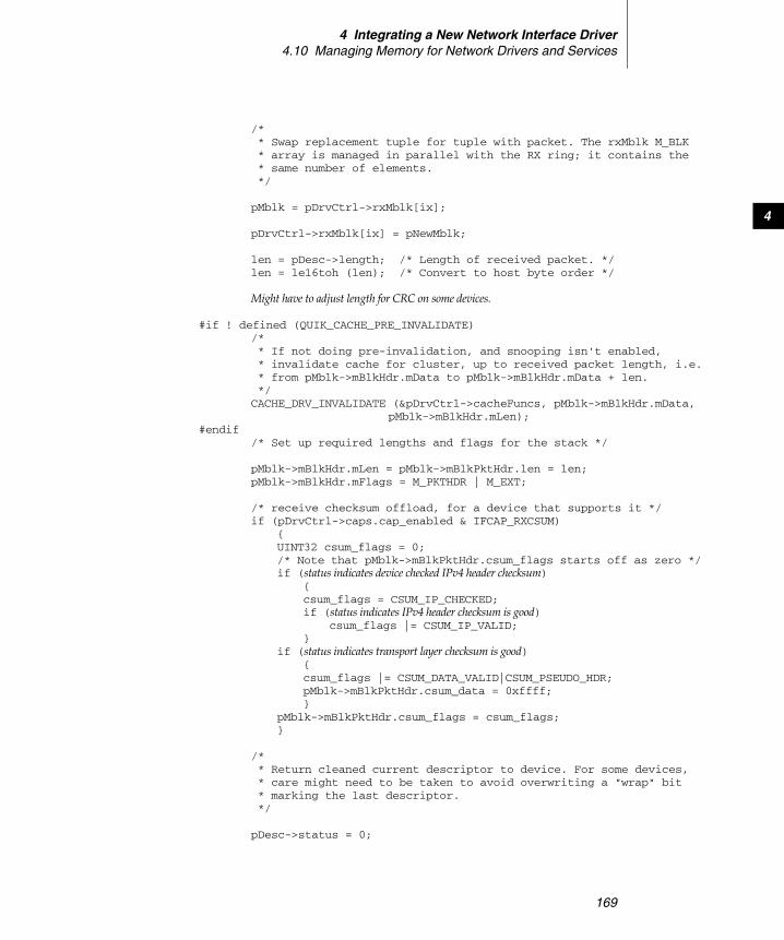
4 Integrating a New Network Interface Driver4.10 Managing Memory for Network Drivers and Services
169
4
/* * Swap replacement tuple for tuple with packet. The rxMblk M_BLK * array is managed in parallel with the RX ring; it contains the * same number of elements. */
pMblk = pDrvCtrl->rxMblk[ix];
pDrvCtrl->rxMblk[ix] = pNewMblk;
len = pDesc->length; /* Length of received packet. */len = le16toh (len); /* Convert to host byte order */
Might have to adjust length for CRC on some devices.
#if ! defined (QUIK_CACHE_PRE_INVALIDATE)/* * If not doing pre-invalidation, and snooping isn't enabled, * invalidate cache for cluster, up to received packet length, i.e. * from pMblk->mBlkHdr.mData to pMblk->mBlkHdr.mData + len. */CACHE_DRV_INVALIDATE (&pDrvCtrl->cacheFuncs, pMblk->mBlkHdr.mData,
pMblk->mBlkHdr.mLen);#endif
/* Set up required lengths and flags for the stack */
pMblk->mBlkHdr.mLen = pMblk->mBlkPktHdr.len = len;pMblk->mBlkHdr.mFlags = M_PKTHDR | M_EXT;
/* receive checksum offload, for a device that supports it */if (pDrvCtrl->caps.cap_enabled & IFCAP_RXCSUM)
{UINT32 csum_flags = 0;/* Note that pMblk->mBlkPktHdr.csum_flags starts off as zero */if (status indicates device checked IPv4 header checksum)
{csum_flags = CSUM_IP_CHECKED;if (status indicates IPv4 header checksum is good)
csum_flags |= CSUM_IP_VALID;}
if (status indicates transport layer checksum is good){csum_flags |= CSUM_DATA_VALID|CSUM_PSEUDO_HDR;pMblk->mBlkPktHdr.csum_data = 0xffff;}
pMblk->mBlkPktHdr.csum_flags = csum_flags;}
/* * Return cleaned current descriptor to device. For some devices, * care might need to be taken to avoid overwriting a "wrap" bit * marking the last descriptor. */
pDesc->status = 0;
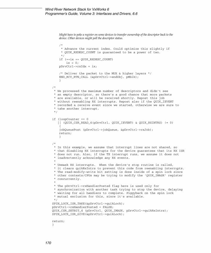
Wind River Network Stack for VxWorks 6Programmer's Guide, Volume 3: Interfaces and Drivers, 6.6
170
Might have to poke a register on some devices to transfer ownership of the descriptor back to thedevice. Other devices might poll the descriptor status.
/* * Advance the current index. Could optimize this slightly if * QUIK_RXDESC_COUNT is guaranteed to be a power of two. */if (++ix == QUIK_RXDESC_COUNT)
ix = 0;pDrvCtrl->rxIdx = ix;
/* Deliver the packet to the MUX & higher layers */END_RCV_RTN_CALL (&pDrvCtrl->endObj, pMblk);}
/* * We processed the maximum number of descriptors and didn't see * an empty descriptor, so there's a good chance that more packets * are available, or will be received shortly. Repost this job * without reenabling RX interrupts. Repost also if the QUIK_IEVENT * recorded a receive event since we started, otherwise we are sure to * take another interrupt. */
if (loopCounter == 0 || (QUIK_CSR_READ_4(pDrvCtrl, QUIK_IEVENT) & QUIK_RXINTRS) != 0)
{jobQueuePost (pDrvCtrl->jobQueue, &pDrvCtrl->rxJob);return;}
/* * In this example, we assume that interrupt lines are not shared, so * that disabling RX interrupts for the device guarantees that its RX ISR * does not run. Also, if the TX interrupt runs, we assume it does not * inadvertently acknowledge any RX events. * * Unmask RX interrupts. When the device's stop routine is called, * it clears quikRxIntrs to prevent this code from reenabling interrupts. * The read-modify-write bit setting is done inside of a spin lock since * other contexts/CPUs may be trying to modify the 'QUIK_IMASK' register * concurrently. ** The pDrvCtrl->rxHandlerPosted flag here is used only for* synchronization with another task trying to stop the device, delaying * waiting for all handlers to complete. Piggyback on the spin lock * mutual exclusion for this, since it's available.*/SPIN_LOCK_ISR_TAKE(&pDrvCtrl->quikLock);pDrvCtrl->rxHandlerPosted = FALSE;QUIK_CSR_SETBIT_4 (pDrvCtrl, QUIK_IMASK, pDrvCtrl->quikRxIntrs);SPIN_LOCK_ISR_GIVE(&pDrvCtrl->quikLock);
return;}
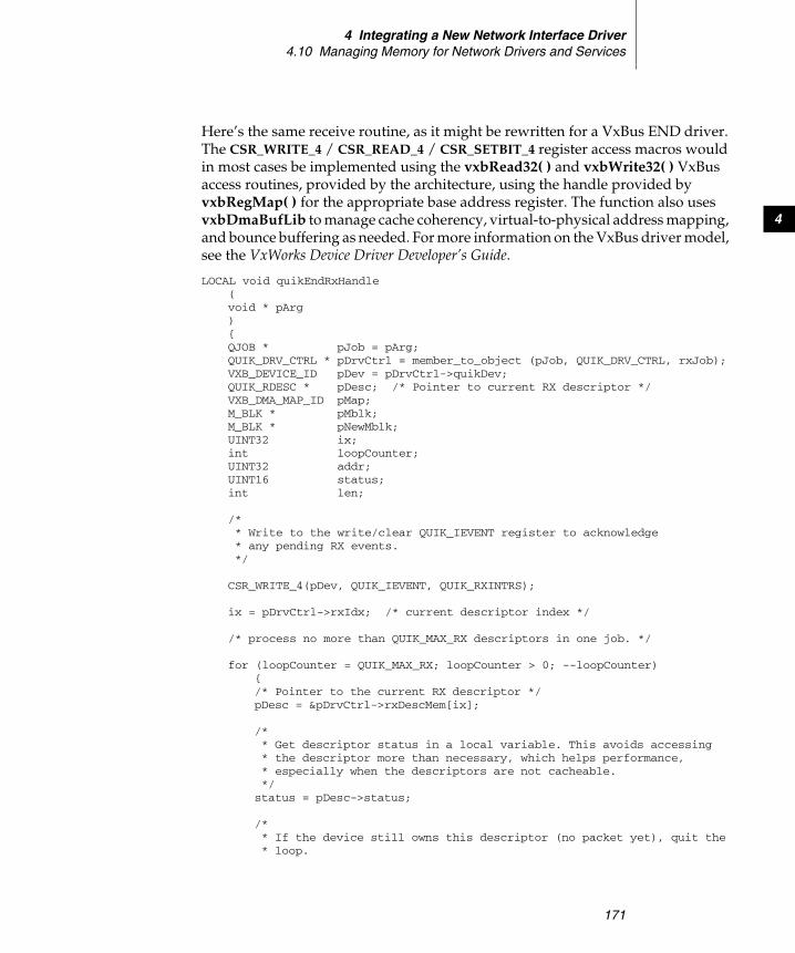
4 Integrating a New Network Interface Driver4.10 Managing Memory for Network Drivers and Services
171
4
Here’s the same receive routine, as it might be rewritten for a VxBus END driver. The CSR_WRITE_4 / CSR_READ_4 / CSR_SETBIT_4 register access macros would in most cases be implemented using the vxbRead32( ) and vxbWrite32( ) VxBus access routines, provided by the architecture, using the handle provided by vxbRegMap( ) for the appropriate base address register. The function also uses vxbDmaBufLib to manage cache coherency, virtual-to-physical address mapping, and bounce buffering as needed. For more information on the VxBus driver model, see the VxWorks Device Driver Developer’s Guide.
LOCAL void quikEndRxHandle(void * pArg){QJOB * pJob = pArg;QUIK_DRV_CTRL * pDrvCtrl = member_to_object (pJob, QUIK_DRV_CTRL, rxJob);VXB_DEVICE_ID pDev = pDrvCtrl->quikDev;QUIK_RDESC * pDesc; /* Pointer to current RX descriptor */VXB_DMA_MAP_ID pMap;M_BLK * pMblk;M_BLK * pNewMblk;UINT32 ix;int loopCounter;UINT32 addr;UINT16 status;int len;
/* * Write to the write/clear QUIK_IEVENT register to acknowledge * any pending RX events. */
CSR_WRITE_4(pDev, QUIK_IEVENT, QUIK_RXINTRS);
ix = pDrvCtrl->rxIdx; /* current descriptor index */
/* process no more than QUIK_MAX_RX descriptors in one job. */
for (loopCounter = QUIK_MAX_RX; loopCounter > 0; --loopCounter){/* Pointer to the current RX descriptor */pDesc = &pDrvCtrl->rxDescMem[ix];
/* * Get descriptor status in a local variable. This avoids accessing * the descriptor more than necessary, which helps performance, * especially when the descriptors are not cacheable. */status = pDesc->status;
/* * If the device still owns this descriptor (no packet yet), quit the * loop.

Wind River Network Stack for VxWorks 6Programmer's Guide, Volume 3: Interfaces and Drivers, 6.6
172
*/if ((status & htole16(QUIK_DESC_DONE)) == 0)
break;
/* * If the descriptor indicates an error, restart reception if the * device requires it, then continue with the next descriptor. */
if ((status & htole16(QUIK_DESC_ERRORS)) != 0){Restart reception if necessary. goto skip;}
/* Allocate a tuple to replace the current one. */
pNewMblk = endPoolTupleGet(pDrvCtrl->endObj.pNetPool);if (pNewMblk == NULL)
{/* * This statistic would be added in when statistics are polled. */pDrvCtrl->stats.inDiscards++; /* maintain software discards *//* * Notify stack that we're out of tuples; perhaps it can free * some. (Might rate-limit this.) */pDrvCtrl->lastError.errCode = END_ERR_NO_BUF;muxError (&pDrvCtrl->endObj, &pDrvCtrl->lastError);
skip:/* * Clean the RX descriptor *pDesc, make it available to the * device again. The address field hasn't changed, and doesn't * need to be rewritten. For some devices, one might have to take * care not to clear a 'wrap' bit marking the last descriptor. */pDesc->status = 0;
Might have to poke a register on some devices to transfer ownership of the descriptor back to thedevice. Other devices might poll the descriptor status.
/* advance the current index */if (++ix == QUIK_RXDESC_COUNT)
ix = 0;pDrvCtrl->rxIdx = ix;continue;}
/* current vxbDmaBufLib map for descriptors current cluster */pMap = pDrvCtrl->rxMblkMap[ix];
/* * Sync the packet buffer and unload the map. * - The first invalidates cache as necessary for the received * packet's buffer. If bounce buffering were required, this

4 Integrating a New Network Interface Driver4.10 Managing Memory for Network Drivers and Services
173
4
* would also do the copy. * - The second releases any bounce buffers or other system * resources needed to map the cluster holding the packet. */
vxbDmaBufSync (pDev, pDrvCtrl->quikMblkTag, pMap, VXB_DMABUFSYNC_PREREAD);
vxbDmaBufMapUnload (pDrvCtrl->quikMblkTag, pMap);
/* * ethernet/optional: Offset in cluster so IP header is 4-byte * aligned. (This is no longer required by the current release of the * Wind River Network Stack, which can handle protocol headers that * are only 2-byte aligned. However, if your device supports DMAing * into buffers that are only two byte aligned, this may help other * software.) */
pNewMblk->mBlkHdr.mData += 2;
/* * Load a DMA map for the replacement cluster. This takes care of * virtual to bus translations, and bounce buffering if required. The * data space lengths in pNewMblk were set by endPoolTupleGet() */
vxbDmaBufMapMblkLoad (pDev, pDrvCtrl->quikMblkTag, pMap, pNewMblk, 0);
/* * Buffer's physical bus address from first entry of fragment array. * Receive buffers are always just a single segment. */pDesc->addr = htole32((UINT32)pMap->fragList[0].frag);
/* * Swap replacement tuple for tuple with packet. The rxMblk M_BLK * array is managed in parallel with the RX ring; it contains the * same number of elements.*/
pMblk = pDrvCtrl->rxMblk[ix];
pDrvCtrl->rxMblk[ix] = pNewMblk;
len = pDesc->length; /* Length of received packet data */len = le16toh (len); /* Convert to host byte order */
Might have to adjust length for CRC on some devices.
/* Set up required lengths and flags for the stack */
pMblk->mBlkHdr.mLen = pMblk->mBlkPktHdr.len = len;pMblk->mBlkHdr.mFlags = M_PKTHDR | M_EXT;

Wind River Network Stack for VxWorks 6Programmer's Guide, Volume 3: Interfaces and Drivers, 6.6
174
/* receive checksum offload, for a device that supports it */if (pDrvCtrl->caps.cap_enabled & IFCAP_RXCSUM)
{UINT32 csum_flags = 0;/* Note that pMblk->mBlkPktHdr.csum_flags starts off as zero */if (status indicates device checked IPv4 header checksum)
{csum_flags = CSUM_IP_CHECKED;if (status indicates IPv4 header checksum is good)
csum_flags |= CSUM_IP_VALID;}
if (status indicates transport layer checksum is good){csum_flags |= CSUM_DATA_VALID|CSUM_PSEUDO_HDR;pMblk->mBlkPktHdr.csum_data = 0xffff;}
pMblk->mBlkPktHdr.csum_flags = csum_flags;}
/* * Return cleaned current descriptor to device. For some devices, * care might have to be taken to avoid overwriting a 'wrap' bit * marking the last descriptor. */
pDesc->status = 0;
Might have to poke a register on some devices to transfer ownership of the descriptor back to the device.Other devices might poll the descriptor status.
/* * Advance the current index. Could optimize this slightly if * QUIK_RXDESC_COUNT is guaranteed to be a power of two. */if (++ix == QUIK_RXDESC_COUNT)
ix = 0;pDrvCtrl->rxIdx = ix;
/* Deliver the packet to the MUX & higher layers */END_RCV_RTN_CALL (&pDrvCtrl->endObj, pMblk);}
/* * We processed the maximum number of descriptors and didn't see an empty * descriptor, so there's a good chance that more packets are available, * or will be received shortly. Repost this job without reenabling RX * interrupts. Repost also if the QUIK_IEVENT recorded a receive event * since we started, otherwise we are sure to take another interrupt. */if (loopCounter == 0
|| (CSR_READ_4(pDev, QUIK_IEVENT) & QUIK_RXINTRS) != 0){jobQueuePost (pDrvCtrl->jobQueue, &pDrvCtrl->rxJob);return;}
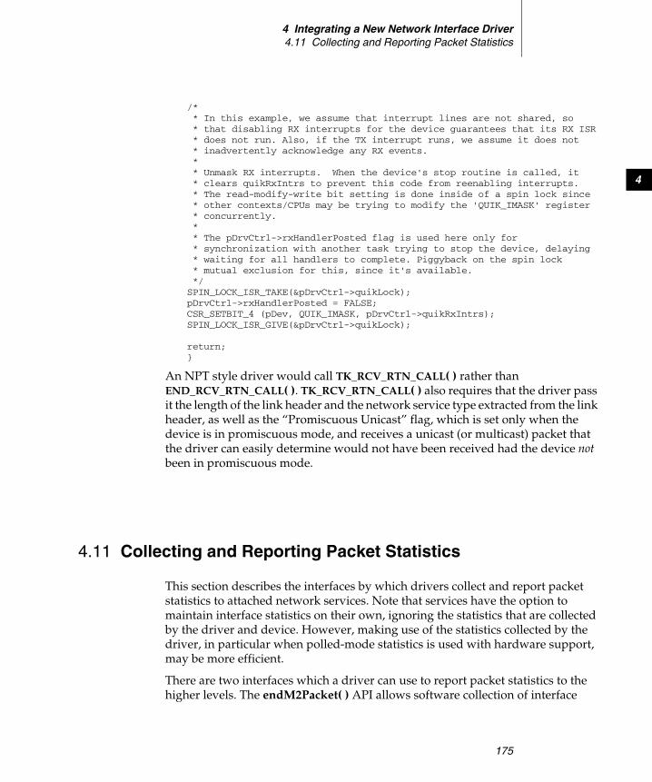
4 Integrating a New Network Interface Driver4.11 Collecting and Reporting Packet Statistics
175
4
/* * In this example, we assume that interrupt lines are not shared, so * that disabling RX interrupts for the device guarantees that its RX ISR * does not run. Also, if the TX interrupt runs, we assume it does not * inadvertently acknowledge any RX events. * * Unmask RX interrupts. When the device's stop routine is called, it * clears quikRxIntrs to prevent this code from reenabling interrupts. * The read-modify-write bit setting is done inside of a spin lock since * other contexts/CPUs may be trying to modify the 'QUIK_IMASK' register * concurrently. * * The pDrvCtrl->rxHandlerPosted flag is used here only for * synchronization with another task trying to stop the device, delaying * waiting for all handlers to complete. Piggyback on the spin lock * mutual exclusion for this, since it's available. */SPIN_LOCK_ISR_TAKE(&pDrvCtrl->quikLock);pDrvCtrl->rxHandlerPosted = FALSE;CSR_SETBIT_4 (pDev, QUIK_IMASK, pDrvCtrl->quikRxIntrs);SPIN_LOCK_ISR_GIVE(&pDrvCtrl->quikLock);
return;}
An NPT style driver would call TK_RCV_RTN_CALL( ) rather than END_RCV_RTN_CALL( ). TK_RCV_RTN_CALL( ) also requires that the driver pass it the length of the link header and the network service type extracted from the link header, as well as the “Promiscuous Unicast” flag, which is set only when the device is in promiscuous mode, and receives a unicast (or multicast) packet that the driver can easily determine would not have been received had the device not been in promiscuous mode.
4.11 Collecting and Reporting Packet Statistics
This section describes the interfaces by which drivers collect and report packet statistics to attached network services. Note that services have the option to maintain interface statistics on their own, ignoring the statistics that are collected by the driver and device. However, making use of the statistics collected by the driver, in particular when polled-mode statistics is used with hardware support, may be more efficient.
There are two interfaces which a driver can use to report packet statistics to the higher levels. The endM2Packet( ) API allows software collection of interface
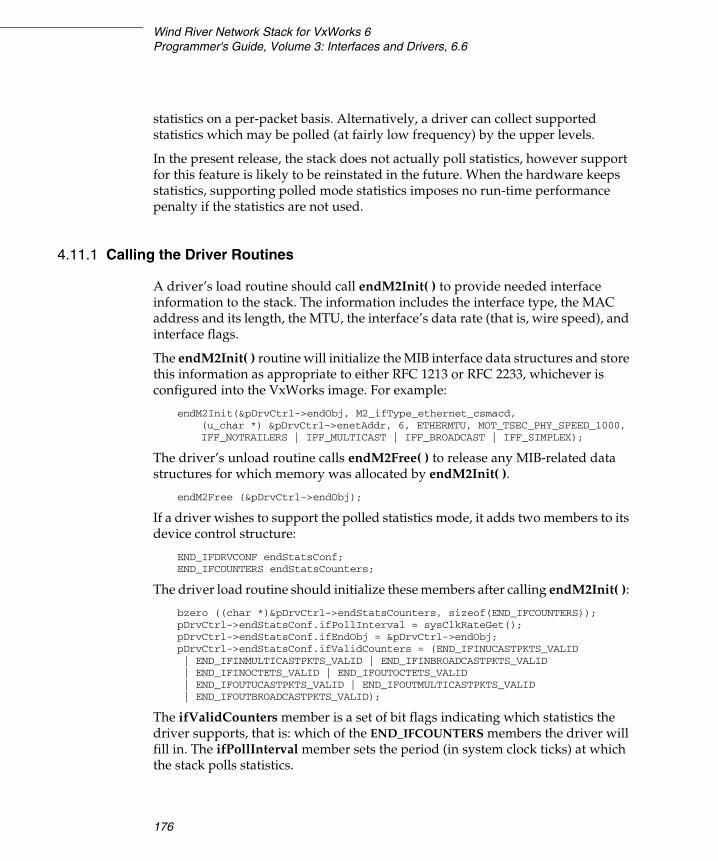
Wind River Network Stack for VxWorks 6Programmer's Guide, Volume 3: Interfaces and Drivers, 6.6
176
statistics on a per-packet basis. Alternatively, a driver can collect supported statistics which may be polled (at fairly low frequency) by the upper levels.
In the present release, the stack does not actually poll statistics, however support for this feature is likely to be reinstated in the future. When the hardware keeps statistics, supporting polled mode statistics imposes no run-time performance penalty if the statistics are not used.
4.11.1 Calling the Driver Routines
A driver’s load routine should call endM2Init( ) to provide needed interface information to the stack. The information includes the interface type, the MAC address and its length, the MTU, the interface’s data rate (that is, wire speed), and interface flags.
The endM2Init( ) routine will initialize the MIB interface data structures and store this information as appropriate to either RFC 1213 or RFC 2233, whichever is configured into the VxWorks image. For example:
endM2Init(&pDrvCtrl->endObj, M2_ifType_ethernet_csmacd, (u_char *) &pDrvCtrl->enetAddr, 6, ETHERMTU, MOT_TSEC_PHY_SPEED_1000, IFF_NOTRAILERS | IFF_MULTICAST | IFF_BROADCAST | IFF_SIMPLEX);
The driver’s unload routine calls endM2Free( ) to release any MIB-related data structures for which memory was allocated by endM2Init( ).
endM2Free (&pDrvCtrl->endObj);
If a driver wishes to support the polled statistics mode, it adds two members to its device control structure:
END_IFDRVCONF endStatsConf; END_IFCOUNTERS endStatsCounters;
The driver load routine should initialize these members after calling endM2Init( ):
bzero ((char *)&pDrvCtrl->endStatsCounters, sizeof(END_IFCOUNTERS)); pDrvCtrl->endStatsConf.ifPollInterval = sysClkRateGet(); pDrvCtrl->endStatsConf.ifEndObj = &pDrvCtrl->endObj; pDrvCtrl->endStatsConf.ifValidCounters = (END_IFINUCASTPKTS_VALID | END_IFINMULTICASTPKTS_VALID | END_IFINBROADCASTPKTS_VALID | END_IFINOCTETS_VALID | END_IFOUTOCTETS_VALID| END_IFOUTUCASTPKTS_VALID | END_IFOUTMULTICASTPKTS_VALID| END_IFOUTBROADCASTPKTS_VALID);
The ifValidCounters member is a set of bit flags indicating which statistics the driver supports, that is: which of the END_IFCOUNTERS members the driver will fill in. The ifPollInterval member sets the period (in system clock ticks) at which the stack polls statistics.
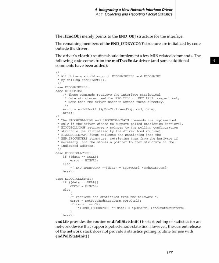
4 Integrating a New Network Interface Driver4.11 Collecting and Reporting Packet Statistics
177
4
The ifEndObj merely points to the END_OBJ structure for the interface.
The remaining members of the END_IFDRVCONF structure are initialized by code outside the driver.
The driver’s xIoctl( ) routine should implement a few MIB-related commands. The following code comes from the motTsecEnd.c driver (and some additional comments have been added):
/* * All drivers should support EIOCGMIB2233 and EIOCGMIB2 * by calling endM2Ioctl(). */ case EIOCGMIB2233: case EIOCGMIB2:
/* These commands retrieve the interface statistical * data structures used for RFC 2233 or RFC 1213, respectively. * Note that the driver doesn't access these directly. */ error = endM2Ioctl (&pDrvCtrl->endObj, cmd, data); break;
/* * The EIOCGPOLLCONF and EIOCGPOLLSTATS commands are implemented * only if the driver wishes to support polled statistics retrieval. * EIOCGPOLLCONF retrieves a pointer to the polling configuration * structure (as initialized by the driver load routine). * EIOCGPOLLSTATS first collects the statistics into the * END_IFCOUNTERS structure, retrieving them from the hardware if * necessary, and the stores a pointer to that structure at the * indicated address. */ case EIOCGPOLLCONF:
if ((data == NULL)) error = EINVAL;
else *((END_IFDRVCONF **)data) = &pDrvCtrl->endStatsConf;
break;
case EIOCGPOLLSTATS: if ((data == NULL))
error = EINVAL; else
{ /* retrieve the statistics from the hardware */ error = motTsecEndStatsDump(pDrvCtrl); if (error == OK)
*((END_IFCOUNTERS **)data) = &pDrvCtrl->endStatsCounters; }
break;
endLib provides the routine endPollStatsInit( ) to start polling of statistics for an network device that supports polled-mode statistics. However, the current release of the network stack does not provide a statistics polling routine for use with endPollStatsInit( ).

Wind River Network Stack for VxWorks 6Programmer's Guide, Volume 3: Interfaces and Drivers, 6.6
178
Polling takes place by calling muxIoctl( ) with the EIOCGPOLLSTATS command for the desired network device. The handler for that command should retrieve from the hardware the supported statistics and store them in the appropriate members of the driver’s END_IFCOUNTERS structure (endStatsCounters in the example above). The counts stored should be the counts accumulated since the last polling call, or (on the first call only) those accumulated since the interface was started.
A driver which does not support the polled mode statistics collection should not implement the EIOCGPOLLCONF and EIOCGPOLLSTATS MUX ioctl commands. Instead, it accumulates statistics per packet by calling the endM2Packet( ) routine, as follows.
For successfully transmitted packets, the driver calls:
endM2Packet(&pDrvCtrl->endObj, pMblk, M2_PACKET_OUT);
For packets which could not be transmitted due to a resource limitation (not for normal TX stalls), the driver should call:
endM2Packet (&pDrvCtrl->endObj, NULL, M2_PACKET_OUT_DISCARD);
For packets which the driver detected a transmission error (not a resource limitation or a normal TX stall), the driver calls:
endM2Packet(&pDrvCtrl->endObj, NULL, M2_PACKET_OUT_ERROR);
For successfully received packets, the driver calls:
endM2Packet(&pDrvCtrl->endObj, pMblk, M2_PACKET_IN);
For packets received with errors, the driver calls:
endM2Packet (&pDrvCtrl->endObj, NULL, M2_PACKET_IN_ERROR);
(In such a case, the driver does not ordinarily deliver the packets to the stack). For packets which could not be received due to resource limits, the driver should call:
endM2Packet (&pDrvCtrl->endObj, NULL, M2_PACKET_IN_DISCARD);
Note that collection of such failure statistics could be a best-effort activity.
179
5Integrating a New
Network Service
5.1 Introduction 179
5.2 Implementing the MUX/Network Service Interface 180
5.3 Interfacing with the MUX 186
5.4 Adding a Socket Interface to Your Service 191
5.1 Introduction
This chapter describes how to integrate a new network service with the Wind River Network Stack. A network service, such as a network protocol, is an implementation of the network and transport layers of the OSI network model.
As shown in Figure 3-1, network services communicate with the data link layer through the MUX interface. Part of porting a new network service to the Wind River Network Stack is porting its data link layer access code to use the MUX interface. Everything specific to the network interface is handled in the drivers of the data link layer, which are described in 4. Integrating a New Network Interface Driver.

Wind River Network Stack for VxWorks 6Programmer's Guide, Volume 3: Interfaces and Drivers, 6.6
180
5.2 Implementing the MUX/Network Service Interface
A network service sends and receives packets through the MUX interface. At minimum, to work with the MUX your service must implement an initialization routine and routines that support packet transfer and error reporting.
5.2.1 Initializing the Interface
Besides loading a network device into the MUX and starting it, you usually want to attach a network stack (that is, a collection of network protocols) to the device. A stack must provide a means to attach itself to a network device. For instance, you can attach the current version of the Wind River IP stack to a network device by calling either of the following functions:
■ ipcom_drv_eth_init (const char * drvname, Ip_u32 drvunit,const char * ifname)
■ ipAttach (int drvunit, char * drvname)
The arguments are in slightly different formats in these functions. ipcom_drv_eth_init( ) is the lowest-level function, and ipAttach( ) is provided for compatibility with previous versions of the Wind River network stack. The drvname and drvunit arguments are the device name and unit number as seen by the MUX and the network driver. If you call ipcom_drv_eth_init( ), you may optionally specify an interface name to be used by the IP stack that differs from the driver-level name. For instance, the following call attaches to the fei2 network interface, but calls it “eth0” at the stack level:
ipcom_drv_eth_init ("fei", 2, "eth0");
NOTE: Well-known service port numbers and other such information are hard coded in ip_net2-6.6/ipcom/port/src/ipcom_getservby.c. There is no API that you can use to add information to this file for the new services that you create, so you must edit this file manually and rebuild your system if you want to add such information.
5 Integrating a New Network Service5.2 Implementing the MUX/Network Service Interface
181
5
On the other hand, the following call attaches the IP stack to the interface, and uses the same interface name “fei2” in the stack as is used at the driver level, which may be less confusing:
ipcom_drv_eth_init ("fei", 2, IP_NULL);
An ipAttach( ) equivalent to this second call would be the following:
ipAttach (2, "fei")
When you call ipcom_drv_eth_init( ) or ipAttach( ) this makes the stack aware of the interface, and causes the stack to bind its protocols to the device. For instance, for an IPv4-capable stack, at least the IPv4 and ARP protocols would be bound to the device, and possibly others.
Whether you write a stack of several protocols or simply a single network service, you need to provide a similar routine that informs your service (or stack) of the network device, and causes it to bind to that device. We will call this routine xAttach( ), imagining that “x” is replaced with your service’s name. You may also wish to modify the startup code to insert calls to xAttach( ) for particular devices. There is no standard interface to accomplish this; however Wind River recommends that you create a component descriptor file (.cdf file) and a configlette so that your service can be handled by the Workbench kernel configurator. (See the VxWorks Kernel Programmer’s Guide for more information.)
Although it is not required, it is a good idea to provide also an xDetach( ) to unbind your service from a network device, and release internal service resources that refer to that device.
The Bind Phase
A network service must bind to a network device before it can send and receive packets through it. A service binds to a network device by calling the mux[Tk]Bind( ) routine (see A.2.20 muxTkBind( ), p.275 and A.2.21 muxBind( ), p.277).
To determine the driver style (END or NPT) of a device that your service wants to bind to, call the muxTkDrvCheck( ) routine (see A.2.23 muxTkDrvCheck( ), p.279). This routine returns 1 (one) for an NPT-style device, 0 (zero) for an END-style device, or -1 (negative one) if no device is found with the specified root name. You need to know the driver style for the following reasons:
■ A network service must bind to an NPT-style device by calling the routine muxTkBind( ) (not muxBind( )).

Wind River Network Stack for VxWorks 6Programmer's Guide, Volume 3: Interfaces and Drivers, 6.6
182
■ A network service may bind to an END-style device using either muxBind( ) or muxTkBind( ); however, using muxTkBind( ) introduces an additional translation layer that may decrease performance a bit.
■ The callback functions that the service provides have different prototypes and somewhat different behavior with muxBind( ) than with muxTkBind( ) (see Figure 4-1).
Almost all Wind River-provided network drivers are END-style drivers rather than NPT-style drivers. A service may choose either to use muxTkBind( ) for all devices (accepting the small performance penalty when binding to an END-style device); or may check the driver style and use muxBind( ) to bind to END-style devices and muxTkBind( ) to bind to NPT-style devices; or may choose to support only one style of driver (END only or NPT only).
The type argument to mux[Tk]Bind( ) is the network service type. The MUX uses the network service type to prioritize the services, and to determine which services see which packets. In addition to the normal network-layer protocol type values from RFC 1700 (corresponding to the Ethernet header type field), there are three special network service type values:
■ A MUX_PROTO_SNARF type service (or “snarf” service) sees all the received packets that are processed by any device to which it is bound, and that are not consumed by an earlier-bound snarf service.
■ A MUX_PROTO_PROMISC type (“promiscuous”) service sees all received packets that are processed by any device to which it is bound, that are not consumed by any snarf, normal, or earlier-bound promiscuous protocol.
■ A MUX_PROTO_OUTPUT type service sees outgoing rather than incoming packets. At most one MUX_PROTO_OUTPUT service may be bound to a network device.
A normal service (or “typed” protocol) sees only packets received by the devices that it is bound to, that match its type, and that were not consumed by any snarf service. At most one typed protocol of a given network service type may be bound to a network device. For any packet received on a device, any snarf services bound to the device see the packet first, then the bound normal service that matches the packet’s service type (if any), then any promiscuous protocol bound to the device; always with the proviso that if an earlier service consumes the packet, it won’t be seen by any later service.
5 Integrating a New Network Service5.2 Implementing the MUX/Network Service Interface
183
5
A service consumes a packet by returning TRUE (or any non-zero value) from its receive routine; it is then responsible for freeing the packet. A service receive routine that does not consume a packet passed to its receive routine returns FALSE and should not modify or free the packet.
A service may bind to more than one network interface; we call the pairing of an network interface with the service bound to it, a “binding instance.” The return value from mux[Tk]Bind( ) is an opaque “cookie” that identifies the binding instance to the MUX. The service subsequently passes this value into various MUX routines that affect a particular network device to which the service is bound, such as muxIoctl( ), and muxTkSend( ).
MUX Interface Routine Database
The MUX maintains a database of three types of “interface routines” that depend upon both the (layer 2) MIB2 interface type and the (layer 3) network service type. The three types of routines are as follows:
■ ADDR_RES_FUNC – a routine for performing address resolution lookups for the network protocol running over the link type (that is, for converting protocol addresses to link addresses)
■ IF_OUTPUT_FUNC – a network-protocol specific routine for outputting packets on interfaces of a specified type
■ MULTI_ADDR_RES_FUNC – a routine for performing multicast address resolution for a network protocol running over specified type of interface.
The database provides routines to dynamically look up (muxIfFuncGet( )), add (muxIfFuncAdd( )), and delete (muxIfFuncDel( )) entries in the database. The function muxIfTypeGet( ) returns the MIB2 interface type code for an network device.
NOTE: Since snarf services process all packets before any typed protocol sees them, the presence of snarf services can decrease the receive performance of all typed protocols bound to the same interface. The WDB agent, when running using the WDB_COMM_END communication type, attaches itself to a network device as a snarf service. When measuring network performance, either do not include the WDB agent, or run performance benchmarks over different interfaces than the one to which the WDB agent is attached (unless you really intend to measure the performance impact of the WDB agent). Some snarf protocols may not need to be permanently attached to an interface. It will help performance to detach any such snarf protocol from an interface when it is not needed, only reattaching it later if it is needed again.

Wind River Network Stack for VxWorks 6Programmer's Guide, Volume 3: Interfaces and Drivers, 6.6
184
The signatures of the function pointers stored in the database is up to the protocol implementation.
Use of the interface routine database is optional. The Wind River IP stack no longer makes use of this facility. However, it is available to service writers as a flexible method to register such service/interface-dependent routines at startup time, and look them up at service bind time.
5.2.2 Using MUX/Service Interface Routines
The subsections that follow provide an overview of how a network service handles the following tasks:
■ sending packets■ device control■ shutting down an interface
Sending Packets
A service sends packets in the form of M_BLK tuple chains over a network interface by calling mux[Tk]Send( ) (see A.2.29 muxTkSend( ), p.284).
Calling mux[Tk]Send( ) normally transfers ownership of the packet M_BLK tuple chain to the network driver; however, if either of these routines returns the value END_ERR_BLOCK, this indicates that the device temporarily lacks transmit queue space to send the packet. In this case the caller keeps ownership of the original packet, and the service may choose to simply drop the packet, or to hold on to it, retransmitting it later in response to a callback by the MUX to its transmit restart routine (see Figure 4-7).
Sending Packets through an END
When sending over an END, it is more efficient for a service to construct the link header itself rather than to allow muxTkSend( ) to construct the link header. This is primarily because if muxTkSend( ) constructs the link header itself and the driver send returns END_ERR_BLOCK, muxTkSend( ) would have to restore a packet to its original state without a link header. Since the packet will either be dropped or queued for resending by the service, this is probably wasted work.
If a service will add the link header to a network-layer datagram, it must first perform any necessary conversion from service addresses to the link-layer addresses appropriate to the END being used. (A service may choose to use the
5 Integrating a New Network Service5.2 Implementing the MUX/Network Service Interface
185
5
MUX interface function database to obtain and cache the function appropriate to do this address resolution.) Knowing the destination and source link-layer addresses and the service’s network service type, the service may call muxAddressForm( ) or muxLinkHeaderCreate( ) to prefix a link header to a packet, making use of the END’s xFormAddress( ) routine (see xFormAddress( ), p.156). Alternatively, if the service knows the type of the END interface being used, and knows the format of the link header for that specific interface type, the service may use its own means to construct a link header; however, the service may not then automatically work with other sorts of devices that provide their own special xFormAddress( ) routines.
Device Control
A driver may respond to specific MUX ioctl commands. Your network service can issue these commands by calling muxIoctl( ) (see A.2.13 muxIoctl( ), p.272 and xIoctl( ), p.136).
Shutting Down an Interface
Relatively few applications need to unload a network device from the MUX, but for those that do, the MUX provides the function muxDevUnload( ). If your application calls muxDevUnload( ), the MUX calls the xStackShutdownRtn( ) routine registered at bind time for each network service still bound to the device (see xStackShutdownRtn( ), p.186).
Within this shutdown routine, the network service must take the necessary steps to close the interface, which include calling muxUnbind( ) to unbind the network service from the device (see A.2.31 muxUnbind( ), p.285). If any of the xStackShutdownRtn( ) calls returns a value other than OK, muxDevUnload( ) immediately returns ERROR. If all of the bound service xStackShutdownRtn( ) calls return OK, muxDevUnload( ) goes on to remove the device from the MUX, and to call the device’s unload routine.
As it may be difficult for some services to accomplish all the work necessary to close and detach from a network interface entirely in the context of the synchronous xStackShutdownRtn( ) call-back, some applications may find it more convenient to start the process of detaching services from a network interface first (using service-specific detach routines), calling muxDevUnload( ) only after all such problematic services have completed unbinding from the interface.

Wind River Network Stack for VxWorks 6Programmer's Guide, Volume 3: Interfaces and Drivers, 6.6
186
5.3 Interfacing with the MUX
When a network service binds to a network driver through the MUX, it must provide references to routines that the MUX can call to handle the following:
■ passing a packet into the service■ passing exceptional event notifications to the service■ restarting transmission by the service through the network device■ shutting down the network service
The prototypes of the routines you specify to handle these routines differ depending on whether you call muxTkBind( ) or muxBind( ) to bind the service to a network interface in the MUX. This chapter describes both interfaces.
5.3.1 Service Routines Registered Using mux[Tk]Bind( )
This section describes the four MUX interface routines that a service implements and references in a mux[Tk]Bind( ) call.
xStackShutdownRtn( )
If your application calls muxDevUnload( ) for a loaded network device, muxDevUnload( ) in turn calls the xStackShutdownRtn( ) of each service that is bound to that device.
Within this routine, the network service must do whatever is necessary to detach the service from the device, which includes releasing any internal references the service has to the device and calling muxUnbind( ) to unbind the service from the device.
muxTkBind( ) Version
For a service bound with muxTkBind( ), the xStackShutdownRtn( ) prototype is:
STATUS xStackShutdownRtn(void * netCallbackId /* the handle/ID installed at bind time */)
! WARNING: In the present implementation, muxDevUnload( ) holds the mutex semaphore guarding the MUX’s list of END-objects when it calls xStartShutdownRtn( ). Protocol shutdown code should take care to avoid misorderings between this mutex and any others used by the service implementation.

5 Integrating a New Network Service5.3 Interfacing with the MUX
187
5
The MUX passes this routine a single argument: the identifier that the service passed into the MUX during the muxTkBind( ) call. This value is opaque to the MUX, but the network service understands it and uses it to identify the particular network interface. It is typically a pointer to the service’s data structure that represents that interface.
muxBind( ) Version
For a service bound with muxBind( ), the xStackShutdownRtn( ) prototype is:
STATUS xStackShutdownRtn(void * pBindCookie, /* binding cookie returned from muxBind() */void * netCallbackId /* the handle/ID installed at bind time */)
The MUX passes this routine two arguments:
1. The binding instance cookie that was returned from muxBind( ).
2. The identifier that the service passed into the MUX during the muxBind( ) call. This value is opaque to the MUX, but the network service understands it and uses it to identify the particular END interface. It is typically a pointer to the service’s data structure that represents that interface.
xStackRcvRtn( )
The MUX delivers packets it receives from the network device to a service by calling the xStackRcvRtn( ) callback that the service registered when it called mux[Tk]Bind( ). The xStackRcvRtn( ) is called only in the context of the network job queue used by the network interface.
The netCallbackId parameter that the MUX passes into xStackRcvRtn( ) is the one the service specified at bind-time. The type parameter specifies the network service type of the packet. The pPkt parameter points to the lead M_BLK in the tuple chain that describes the packet.
If a network service accepts the packet by returning TRUE, it takes ownership of the packet and is responsible for freeing the given M_BLK chain when the service is finished with it. If it returns FALSE it should neither free nor modify the packet.

Wind River Network Stack for VxWorks 6Programmer's Guide, Volume 3: Interfaces and Drivers, 6.6
188
muxTkBind( ) Version
For a service bound with muxTkBind( ) the xStackRcvRtn( ) prototype is:
BOOL xStackRcvRtn(void * netCallbackId, /* the handle/ID installed at bind time */long type, /* network service type of the packet */M_BLK_ID pPkt, /* the packet as an M_BLK tuple chain*/void * pSpareData /* pointer to optional data from driver */)
In this version of xStackRcvRtn( ), pSpareData is either NULL (if the binding was to an END) or is the pSpareData value that was passed as the last argument to muxTkReceive( ) by the NPT driver’s receive handler (if the binding was to an NPT device). Note that even for an NPT-style device, there are no conventions established for the use of pSpareData; the network service and the network driver have to know about each other and share a common interpretation of this value, for it to be of any use.
For services bound with muxTkBind( ), with the exception of MUX_PROTO_OUTPUT services bound to NPT-style devices, the link header is always present in the cluster in the first tuple of the chain describing the packet, but the lead M_BLK may be adjusted to skip over the link header:
■ For normal typed protocols, pPkt->mBlkHdr.mData is advanced by the size of the link header, while pPkt->mBlkHdr.mLen and pPkt->mBlkPktHdr.len are decreased by the size of the link header.
■ For MUX_PROTO_SNARF and MUX_PROTO_PROMISC services, the lead M_BLK is not adjusted, that is pPkt->mBlkHdr.mData still points to the start of the link header, and pPkt->mBlkHdr.mLen and pPkt->mBlkPktHdr.len still include the length of the link header.
■ For MUX_PROTO_OUTPUT services bound to ENDs, pPkt->mBlkHdr.mData is advanced by the size of the link header, while pPkt->mBlkHdr.mLen and pPkt->mBlkPktHdr.len are decreased by the size of the link header. A pointer to the destination MAC address in the header is placed in pPkt->mBlkPktHdr.rcvif.
– For MUX_PROTO_OUTPUT services bound to NPT devices, there may be no link header in the packet (passed to muxTkSend( )). The destination MAC address pointer passed to muxTkSend( ) is placed in pPkt->mBlkPktHdr.rcvif before the output service’s xStackRcvRtn( ) function is called. The pPkt M_BLK is not adjusted from that passed to muxTkSend( ).

5 Integrating a New Network Service5.3 Interfacing with the MUX
189
5
■ The size of the link header (the network service offset) is stored in pPkt->mBlkHdr.offset1.
muxBind( ) Version
For a service bound with muxBind( ) the xStackRcvRtn( ) prototype is:
BOOL xStackRcvRtn(void * pBindCookie, /* returned by muxBind() */long type, /* the network service type of the packet*/M_BLK_ID pPkt, /* the packet as an M_BLK tuple chain */LL_HDR_INFO * pLLHInfo, /* link-level header info structure */void * pCallbackId /* the handle/ID installed at bind time */)
In this version of xStackRcvRtn( ), pBindCookie is the binding cookie that is returned by muxBind( ). As this value is opaque to the service, it is probably less useful than the netCallbackId value passed into the other version of xStackRcvRtn( ).
For all services bound with muxBind( ), the link-level header is present at the start of the packet, and is described in the LL_HDR_INFO structure pointed to by the pLLHInfo argument (see A.3.11 LL_HDR_INFO, p.302). The MUX calls the END device’s xPacketDataGet( ) routine to parse the link header and fill out this structure. The most important information in this structure is the size of the link header, but it also holds the offsets and sizes of the source and destination link-level addresses, as well as (redundantly) the network service type of the packet.
xStackErrorRtn( )
A device notifies the MUX of various exceptional events it encounters by calling muxError( ), and the MUX forwards these to the network services that are bound to the device by calling xStackErrorRtn( ). It is up to the network service to take any necessary action when it receives the event notification.
The MUX passes this routine a pointer to an END_ERR structure and the netCallbackId value that was passed at bind time. See A.3.5 END_ERR, p.293, for more information on the various events that may be reported in this way.
Wind River Network Stack for VxWorks 6Programmer's Guide, Volume 3: Interfaces and Drivers, 6.6
190
muxTkBind( ) Version
For a service bound with muxTkBind( ) the xStackErrorRtn( ) prototype is:
void xStackErrorRtn(void * netCallbackId, /* the handle/ID installed at bind time */END_ERR * pError /* pointer to structure containing error */)
muxBind( ) Version
For a service bound with muxBind( ) the xStackErrorRtn( ) prototype is:
void xStackErrorRtn(void * pEND, /* END_OBJ passed to the MUX by the driver */END_ERR * pError, /* pointer to structure containing error */void * netCallbackId /* the handle/ID installed at bind time */)
This version of the xStackErrorRtn( ) routine takes an additional argument, pEnd, which describes the END device.
xStackRestartRtn( )
The MUX calls this routine to restart transmission over a network device by any network services bound to the device that care to do so.
When an device’s xSend( ) routine returns END_ERR_BLOCK, it is indicating that it cannot schedule the packet for transmission immediately (usually due to a temporary lack of space in the transmit ring). The sending service may choose to drop the packet, or to hold on to it for later retransmission. Having returned END_ERR_BLOCK, the driver guarantees that it will call muxTxRestart( ) when the device is again ready to accept packets for transmission. muxTxRestart( ) calls the xStackRestartRtn( ) routine for each service that is bound to the device and that provided such a routine. The xStackRestartRtn( ) routine may respond by sending any packets that it has queued for the device, until it sends them all or the send routine returns END_ERR_BLOCK once more.
The MUX passes this routine the netCallbackId value that the service passed to mux[Tk]Bind( ).

5 Integrating a New Network Service5.4 Adding a Socket Interface to Your Service
191
5
muxTkBind( ) Version
For a service bound with muxTkBind( ) the xStackRestartRtn( ) prototype is:
STATUS xStackRestartRtn(void * netCallbackId /* the handle/ID installed at bind time */)
muxBind( ) Version
For a service bound with muxBind( ) the xStackRestartRtn( ) prototype is:
STATUS xStackRestartRtn(void * pEND, /* END_OBJ passed to the MUX by the driver */void * netCallbackId /* the handle/ID installed at bind time */)
This version of the xStackRestartRtn( ) routine takes an additional argument, pEnd, which describes the END device.
5.4 Adding a Socket Interface to Your Service
One way to allow applications to access your network service is to add sockets support to the service. In order to make it easier for you to write a network service that includes sockets support, the Wind River Network Stack includes a standard sockets interface.
With the standard socket interface, you can add new socket back ends to access your network service, and through it, the network. This allows developers who are already familiar with the standard sockets API to more easily use your service.
With the standard sockets interface, an application can create and use sockets of different address families, which may be managed by different back end service implementations. A layered architecture makes this possible. The Wind River standard sockets interface, implemented by sockLib, is a layer above your back end socket layer, as shown in Figure 5-1.
This section shows you how to implement a sockets back end.
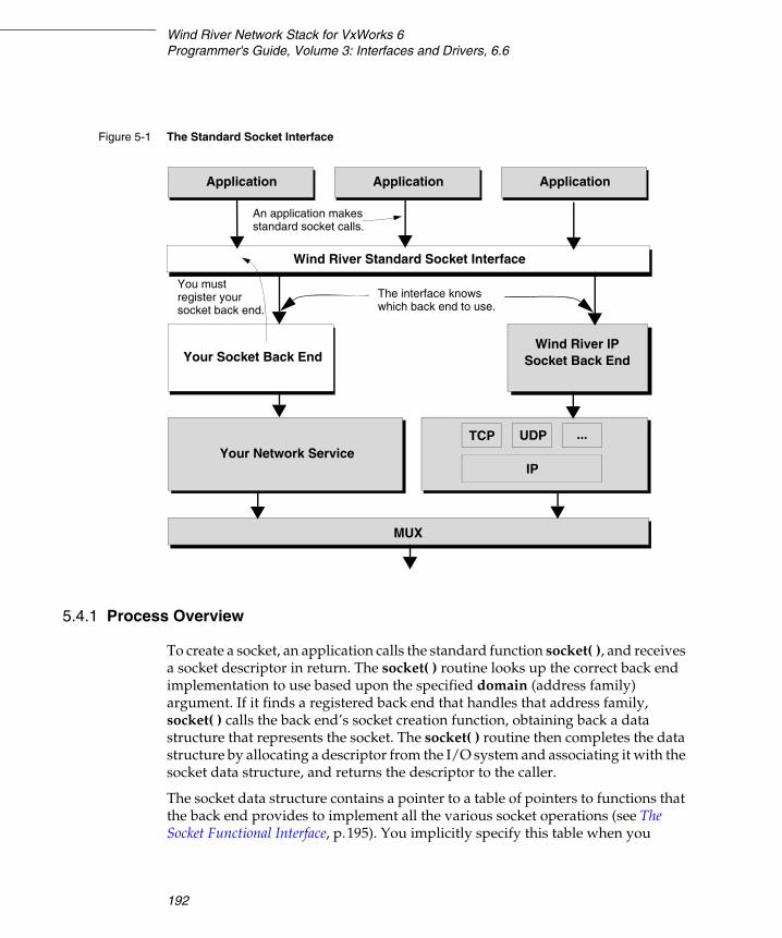
Wind River Network Stack for VxWorks 6Programmer's Guide, Volume 3: Interfaces and Drivers, 6.6
192
5.4.1 Process Overview
To create a socket, an application calls the standard function socket( ), and receives a socket descriptor in return. The socket( ) routine looks up the correct back end implementation to use based upon the specified domain (address family) argument. If it finds a registered back end that handles that address family, socket( ) calls the back end’s socket creation function, obtaining back a data structure that represents the socket. The socket( ) routine then completes the data structure by allocating a descriptor from the I/O system and associating it with the socket data structure, and returns the descriptor to the caller.
The socket data structure contains a pointer to a table of pointers to functions that the back end provides to implement all the various socket operations (see The Socket Functional Interface, p.195). You implicitly specify this table when you
Figure 5-1 The Standard Socket Interface
Your Socket Back End
Wind River Standard Socket Interface
Application
MUX
TCP
IP
ApplicationApplication
UDP ...Your Network Service
Wind River IPSocket Back End
The interface knows which back end to use.
You must register your socket back end.
An application makes standard socket calls.

5 Integrating a New Network Service5.4 Adding a Socket Interface to Your Service
193
5
register the socket back end by calling sockLibAdd( ), as discussed in 5.4.2 Registering a Socket Back End, p.193. When an application makes sockets API calls other than socket( ), the socket descriptor returned by socket( ) is one of the arguments. The sockLib implementation for each such sockets API call converts the socket descriptor to the underlying socket data structure using I/O system descriptor look-up facilities, fetches the pointer to the back end’s function table, and calls the appropriate back-end function to complete the call.
The I/O system functions read( ), write( ), ioctl( ), and close( ) may also be used on socket descriptors. In this case, the I/O system converts the descriptor to the underlying socket data structure, calls the registered sockLib read, write, ioctl, or close function, which in turn calls the back end’s read, write, ioctl, or close handler via the back end function table. sockLib registers a single I/O system driver to handle all socket descriptors.
5.4.2 Registering a Socket Back End
You can register a socket back end implementation by calling sockLibAdd( ) some time during system start-up after sockLib is itself initialized by a call to sockLibInit( ).
! WARNING: In the present release, the socket data structure used by sockLib is in fact a struct socket, declared in target/h/wrn/coreip/net/socketvar.h. This is primarily for historical reasons. The struct socket structure contains many members, only a few of which are needed by sockLib itself; and some socket back ends will prefer not to use the other members of struct socket. It is very likely that a future release will replace (or modify) struct socket with a much smaller structure (which would be embeddable in a back end’s private data structure representing a socket). The following members from struct socket are likely to remain in the new, smaller structure:
struct sockFunc * pSockFuncTbl; /* socket back-end function table */int so_fd; /* the socket file descriptor */void * so_bkendaux; /* socket back-end auxiliary data */
If your back end uses other members of struct socket, then after the change to the smaller structure, you may have to move these members to your back end’s own private socket data structure.
Generally, the interface between sockLib and socket back ends, as well as the interface for registering socket back ends, although described here as it presently exists, should be considered somewhat fluid. Wind River may modify these interfaces as it sees fit in future releases.
Wind River Network Stack for VxWorks 6Programmer's Guide, Volume 3: Interfaces and Drivers, 6.6
194
The sockLibAdd( ) routine has the following prototype:
STATUS sockLibAdd(FUNCPTR sockLibInitRtn, /* back end's initialization routine */int domainMap, /* unused */int domainReal, /* address family */)
The routine returns OK, or ERROR if the routine could not add the socket back end. The routine takes three parameters:
sockLibInitRtn A pointer to your xSockLibInit( ) routine that sockLibAdd( ) invokes. sockLibAdd( ) calls this routine as if it had the following prototype:
SOCK_FUNC * xSockLibInit (void);
That is, it is passed no arguments, and it is expected to return a pointer to an initialized SOCK_FUNC structure, which is the table of function pointers for the back end (see The Socket Functional Interface, p.195).
domainMap sockLibAdd( ) ignores this parameter.
domainReal This parameter specifies the address family that this back end implements. A back end may support more than one address family, but in such a case you must call sockLibAdd( ) multiple times, once per address family. Allowed address families are in the range from 1 to AF_MAX-1, and the AF_ constants that identify these address families (AF_INET, and so forth) are declared in target/h/wrn/coreip/sys/socket.h.
At most one back end will handle sockets of any given address family. For example, the native Wind River Network Stack normally handles sockets of the AF_INET, AF_INET6, AF_ROUTE, and AF_PACKET families. A socket back end of your own implementation may not handle one of these address families without disabling handling of that family by the native stack.

5 Integrating a New Network Service5.4 Adding a Socket Interface to Your Service
195
5
The Socket Functional Interface
The socket functional interface is the set of implementations of standard socket routines that a particular socket back end supports. SOCK_FUNC is declared in target/h/wrn/coreip/sockFunc.h as follows:
typedef struct sockFunc /* SOCK_FUNC */{FUNCPTR libInitRtn; /* unused */FUNCPTR acceptRtn; /* accept() */FUNCPTR bindRtn; /* bind() */FUNCPTR connectRtn; /* connect() */FUNCPTR connectWithTimeoutRtn; /* connectWithTimeout() */FUNCPTR getpeernameRtn; /* getpeername() */FUNCPTR getsocknameRtn; /* getsockname() */FUNCPTR listenRtn; /* listen() */FUNCPTR recvRtn; /* recv() */FUNCPTR recvfromRtn; /* recvfrom() */FUNCPTR recvmsgRtn; /* recvmsg() */FUNCPTR sendRtn; /* send() */FUNCPTR sendtoRtn; /* sendto() */FUNCPTR sendmsgRtn; /* sendmsg() */FUNCPTR shutdownRtn; /* shutdown() */FUNCPTR socketRtn; /* socket() */FUNCPTR getsockoptRtn; /* getsockopt() */FUNCPTR setsockoptRtn; /* setsockopt() */FUNCPTR zbufRtn; /* not supported */
/* The following IO-system handlers are called via wrappers *//* in sockLib.c. */
FUNCPTR closeRtn; /* close() */FUNCPTR readRtn; /* read() */FUNCPTR writeRtn; /* write() */FUNCPTR ioctlRtn; /* ioctl() */} SOCK_FUNC;
The use of the FUNCPTR type is unfortunate, as it provides neither type checking, nor any guide to those who implement back-ends of the arguments passed to the functions, nor the return values expected of them. With few exceptions, you can get the pseudo-prototype for one of these routines, which indicates how it is actually called, by considering the corresponding standard sockets API function prototype in sockLib.h, or the corresponding I/O system function prototype in ioLib.h (replacing the integer socket descriptor argument with a struct socket * argument). For instance, the connect API is prototyped in sockLib.h as the following:
extern STATUS connect (int s, struct sockaddr * name, int namelen);
So, the back end function called through the connectRtn function pointer is called as if it had the following prototype:

Wind River Network Stack for VxWorks 6Programmer's Guide, Volume 3: Interfaces and Drivers, 6.6
196
STATUS xConnectRtn (struct socket * so, struct sockaddr * name,int namelen);
sockLib’s connect( ) implementation converts the integer socket descriptor passed as its first argument s, to the struct socket pointer so, and calls the back end’s xConnectRtn( ) routine, replacing s with so and passing the name and namelen arguments unchanged. From the so argument, the socket back end can find its own private data for the socket; the so_bkendaux member of struct socket is intended as a pointer to such private data. (Alternatively, since the back end’s socketRtn( ) is responsible for allocating the struct socket, the back end may choose to embed the struct socket in a larger structure containing also the private data.)
The return value from the back end xConnectRtn( ) is same as the return value from connect( ).
Consult the sockLib reference pages for additional information on the intended behavior of the sockets API functions. External sockets API information is also very useful; for instance IEEE Std 1003.1 contains the official Posix descriptions of sockets API functions and data structures. (For various historical reasons, the VxWorks sockets API prototypes do not always match exactly those defined by IEEE 1003.1.) For general background on sockets programming, see W. Richard Stevens, Unix Network Programming - Networking APIs: Sockets and XTI, Volume 1.
There are exceptions to the above rule-of-thumb. These are socketRtn, acceptRtn, and ioctlRtn:
xSocketRtn( )
The xSocketRtn( ) routine has the following prototype:
int xSocketRtn(int domain, /* socket domain or address family number */int type, /* socket's nature, e.g. SOCK_DGRAM */int protocol, /* the protocol variety of the socket */struct socket ** ppSo /* the socket structure */)
The back end’s xSocketRtn( ) is responsible for allocating and initializing a struct socket and any other structures that the back end needs to represent a socket of the specified domain, type, and protocol (these are passed directly from the corresponding arguments to the socket( ) routine). The allocation may be done using the kernel heap, a netBufLib pool, or a back-end specific method. If the xSocketRtn( ) cannot allocate and initialize a socket of the specified kind, xSocketRtn( ) must free any partial allocations, set errno to the appropriate value (such as ENOMEM, ENOBUFS, EAFNOSUPPORT, EPROTONOSUPPORT, EPROTOTYPE), and return ERROR.

5 Integrating a New Network Service5.4 Adding a Socket Interface to Your Service
197
5
Otherwise, xSocketRtn( ) stores a pointer to the allocated struct socket at the address specified by ppSo, and returns OK. The socket( ) code will then itself store a pointer to the back end’s SOCK_FUNC table in the returned struct socket’s pSockFuncTbl member, then attempt to allocate a file descriptor from the I/O system, associating it with the socket. The socket( ) call may still fail if the calling RTP (possibly the kernel) is out of file descriptors. In this case, the socket( ) code will immediately call the back end’s xCloseRtn( ) function, to destroy the socket, and return ERROR. On the other hand, if a file descriptor is successfully allocated, the socket( ) code stores that file descriptor in the so_fd member, and return the file descriptor as its result.
sockLib( ) itself has no requirements as to how the back end initializes the struct socket structure that it allocates; however, the back end will probably want to initialize any members (other than pSockFuncTbl and so_fd) that it needs, in particular setting so_bkendaux to point to any auxiliary private data the back end wishes to maintain for the socket.
xAcceptRtn( )
The xAcceptRtn( ) routine has the following prototype:
STATUS xAcceptRtn(struct socket ** ppSo, /* IN: parent socket. OUT: child socket. */struct sockaddr * addr, /* Address of child's peer. */int * addrlen /* Length of child's peer's address. */);
The back end’s xAcceptRtn( ) is called by the accept( ) code in sockLib. This accept( ) code does some checking, however, before it calls xAcceptRtn( ). If addr is non-NULL but addrlen is NULL, accept( ) returns an error. Otherwise, accept( ) attempts to convert the descriptor passed as its first argument to a struct socket. If the descriptor is not a valid socket descriptor, accept( ) again returns an error. If the back end does not provide any accept handler, that is, if the acceptRtn member of the back end’s SOCK_FUNC structure is NULL, accept( ) again returns ERROR.
Otherwise, the accept( ) code calls the back end’s xAcceptRtn( ) function, passing as the first argument the address of a pointer to the struct socket, converted from the socket descriptor passed to accept( ). The other two arguments to xAcceptRtn( ) are passed directly from the corresponding arguments of accept( ).
The back end’s xAcceptRtn( ) must check that the socket passed in by the first argument is in fact a listening parent socket, capable of providing child socket connections to accept( ). If not, xAcceptRtn( ) must return ERROR and set errno appropriately (see IEEE Std 1003.1). If the parent can provide child connections,

Wind River Network Stack for VxWorks 6Programmer's Guide, Volume 3: Interfaces and Drivers, 6.6
198
but no completed child socket connection is presently queued for the parent, then xAcceptRtn( ) must do one of the following:
■ set errno to EAGAIN or EWOULDBLOCK and return ERROR, if the parent socket is non-blocking; or
■ if the parent socket is blocking, pend until either a completed child socket connection becomes available (or optionally: until a timeout, signal, or other implementation defined event occurs, in which case errno should be set appropriately, and ERROR returned).
If a completed child socket connection becomes available, xAcceptRtn( ) allocates a struct socket for it (and any other needed private data structures), and stores a pointer to the child struct socket at the address passed in the ppSo argument, overwriting the previous pointer to the parent’s struct socket. If the addr argument is non-NULL, xAcceptRtn( ) obtains the child’s peer’s socket address, and copies it (truncating to the length specified in the int pointed to by addrlen, if necessary) to the specified address addr; and finally storing the actual address length in the integer pointed to by addrlen. xAcceptRtn( ) then returns OK.
If xAcceptRtn( ) does not return ERROR, the accept( ) code stores a pointer to the back end’s SOCK_FUNC table in the child socket’s pSockFuncTbl member, then goes on to attempt to allocate a socket descriptor from the I/O system for the child socket. If this fails, accept( ) immediately calls the back end’s xCloseRtn( ) routine and returns ERROR.
Otherwise, accept( ) stores the allocated socket descriptor in the child struct socket’s so_fd member, and returns that socket descriptor as its result.
xIoctlRtn( )
The xIoctlRtn( ) routine has the following prototype:
int xIoctlRtn(struct socket * so, /* the socket */u_long cmd, /* ioctl command code */void * data /* ioctl argument */void * mode /* indicates if the call is from user space */)
The back end’s xIoctlRtn( ) routine is called when the I/O system processes an ioctl( ) call made on a socket descriptor. The routine is called as the rule of thumb would suggest, passing the struct socket pointer so instead of a socket file descriptor and passing the ioctl command and data arguments unchanged, except that xIoctlRtn( ) is also passed another argument mode. This argument is NULL if ioctl( ) was called from the kernel; it is an arbitrary non-NULL value if ioctl( ) was

5 Integrating a New Network Service5.4 Adding a Socket Interface to Your Service
199
5
called from a user-space RTP. This indication is intended to help support validation of user-space ioctl arguments.
5.4.3 Memory Validation and Socket Ioctls
Socket APIs are expected to validate their arguments for proper memory access when called from a user-space RTP application. This is accomplished for most socket calls in the socketScLib shim library. This contains the system call handlers for sockets API system calls; these handlers execute in the kernel and perform argument memory access validation before calling the appropriate kernel socket APIs in sockLib. (Memory validation is done using the scMemValidate( ) routine; see its reference entry for more information.)
Memory validation for the read( ) and write( ) buffer and length arguments is done by the I/O system’s system call handler code. However, ioctl( ) calls made on socket descriptors are a special case. The I/O system level does not have knowledge about the form and use of the ioctl arguments passed to ioctl operations implemented by the lower-level “driver” code, such as the socket back ends, and so cannot do the memory validation. In VxWorks, the lower-level drivers (including socket back ends) are expected to do memory validation for the ioctls they implement which may be called by RTP applications.
sockScLib provides a pair of functions that can aid a socket back end in doing ioctl argument memory validation. These functions should only be called through the following function pointers:
int (*pSockIoctlMemVal) ( unsigned int cmd, void * data );
STATUS (*pUnixIoctlMemVal) ( unsigned int cmd, const void * pData );
The function pointers are only non-NULL when RTP support is included in the VxWorks image. They should only be called when the mode argument passed to xIoctlRtn( ) is non-NULL, indicating an ioctl( ) call from user space.
Most (although unfortunately not all) ioctl commands on sockets encode the length and usage of the command argument in the ioctl command code itself. Ioctl codes following the conventions in target/h/sys/ioctl.h or target/h/wrn/coreip/ipnet/ipioctl.h encode whether the ioctl argument is a pointer
Wind River Network Stack for VxWorks 6Programmer's Guide, Volume 3: Interfaces and Drivers, 6.6
200
to a buffer that is read into the kernel, written to by the kernel, or both; and if so, how large the buffer is. The top-level memory validation for such ioctl codes may be performed by calling pUnixIoctlMemVal( ), passing it the command code and the ioctl data argument. This routine returns OK if memory validation succeeds, otherwise it sets errno appropriately and returns ERROR.
There are some limitations of the function referenced by pUnixIoctlMemVal:
■ It does not check that the ioctl code is supported by the back end.
■ It assumes without any check that the code follows the conventions encoding the parameter length and usage, as described in target/h/sys/ioctl.h.
■ It only does top-level checking: if the ioctl parameter is a pointer to a buffer holding a data structure that contains additional pointers, these other pointers are not validated. Validating them is the responsibility of the back end.
The pSockIoctlMemVal( ) function pointer behaves similarly to pUnixIoctlMemVal( ), except that it additionally validates memory for a small number of ioctl( ) codes that do not follow the conventions upon which pUnixIoctlMemVal( ) depends. In the present release, these additional ioctl codes are FIONBIO, FIONREAD, FIOSELECT, and FIOUNSELECT. It also supports SIOCMUXPASSTHRU and SIOCMUXL2PASSTHRU, doing second-level validation of the embedded MUX ioctl commands in these two ioctls’ arguments. For any other ioctl code passed to pSockIoctlMemVal( ), it simply calls pUnixIoctlMemVal( ).
201
6Working with the
802.1Q VLAN Tag
6.1 Introduction 201
6.2 Adding VLAN Support 202
6.3 About the 802.1Q VLAN Tag Header 203
6.4 MUX Extensions for Layer 2 VLAN Support 204
6.5 Current MUX-L2 Limitations 211
6.6 VLAN Management 211
6.7 Using the MUX-L2 Show Routines 219
6.1 Introduction
This chapter shows you how to work with 802.1Q VLAN tagging in the Wind River Network Stack. It assumes that you are familiar with the principles and operations of IEEE 802.1Q VLAN.
VLAN tagging is part of the network stack. You can access it by any of the following methods:
NOTE: 802.1Q VLAN tagging is available in the Wind River Platforms builds of the network stack. The Wind River General Purpose Platform, VxWorks Edition, does not include 802.1Q VLAN tagging.
Wind River Network Stack for VxWorks 6Programmer's Guide, Volume 3: Interfaces and Drivers, 6.6
202
■ muxL2...( ) routines (if you have built the stack with MUX-L2 support)■ extensions to the socket interface■ a pseudo-interface with which you can manage the VLAN as a subnet
6.2 Adding VLAN Support
Include the INCLUDE_IPNET_USE_VLAN (VLAN Pseudo Interface support) component in your build if you want it to include Layer 2 subnet-based VLANs. If you include this component, this initializes the FreeBSD-style VLAN pseudo-interface for subnet-based VLAN support.
MUX Layer 2 Support
The INCLUDE_MUX_L2 (MUX Layer 2 support) component pulls in the MUX network interface library for layer 2. Including this component initializes the MUX-L2 infrastructure for VLAN support.
To allow the network stack to interoperate with MUX-L2, you must rebuild it with the IPCOM_VXWORKS_USE_MUX_L2 flag by using one of the following methods:
■ Enable the IPCOM_VXWORKS_USE_MUX_L2 #define found in ipcom/port/vxworks/config/ipcom_pconfig.h
■ Build with the flag ADDED_CFLAGS+=-DIPCOM_VXWORKS_USE_MUX_L2
The INCLUDE_MUX_L2 component requires the following components:
■ INCLUDE_END (END interface support) ■ INCLUDE_ETHERNET (Ethernet multicast library support)
The INCLUDE_MUX_L2 component contains the following configuration parameters:
MUX_L2_MAX_VLANS_CFG (Maximum number of 802.1Q VLANs supports)the maximum number of 802.1Q VLANs supported on the target (default = 16)
MUX_L2_NUM_PORTS_CFG (Number of ports that the device has)the maximum number of physical ports available to the target (default = 16)

6 Working with the 802.1Q VLAN Tag6.3 About the 802.1Q VLAN Tag Header
203
6
L2Config
The INCLUDE_L2CONFIG (l2config) component provides support for the layer 2 configuration utility. If you include this component, this initializes the L2 command-line configuration utility. This component requires the INCLUDE_MUX_L2 component.
6.3 About the 802.1Q VLAN Tag Header
The Wind River VLAN implementation supports the following three frame types:
■ Untagged frames – frames that do not carry any identification of the VLAN to which they belong
■ Priority-tagged frames – frames that include a tag header carrying explicit user priority information but not identifying the frames as belonging to a specific VLAN
■ VLAN-tagged frames – frames that include an explicit identification of the VLAN to which they belong
The VLAN tag header is as shown in Figure 6-1.
The 802.1Q tag is a four-byte field after the six-byte Source Address field and before the two-byte length/type field in the Ethernet header. An 802.1Q VLAN tagging implementation indicates that a frame is tagged by setting its Type field to the VLAN Identifier Protocol (0x8100). This means the next two bytes contain Tag Control Information.

Wind River Network Stack for VxWorks 6Programmer's Guide, Volume 3: Interfaces and Drivers, 6.6
204
The two-byte Tag Control Information consists of a 3-bit priority (0-7) value, a Canonical Format Indicator (CFI) field (0 for Ethernet), and a 12-bit VLAN Identifier (VID). The 12-bit VID field can take any value from 0 to 4095, but two of these values have special meanings according to the 802.1Q specification: The value of all ones (0xFFF) is reserved but currently unused; the value of all zeros (0x000) indicates a that the frame is priority-tagged and that no VID is present in the frame.
6.4 MUX Extensions for Layer 2 VLAN Support
This section describes how to programmatically control MUX-L2 VLAN support if you have built your stack with MUX-L2 interoperability.
Overview of MUX-L2 VLAN Management
The MUX-L2 extensions allow you to manage the VLAN membership for a VxWorks target. These extensions support the following 802.1Q characteristics:
Figure 6-1 VLAN Tag Header Format on Ethernet
Destination Address
SourceAddress
VLANTag
Length/Type Data CRC
TPID Tag Protocol
TCI(Tag Control
ID Information)
6 bytes6 bytes 4 bytes 2 bytes 42 to 1500 bytes 4 bytes
CFI(1 bit)
VLAN ID(12 bits)
User Priority(3 bits)
4 bytesVLAN Tag
2 bytesTCI
6 Working with the 802.1Q VLAN Tag6.4 MUX Extensions for Layer 2 VLAN Support
205
6
■ VLAN classification of untagged, priority-tagged, or VLAN-tagged ingress frames.
■ Port-based VLAN classification as the default ingress rule (that is, all untagged and priority-tagged frames that a port receives are classified as belonging to the VLAN whose VID is associated with that port).
■ Tagging of egress frames as VLAN-tagged, priority tagged, or untagged frames on a per-port basis.
■ Enabling a port to be a member of multiple VLANs.
■ Ingress Filter and Ingress Acceptable Frame Type configuration on a per-port basis.
■ Ingress Filter configuration on a per-port basis.
■ Ingress Acceptable Frame Type configuration on a per-port basis.
■ The ability to send untagged frames for some VLANs and VLAN-tagged frames for others on a per-port basis.
■ The assignment of all VLAN-enabled ports to the default PVID of 1. The PVID value of a port is configurable.
You can access and control this functionality through the muxL2...( ) routines, through a socket interface, or with a VLAN pseudo-interface.
6.4.1 Enabling VLAN Support for a Port
For an END device loaded to MUX, call the muxL2PortAttach( ) routine to enable VLAN support for the port.
The muxL2PortAttach( ) routine prepares the port for VLAN support as follows:
■ It joins the port to the default VLAN with a VID of 1, according to the 802.1Q requirement. It also configures the port to transmit untagged frames on the default VLAN. You can change the egress tagging state for the default Port VLAN ID (PVID) by calling muxL2Ioctl( ) with the MUXL2IOCSPORTVLAN control command.
■ It initializes the port-specific attributes with the following defaults:
– Default Port User priority: 0
NOTE: The muxL2PortAttach( ) routine assumes an Ethernet device. If you are using a non-Ethernet device, call muxL2PortAltAttach( ) instead.
Wind River Network Stack for VxWorks 6Programmer's Guide, Volume 3: Interfaces and Drivers, 6.6
206
– Ingress Acceptable Frame Filter Type: admits all frame types – Ingress Filter: False
■ It queries the hardware for its VLAN capabilities.
A driver that supports hardware VLAN tagging must indicate this by setting flags in the cap_available member of the END_CAPABILITIES structure the driver returns in response to a EIOCGIFCAP message to its xIoctl( ) routine (see xIoctl( ), p.136). Those flags are as follows:
– IPCOM_IF_DRV_CAP_VLAN_MTU – indicates that the driver can handle slightly-larger-than-normal frames (that is, frames with a VLAN tag). This notifies the MUX-L2 that it can leave the MTU for the port at the normal setting. If the IPCOM_IF_DRV_CAP_VLAN_MTU flag is not set and software VLAN-tagging is required, the MUX-L2 decreases the hardware MTU by 4-bytes.
– IPCOM_IF_DRV_CAP_VLAN_HWTAGGING_TX – indicates that the driver can insert the VLAN tag into a frame on egress, by using the information that it reads from the pkt->link_cookie field in host-byte order.
– IPCOM_IF_DRV_CAP_VLAN_HWTAGGING_RX – indicates that the driver can strip the VLAN tag from a received frame and store that tag information in the pkt->link_cookie field in host-byte order.
■ It determines which type of Ethernet address format the device can support (Ethernet Type 2 encapsulation or 802.3 style length encapsulation). This information is required when the MUX-L2 assembles an Ethernet header for the egress frame.
■ It saves the address of the original END driver’s pFuncTable function table. The MUX-L2 will restore the original driver’s function table during muxL2PortDetach( ).
■ It replaces the driver’s registered xPacketDataGet( ) with muxL2IngressClassify( ), and the xFormAddress( ) function pointer with muxL2EgressClassify( ). For more information about MUX-L2 ingress and egress frame processing, see 6.4.3 MUX-L2 Ingress Rules, p.207, and 6.4.4 MUX-L2 Egress Rules, p.209.
NOTE: As an alternative to muxL2PortAttach( ), you can call muxL2Ioctl( ) using the MUXL2IOCSPORTATTACH control command.
6 Working with the 802.1Q VLAN Tag6.4 MUX Extensions for Layer 2 VLAN Support
207
6
6.4.2 Disabling VLAN Support for a Port
To disable VLAN support for a port, call muxL2PortDetach( ). This routine detaches the port from the MUX-L2, removes the port from all the VLAN memberships it has joined, and restores the original driver’s function table. If the port is removed from the MUX, muxDevUnload( ) calls muxL2PortDetach( ) as well.
6.4.3 MUX-L2 Ingress Rules
When a frame arrives on a port, the driver’s interrupt service routine schedules the frame processing work to tNet0. The MUX receive routine would normally schedule a call to the driver’s xPacketDataGet( ) to separate the address information and data in the frame. However, for a VLAN-enabled port, the MUX receive routine schedules a call to muxL2IngressClassify( ) to filter the received frame according to its VLAN header tag. Figure 6-2 shows how the ingress filter handles an incoming frame.
NOTE: As an alternative to muxL2PortDetach( ), you can call muxL2Ioctl( ) using the MUXL2IOCSPORTDETACH control command.

Wind River Network Stack for VxWorks 6Programmer's Guide, Volume 3: Interfaces and Drivers, 6.6
208
Figure 6-2 MUX-L2 Ingress Rules
LLC DSAP= 0x42
EtherType> 1500
Ethertype= 0x8100
Admit AllFrames
VID = 0
Extract VLANID & User
Priority.
Port-BasedVLAN
VID = PVID
VID = 4095IngressFilter
Enabled
Fill in the linkheader info.
DiscardFrame.
From MUXReceive Routine
Yes
Yes
No
Yes
Yes
Yes
No
No
No
No
Yes
No
VLANIndependent
BPDU
802.2 AddressFormatEthernet Type 2
Address Format
Untagged
Priority-tagged
Found Tag
No
Port ismember of
VLAN?
?
No
Yes
?
Yes
6 Working with the 802.1Q VLAN Tag6.4 MUX Extensions for Layer 2 VLAN Support
209
6
6.4.4 MUX-L2 Egress Rules
When the MUX needs to transmit a frame, it normally calls the driver’s xFormAddress( ) routine to create and prepend a link-layer-appropriate frame header to the M_BLK chain containing outgoing data. However, for packets transmitted over a VLAN-enabled port, 802.1Q requires some additional pre-processing.
In addition, 802.1Q requires that a port transmits only VLAN-tagged frames or untagged frames but never transmits using both formats for the same VLAN. To support the egress tagging decision on a per-port per-VLAN basis, the MUX-L2 keeps track of the per-port egress tagging configuration for each VLAN.
To evaluate an outgoing frame in accordance with this information, the MUX calls muxL2EgressClassify( ) to determine whether the outgoing frame should be tagged or untagged, and then to build the link-layer header based on the tagging decision. Figure 6-3 shows how the egress filter handles an outgoing frame.

Wind River Network Stack for VxWorks 6Programmer's Guide, Volume 3: Interfaces and Drivers, 6.6
210
6.4.5 Accessing the MUX L2 Control Routines
Call muxL2Ioctl( ) to access the MUX-L2 control functionality. These control functions let you do such things as retrieve port information and set the ingress frame filter type. For more information, see the muxL2Ioctl( ) reference entry.
Figure 6-3 MUX-L2 Egress Rules
Extract VID and user priority.
Discard
VID = 0Port-Based
VLANVID = PVID
HW TaggingOffload VLANTag Header to hardware.
Build a normalEthernet header.
Port ismember of
VID
Frame.
From Output Routine
Send
NoNo
SendUntaggedFrame?
Build Ethernetheader with VLAN
Priority TaggedFrame
?
??
Tag Header.
NoNo
Yes
Yes
Yes
No
VLANTaggedFrame
YesYes
6 Working with the 802.1Q VLAN Tag6.5 Current MUX-L2 Limitations
211
6
6.5 Current MUX-L2 Limitations
The current MUX-L2 implementation has the following known limitations:
■ There is no support for the automatic distribution of VLAN configuration using the GARP VLAN Registration Protocol (GVRP). The MUX-L2 support for VLAN is limited to those VLANs that are created statically.
■ The MUX-L2 does not configure and operate the address learning process described in the 802.1Q specification. Therefore, it is not capable of broadcasting or multicasting frames to multiple ports belonging to a VLAN.
■ Although the MUX-L2 allows the 802.1P User Priority to be specified with an egress VLAN-tagged frame, it does not support user priority to traffic class mapping described in the 802.1Q specification. It also does not provide any mechanism to perform the ingress user priority regeneration as described in the 802.1Q specification.
■ Although the MUX-L2 implements selected RFC 2674 static VLAN objects, the VLAN configuration methodology is not compatible with the RFC 2674 MIB. RFC 2674 VLAN management is VLAN-centric and requires a port list bitmap specifying the ports belonging to a VLAN. The VLAN management for the MUX-L2 is port-centric and achieves VLAN configuration on a per-port basis.
■ The support for 802.1Q VLAN tagging is currently implemented for END drivers only. NPT driver support is not available at this time.
■ The MUX-L2 implementation is provided in the context of Ethernet as the underlying data link technology. Because the fundamental VLAN operation and behavior are independent of the underlying data link, the implementation can be easily modified to adapt to a non-Ethernet environment.
■ Wind River Learning Bridge is not compatible with the MUX-L2.
6.6 VLAN Management
The following subsections describe two mechanisms with which you can manage a VLAN:
■ 6.6.3 Socket-Based VLAN Management, p.216■ 6.6.2 Subnet-Based VLAN Management, p.213
Wind River Network Stack for VxWorks 6Programmer's Guide, Volume 3: Interfaces and Drivers, 6.6
212
6.6.1 MUX-L2 VLAN Management
If you enable MUX-L2 functionality when you build the network stack, you can use the l2config utility to access the Layer 2 set routines supported by muxL2Ioctl( ). The l2config utility does not give you access to the muxL2Ioctl( ) “get” functionality, which, because of its use of structures, is more suited to programmatic use. However, you can access much of the same information from the command line using muxL2Show( ) or muxL2VlanShow( ), which are described in their respective reference entries and in 6.7 Using the MUX-L2 Show Routines, p.219.
For port-oriented configuration needs, l2config allows you to do the following:
■ Attach/detach a port to/from MUX-L2.■ Set the default port VID (PVID).■ Set the default user priority.■ Set the acceptable ingress frame type.■ Set the ingress frame filter.
For configuration needs involving both the port and a VLAN, l2config allows you to do the following:
■ Join a port to a VLAN.■ Set the egress frame type for the VLAN.■ Leave a VLAN that a port joined previously.
For more information, see the examples below and the reference entry for l2config.
Sample MUX-L2 Configuration
The following example attaches the fei1 port to MUX-L2:
-> l2config "vlandev fei1 attach"value = 0 = 0x0
The following example enables the ingress frame filter for port fei1. It also sets the fei1 ingress acceptable frame filter type to ADMIT_TAGGED_ONLY_FRAMES:
-> l2config "vlandev fei1 infilter on ingress admittag"value = 0 = 0x0
The following example joins the fei1 port to the VLAN with VID 20 and configures the egress frame type for the VLAN to transmit VLAN-tagged frames only:
-> l2config "vlandev fei1 join vid 20 egress tagged"value = 0 = 0x0
The following example removes the fei1 port from VLAN 20, the VLAN to which it was joined previously:

6 Working with the 802.1Q VLAN Tag6.6 VLAN Management
213
6
-> l2config "vlandev fei1 leave vid 20"value = 0 = 0x0
The following example shows how you can issue multiple command options at the same time, using l2config. The attach and join commands above can be combined into a single command:
-> l2config "vlandev fei1 attach join vid 20 egress tagged"value = 0 = 0x0
6.6.2 Subnet-Based VLAN Management
To support VLAN routing, FreeBSD uses the VLAN pseudo-interface to demultiplex VLAN-tagged frames into logical VLAN network interfaces. The Wind River Network Stack adapts this technique to support subnet-based VLAN configuration.
Each VLAN pseudo-interface can be created at run time by using the ifconfig( ) create command. For each pseudo-interface, call ifconfig to assign a VLAN, a parent interface, and a numeric VID. The parent interface must be a physical interface that is attached to the IP layer at the time you create the VLAN pseudo-interface.
A single parent interface can support multiple VLAN pseudo-interfaces provided that the pseudo-interfaces have different VIDs. The parent interface must be a member of the VLAN for the VID assigned to the VLAN pseudo-interface.
To configure the VLAN pseudo-interface, use the following three ifconfig options:
vlanInterfaceName createCreate the specified VLAN pseudo-interface named by vlanInterfaceName. vlanInterfaceName must start with the letters “vlan”; for example: vlan, vlan10, or vlanPrivate.
vlanInterfaceName destroyDelete the specified VLAN pseudo-interface from the network stack.
vlanInterfaceName vlan vlanID vlanif interfaceName vlanpri priority Set the VLAN ID to vlanID, associate the physical interface interfaceName with vlanInterfaceName, and assign the Class Of Service value priority to the VLAN tag for this VLAN pseudo-interface. vlanID is a 16-bit number between 1-4094 that is used to create an 802.1Q VLAN header for packets the stack sends from the VLAN pseudo-interface. priority is a three-bit value.
Packets transmitted through the VLAN interface will be diverted to the physical interface interfaceName with 802.1Q VLAN encapsulation. Packets
Wind River Network Stack for VxWorks 6Programmer's Guide, Volume 3: Interfaces and Drivers, 6.6
214
with 802.1Q encapsulation received by the physical interface with the correct VLAN ID will be diverted to the associated VLAN pseudo-interface. The VLAN interface is assigned a copy of the physical interface’s flags and Ethernet address. If the VLAN interface already has a physical interface associated with it, this command fails. To change the association to another physical interface, you must first clear the existing association.
Note that you must set vlan and vlanif at the same time.
Consequences of Changing the VID
The Wind River Network Stack allows you to change the parent interface and the VID only when the VLAN interface is down. For example, to change the parent interface to fei1 and the VID for the VLAN pseudo-interface to 1234 on a created, configured, and up VLAN interface, type the following:
-> ifconfig vlanLab down vlanif fei1 vlan 1234 up
Be aware that changing the VID for the VLAN pseudo-interface does not automatically remove the parent interface from the VLAN membership associated with the old VID. It also does not automatically add the parent interface to the member set specified by the new VID. Therefore, the parent interface must be a member of the VLAN specified by the new VID before the new VID can be assigned. The parent interface remains a member of the VLAN specified by the old VID unless the membership is explicitly removed.
Example of Subnet-Based VLAN Management
The following examples show how to create VLAN pseudo-interfaces. The first examples rely on the compact interface naming style. The examples after that rely on the restrictive interface naming style.
If you have built the network stack to support MUX-L2, when you create the VLAN pseudo-interface the network stack will implicitly attach the physical parent interface to MUX-L2 and will join the parent interface to the VLAN that you have configured for the VLAN pseudo-interface. Once the stack joins the port to MUX-L2, MUX-L2 enforces strict ingress and egress VLAN rules (as described in sections 6.4.4 MUX-L2 Egress Rules, p.209 and 6.4.5 Accessing the MUX L2 Control Routines, p.210). When you attach the parent physical interface (port) to MUX-L2, you can manage the port by calling l2config( ) (for instance, to set the port ingress or egress properties).
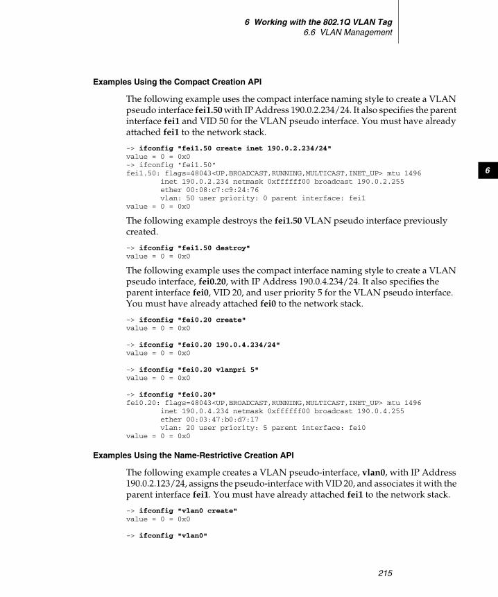
6 Working with the 802.1Q VLAN Tag6.6 VLAN Management
215
6
Examples Using the Compact Creation API
The following example uses the compact interface naming style to create a VLAN pseudo interface fei1.50 with IP Address 190.0.2.234/24. It also specifies the parent interface fei1 and VID 50 for the VLAN pseudo interface. You must have already attached fei1 to the network stack.
-> ifconfig "fei1.50 create inet 190.0.2.234/24"value = 0 = 0x0-> ifconfig "fei1.50"fei1.50: flags=48043<UP,BROADCAST,RUNNING,MULTICAST,INET_UP> mtu 1496
inet 190.0.2.234 netmask 0xffffff00 broadcast 190.0.2.255ether 00:08:c7:c9:24:76vlan: 50 user priority: 0 parent interface: fei1
value = 0 = 0x0
The following example destroys the fei1.50 VLAN pseudo interface previously created.
-> ifconfig "fei1.50 destroy"value = 0 = 0x0
The following example uses the compact interface naming style to create a VLAN pseudo interface, fei0.20, with IP Address 190.0.4.234/24. It also specifies the parent interface fei0, VID 20, and user priority 5 for the VLAN pseudo interface. You must have already attached fei0 to the network stack.
-> ifconfig "fei0.20 create"value = 0 = 0x0
-> ifconfig "fei0.20 190.0.4.234/24"value = 0 = 0x0
-> ifconfig "fei0.20 vlanpri 5"value = 0 = 0x0
-> ifconfig "fei0.20"fei0.20: flags=48043<UP,BROADCAST,RUNNING,MULTICAST,INET_UP> mtu 1496 inet 190.0.4.234 netmask 0xffffff00 broadcast 190.0.4.255 ether 00:03:47:b0:d7:17 vlan: 20 user priority: 5 parent interface: fei0value = 0 = 0x0
Examples Using the Name-Restrictive Creation API
The following example creates a VLAN pseudo-interface, vlan0, with IP Address 190.0.2.123/24, assigns the pseudo-interface with VID 20, and associates it with the parent interface fei1. You must have already attached fei1 to the network stack.
-> ifconfig "vlan0 create" value = 0 = 0x0
-> ifconfig "vlan0"
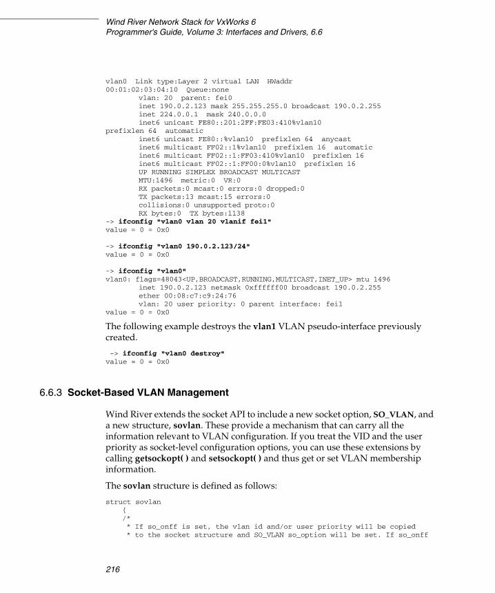
Wind River Network Stack for VxWorks 6Programmer's Guide, Volume 3: Interfaces and Drivers, 6.6
216
vlan0 Link type:Layer 2 virtual LAN HWaddr 00:01:02:03:04:10 Queue:none
vlan: 20 parent: fei0inet 190.0.2.123 mask 255.255.255.0 broadcast 190.0.2.255inet 224.0.0.1 mask 240.0.0.0inet6 unicast FE80::201:2FF:FE03:410%vlan10
prefixlen 64 automaticinet6 unicast FE80::%vlan10 prefixlen 64 anycastinet6 multicast FF02::1%vlan10 prefixlen 16 automaticinet6 multicast FF02::1:FF03:410%vlan10 prefixlen 16inet6 multicast FF02::1:FF00:0%vlan10 prefixlen 16UP RUNNING SIMPLEX BROADCAST MULTICASTMTU:1496 metric:0 VR:0RX packets:0 mcast:0 errors:0 dropped:0TX packets:13 mcast:15 errors:0collisions:0 unsupported proto:0RX bytes:0 TX bytes:1138
-> ifconfig "vlan0 vlan 20 vlanif fei1" value = 0 = 0x0
-> ifconfig "vlan0 190.0.2.123/24" value = 0 = 0x0
-> ifconfig "vlan0" vlan0: flags=48043<UP,BROADCAST,RUNNING,MULTICAST,INET_UP> mtu 1496
inet 190.0.2.123 netmask 0xffffff00 broadcast 190.0.2.255ether 00:08:c7:c9:24:76vlan: 20 user priority: 0 parent interface: fei1
value = 0 = 0x0
The following example destroys the vlan1 VLAN pseudo-interface previously created.
-> ifconfig "vlan0 destroy" value = 0 = 0x0
6.6.3 Socket-Based VLAN Management
Wind River extends the socket API to include a new socket option, SO_VLAN, and a new structure, sovlan. These provide a mechanism that can carry all the information relevant to VLAN configuration. If you treat the VID and the user priority as socket-level configuration options, you can use these extensions by calling getsockopt( ) and setsockopt( ) and thus get or set VLAN membership information.
The sovlan structure is defined as follows:
struct sovlan{/** If so_onff is set, the vlan id and/or user priority will be copied* to the socket structure and SO_VLAN so_option will be set. If so_onff
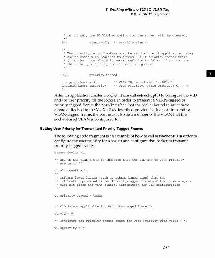
6 Working with the 802.1Q VLAN Tag6.6 VLAN Management
217
6
* is not set, the SO_VLAN so_option for the socket will be cleared.*/int vlan_onoff; /* on/off option */
/** The priority_tagged boolean must be set to true if application using* socket-based vlan requires to egress 802.1P priority-tagged frame* (i.e. the value of vid is zero). Defaults to false. If set to true,* the value specified by the vid will be ignored.*/
BOOL priority_tagged;
unsigned short vid; /* VLAN ID, valid vid: 1..4094 */unsigned short upriority; /* User Priority, valid priority: 0..7 */};
After an application creates a socket, it can call setsockopt( ) to configure the VID and/or user priority for the socket. In order to transmit a VLAN-tagged or priority-tagged frame, the port/interface that the socket bound to must have already attached to the MUX-L2 as described previously. If a port transmits a VLAN-tagged frame, the port must also be a member of the VLAN that the socket-based VLAN is configured for.
Setting User Priority for Transmitted Priority-Tagged Frames
The following code fragment is an example of how to call setsockopt( ) in order to configure the user priority for a socket and configure that socket to transmit priority-tagged frames.
struct sovlan vl;
/* set up the vlan_onoff to indicate that the VID and or User Priority * are valid */
vl.vlan_onoff = 1;/* * Informs lower-layers (such as subnet-based VLAN) that the * information provided is for Priority-tagged frame and that lower-layers * must not alter the VLAN control information for VID configuration*/
vl.priority_tagged = TRUE;
/* VID is not applicable for Priority-tagged frame */
vl.vid = 0;
/* Configure the Priority-tagged frame for User Priority with value 7 */
vl.upriority = 7;
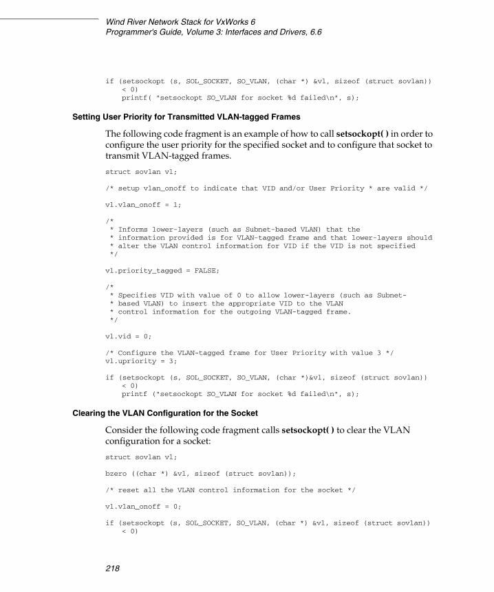
Wind River Network Stack for VxWorks 6Programmer's Guide, Volume 3: Interfaces and Drivers, 6.6
218
if (setsockopt (s, SOL_SOCKET, SO_VLAN, (char *) &vl, sizeof (struct sovlan))< 0)printf( "setsockopt SO_VLAN for socket %d failed\n", s);
Setting User Priority for Transmitted VLAN-tagged Frames
The following code fragment is an example of how to call setsockopt( ) in order to configure the user priority for the specified socket and to configure that socket to transmit VLAN-tagged frames.
struct sovlan vl;
/* setup vlan_onoff to indicate that VID and/or User Priority * are valid */
vl.vlan_onoff = 1;
/* * Informs lower-layers (such as Subnet-based VLAN) that the * information provided is for VLAN-tagged frame and that lower-layers should* alter the VLAN control information for VID if the VID is not specified*/
vl.priority_tagged = FALSE;
/* * Specifies VID with value of 0 to allow lower-layers (such as Subnet- * based VLAN) to insert the appropriate VID to the VLAN * control information for the outgoing VLAN-tagged frame.*/
vl.vid = 0;
/* Configure the VLAN-tagged frame for User Priority with value 3 */vl.upriority = 3;
if (setsockopt (s, SOL_SOCKET, SO_VLAN, (char *)&vl, sizeof (struct sovlan))< 0)printf ("setsockopt SO_VLAN for socket %d failed\n", s);
Clearing the VLAN Configuration for the Socket
Consider the following code fragment calls setsockopt( ) to clear the VLAN configuration for a socket:
struct sovlan vl;
bzero ((char *) &vl, sizeof (struct sovlan));
/* reset all the VLAN control information for the socket */
vl.vlan_onoff = 0;
if (setsockopt (s, SOL_SOCKET, SO_VLAN, (char *) &vl, sizeof (struct sovlan)) < 0)

6 Working with the 802.1Q VLAN Tag6.7 Using the MUX-L2 Show Routines
219
6
printf ("setsockopt SO_VLAN for socket %d failed\n", s);
Getting Configuration Information
The following code fragment is an example of how to call getsockopt( ) to retrieve the VLAN configuration for a socket.
struct sovlan vl;int vsize = sizeof (struct sovlan);
bzero ((char *) &vl, sizeof (struct sovlan));if (getsockopt (s, SOL_SOCKET, SO_VLAN, (char *) &vl, &vsize) < 0)
printf ("getsockopt SO_VLAN for socket %d failed\n", s);if (0 == vl.vlan_onoff)
printf ("No VLAN control info for socket %d\n", s);else
{if (vl.priority_tagged)
printf ("Socket %d Priority-Tagged User Priority %d\n", s,vl.upriority);
elseprintf ("Socket %d VLAN-Tagged VID %d User Priority %d\n", s, vl.vid,
vl.upriority);}
6.7 Using the MUX-L2 Show Routines
For debugging and diagnostic purposes, the MUX-L2 provides muxL2Show( ), muxL2StatShow( ), muxL2VlanShow( ), and muxL2VlanStatShow( ).
Example 6-1 muxL2Show( )
Call muxL2Show( ) to display the configuration of ports registered with the MUX-L2.
-> muxL2Showmax number of physical ports: 16max number of vlans device supports: 16
NOTE: For the VLAN-tagged frame, if getsockopt( ) returns a VID value of 0, this implies that the application uses the socket-based VLAN, chooses not to configure the VID, and relies on the lower-layers (such as subnet-based VLAN) to insert the appropriate VID to the VLAN control information for the outgoing VLAN-tagged frame.

Wind River Network Stack for VxWorks 6Programmer's Guide, Volume 3: Interfaces and Drivers, 6.6
220
number of vlans configured in device: 3number of ports attached to MUX-L2: 2
Device: <fei> Unit: <1> L2 Port Object: 0x10cc040 endObjId: 1Port VID (PVID): 1 Port User Priority: 0Port ingress filter: TRUEPort ingress acceptable frame filter type: Admit vlan-tagged frames onlyHardware supports vlan tagging: FALSEHardware supports vlan mtu: FALSENumber of vid configured for the port: 2Port VLAN membership:
VID 1 Egress: untagged-taggedVID 20 Egress: vlan-tagged
Device: <fei> Unit: <0> L2 Port Object: 0x10e40a0 endObjId: 2Port VID (PVID): 1 Port User Priority: 0Port ingress filter: TRUEPort ingress acceptable frame filter type: Admit All FramesHardware supports vlan tagging: FALSEHardware supports vlan mtu: FALSENumber of vid configured for the port: 2Port VLAN membership:
VID 1 Egress: untagged-taggedVID 100 Egress: vlan-tagged
value = 1 = 0x1
Example 6-2 muxL2VlanShow( )
Calls muxL2VlanShow( ) to display the VLAN configurations maintained by the MUX-L2 on a per-VLAN basis.
-> muxL2VlanShow
VLAN 1: Number of Members: 2 Egress Untagged: 2VLAN 20: Number of Members: 1 Egress Untagged: 0VLAN 100: Number of Members: 1 Egress Untagged: 0
Port to device name mapping:Port 1 -> fei1Port 2 -> fei0
VLAN Membership information:(Legend: 'M' = Member '-' = Unspecified)
VLAN 1 : MM--------------VLAN 20 : M---------------VLAN 100 : -M--------------
VLAN Egress Frame Type:(Legend: 'T' = Vlan-Tagged 'U' = Untagged '-' = Unspecified)
VLAN 1 : UU--------------VLAN 20 : T---------------VLAN 100 : -T--------------
value = 1 = 0x1

6 Working with the 802.1Q VLAN Tag6.7 Using the MUX-L2 Show Routines
221
6
Example 6-3 muxL2StatShow( ) and muxL2VlanStatShow( )
The MUX-L2 also maintains various VLAN statistics on a per-port per-VLAN basis. These statistics are disabled by default for performance reasons. To include these statistics, build MUX-L2 with MUX_L2_VLAN_STATS defined. If VLAN statistics are included, muxL2VlanStatShow( ) and muxL2StatShow( ) can be used to monitor the traffic on a per-port per-VLAN basis.
-> muxL2StatShowfei1 Port Statistics:
Number of received frames discarded due to non-vlanreasons (i.e. Discard Ingress Filtering): 9Number of egress frames discarded due to EgressRules violation: 0
VLAN 1 staticstics:Number of frames received: 0Number of frames transmitted: 0Number of received frames discarded: 0
VLAN 20 staticstics:Number of frames received: 166Number of frames transmitted: 226Number of received frames discarded: 0
fei0 Port Statistics:Number of received frames discarded due to non-vlanreasons (i.e. Discard Ingress Filtering): 0Number of egress frames discarded due to EgressRules violation: 0
VLAN 1 staticstics:Number of frames received: 0Number of frames transmitted: 0Number of received frames discarded: 0
VLAN 100 staticstics:Number of frames received: 393Number of frames transmitted: 486Number of received frames discarded: 0
value = 0 = 0x0
-> muxL2VlanStatShowfei1 VLAN 1 staticstics
Number of frames received: 0Number of frames transmitted: 0Number of received frames discarded: 0
fei0 VLAN 1 staticsticsNumber of frames received:Number of frames transmitted: 0Number of received frames discarded: 0

Wind River Network Stack for VxWorks 6Programmer's Guide, Volume 3: Interfaces and Drivers, 6.6
222
fei1 VLAN 20 staticsticsNumber of frames received: 166Number of frames transmitted: 226Number of received frames discarded: 0
fei0 VLAN 100 staticsticsNumber of frames received: 393Number of frames transmitted: 486Number of received frames discarded: 0
value = 0 = 0x0
223
7Quality of Service
7.1 Introduction 223
7.2 Differentiated Services 224
7.3 Network Interface Output Queues 237
7.1 Introduction
Quality of Service (QoS) refers to the capability of a network to treat some traffic flows differently than others. The most common usage is to give a specific traffic flow a better service than the normal best-effort service.
Different types of flow have different requirements; for example, some flows have restrictions in latency, while others have restrictions in minimum bandwidth, and so on. For example:
■ Interactive traffic, like telnet and SSH, performs better with low latency so that the user does not experience delay when typing.
■ FTP traffic performs better when it can use as much bandwidth as possible; it does not matter if the latency is high or if the data arrives in bursts.
NOTE: The QoS feature is available only in the Wind River Platforms builds of the network stack. The Wind River General Purpose Platform, VxWorks Edition, does not support QoS.
Wind River Network Stack for VxWorks 6Programmer's Guide, Volume 3: Interfaces and Drivers, 6.6
224
Telnet will have a high latency if routers treat all traffic equally, which is the default “best effort” behavior used by most routers. But routers could improve latency if each router identifies the two varieties of flow and lets the telnet packets move ahead of FTP packets that the router has already queued to send on the outgoing interface. Doing so will ordinarily have little effect on the FTP application, since telnet normally uses little bandwidth.
7.2 Differentiated Services
The Differentiated Services (DiffServ) architecture is based on a model in which an edge router classifies traffic entering a network, possibly conditions it (for instance to reduce jitter or latency), and assigns it to different behavior aggregates. It assigns packets to behavior aggregates by setting a single differentiated-services (DS) codepoint in the value of the DS field of the IP datagram (the TOS field for IPv4 or the traffic-class field for IPv6). The core routers of the network then may forward these packets according to the per-hop behavior they associate with each DS codepoint.
To control, create, and delete interface output queues, use the API that is defined in the following file:
installDir/components/ip_net2-6.n/ipnet2/include/ipnet_qos.h
7.2.1 Including DiffServ in a Build
To include DiffServ in a VxWorks build, include the DiffServ build components listed below. You can do this through either Workbench or the vxprj command-line utility.
The following six build components enable DiffServ (there are no build parameters for any of the components):
Differentiated Services (INCLUDE_IPNET_DIFFSERV)the main component for differentiated services
Classifier (INCLUDE_IPNET_CLASSIFIER)classifier component
7 Quality of Service7.2 Differentiated Services
225
7
Simple Marker (INCLUDE_IPNET_DS_SM)component for the simple marker (see SimpleMarker, p.234)
Single Rate Three Color Marker (INCLUDE_IPNET_DS_SRTCM)component for the single-rate, three-color marker (see Single-Rate Three-Color Marker, p.235)
IPCOM QoS commands (INCLUDE_IPQOS_CMD)enables the use of shell commands for configuring DiffServ
IPCOM output queue commands (INCLUDE_IPQUEUE_CONFIG_CMD)enables the use of shell commands for configuring output queues
7.2.2 Using DiffServ
You can configure a DiffServ traffic classifier to run either in behavior aggregate mode or in multi-field mode:
■ In behavior aggregate mode, the classifier looks only at the DS field (the TOS field in IPv4, or the traffic class for IPv6).
■ In multi-field mode, the classifier may look at any field supported by the IPNET classifier—this is slower, but more flexible.
To run in behavior aggregate mode, define the macro IPNET_DIFFSERV_CLASSIFIER_MODE_BA in the file installDir/components/ip_net2-6.n/ipnet2/config/ipnet_config.h; undefine this macro to run in multi-field mode.
Adding a Filter Rule for a Meter/Marker Entity
To add a filter rule for a meter/marker entity when running DiffServ in multi-field mode, you can either call a routine from within a program or use a QC command interactively.
To invoke this operation from within a program, use the following call:
ioctl (sock_fd, SIOCXADSFILTER, &filter);
Where filter is a ds_filter object that describes the filter you are adding (see The ds_filter Class, p.228). The network stack chooses an ID for the filter and stores it in the id member of this object. Use this ID number if you need to refer to this specific filter, for instance if you attach it to a DiffServ meter/marker entity.
You can also use a QC command, which has the following format:

Wind River Network Stack for VxWorks 6Programmer's Guide, Volume 3: Interfaces and Drivers, 6.6
226
qc filter add dev device parent queueID handle filterID [filterArgs] flowid queueID
The arguments to this command are as follows:
dev device The device to which you are attaching the filter, for instance eth0.
parent queueID The identifying number of the container queue to which you are adding the filter.
handle filterID [filterArgs] The filterID is the identifying number of the filter. You may use the following arguments in the filterArgs argument to describe the filter:
proto number
tclass number
srcport range
dstport range
srcaddr address[/prefix]
dstaddr address[/prefix]
flowid queueID The identifying number of the destination queue for packets that match the filter.
For example:
To add a filter identified by the number five to the container queue identified by the number one, so that all TCP packets (protocol number six) are filtered into the queue identified by the number 31, use the following QC command:
> qc filter dev eth0 parent 1 handle 5 proto 6 flowid 31
To add a second filter (identified by the number three) to the same container queue that filters all UDP packets (protocol number 17) that are sent to 2001::/16 into the same queue, use the following QC command:
> qc filter dev eth0 parent 1 handle 3 proto 17 srcaddr 2001::/16 flowid 31
Deleting a Filter Rule from a Meter/Marker Entity
To delete a filter rule from a meter/marker entity when running DiffServ in multi-field mode, you can either call a routine from within a program or use a QC command interactively.
To invoke this operation from within a program, use the following call:
7 Quality of Service7.2 Differentiated Services
227
7
ioctl (sock_fd, SIOCXDDSFILTER, &filter);
In this call, filter is a ds_filter object that describes the filter you are deleting (see The ds_filter Class, p.228). You only need to set the id member of this object in order to specify which filter you want to delete.
You can also use a QC command, which has the following format:
# qc filter del filterID
Creating a Meter/Marker Entity
To create a meter/marker entity, you can either call a routine from within a program or use a QC command interactively.
To invoke this operation from within a program, use the following call:
ioctl (sock_fd, SIOCXDSCREATE, &entity);
In this call, entity is an object of the ds superclass (see The ds Class, p.231). The network stack will fill in the id field of this object. Use this identifying number to identify this entity in future calls.
See 7.2.4 Creating New Meter/Marker Entity Varieties, p.232, for descriptions of the meter/marker entities that are part of the Wind River Network Stack and for instructions on how to add new entities.
Deleting a Meter/Marker Entity
To delete a meter/marker entity, you can either call a routine from within a program or use a QC command interactively.
To invoke this operation from within a program, use the following call:
ioctl (sock_fd, SIOCXDSDESTROY, &entity);
In this call, entity is an object of the ds superclass (see The ds Class, p.231), but you need only fill in the id member of this object in order to sufficiently identify the entity you want to delete.
Mapping a Filter to a Meter/Marker Entity
To map a filter (or DS codepoint if you are operating in multi-field mode) to a meter/marker entity, you can either call a routine from within a program or use a QC command interactively.
Wind River Network Stack for VxWorks 6Programmer's Guide, Volume 3: Interfaces and Drivers, 6.6
228
To invoke this operation from within a program, use the following call:
ioctl (sock_fd, SIOCXADSMAP, &mapping);
In this call, mapping is an object of the ds_map class that describes the mapping you are establishing (see Mapping from a Filter Rule to a Meter Marker Entity, p.231).
Removing a Filter-to-Meter/Marker Entity Mapping
To remove a mapping between a filter (or DS codepoint if you are operating in multi-field mode) and a meter/marker entity, you can either call a routine from within a program or use a QC command interactively.
To invoke this operation from within a program, use the following call:
ioctl (sock_fd, SIOXDDSMAP, &mapping);
In this call, mapping is an object of the ds_map class that describes the mapping that you are removing (see Mapping from a Filter Rule to a Meter Marker Entity, p.231).
7.2.3 Classes
The following sections describe classes of objects associated with DiffServ:
■ ds_filter – see The ds_filter Class, p.228■ ds – see The ds Class, p.231■ ds_map – see Mapping from a Filter Rule to a Meter Marker Entity, p.231
The ds_filter Class
A DiffServ filter rule is instantiated as an object of the ds_filter class (see Figure 7-1).

7 Quality of Service7.2 Differentiated Services
229
7
The members of the classifier_rule class are defined as follows:
mask A mask that indicates which fields must match in order to trigger the filter rule. Construct this mask by ANDing together one or more of the CLS_RULE_x constants:
■ CLS_RULE_DS – DS field■ CLS_RULE_PROTO – protocol field■ CLS_RULE_SADDR – source address■ CLS_RULE_DADDR – destination address■ CLS_RULE_SPORT – source port■ CLS_RULE_DPORT – destination port
ds The value that a packet must have in its DS field in order to trigger the filter rule (assuming the CLS_RULE_DS flag is set in mask). The DS field is the traffic class field for IPv6 and the TOS field for IPv4.
proto The value that a packet must have in its IP header’s protocol field in order to trigger the filter rule (assuming the CLS_RULE_PROTO flag is set in mask).
sport_low The lowest source port a UDP or TCP packet can come from and still trigger the filter rule (assuming the CLS_RULE_SPORT flag is set in mask).
Figure 7-1 The ds_filter and classifier_rule Class
classifier_rulemask : u_shortds : u_charproto : u_charsport_low : u_shortsport_high : u_shortdport_low : u_shortdport_high : u_shortaf : u_charsaddr_prefixlen : u_chardaddr_prefixlen : u_char
ds_filterid : int
rule
in_addr_union
in_addr in6_addr
saddr
daddr

Wind River Network Stack for VxWorks 6Programmer's Guide, Volume 3: Interfaces and Drivers, 6.6
230
sport_high The highest source port a UDP or TCP packet can come from and still trigger the filter rule (assuming the CLS_RULE_SPORT flag is set in mask).
dport_low The lowest destination port a UDP or TCP packet can be destined for and still trigger the filter rule (assuming the CLS_RULE_DPORT flag is set in mask).
dport_high The highest destination port a UDP or TCP packet can be destined for and still trigger the filter rule (assuming the CLS_RULE_DPORT flag is set in mask).
af The address family the packet must belong to in order to trigger the filter rule, either AF_INET or AF_INET6.
saddr_prefixlen The prefix length (mask) that the filter rule uses when it checks whether the source address matches (assuming the CLS_RULE_SADDR flag is set in mask).
daddr_prefixlen The prefix length (mask) that the filter rule uses when it checks whether the destination address matches (assuming the CLS_RULE_DADDR flag is set in mask).
saddr The source address (or network) that packets must match in order to trigger the filter rule (assuming the CLS_RULE_SADDR flag is set in mask).
daddr The destination address (or network) that packets must match in order to trigger the filter rule (assuming the CLS_RULE_DADDR flag is set in mask).

7 Quality of Service7.2 Differentiated Services
231
7
The ds Class
Meter/marker entities are objects of a variety of the ds class (see Figure 7-2).
The members of this class are defined as follows:
id The ID of this meter/marker entity. The network stack sets this during the create operation.
name The name of the meter/marker entity. The names of the two entity varieties that come with the Wind River Network Stack are:
"srTCM" – single-rate, three-color marker
"SimpleMarker" – simple marker
d An object of the specific entity class. All meter/marker entities created by Wind River have an data type that starts with “ds_”, for instance ds_sm (see SimpleMarker, p.234) or ds_srtcm (see Single-Rate Three-Color Marker, p.235). The ds_data pseudoclass is a union of all of these classes.
Mapping from a Filter Rule to a Meter Marker Entity
When an edge router in multi-field mode creates a new classifier rule it gets an ID number in return. When it creates a meter/marker entity, it also gets an ID number in return. The router can search a database that maps between these two varieties of ID value, so that when a packet matches a rule with a particular rule ID value the router can determine the corresponding entity ID value. The database of mappings is a set of ds_map objects (see Figure 7-3).
Figure 7-2 The ds Class
ds
id : intname : char[ ]
d ds_data
ds_sm ds_srtcm

Wind River Network Stack for VxWorks 6Programmer's Guide, Volume 3: Interfaces and Drivers, 6.6
232
The members of this class are as follows:
filter_id The ID of the filter rule.
ds_id The ID of the meter/marker entity that applies to packets that match the filter rule.
For instructions on how to establish a mapping of this sort, see Mapping a Filter to a Meter/Marker Entity, p.227.
7.2.4 Creating New Meter/Marker Entity Varieties
To create a new meter/marker entity variety (other than the simple marker and single-rate three-color marker, which already exist), do the following:
1. Implement all of the routines pointed to by function pointers in the Ipnet_diffserv_handlers structure (see Implement the Function Pointers in the Ipnet_diffserv_handlers Structure, p.232).
2. Define and register a factory function for meter/marker entities (see Define and Register a Factory Function for Meter/Marker Entities, p.233).
Step 1: Implement the Function Pointers in the Ipnet_diffserv_handlers Structure
A meter/marker entity must implement all of the routines pointed to by function pointers in the Ipnet_diffserv_handlers structure, which is defined in installDir/components/ip_net2-6.n/ipnet2/src/ipnet_diffserv.h (see Figure 7-4):
Figure 7-3 The ds_map Class
ds_mapfilter_id : intds_id : int
Figure 7-4 The Ipnet_diffserv_handlers Interface
Ipnet_diffserv_handlers
meter_input( )marker_input( )destroy( )

7 Quality of Service7.2 Differentiated Services
233
7
meter_input You can set this pointer to IP_NULL if this entity will do no metering on the flow passing through it. You should otherwise set it to point to a routine that measures some property of the flow and keeps track of the result in some private data area. The prototype of this routine is as follows:
void myMeterInput (Ipnet_diffserv_handlers * handlers,Ipcom_pkt * packet)
marker_input You can set this pointer to IP_NULL if this entity will do no (re)marking of packets. Otherwise set this to point to a routine that marks the packet based on the configuration of the meter/marker or the property measured by the meter function. Your routine may write directly into the DS field of the Ipcom_pkt that it receives as the pkt argument. pkt->ipstart is the offset into the pkt->data area at which the IP header is stored. The prototype of this routine is as follows:
void myMarkerInput (Ipnet_diffserv_handlers * handlers,Ipcom_pkt * packet)
destroy Set this pointer to point to a routine that frees all resources held by the meter/marker. Do not set this pointer to IP_NULL. The prototype of this routine is as follows:
void myDestroy (Ipnet_diffserv_handlers * handlers);
Step 2: Define and Register a Factory Function for Meter/Marker Entities
Define a factory function for the new meter/marker entity and register it with the network stack. You must register the factory function as an Ipnet_diffserv_handlers_template.
typedef struct Ipnet_diffserv_handlers_template_struct{const char * name;Ipnet_diffserv_ctor create;} Ipnet_diffserv_handlers_template;
The fields in this structure are defined as follows:
name The name of the meter/marker entity. The network stack associates this name with the create routine below, so that the stack calls this function when meter/marker entity structures (ds objects) with this name are passed to the SIOCXDSCREATE I/O control operation (see Creating a Meter/Marker Entity, p.227).
Wind River Network Stack for VxWorks 6Programmer's Guide, Volume 3: Interfaces and Drivers, 6.6
234
create The create routine the network stack calls for meter/marker entities whose name members match name, above. The stack passes data (the d member of the entity’s ds object) as the first argument to this routine. This routine has the following prototype:
int myCreate (void * arg, Ipnet_diffserv_handlers ** phandler);
For the network stack to be able to use the new meter/marker entity type, you must register the factory function by passing it in to ipnet_diffserv_register_ctor( ) from the ipnet_diffserv_init( ) routine, which is defined in:
installDir/components/ip_net2-6.n/ipnet2/src/ipnet_diffserv.c
For example, the single-rate three-color marker declares a routine called ipnet_diffserv_srtcm_template( ), which returns a static variable of type Ipnet_diffserv_handlers_template that it initializes with a name and a pointer to a constructor function, so its factory registration call looks like this:
ipnet_diffserv_register_ctor (ipnet_diffserv_srtcm_template ())
7.2.5 Using Existing Meter/Marker Entity Varieties
The following two meter/markers are already implemented and part of the stack:
■ a simple marker (SimpleMarker, see SimpleMarker, p.234)
■ a single-rate, three-color marker (srTCM, see Single-Rate Three-Color Marker, p.235)
SimpleMarker
The simple marker, SimpleMarker, is defined in:
installDir/components/ip_net2-6.n/ipnet2/src/ipnet_ds_sm.c.
The simple marker copies a specific DS value into each IP header DS field on all packets that match a filter and can also set the drop precedence on every packet that matches.
The definition of the ds_sm class is shown in Figure 7-5.
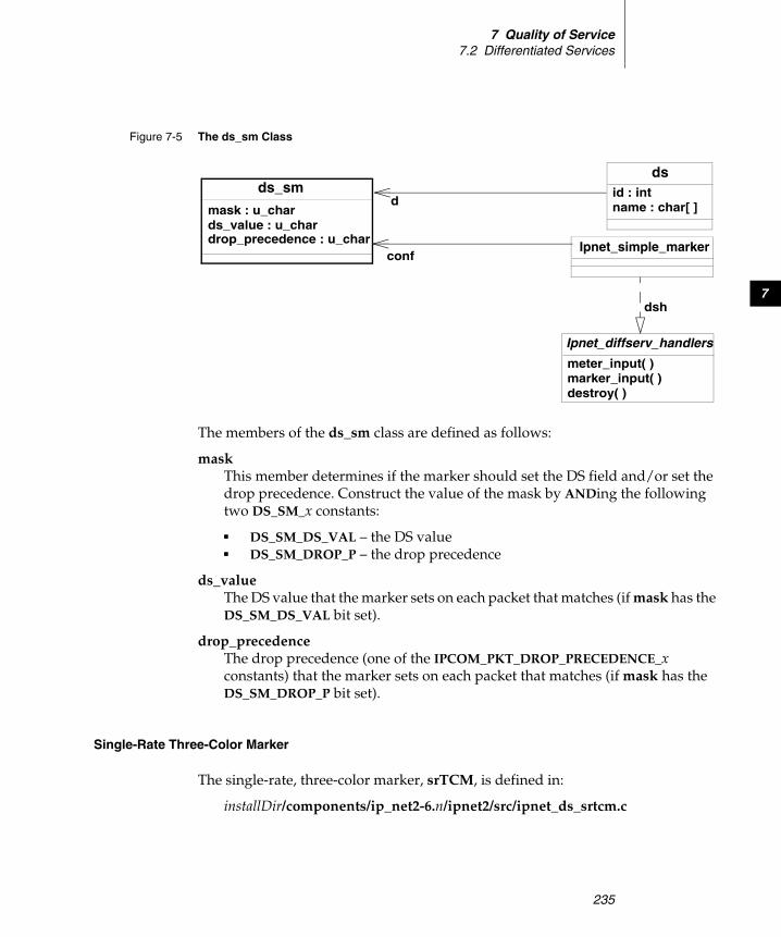
7 Quality of Service7.2 Differentiated Services
235
7
The members of the ds_sm class are defined as follows:
mask This member determines if the marker should set the DS field and/or set the drop precedence. Construct the value of the mask by ANDing the following two DS_SM_x constants:
■ DS_SM_DS_VAL – the DS value■ DS_SM_DROP_P – the drop precedence
ds_value The DS value that the marker sets on each packet that matches (if mask has the DS_SM_DS_VAL bit set).
drop_precedence The drop precedence (one of the IPCOM_PKT_DROP_PRECEDENCE_x constants) that the marker sets on each packet that matches (if mask has the DS_SM_DROP_P bit set).
Single-Rate Three-Color Marker
The single-rate, three-color marker, srTCM, is defined in:
installDir/components/ip_net2-6.n/ipnet2/src/ipnet_ds_srtcm.c
Figure 7-5 The ds_sm Class
dsid : intname : char[ ]d
ds_sm
mask : u_chards_value : u_chardrop_precedence : u_char
Ipnet_simple_markerconf
Ipnet_diffserv_handlers
meter_input( )marker_input( )destroy( )
dsh

Wind River Network Stack for VxWorks 6Programmer's Guide, Volume 3: Interfaces and Drivers, 6.6
236
The single-rate, three-color marker meters the byte rate of a flow and marks packets as green, yellow, or red. The shaper prioritizes green packets over yellow packets and yellow packet over red packets. See RFC 2697 for a complete description of the srTCM meter/marker.
The definition of the ds_srtcm class is shown in Figure 7-6.
The members of the ds_srtcm class are as follows:
mode The mode in which the srTCM marker is operating. This can be either DS_SRTCM_MODE_COLOR_BLIND or DS_SRTCM_MODE_COLOR_AWARE.
CIR The Committed Information Rate (bytes/second): the maximum, long term, data rate the flow can have and still have the marker mark it as green.
CBS The Committed Burst Rate (bytes): the maximum size of the token bucket for green packets.
Figure 7-6 The ds_srtcm Class
ds
id : intname : char[ ]d
ds_srtcmmode : u_charCIR : u_longCBS : u_long
Ipnet_srtcmconf
Ipnet_diffserv_handlers
meter_input( )marker_input( )destroy( )
dsh
color : intTc : Ip_u32Te : Ip_u32msec : Ip_u32
EBS : u_longds_green : u_chards_yellow : u_chards_red : u_char
7 Quality of Service7.3 Network Interface Output Queues
237
7
EBS The Excess Burst Rate (bytes): the maximum size of the token bucket for yellow packets.
ds_green The DS value that the marker gives to green packets.
ds_yellow The DS value that the marker gives to yellow packets.
ds_red The DS value that the marker gives to red packets.
7.3 Network Interface Output Queues
You can attach an interface output queue to every network interface in the network stack. All packets that the network stack sends through such an interface pass through a queue, and the queue can meter and enforce a maximum throughput on the packet flow.
There are two varieties of interface output queues in the network stack:
■ Leaf queues, in which the packets are stored. These cannot have child queues. (See 7.3.2 Leaf Queues, p.242.)
■ Container queues, which have one or more child queues (which can be either leaf queues or container queues) and a set of rules that determine which child queue to queue each packet in (see 7.3.3 Container Queues, p.247).
The API that you use to create, control, and delete interface output queues is defined in installDir/components/ip_net2-6.n/ipnet2/include/ipnet_qos.h.
The ifqueue_qos class
To establish a queue, set the members of an object of the ifqueue_qos class and then attach this queue object to an interface using one of the techniques described in Adding an Interface Output Queue, p.240. The ifqueue_qos class is shown in Figure 7-7.
NOTE: Set at least one of CBS or EBS to be greater than zero and at least as big as the largest possible packet in the flow.
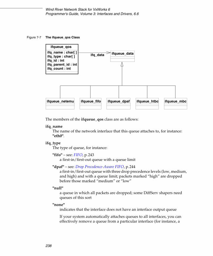
Wind River Network Stack for VxWorks 6Programmer's Guide, Volume 3: Interfaces and Drivers, 6.6
238
The members of the ifqueue_qos class are as follows:
ifq_name The name of the network interface that this queue attaches to, for instance: "eth0".
ifq_type The type of queue, for instance:
"fifo" – see: FIFO, p.243a first-in/first-out queue with a queue limit
"dpaf" – see: Drop Precedence-Aware FIFO, p.244a first-in/first-out queue with three drop precedence levels (low, medium, and high) and with a queue limit; packets marked “high” are dropped before those marked “medium” or “low”
"null" a queue in which all packets are dropped; some DiffServ shapers need queues of this sort
"none" indicates that the interface does not have an interface output queue
If your system automatically attaches queues to all interfaces, you can effectively remove a queue from a particular interface (for instance, a
Figure 7-7 The ifqueue_qos Class
ifqueue_qos
ifq_name : char[ ]ifq_type : char[ ] ifq_data ifqueue_data
ifq_id : intifq_parent_id : intifq_count : int
ifqueue_netemu ifqueue_fifo ifqueue_dpaf ifqueue_htbc ifqueue_mbc

7 Quality of Service7.3 Network Interface Output Queues
239
7
pseudo-interface that you do not want to filter) by setting its queue type to none.
"netemu" – see: Network Emulator, p.245can add latency, and can reorder, drop, and corrupt packets; you can use this to test various network conditions
"mbc" – see: Multi-Band Container (MBC), p.249holds an array of queues, arranged in order of priority (the lower the index in the array, the higher the priority); packets dequeue from the container in order of priority
"htbc" – see: Hierarchy Token Bucket Container (HTBC), p.250holds a set of queues that are not prioritized relative to each other; packets dequeue from these queues in a round-robin fashion
ifq_id The identifying number of the queue. In GET operations, if you set this to IFQ_ID_NONE, the operation returns the root queue, otherwise it returns the queue with this ID.
In SET operations, you can set this to a specific ID if you want to operate on a specific queue, or you can set this to IFQ_ID_NONE if you want the stack to select a unique ID. If the specified queue ID already exists, a SET operation replaces the queue. If you replace a container queue, this removes all of its children.
All queues attached to a particular interface have unique identifying numbers, but the same number may be used to refer to different queues that are attached to different interfaces.
ifq_parent_id The ID of the parent of this queue if this is a child queue, or IFQ_ID_NONE, if this is the root queue.
ifq_count (Read-only.) The number of packets in this queue, if it is a leaf queue, or the sum of packets in all of its child queues, if it is a container queue.
ifq_data An object that defines the characteristics of the particular type of queue. This may be an object of a queue class of your own invention, or one of the following:
■ ifqueue_fifo – see: FIFO, p.243■ ifqueue_dpaf – see: Drop Precedence-Aware FIFO, p.244■ ifqueue_netemu – see: Network Emulator, p.245

Wind River Network Stack for VxWorks 6Programmer's Guide, Volume 3: Interfaces and Drivers, 6.6
240
■ ifqueue_mbc – see: Multi-Band Container (MBC), p.249■ ifqueue_htbc – see: Hierarchy Token Bucket Container (HTBC), p.250
7.3.1 Operations
This section describes the various things you can do with output queues:
■ Adding an Interface Output Queue, p.240■ Getting an Object that Describes an Interface Output Queue, p.241■ Adding a Filter Rule to a Container Queue, p.241■ Deleting a Filter Rule from a Container Queue, p.242
Adding an Interface Output Queue
To add an interface output queue to a network interface, or to replace one that was previously added, you can either call a routine from within a program or use a QC command interactively.
To invoke this operation from within a program, use the following call:
ioctl (sock_fd, SIOCSIFQUEUE, &queue);
Where queue is a ifqueue_qos object that describes the leaf or container queue you are adding (see The ifqueue_qos class, p.237).
If the ifq_id member of the ifqueue_qos object matches that of a queue that is already attached to the interface, this operation will replace that queue with the one described by queue.
You can also use the following QC command:
# qc [-V virtualRouter] queue add [parameters]
For instance, if you want to test how your system would work under conditions when there was 100 millisecond latency on interface lo0, you could create a network emulator queue on that device that simulates such latency, with the following QC command:
# qc queue add dev lo0 netemu limit 10 min_latency 100 max_latency 100
If you want to rate-limit all traffic on interface eth0 to two Mbits per second, you could do this by establishing a rate-limited HTBC queue with the following command:
# qc queue add dev eth0 htbc rate 2000kbps

7 Quality of Service7.3 Network Interface Output Queues
241
7
Getting an Object that Describes an Interface Output Queue
To get an object that describes an interface output queue on a network interface, you can either call a routine from within a program or use a QC command interactively.
To invoke this operation from within a program, use the following call:
ioctl (sock_fd, SIOCGIFQUEUE, &queue);
Where queue is a ifqueue_qos object (see The ifqueue_qos class, p.237).
If you call this with the ifq_id field of queue set to IFQ_ID_NONE, this routine will fill queue so that it describes the root queue on this interface, otherwise it will fill queue so that it describes the queue matching ifq_id.
You can also use a QC command, which has the following format:
# qc [-V virtualRouter] queue show [parameters]
Adding a Filter Rule to a Container Queue
To add a filter rule to a container queue on a network interface, you can either call a routine from within a program or use a QC command interactively.
To invoke this operation from within a program, use the following call:
ioctl (sock_fd, SIOCXAIFQFILTER, &filter);
In this call filter is an ifqueue_filter object that describes the filter you are adding (see Filter Rules, p.247).
You can also use a QC command, which has the following format:
qc filter add dev device parent queueID handle filterID [filterArgs] flowid queueID
The arguments to this command are as follows:
dev device The device to which you are attaching the filter, for instance eth0.
parent queueID The identifying number of the container queue to which you are adding the filter.
handle filterID [filterArgs] The filterID is the identifying number of the filter. You may use the following arguments in the filterArgs argument to describe the filter:

Wind River Network Stack for VxWorks 6Programmer's Guide, Volume 3: Interfaces and Drivers, 6.6
242
proto number
tclass number
srcport range
dstport range
srcaddr address[/prefix]
dstaddr address[/prefix]
flowid queueID The identifying number of the destination queue for packets that match the filter.
For example:
To add a filter identified by the number five to the container queue identified by the number one, so that all TCP packets (protocol number six) are filtered into the queue identified by the number 31, use the following QC command:
# qc filter dev eth0 parent 1 handle 5 proto 6 flowid 31
To add a second filter (identified by the number three) to the same container queue that filters all UDP packets (protocol number 17) that are sent to 2001::/16 into the same queue, use the following QC command:
# qc filter dev eth0 parent 1 handle 3 proto 17 srcaddr 2001::/16 flowid 31
Deleting a Filter Rule from a Container Queue
To delete a filter rule from a container queue on a network interface, you can either call a routine from within a program or use a QC command interactively.
To invoke this operation from within a program, use the following call:
ioctl (sock_fd, SIOCXDIFQFILTER, filter);
In this call filter is an ifqueue_filter object that describes the filter you are removing (see Filter Rules, p.247).
You can also use a QC command, which has the following format:
# qc [-V virtualRouter] filter del [parameters]
7.3.2 Leaf Queues
Leaf queues cannot have children and you cannot assign filter rules to them.
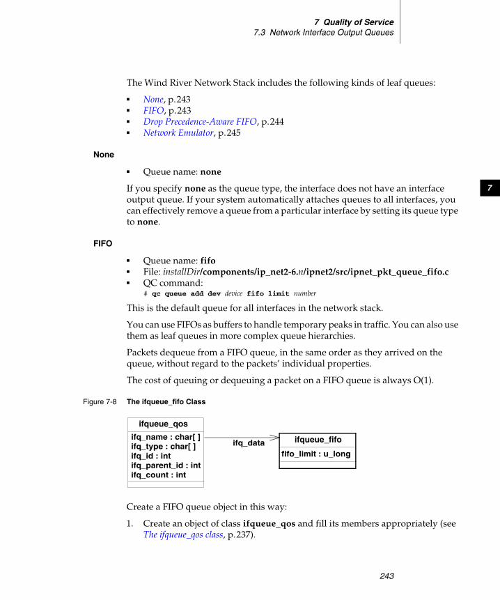
7 Quality of Service7.3 Network Interface Output Queues
243
7
The Wind River Network Stack includes the following kinds of leaf queues:
■ None, p.243■ FIFO, p.243■ Drop Precedence-Aware FIFO, p.244■ Network Emulator, p.245
None
■ Queue name: none
If you specify none as the queue type, the interface does not have an interface output queue. If your system automatically attaches queues to all interfaces, you can effectively remove a queue from a particular interface by setting its queue type to none.
FIFO
■ Queue name: fifo ■ File: installDir/components/ip_net2-6.n/ipnet2/src/ipnet_pkt_queue_fifo.c ■ QC command:
# qc queue add dev device fifo limit number
This is the default queue for all interfaces in the network stack.
You can use FIFOs as buffers to handle temporary peaks in traffic. You can also use them as leaf queues in more complex queue hierarchies.
Packets dequeue from a FIFO queue, in the same order as they arrived on the queue, without regard to the packets’ individual properties.
The cost of queuing or dequeuing a packet on a FIFO queue is always O(1).
Create a FIFO queue object in this way:
1. Create an object of class ifqueue_qos and fill its members appropriately (see The ifqueue_qos class, p.237).
Figure 7-8 The ifqueue_fifo Class
ifqueue_qos
ifq_name : char[ ]ifq_type : char[ ] ifq_data ifqueue_fifo
ifq_id : intifq_parent_id : intifq_count : int
fifo_limit : u_long

Wind River Network Stack for VxWorks 6Programmer's Guide, Volume 3: Interfaces and Drivers, 6.6
244
2. Set the ifq_type member of that object to "fifo".
3. Create an object of class ifqueue_fifo (see Figure 7-8) and set its fifo_limit member to the maximum number of packets that can be stored in the queue.
4. Set the ifq_data member of the ifqueue_qos object to the ifqueue_fifo object.
Drop Precedence-Aware FIFO
■ Queue name: dpaf ■ File: installDir/components/ip_net2-6.n/ipnet2/src/ipnet_pkt_queue_dpaf.c ■ QC command:
# qc queue add dev device dpaf limit number
Drop Precedence-Aware FIFO queues (DPAFs) work as normal FIFOs until the maximum number of packets in the queue is exceeded. If the limit is exceeded, a DPAF checks the drop precedence of the new packet. The following outcomes are possible:
■ reject this packet if is has high drop precedence
■ drop a high-drop-precedence packet from the queue and replace it with the new packet if this packet has medium or low drop precedence
■ drop a medium-drop-precedence packet from the queue and replace it with the new packet if this packet has low drop precedence
■ reject this packet if there are no packets in the queue with higher drop precedence that the DPAF can drop
The extra overhead compared to FIFO makes this queue slower. The cost of queuing/dequeuing a packet is O(log(n)), where n is the number of packets in the queue.
Create a FIFO queue object in this way:
1. Create an object of class ifqueue_qos and fill its members appropriately (see The ifqueue_qos class, p.237).
Figure 7-9 The ifqueue_dpaf Class
ifqueue_qos
ifq_name : char[ ]ifq_type : char[ ] ifq_data ifqueue_dpaf
ifq_id : intifq_parent_id : intifq_count : int
dpaf_limit : u_long
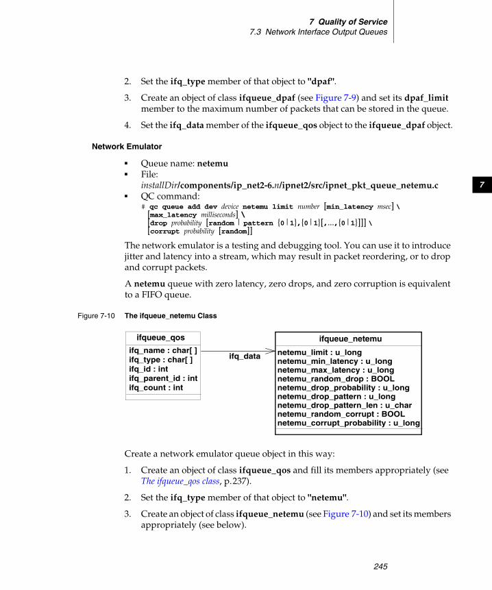
7 Quality of Service7.3 Network Interface Output Queues
245
7
2. Set the ifq_type member of that object to "dpaf".
3. Create an object of class ifqueue_dpaf (see Figure 7-9) and set its dpaf_limit member to the maximum number of packets that can be stored in the queue.
4. Set the ifq_data member of the ifqueue_qos object to the ifqueue_dpaf object.
Network Emulator
■ Queue name: netemu ■ File:
installDir/components/ip_net2-6.n/ipnet2/src/ipnet_pkt_queue_netemu.c ■ QC command:
# qc queue add dev device netemu limit number [min_latency msec] \ [max_latency milliseconds] \ [drop probability [random | pattern {0|1},{0|1}[,...,{0|1}]]] \ [corrupt probability [random]]
The network emulator is a testing and debugging tool. You can use it to introduce jitter and latency into a stream, which may result in packet reordering, or to drop and corrupt packets.
A netemu queue with zero latency, zero drops, and zero corruption is equivalent to a FIFO queue.
Create a network emulator queue object in this way:
1. Create an object of class ifqueue_qos and fill its members appropriately (see The ifqueue_qos class, p.237).
2. Set the ifq_type member of that object to "netemu".
3. Create an object of class ifqueue_netemu (see Figure 7-10) and set its members appropriately (see below).
Figure 7-10 The ifqueue_netemu Class
ifqueue_qos
ifq_name : char[ ]ifq_type : char[ ] ifq_data
ifqueue_netemu
ifq_id : intifq_parent_id : intifq_count : int
netemu_limit : u_longnetemu_min_latency : u_longnetemu_max_latency : u_longnetemu_random_drop : BOOLnetemu_drop_probability : u_long
netemu_random_corrupt : BOOLnetemu_corrupt_probability : u_long
netemu_drop_pattern : u_longnetemu_drop_pattern_len : u_char

Wind River Network Stack for VxWorks 6Programmer's Guide, Volume 3: Interfaces and Drivers, 6.6
246
4. Set the ifq_data member of the ifqueue_qos object to the ifqueue_netemu object.
The members of the ifqueue_netemu class are as follows:
netemu_limit The maximum number of packets that can be stored in this queue.
netemu_min_latency netemu_max_latency
The minimum and maximum latency that the emulator adds to each packet, in milliseconds. The emulator will evenly distribute the latency on individual packets between [netemu_min_latency..netemu_max_latency].
netemu_random_drop netemu_drop_probabilitynetemu_drop_patternnetemu_drop_pattern_len
Set netemu_random_drop to TRUE to drop individual packets with the probability of 1/netemu_drop_probability. Set netemu_random_drop to FALSE to drop a packet every netemu_drop_probability packets. For example, if you set netemu_drop_probability to 4, setting netemu_random_drop to FALSE means the emulator drops every fourth packet, while setting it to TRUE means that for each packet there is a one-in-four probability that the emulator will drop it.
You can also set netemu_drop_pattern to a bitmask that represents a regular pattern of netemu_drop_pattern_len bits, with bits marked “1” representing dropped packets, so that, for instance, the pattern 00000011 (netemu_drop_pattern = 0x00000003, netemu_drop_pattern_len = 8)will drop the last two of every eight packets.
netemu_random_corrupt netemu_corrupt_probability
Set netemu_random_corrupt to TRUE to corrupt individual packets with the probability of 1/netemu_corrupt_probability. Set netemu_random_corrupt to FALSE to corrupt a packet every netemu_corrupt_probability packets. For example, if you set netemu_corrupt_probability to 4, setting netemu_random_corrupt to FALSE means the emulator corrupts every fourth packet, while setting it to TRUE means that for each packet there is a one-in-four probability that the emulator will corrupt it.

7 Quality of Service7.3 Network Interface Output Queues
247
7
7.3.3 Container Queues
A container queue contains one or more child queues (child queues may be container queues or leaf queues or a combination of both). Filter rules determine which child queue the container queue stores a particular packet in.
The Container Superclass
All container classes are subclasses of the ifqueue_container class (which is to say that the first member of the structure that defines a container class is an ifqueue_container structure), see Figure 7-11.
The members of this class are as follows:
child_count the number of child queues this container has (a child queue that is a container queue only counts as a single child even if it in turn has multiple children)
child_ids an array that contains the queue IDs of each of the child queues
Filter Rules
You may attach filter rules to container queues (see Adding a Filter Rule to a Container Queue, p.241). These rules control in which child queue a container queue should place packets. If a packet does not match any rule, the container queue queues the packet on its default child queue.
Figure 7-12 shows the ifqueue_filter class, which describes a filter rule.
Figure 7-11 The ifqueue_container Superclass
ifqueue_container
child_count : intchild_ids : int[ ]
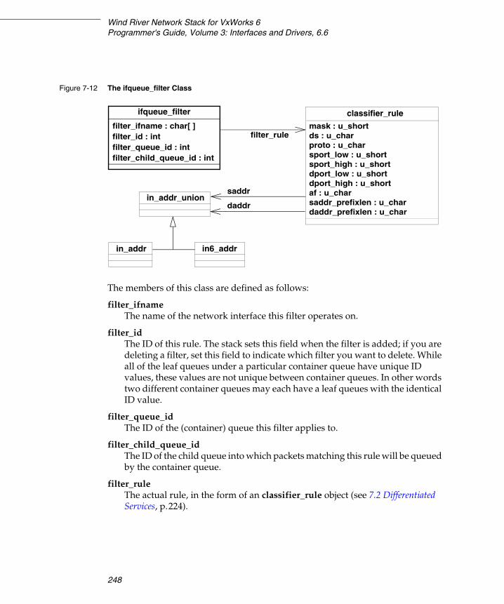
Wind River Network Stack for VxWorks 6Programmer's Guide, Volume 3: Interfaces and Drivers, 6.6
248
The members of this class are defined as follows:
filter_ifname The name of the network interface this filter operates on.
filter_id The ID of this rule. The stack sets this field when the filter is added; if you are deleting a filter, set this field to indicate which filter you want to delete. While all of the leaf queues under a particular container queue have unique ID values, these values are not unique between container queues. In other words two different container queues may each have a leaf queues with the identical ID value.
filter_queue_id The ID of the (container) queue this filter applies to.
filter_child_queue_id The ID of the child queue into which packets matching this rule will be queued by the container queue.
filter_rule The actual rule, in the form of an classifier_rule object (see 7.2 Differentiated Services, p.224).
Figure 7-12 The ifqueue_filter Class
ifqueue_filter
filter_ifname : char[ ]
filter_queue_id : intfilter_id : int filter_rule
classifier_rule
filter_child_queue_id : int
mask : u_shortds : u_charproto : u_charsport_low : u_shortsport_high : u_shortdport_low : u_shortdport_high : u_shortaf : u_charsaddr_prefixlen : u_chardaddr_prefixlen : u_char
in_addr_union
in_addr in6_addr
saddr
daddr

7 Quality of Service7.3 Network Interface Output Queues
249
7
Available Container Queues
The Wind River Network Stack includes the following container queues:
■ Multi-Band Container (MBC), p.249■ Hierarchy Token Bucket Container (HTBC), p.250
Multi-Band Container (MBC)
■ Queue name: MBC ■ File: installDir/components/ip_net2-6.n/ipnet2/src/ipnet_pkt_queue_mbc.c ■ QC command:
# qc queue add dev device mbc bands number [default_band number]
An MBC container queue keeps an array of child queues (bands) in decreasing priority. An MBC queue always dequeues packets from the first non-empty queue in its array of queues.
You can use this variety of container queue when certain kinds of traffic, such as signalling, must transmit as quickly as possible, while other traffic, like e-mail, can wait for low-traffic conditions.
When you create an MBC queue, it initially has an array of FIFO child queues. You may replace these with queues of another variety by issuing an SIOCSIFQUEUE I/O control call (see Adding an Interface Output Queue, p.240).
Define an MBC queue by setting the ifq_type member of the ifqueue_qos structure to "mbc" and the ifq_data member of the ifqueue_qos structure to an object of the ifqueue_mbc class. See Figure 7-13.

Wind River Network Stack for VxWorks 6Programmer's Guide, Volume 3: Interfaces and Drivers, 6.6
250
The members of this class are defined as follows:
mbc_container The base class for container queues.
mbc_bands The number of bands (child queues) that this container queue manages. You may only set this member prior to the time you create the MBC queue.
mbc_default_band Which of the bands (child queues) the MBC container queue puts a packet into if that packet does not match any of the filter rules. This is an index value in the range [0..mbc_bands).
Hierarchy Token Bucket Container (HTBC)
■ Queue name: HTBC ■ File: installDir/components/ip_net2-6.n/ipnet2/src/ipnet_pkt_queue_htbc.c ■ QC command:
# qc queue add dev device htbc rate rate [burst number]
Use the HTBC queue when you want to control the bandwidth usage on an interface. The queue calculates the data rate by taking the sum of bandwidth used by all children; it calculates this when it dequeues packets. It considers all children
Figure 7-13 The ifqueue_mbc Class
ifqueue_mbc
mbc_bands : u_longmbc_default_band : u_long
mbc_containerifqueue_container
child_count : intchild_ids : int[ ]
ifqueue_qos
ifq_name : char[ ]ifq_type : char[ ] = "mbc"
ifq_data
ifq_id : intifq_parent_id : intifq_count : int

7 Quality of Service7.3 Network Interface Output Queues
251
7
to have the same priority, so it dequeues packets from the child queues in a round-robin fashion.
You can add or delete child queues from an HTBC container queue throughout the lifetime of the HTBC. When you create an HTBC, it comes with a single child FIFO queue, the default queue, attached to it. You can add more queues, or replace this default queue with one of another variety, by using the SIOCSIFQUEUE I/O control call (see Adding an Interface Output Queue, p.240).
Define an HTBC queue by setting the ifq_type member of the ifqueue_qos structure to "htbc" and the ifq_data member of the ifqueue_qos structure ifqueue_htbc class (see Figure 7-14).
The members of this class are defined as follows:
htbc_container The base class for containers.
htbc_byterate The maximum bandwidth, in bytes per second, at which this queue may send.
Figure 7-14 The ifqueue_htbc Class
ifqueue_htbc
htbc_byterate : u_long
htbc_default_id : inthtbc_token_limit : u_long
htbc_container ifqueue_container
child_count : intchild_ids : int[ ]
ifqueue_qos
ifq_name : char[ ]ifq_type : char[ ] = "htbc"
ifq_data
ifq_id : intifq_parent_id : intifq_count : int
Wind River Network Stack for VxWorks 6Programmer's Guide, Volume 3: Interfaces and Drivers, 6.6
252
htbc_token_limit The maximum number of tokens this queue can have. Each byte that an HTBC container queue dequeues from one of its children and sends consumes one token. You must set this value to be greater than the MTU (maximum transmission unit) of the interface you attach the queue to. A reasonable value might be in the range htbc_byterate/100 to htbc_byterate. A larger value results in HTBC dropping fewer packets during temporary bursts in the flow, so the actual value depends on the acceptable level of “burstiness.”
htbc_default_id The ID number of the default queue, into which HTBC places all packets that do not match any filter rule.
7.3.4 Adding a New Queue Type
Create a new leaf queue variety by adding its structure to the ifqueue_data union (see The ifqueue_qos class, p.237), implementing all routines in the Ipnet_pkt_queue structure (see Figure 7-15), registering an instance of that type with the ipnet_pkt_queue_register( ) routine.
NOTE: The Wind River Network Stack registers its queues, like the FIFO and HTBC queues, in the ipnet_pkt_queue_init( ) routine, which is located in installDir/components/ip_net2-6.n/ipnet2/src/ipnet_pkt_queue.c. You may want to register any new queues you add at the same time, which you can do by changing this routine to make additional registration calls.
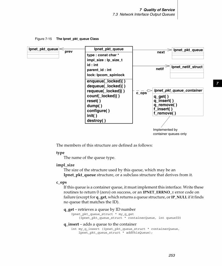
7 Quality of Service7.3 Network Interface Output Queues
253
7
The members of this structure are defined as follows:
type The name of the queue type.
impl_size The size of the structure used by this queue, which may be an Ipnet_pkt_queue structure, or a subclass structure that derives from it.
c_ops If this queue is a container queue, it must implement this interface. Write these routines to return 0 (zero) on success, or an IPNET_ERRNO_x error code on failure (except for q_get, which returns a queue structure, or IP_NULL if it finds no queue that matches the ID).
q_get – retrieves a queue by ID numberIpnet_pkt_queue_struct * my_q_get
(Ipnet_pkt_queue_struct * containerQueue, int queueID)
q_insert – adds a queue to the containerint my_q_insert (Ipnet_pkt_queue_struct * containerQueue,
Ipnet_pkt_queue_struct * addThisQueue);
Figure 7-15 The Ipnet_pkt_queue Class
Ipnet_pkt_queue
type : const char *
id : intparent_id : int
enqueue[_locked]( )dequeue[_locked]( )
impl_size : Ip_size_t
c_opsIpnet_pkt_queue_container
nextIpnet_pkt_queue
Ipnet_netif_structnetif
count[_locked]( )reset( )dump( )
requeue[_locked]( )
configure( )init( )destroy( )
q_get( )q_insert( )q_remove( )f_insert( )f_remove( )
prevIpnet_pkt_queue
Implemented bycontainer queues only
lock: Ipcom_spinlock
Wind River Network Stack for VxWorks 6Programmer's Guide, Volume 3: Interfaces and Drivers, 6.6
254
q_remove – removes a queue from the containerint my_q_remove (Ipnet_pkt_queue_struct * containerQueue,
Ipnet_pkt_queue_struct * removeThisQueue);
f_insert – adds a filter to a queueint my_f_insert (Ipnet_pkt_queue_struct * containerQueue,
int filterID, classifier_rule * rule, int childQueueID);
f_remove – removes a filter from a queueint my_f_remove (Ipnet_pkt_queue_struct * containerQueue,
int filterID)
enqueue or enqueue_locked Enqueues a packet on this queue. This routine has the following prototype:
int myEnqueue (struct Ipnet_pkt_queue_struct * queue, Ipcom_pkt * packet)
Write this routines to return 0 (zero) on success, or an IPNET_ERRNO_x error code on failure.
dequeue or dequeue_locked Dequeues a packet from this queue. This routine has the following prototype:
Ipcom_pkt * myDequeue (Ipnet_pkt_queue_struct * queue)
Write this routine to return the next packet (according to the rules of the queue), or IP_NULL if the queue is empty.
requeue or requeue_locked Puts a packet back on the queue that was removed from the queue with the dequeue function. This routine has the following prototype:
void myRequeue (Ipnet_pkt_queue_struct * queue, Ipcom_pkt * packet);
count or count_locked Returns the number of packets in this queue, or the sum of packets in all child queues if this is a container queue. This routine has the following prototype:
int myCount (Ipnet_pkt_queue_struct * queue);
reset Removes all packets from the queue and resets the internal state of the queue. This routine has the following prototype:
void myReset (Ipnet_pkt_queue_struct * queue);
dump Fills an ifqueue_x structure with the current configuration of this queue. This routine has the following prototype:
void myDump (Ipnet_pkt_queue_struct * queue,union ifqueue_data * data);
7 Quality of Service7.3 Network Interface Output Queues
255
7
Write this routine so that it fills the data structure with the configuration information specific to this queue.
configure Configures the queue based on the ifqueue_x structure for this queue, found in the data parameter. This routine has the following prototype:
int myConfigure (Ipnet_pkt_queue_struct * queue,union ifqueue_data * data);
Write this routine so that it returns the number of elements that may be placed in the queue.
init The routine that initializes the queue after memory has been allocated for it. This routine has the following prototype:
int myInit (Ipnet_pkt_queue_struct * queue);
Write this routines to return 0 (zero) on success, or an IPNET_ERRNO_x error code on failure.
destroy The routine that frees all resources allocated by this queue. This routine has the following prototype:
void myDestroy (Ipnet_pkt_queue_struct * queue);
NOTE: Do not set the remaining fields of this structure, such as id, parent_id, netif, prev, and next.

Wind River Network Stack for VxWorks 6Programmer's Guide, Volume 3: Interfaces and Drivers, 6.6
256
257
8Ingress Traffic Prioritization
8.1 Introduction 257
8.2 Factors to Consider Before Using Ingress Filtering 258
8.3 Building VxWorks to Include Ingress Traffic Prioritization 260
8.4 Implementing an Ingress Filter Routine 261
8.1 Introduction
By default, the network stack treats all packets that arrive at an interface equally and processes them in the order of their arrival. Ingress traffic prioritization is a quality of service (QoS) feature that allows you to assign priorities to the packets that arrive at an individual interface and have the stack process higher-priority packets before lower-priority packets.
To use Wind River ingress traffic prioritization, you must do the following:
NOTE: The QoS feature is available only in the Wind River Platforms builds of the network stack. The Wind River General Purpose Platform, VxWorks Edition, does not support QoS.
The Wind River Network Stack does not support ingress filtering in SMP builds.
Wind River Network Stack for VxWorks 6Programmer's Guide, Volume 3: Interfaces and Drivers, 6.6
258
1. Statically configure a job queue to hold packets that a filter routine prioritizes (see 8.3 Building VxWorks to Include Ingress Traffic Prioritization, p.260).
2. Implement one or more ingress filter routines that classify packets and assign priorities.
Wind River provides a function prototype for this routine and a set of sample implementations (see 8.4 Implementing an Ingress Filter Routine, p.261).
3. Register your filter routine to filter incoming traffic on a specific interface (see 8.4.1 Registering an Ingress Filter Routine, p.262).
The filter routine you implement must assign each incoming packet to one of the following categories:
– Packets for the stack to process immediately (QOS_DELIVER_PKT)
– Packets to queue for the stack to process later (QOS_DEFER_PKT)
– Packets for the stack to drop (QOS_IGNORE_PKT). Typically, these are packets in which the filter routine detects an error.
If the filter routine assigns a packet for the stack to process later (deferred processing), the filter routine must also assign the packet a priority.
8.2 Factors to Consider Before Using Ingress Filtering
This section applies to ingress traffic prioritization that uses the standard network-stack queue for incoming traffic; circumstances are different if you create custom job queues using jobQueueLib (see the table entry for Ingress QoS Job Queue in Table 8-1 under 8.3 Building VxWorks to Include Ingress Traffic Prioritization, p.260).
There are two things you should consider before you decide to use ingress traffic prioritization and develop an ingress filter routine:
■ On a system with multiple interfaces for incoming messages, you may need to associate a filter routine with each interface. You can associate a single routine with multiple interfaces.
■ The current implementation of ingress traffic prioritization does not provide for congestion handling or “fairness.”
8 Ingress Traffic Prioritization8.2 Factors to Consider Before Using Ingress Filtering
259
8
Systems with Multiple Interfaces for Incoming Traffic
When you register an ingress filter routine, you associate the routine with a specific interface. Typically, the filter routine designates some packets for immediate delivery and other packets for the stack to process later (deferred processing). The routine assigns those packets that it designates for deferred processing a priority that determines the order in which the stack will process them—the stack queues higher priority packets ahead of lower priority packets.
If you do not associate an ingress filter routine with an interface, the stack treats all packets that the interface receives equally and processes them as if a filter routine had prioritized all of them for immediate delivery. As a result, the stack processes packets that arrive at an interface without ingress filtering before those packets that an ingress filter designated for deferred processing, even if those deferred packets have a high priority.
To ensure that the stack does not wait to process deferred packets until after it has processed all other packets, you must assign an ingress filter routine to each interface that receives incoming traffic. You may assign a single filter routine to multiple interfaces.
Traffic Congestion and Fairness
The stack queues, by priority, those packets that the ingress filter designates for deferred processing. The stack processes all higher-priority packets before any lower-priority packets. This means that during heavy incoming traffic, lower-priority packets can take up an increasing amount of buffer space without the stack processing them. The current implementation does not limit the number of packets that the stack can queue for deferred delivery. As a result, it is possible for deferred packets to exhaust the pool of available network-interface receive buffers.
Driver Variety
Currently, ingress filtering in the Wind River Network Stack will only work with ENDs, not with NPT drivers.
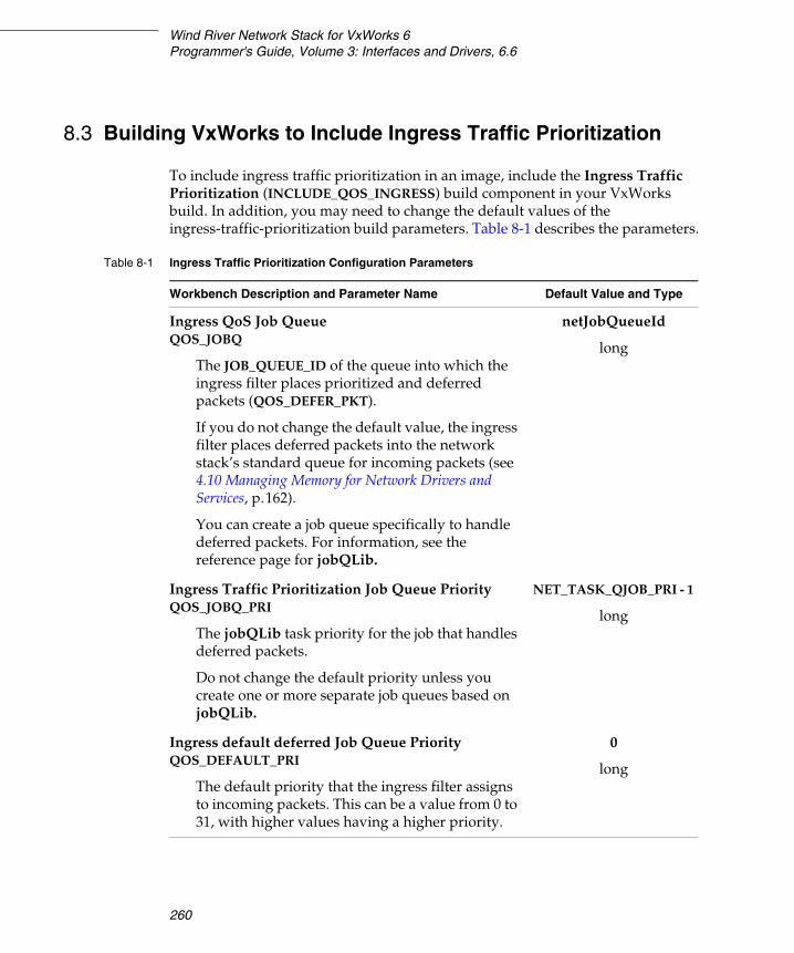
Wind River Network Stack for VxWorks 6Programmer's Guide, Volume 3: Interfaces and Drivers, 6.6
260
8.3 Building VxWorks to Include Ingress Traffic Prioritization
To include ingress traffic prioritization in an image, include the Ingress Traffic Prioritization (INCLUDE_QOS_INGRESS) build component in your VxWorks build. In addition, you may need to change the default values of the ingress-traffic-prioritization build parameters. Table 8-1 describes the parameters.
Table 8-1 Ingress Traffic Prioritization Configuration Parameters
Workbench Description and Parameter Name Default Value and Type
Ingress QoS Job QueueQOS_JOBQ
The JOB_QUEUE_ID of the queue into which the ingress filter places prioritized and deferred packets (QOS_DEFER_PKT).
If you do not change the default value, the ingress filter places deferred packets into the network stack’s standard queue for incoming packets (see 4.10 Managing Memory for Network Drivers and Services, p.162).
You can create a job queue specifically to handle deferred packets. For information, see the reference page for jobQLib.
netJobQueueId
long
Ingress Traffic Prioritization Job Queue PriorityQOS_JOBQ_PRI
The jobQLib task priority for the job that handles deferred packets.
Do not change the default priority unless you create one or more separate job queues based on jobQLib.
NET_TASK_QJOB_PRI - 1
long
Ingress default deferred Job Queue PriorityQOS_DEFAULT_PRI
The default priority that the ingress filter assigns to incoming packets. This can be a value from 0 to 31, with higher values having a higher priority.
0
long
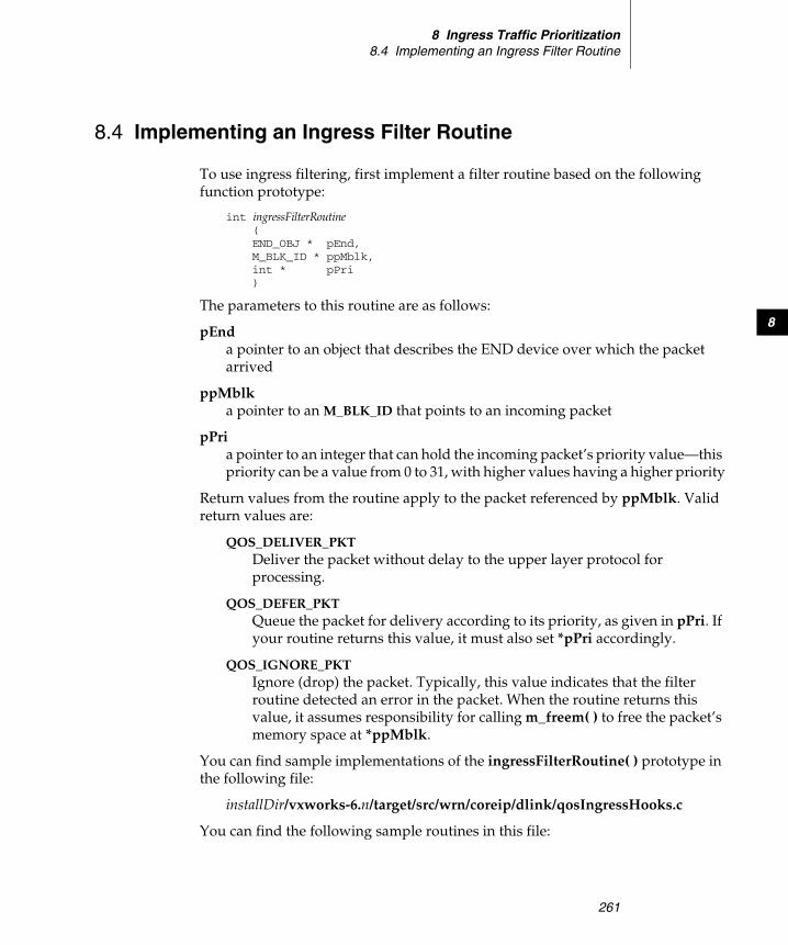
8 Ingress Traffic Prioritization8.4 Implementing an Ingress Filter Routine
261
8
8.4 Implementing an Ingress Filter Routine
To use ingress filtering, first implement a filter routine based on the following function prototype:
int ingressFilterRoutine (END_OBJ * pEnd,M_BLK_ID * ppMblk,int * pPri )
The parameters to this routine are as follows:
pEnd a pointer to an object that describes the END device over which the packet arrived
ppMblk a pointer to an M_BLK_ID that points to an incoming packet
pPri a pointer to an integer that can hold the incoming packet’s priority value—this priority can be a value from 0 to 31, with higher values having a higher priority
Return values from the routine apply to the packet referenced by ppMblk. Valid return values are:
QOS_DELIVER_PKT Deliver the packet without delay to the upper layer protocol for processing.
QOS_DEFER_PKT Queue the packet for delivery according to its priority, as given in pPri. If your routine returns this value, it must also set *pPri accordingly.
QOS_IGNORE_PKT Ignore (drop) the packet. Typically, this value indicates that the filter routine detected an error in the packet. When the routine returns this value, it assumes responsibility for calling m_freem( ) to free the packet’s memory space at *ppMblk.
You can find sample implementations of the ingressFilterRoutine( ) prototype in the following file:
installDir/vxworks-6.n/target/src/wrn/coreip/dlink/qosIngressHooks.c
You can find the following sample routines in this file:

Wind River Network Stack for VxWorks 6Programmer's Guide, Volume 3: Interfaces and Drivers, 6.6
262
etherQosHook( ) Assigns priorities to Ethernet packets based on the protocol specified in the Ethernet header’s type field.
vlanQosHook( ) Assigns priorities based on the priority field in the VLAN header.
ipProtoQosHook( ) Assigns priorities based on the transport protocol and port-number fields in the packet’s header.
dscpQosHook( ) Assigns priorities based on the packet’s differentiated-services code-point (DSCP) field.
8.4.1 Registering an Ingress Filter Routine
To register an ingress filter routine for an interface, call the qosIngressHookSet( ) routine.
The syntax for qosIngressHookSet( ) is:
STATUS qosIngressHookSet ( int unit,char * ifname,QOS_ING_HOOK hookRtn )
The parameters to this routine are as follows:
unit the unit number of the interface, for example, 0
ifname the name of the interface, for example, "fei"
hookRtn a pointer to the ingress-filter routine that you are registering
Deactivating Ingress Traffic Prioritization on an Interface
To deregister an ingress filter routine from an interface, which deactivates ingress traffic prioritization on an interface, call qosIngressHookSet( ) with hookRtn set to NULL.

263
AMUX Routines and
Data Structures
A.1 Introduction 263
A.2 MUX Routines 263
A.3 Data Structures 287
A.1 Introduction
This appendix describes the routines and data structures that comprise the MUX API.
A.2 MUX Routines
This section provides descriptions of the following routines, as illustrated in Figure A-1:

Wind River Network Stack for VxWorks 6Programmer's Guide, Volume 3: Interfaces and Drivers, 6.6
264
Figure A-1 MUX API Calls, Illustrated
END/NPT MUX
service/protocol
driver
muxAddressForm
muxDevLoadxLoad
application
xFormAddress
muxDevExists
muxDevStartxStart
muxDevStopxStop
muxDevUnloadxUnload
xShutdownRtn
muxError xStackErrorRtn
muxIfFuncAdd
END driver
muxMCastAddrAdd
muxIoctlxIoctl
muxTkDrvCheck
xMCastAddrAdd
mux[Tk]BindxEndBind
muxPollReceivexPollRcv
muxPollSendxPollSend
mux[Tk]Receive xStackRcvRtn
mux[Tk]SendxSend
muxUnbind
muxTxRestart xStackRestartRtn
muxIfFuncDel
muxIfFuncGet
xMCastAddrDel
xMCastAddrGet
muxMCastAddrDel
muxMCastAddrGet
receiveRtn
xAttach
muxPacketDataGet
xPacketDataGet muxPacketAddrGet
xAddrGet
muxTkCookieGet
muxLinkHeaderCreate
A MUX Routines and Data StructuresA.2 MUX Routines
265
A
■ endFindByName( ), p.265 ■ muxAddressForm( ), p.266 and muxLinkHeaderCreate( ), p.267■ muxDevExists( ), p.267 ■ muxDevLoad( ), p.268 ■ muxDevStart( ), p.268 ■ muxDevStop( ), p.269 ■ muxDevUnload( ), p.269 ■ muxError( ), p.270 ■ muxIfFuncAdd( ), p.270 ■ muxIfFuncDel( ), p.271 ■ muxIfFuncGet( ), p.271 ■ muxIoctl( ), p.272 ■ muxMCastAddrAdd( ), p.272 ■ muxMCastAddrDel( ), p.273 ■ muxMCastAddrGet( ), p.273 ■ muxPacketAddrGet( ), p.274■ muxPacketDataGet( ), p.274■ muxShow( ), p.275■ muxTkBind( ), p.275 and muxBind( ), p.277 ■ muxTkCookieGet( ), p.279 ■ muxTkDrvCheck( ), p.279 ■ muxTkPollReceive( ), p.280 ■ muxTkPollSend( ), p.281 ■ muxTkReceive( ), p.282 and muxReceive( ), p.281■ muxTkSend( ), p.284 and muxSend( ), p.283■ muxTxRestart( ), p.285 ■ muxUnbind( ), p.285■ muxAddrResFuncAdd( ), p.286 – deprecated; use muxIfFuncAdd( ) ■ muxAddrResFuncDel( ), p.286 – deprecated; use muxIfFuncDel( ) ■ muxAddrResFuncGet( ), p.287 – deprecated; use muxIfFuncGet( )
A.2.1 endFindByName( )
Call endFindByName( ) to retrieve the DRV_CTRL object that represents a device (cast in the form of its END_OBJ superclass) based on the device’s unit number and root name.
END_OBJ * endFindByName (char * pName, int unit);
For instance, the following call will retrieve the DRV_CTRL object for motfec0:
DRV_CTRL * pDrvCtrl = (DRV_CTRL *) endFindByName("motfec", 0);

Wind River Network Stack for VxWorks 6Programmer's Guide, Volume 3: Interfaces and Drivers, 6.6
266
If the routine is unable to find any device that matches this unit number and root name, it returns NULL. If it understands the root name, but there is no unit under that root name that matches the unit number, the routine also sets errno to S_muxLib_NO_DEVICE.
A.2.2 muxAddressForm( )
Call muxAddressForm( ) to add a link header to a packet. A network service needs this routine when it works with ENDs, which are frame-oriented, but not with NPT drivers, which are packet oriented.
Before calling muxAddressForm( ), set the mBlkHdr.mData members of the pSrcAddr and pDstAddr M_BLKs to point to buffers containing the source and destination link-level addresses (respectively). Also, set pDstAddr->mBlkHdr.reserved to the network service type, stored in network byte order.
With this input, muxAddressForm( ) will attempt to prefix a link header to the packet pMblk. If sufficient leading space is available in the first tuple’s cluster, and that cluster is unshared, muxAddressForm( ) will write the link header in the available leading space; otherwise, it will attempt to allocate, from the network pool pointed to by the global _pNetDpool, a new tuple to hold the link header, and prefix this tuple to the existing chain. muxAddressForm( ) returns a pointer to the first M_BLK of the resulting chain; this would just be pMblk in case the existing first cluster had enough available unshared leading space to hold the link header. In the case that a new tuple is required but cannot be allocated, muxAddressForm( ) frees the original packet and returns NULL.
M_BLK_ID muxAddressForm(void * pCookie, /* the cookie returned by muxBind() */M_BLK_ID pMblk, /* pointer to the packet being reformed */
NOTE: The current Wind River IP stack does not use muxAddressForm( ). By default, _pNetDpool is NULL and any attempt by muxAddressForm( ) to allocate a new tuple will fail. If you add the component INCLUDE_NET_POOL to the VxWorks image, the legacy stack network data pool and system pool will be available, and _pNetDpool will point to the stack data pool. muxAddressForm( ) uses M_PREPEND( ) to allocate 128-byte tuples when it cannot prepend the link header in the existing leading cluster space. It may be necessary for some applications to configure the legacy stack data pool to include additional 128-byte clusters, by increasing the parameter NUM_DAT_128 above its default of 128 clusters.
A MUX Routines and Data StructuresA.2 MUX Routines
267
A
M_BLK_ID pSrcAddr, /* pointer to the M_BLK with the source address */M_BLK_ID pDstAddr /* pointer to the M_BLK with the dest address */)
A.2.3 muxLinkHeaderCreate( )
The muxLinkHeaderCreate( ) routine, like muxAddressForm( ), adds a link layer header to a packet.
This routine constructs a link-level header using the source address of the device indicated by the pCookie argument as returned from the muxBind( ) routine.
The pDstAddr argument points to an M_BLK buffer containing the link-level destination address. Alternatively, the bcastFlag argument, if TRUE, indicates that the routine should use the link-level broadcast address, if available for the device. Although other information contained in the pDstAddr argument must be accurate, the address data itself is ignored in that case.
The pPacket argument contains the contents of the resulting link-level frame. This routine prepends the new link-level header to the initial M_BLK in that network packet if space is available or allocates a new tuple and prepends it to the M_BLK chain.
When construction of the header is complete, this routine returns an M_BLK_ID that points to the initial M_BLK in the assembled link-level frame.
If this routine returns NULL, it frees the input M_BLK pPacket.
M_BLK_ID muxLinkHeaderCreate(void * pCookie, /* the cookie returned by muxBind() */M_BLK_ID pPacket, /* pointer to the packet being reformed */M_BLK_ID pSrcAddr, /* pointer to the M_BLK with the source address */M_BLK_ID pDstAddr, /* pointer to the M_BLK with the dest address */BOOL bcastFlag /* use broadcast destination (if available)? */)
A.2.4 muxDevExists( )
Call muxDevExists( ) to test whether a given device has already been loaded into the network stack. As input, it expects the name and unit number of the device to be tested.
BOOL muxDevExists(char * pName, /* string containing a device name (ln, ei, ...)*/int unit /* unit number */

Wind River Network Stack for VxWorks 6Programmer's Guide, Volume 3: Interfaces and Drivers, 6.6
268
)
This routine returns TRUE if the device has already been loaded into the network stack, or FALSE otherwise. Note that a TRUE return from this routine does not guarantee that the device will still be loaded at a later time.
A.2.5 muxDevLoad( )
Call muxDevLoad( ) to load a network driver into the MUX. muxDevLoad( ) calls the driver’s xLoad( ) routine. After the device loads, you can call muxDevStart( ) to start the device.
muxDevLoad( ) passes the contents of the pInitString string into the driver’s xLoad( ) routine, prepended with “unitNumber:”
Some drivers require that the BSP provide additional information to the driver’s load routine via the pBSP argument to muxDevLoad( ) (or the device’s xLoad( ) routine). Check the driver’s reference manual entry to see if this is the case. If so, the endDevTbl[ ] entry for the device unit in the BSP’s configNet.c file may provide this value, or if the BSP provides a wrapper load routine, that routine may pass a pBSP argument directly to the driver’s xLoad( ) routine. VxBus drivers always pass the device instance’s VXB_DEVICE_ID in the pBSP parameter.
void * muxDevLoad(int unit, /* unit number of device */END_OBJ * (* endLoad)(char *, void *), /* driver's load routine */char * pInitString, /* init string for driver */BOOL loaning, /* unused */void * pBSP /* BSP-specific */)
This routine returns a cookie that identifies the device and that you can pass to muxDevStart( ), or returns NULL if the routine could not load the device, in which case it sets errno to S_muxLib_LOAD_FAILED.
A.2.6 muxDevStart( )
Use muxDevStart( ) to start a device after you successfully load the device by calling muxDevLoad( ). muxDevStart( ) activates a device by calling the driver’s xStart( ) routine, enabling reception and transmission on the device.
STATUS muxDevStart(void * pDevCookie /* the cookie returned from muxDevLoad() */)

A MUX Routines and Data StructuresA.2 MUX Routines
269
A
The muxDevStart( ) routine returns OK on success, ERROR if the driver’s xStart( ) routine fails, or ENETDOWN if pDevCookie does not represent a valid device (in which case it will set errno to S_muxLib_NO_DEVICE).
A.2.7 muxDevStop( )
Call muxDevStop( ) to stop a device. muxDevStop( ) calls the driver’s xStop( ) routine.
STATUS muxDevStop(void * pCookie /* the cookie returned from muxDevLoad() */)
The muxDevStop( ) routine returns OK on success, ERROR if the driver’s xStop( ) routine fails, or ENETDOWN if pCookie does not represent a valid device (in which case it will set errno to S_muxLib_NO_DEVICE).
A.2.8 muxDevUnload( )
Call muxDevUnload( ) to unload a device from the MUX.
To notify services that it is unloading a device, muxDevUnload( ) calls the stackShutdownRtn( ) routine implemented by each service bound to the device (these stackShutdownRtn( ) routines in turn call muxUnbind( ) to detach from the device).
To free device-internal resources, muxDevUnload( ) calls the driver’s xUnload( ) routine.
STATUS muxDevUnload(char * pName, /* the name of the device, for example, ln or ei */int unit /* the unit number */)
This routine returns OK on success, ERROR if the device could not be found (in which case it sets errno to S_muxLib_NO_DEVICE), or the error returned from the device’s xUnload( ) routine if that routine fails (in which case it sets errno to S_muxLib_UNLOAD_FAILED).
Wind River Network Stack for VxWorks 6Programmer's Guide, Volume 3: Interfaces and Drivers, 6.6
270
A.2.9 muxError( )
Drivers call muxError( ) to report an error (or sometimes a condition other than an error) to a network service that is bound to it through the MUX. You can find predefined errors in end.h. A driver passes this routine two arguments: a pointer to the END object that identifies the device that is issuing the error and a pointer to an END_ERR structure that the driver has allocated and filled, and that the driver maintains ownership of across the call to muxError( ). See A.3.5 END_ERR, p.293, for a description of this structure.
void muxError(void * pCookie, /* END_OBJ pinter cast to a void pointer */END_ERR * pError /* error structure */}
If pCookie is NULL this routine sets errno to S_muxLib_NO_DEVICE.
A.2.10 muxIfFuncAdd( )
Call muxIfFuncAdd( ) to provide the MUX with pointers to certain routines that depend both upon a protocol’s network service type and upon a MIB2 interface type code. You can use muxIfFuncAdd( ) to specify up to three different such routines:
■ an address resolution routine ■ a multicasting address resolution routine ■ an output routine
STATUS muxIfFuncAdd(long ifType, /* Media interface type, from m2Lib.h */long protocol, /* Service type, for instance from RFC 1700 */int funcType, /* type of function being added */FUNCPTR ifFunc /* Function to call. */)
ifType A media interface or network driver type, such as can be found in m2Lib.h. The implementation restricts interface types to the range {0 < ifType <= MUX_MAX_IFTYPE}, where MUX_MAX_IFTYPE is defined in muxLib.h.
protocol A network service or protocol type, such as can be found in RFC 1700 (look for the values in the table under “ETHER TYPES”). For example, use 2048 (0x800
A MUX Routines and Data StructuresA.2 MUX Routines
271
A
hexadecimal) to identify IPv4. Not all relevant network service types are listed in RFC 1700. For instance, IPv6’s network service type is 0x86DD, defined in RFC 2464. The most comprehensive official list seems to be http://standards.ieee.org/regauth/ethertype/eth.txt although it lacks some protocol identifications.
funcType Set this to one of the following three values to indicate the variety of routine you are registering:
– ADDR_RES_FUNC – an address resolution routine– IF_OUTPUT_FUNC – an output routine– MULTI_ADDR_RES_FUNC – a multicasting address resolution routine
ifFunc A pointer to a routine for this combination of driver type and service type.
If ifType is outside of the supported range, if there is insufficient memory to complete the operation, or if this variety of service routine has already been registered for this ifType/service variety, muxIfFuncAdd( ) returns ERROR. Otherwise it returns OK.
A.2.11 muxIfFuncDel( )
Call muxIfFuncDel( ) to undo the assignment of a service routine to an interface-type/protocol combination.
STATUS muxIfFuncDel(long ifType, /* media interface type from m2Lib.h */long protocol, /* protocol type, for instance from RFC 1700 */int funcType /* type of function to delete. */)
Valid values for funcType are ADDR_RES_FUNC, IF_OUTPUT_FUNC, and MULTI_ADDR_RES_FUNC. For more information on these routine types, see A.2.10 muxIfFuncAdd( ), p.270.
The muxIfFuncDel( ) routine returns OK on success, or ERROR if the request fails.
A.2.12 muxIfFuncGet( )
Call muxIfFuncGet( ) to retrieve a pointer to a service routine associated with an interface type/network service type combination by an earlier call to muxIfFuncAdd( ).
Wind River Network Stack for VxWorks 6Programmer's Guide, Volume 3: Interfaces and Drivers, 6.6
272
FUNCPTR muxIfFuncGet(long ifType, /* media interface type from m2Lib.h */long protocol, /* protocol type, for instance from RFC 1700 */int funcType /* type of function to get */)
Valid values for funcType are ADDR_RES_FUNC, IF_OUTPUT_FUNC, and MULTI_ADDR_RES_FUNC. For more information on these routine types, see A.2.10 muxIfFuncAdd( ), p.270.
This routine returns a pointer to the requested routine, or NULL if no routine was registered by a previous call to muxIfFuncAdd( ) for the service or if ifType is invalid.
A.2.13 muxIoctl( )
Call muxIoctl( ) to access the ioctl services of a network interface loaded into the MUX. Typical uses of muxIoctl( ) include commands to fetch or modify device flags, read or modify hardware offload capability settings, poll device statistics, add or remove multicast addresses, fetch or modify the unicast station address, or fetch the current link state or force the current link mode. In most cases, muxIoctl( ) calls the network driver’s xIoctl( ) routine.
STATUS muxIoctl(void * pCookie, /* returned by muxTkBind() */int cmd, /* ioctl command */caddr_t data /* data needed to carry out the command */)
This routine returns OK if successful, ERROR (or some other error value returned by the device’s xIoctl( ) routine) if the device was unable to successfully complete the command, or ENETDOWN if pCookie does not represent a valid device (in which case it sets errno to S_muxLib_NO_DEVICE).
A.2.14 muxMCastAddrAdd( )
Call muxMCastAddrAdd( ) to add an address to the table of link layer multicast addresses that a device maintains. It expects two arguments: the cookie that muxTkBind( ) returned that identifies the device, and a pointer to a buffer containing the address to be added. The length of the link-layer multicast address is presumed known to both the driver and the protocol; for example, it is 6 bytes for ethernet devices.
A MUX Routines and Data StructuresA.2 MUX Routines
273
A
STATUS muxMCastAddrAdd(void * pCookie, /* returned by muxTkBind() */char * pAddress /* address to add to the table */)
This routine returns OK if successful, ERROR (or some other error value returned by the device’s xMCastAddrAdd( ) routine) if the device was unable to successfully add the address, or ENETDOWN if pCookie does not represent a valid device (in which case it sets errno to S_muxLib_NO_DEVICE).
A.2.15 muxMCastAddrDel( )
Call muxMCastAddrDel( ) to remove an address from the table of multicast addresses that the device maintains. It expects two arguments: the cookie that muxTkBind( ) returned that identifies the device, and a pointer to a buffer containing the link layer address to be removed. Note that the driver (often with the help of etherMultiLib) maintains a reference count for each multicast address added, and the driver only reconfigures the device to stop receiving frames destined for a multicast address in the table when the reference count for that address decreases to zero.
STATUS muxMCastAddrDel(void * pCookie, /* returned by muxTkBind() */char * pAddress /* address to delete from the table */)
This routine returns OK if successful. It returns ERROR (or some other error value returned by the device’s xMCastAddrDel( ) routine) if the device was unable to successfully remove the address. The routine returns ENETDOWN if pCookie does not represent a valid device (in which case it sets errno to S_muxLib_NO_DEVICE).
A.2.16 muxMCastAddrGet( )
Call muxMCastAddrGet( ) to retrieve the list of multicast addresses that the device maintains. It expects two arguments: the cookie that muxTkBind( ) returned that identifies the device, and a pointer to a MULTI_TABLE structure (see A.3.16 MULTI_TABLE, p.307). This MULTI_TABLE structure contains the address and length of a buffer which the driver’s xMCastAddrGet( ) routine will fill with the addresses currently in its multicast table. The driver decreases the buffer length field in the MULTI_TABLE to the actual number of bytes of multicast address information that the driver wrote into the buffer.
Wind River Network Stack for VxWorks 6Programmer's Guide, Volume 3: Interfaces and Drivers, 6.6
274
int muxMCastAddrGet(void * pCookie, /* returned by muxTkBind() */MULTI_TABLE * pTable /* structure that will hold retrieved table */)
This routine returns OK if successful, ERROR (or some other error value returned by the device’s xMCastAddrGet( ) routine) if the device was unable to successfully supply the list, or ENETDOWN if pCookie does not represent a valid device (in which case it sets errno to S_muxLib_NO_DEVICE).
A.2.17 muxPacketAddrGet( )
The muxPacketAddrGet( ) routine retrieves the addressing information from a packet. As input it takes pCookie (the binding instance cookie that muxBind( ) returned), pMblk (referencing the M_BLK that describes a packet), and four additional M_BLK_IDs into which the routine can write addressing information, as follows:
■ pSrcAddr – the immediate source address of the packet■ pDstAddr – the immediate destination address of the packet■ pESrcAddr – the ultimate source address of the packet■ pEDstAddr – the ultimate destination address of the packet
You may pass in NULL for any of these four parameters for which you do not need the associated information.
STATUS muxPacketAddrGet(void * pCookie, /* service/device binding from muxBind() */M_BLK_ID pMblk, /* structure to contain packet */M_BLK_ID pSrcAddr, /* structure containing source address */M_BLK_ID pDstAddr, /* structure containing destination address */M_BLK_ID pESrcAddr, /* structure containing the end source */M_BLK_ID pEDstAddr /* structure containing the end destination */)
This routine relies on the driver’s xAddrGet( ) routine, which only END-style drivers implement (see xAddrGet( ), p.157). muxPacketAddrGet( ) will return ERROR if pCookie refers to a driver that does not implement the xAddrGet( ) routine. Otherwise, it will return the return value from xAddrGet( ).
A.2.18 muxPacketDataGet( )
Call muxPacketDataGet( ) to parse the link level header at the start of a packet. The routine does not modify the packet, but fills out the specified LL_HDR_INFO

A MUX Routines and Data StructuresA.2 MUX Routines
275
A
structure with information about the link level header (see A.3.11 LL_HDR_INFO, p.302). Among other items, this provides the length of the link header and the network service type of the packet. This routine copies this link-level header information from the packet referenced in pMblk into the LL_HDR_INFO structure referenced in pLinkHdrInfo.
STATUS muxPacketDataGet(void * pCookie, /* service/device binding from muxBind() */M_BLK_ID pMblk, /* returns the packet data */LL_HDR_INFO * pLinkHdrInfo /* returns the packet header information */)
If the device that is bound in the interface represented by pCookie does not implement an xPacketDataGet( ) routine, this routine returns ERROR. If pCookie does not represent a valid device at all, this routine returns ERROR and sets errno to S_muxLib_NO_DEVICE. Otherwise, this routine returns the return value from the driver’s xPacketDataGet( ) routine.
A.2.19 muxShow( )
Call the muxShow( ) routine to display configuration information about the devices that are registered with the MUX.
If you pass a NULL pDevName argument to muxShow( ), the routine will report on the entire list of existing devices and the services that are bound to them. You can set pDevName to the root name of the device, and unit to the unit number if you want a report about only a specific device.
void muxShow(char * pDevName, /* pointer to device name, or NULL for all */int unit /* unit number for a single device */)
A.2.20 muxTkBind( )
Call muxTkBind( ) to bind a network service to a network interface. Before the network service can send and receive packets from the network, it must bind to one or more network drivers through which it will send and receive packets. To specify these network drivers and bind to them, call muxTkBind( ).
In the call to muxTkBind( ) provide the following information:
■ the network driver to bind to (name and unit number)

Wind River Network Stack for VxWorks 6Programmer's Guide, Volume 3: Interfaces and Drivers, 6.6
276
■ a network service type, for instance based on RFC 1700
■ optional data structures used to exchange information with the driver (typically used when a network service is designed to work with a particular network driver)
■ a set of callback routines used by the MUX (see Table A-1)
■ a key or private data structure that the MUX will pass back when it invokes these callbacks, and that identifies the bound interface
These callback routines are listed in Table A-1 and are described at greater length in 5.3.1 Service Routines Registered Using mux[Tk]Bind( ), p.186.
Two additional arguments (pNetSvcInfo and pNetDrvInfo) are rarely used. They allow the sublayer to exchange additional information with a network driver at bind time, depending on requirements specific to the particular service and driver, by means of a call to the device’s xEndBind( ) routine (see xEndBind( ), p.158). These additional arguments may be helpful to those network services and network driver types that are tightly coupled. Wind River has established no conventions regarding the use of these arguments. Pass NULL for both if you do not use them.
The muxTkBind( ) routine is declared as follows:
void * muxTkBind(char * pName, /* interface name, for example: ln, ei */int unit, /* unit number */FUNCPTR stackRcvRtn, /* data receive callback */FUNCPTR stackShutdownRtn, /* shutdown callback */FUNCPTR stackTxRestartRtn, /* restart after suspend callback */VOIDFUNCPTR stackErrorRtn, /* message/error callback */long type, /* from RFC 1700 or otherwise-defined */char * pProtoName, /* string name of service */void * pNetCallbackId, /* returned to svc sublayer during recv *void * pNetSvcInfo, /* ref to netSrvInfo structure */void * pNetDrvInfo /* ref to netDrvInfo structure */
Table A-1 Network Service Callback Routines
Callback Routine Description
stackRcvRtn( ) Receive data from the MUX.
stackErrorRtn( ) Receive an error notification from the MUX.
stackShutdownRtn( ) Shut down the network service.
stackRestartRtn( ) Restart a suspended network service.

A MUX Routines and Data StructuresA.2 MUX Routines
277
A
)
The pNetCallbackId argument is an opaque “cookie” value that the MUX passes when it calls the callback routines, to identify the involved END device to the service.
The pProtoName argument is a NUL-terminated string describing the service, and type is the network service type. The MUX uses the network service type to prioritize the services, and to determine which services see which packets (see The Bind Phase, p.181).
The muxTkBind( ) routine returns a cookie that uniquely represents the binding instance and identifies that binding instance in subsequent calls that the service makes to the MUX. A return value of NULL indicates that the bind failed. In such a case the following errno values may help diagnose the problem:
EINVAL You attempted to use muxBind( ) rather than muxTkBind( ) to bind a service to an NPT device.
S_muxLib_ALLOC_FAILED muxTkBind( ) could not allocate enough memory to complete the binding.
S_muxLib_ALREADY_BOUND You are trying to bind an output protocol to a device that already has an output protocol attached to it, or are trying to bind a normal-typed network service to a device that already has a service of the same type bound.
S_muxLib_NO_DEVICE There is no device matching pName and unit.
A.2.21 muxBind( )
Call muxBind( ) to bind a network service to a network interface that is governed by an END. You can also use muxTkBind( ) to bind to either an END or an NPT driver, but you cannot use muxBind( ) to bind to an NPT driver. Calling muxBind( ) instead of muxTkBind( ) for END interfaces may be more efficient.
Before the network service can send and receive packets from the network, it must bind to one or more drivers through which it will send and receive packets. In the call to muxBind( ) provide the following information:
■ the END device to bind to (name and unit number)
■ a network service type, for instance based on RFC 1700

Wind River Network Stack for VxWorks 6Programmer's Guide, Volume 3: Interfaces and Drivers, 6.6
278
■ a set of callback routines used by the MUX (see Table A-1)
■ a key or private data structure that the MUX will pass back when it invokes these callbacks, and that identifies the bound interface
These callback routines are listed in Table A-1 and are described at greater length in 5.3.1 Service Routines Registered Using mux[Tk]Bind( ), p.186.
As part of the bind phase, the network service typically retrieves the address resolution and mapping routines for each network interface that it is binding to, and stores them in a private data structure that the service allocates.
The muxBind( ) routine is defined as follows:
void * muxBind ( char * pName, /* interface name, for example, ln, ei,... */ int unit, /* unit number */ BOOL (*stackRcvRtn) (void*, long, M_BLK_ID, LL_HDR_INFO *, void*),
/* receive function to be called. */ STATUS (*stackShutdownRtn) (void*, void*),
/* routine to call to shutdown the stack */ STATUS (*stackTxRestartRtn) (void*, void*),
/* routine to tell the stack it can transmit */ void (*stackErrorRtn) (END_OBJ*, END_ERR*, void*),
/* routine to call on an error. */ long type, /* protocol type from RFC1700 and many */
/* other sources (for example, 0x800 is IP) */ char * pProtoName, /* string name for protocol */ void * pSpare /* per protocol spare pointer */ )
The pSpare argument is an opaque “cookie” value that the MUX passes when it calls the callback routines, to identify the involved END device to the service.
The pProtoName argument is a NULL-terminated string describing the service, and type is the network service type. The MUX uses the network service type to prioritize the services, and to determine which services see which packets (see The
Table A-2 Network Service Callback Routines
Callback Routine Description
stackRcvRtn( ) Receive data from the MUX.
stackErrorRtn( ) Receive an error notification from the MUX.
stackShutdownRtn( ) Shut down the network service.
stackRestartRtn( ) Restart a suspended network service.
A MUX Routines and Data StructuresA.2 MUX Routines
279
A
Bind Phase, p.181). The muxBind( ) routine returns a cookie that uniquely represents the binding instance and identifies that binding instance in subsequent calls that the service makes to the MUX. A return value of NULL indicates that the bind failed. In such a case the following errno values may help diagnose the problem:
EINVAL You attempted to use muxBind( ) to bind a service to an NPT device.
S_muxLib_ALLOC_FAILED muxBind( ) could not allocate enough memory to complete the binding.
S_muxLib_ALREADY_BOUND You are trying to bind an output protocol to a device that already has an output protocol attached to it, or attempted to bind a normal-typed protocol when a protocol of the same network service type is already bound.
S_muxLib_NO_DEVICE There is no device matching pName and unit.
A.2.22 muxTkCookieGet( )
Call this routine to retrieve a pseudo-“cookie” corresponding to a particular device. You can use this routine to get a cookie for a device without binding to that device, and you can then use this cookie to refer to the device in various MUX calls (except, of course, muxUnbind( )).
If there is no such device, this routine returns NULL, otherwise it returns a device “cookie.”
void * muxTkCookieGet(char * pName, /* Device root name, for instance "motfec" */int unit /* Device unit number, for instance 0 */)
A.2.23 muxTkDrvCheck( )
A network service sublayer calls muxTkDrvCheck( ) to determine whether a particular driver is an NPT driver. Note that the pDevName argument is the root device name, without the unit number, for example "gei" rather than "gei0".

Wind River Network Stack for VxWorks 6Programmer's Guide, Volume 3: Interfaces and Drivers, 6.6
280
int muxTkDrvCheck(char * pDevName /* the root name of the driver being checked */)
This routine returns 1 (one) if that device is an NPT driver, 0 (zero) otherwise, and ERROR (-1) if the routine could not find the specified device.
A.2.24 muxTkPollReceive( )
A network service sublayer calls muxTkPollReceive( ) to poll a device for incoming data. If no data is available at the time of the call, muxTkPollReceive( ) returns EAGAIN. If not NULL, the pSpare argument points to a buffer where an NPT driver may return additional driver-specific data (however, conventions for the use of this parameter are not established, and Wind River recommends that the caller pass NULL for pSpare). In the case of an END, pSpare will always point to NULL when the muxTkPollReceive( ) call returns successfully.
STATUS muxTkPollReceive(void * pCookie, /* returned by muxTkBind() */M_BLK_ID pNBuff, /* a vector of buffers passed to us */void * pSpare /* a reference to spare data is returned here */)
This routine returns OK on success, EAGAIN if the device does not have a packet available, ENETDOWN if pCookie does not represent a valid device (in which case it sets errno to S_muxLib_NO_DEVICE), or ERROR or an error value specific to the driver’s xPollRcv( ) routine if the driver encounters an error.
NOTE: muxTkDrvCheck( ) uses an EIOCGNPT ioctl to ask the driver whether it is an NPT. An NPT driver returns a 1 (one) in response to an EIOCGNPT ioctl.
NOTE: This routine replaces muxPollReceive( ), which is deprecated.
NOTE: Only use polled mode for debugging. For details, see 4.3.3 Polled Mode – For Debugging Only, p.92.

A MUX Routines and Data StructuresA.2 MUX Routines
281
A
A.2.25 muxTkPollSend( )
Call muxTkPollSend( ) to transmit packets when a driver is in polled-mode. This is the polled-mode equivalent to the interrupt-mode muxTkSend( ). When calling muxTkPollSend( ) with a non-NULL pDstAddr argument, the driver does not need to call muxAddressForm( ) to complete the packet. Like muxTkSend( ), this routine expects as arguments a cookie identifying the device and a pointer to the M_BLK chain containing the data.
STATUS muxTkPollSend(void * pCookie, /* returned by muxTkBind()*/M_BLK_ID pNBuff, /* data to be sent */char * dstMacAddr, /* destination MAC address */USHORT netType, /* network service that is calling us */void * pSpareData /* spare data passed to driver on each send */)
This routine returns OK on success, ENETDOWN if the cookie passed in does not represent a valid device (in which case it sets errno to S_muxLib_NO_DEVICE), or an error value specific to the driver’s xPollSend( ) routine.
A.2.26 muxReceive( )
A driver calls the receiveRtn function pointer in its END_OBJ structure to pass validated packets up to the MUX. For ENDs, this function pointer is usually a reference to muxReceive( ).
The muxReceive( ) routine calls the END’s xPacketDataGet( ) routine to extract the packet data from the frame in the pMblk buffer. Then it forwards the packets to network services that are bound to the device by calling the xStackRcvRtn( ) that the service registered with the MUX.
The routine is defined as:
STATUS muxReceive ( void * pCookie, /* device identifier from driver's load routine */ M_BLK_ID pMblk /* buffer containing received frame */ )
NOTE: This routine replaces muxPollSend( ), which is deprecated.
NOTE: Only use polled mode for debugging. For details, see 4.3.3 Polled Mode – For Debugging Only, p.92.

Wind River Network Stack for VxWorks 6Programmer's Guide, Volume 3: Interfaces and Drivers, 6.6
282
This routine returns OK typically, but during debugging may (if your build was compiled with extra debugging checks) return ERROR if either pMblk or pCookie is NULL.
A.2.27 muxTkReceive( )
A driver calls the receiveRtn function pointer in its END_OBJ structure to pass validated packets up to the MUX. For NPT drivers, this function pointer is usually a reference to muxTkReceive( ).
The muxTkReceive( ) routine forwards the packets to a network service by calling the xStackRcvRtn( ) that the service registered with the MUX.
Arguments to muxTkReceive( ) include:
■ a reference to the END object that describes the interface
■ an M_BLK tuple that contains the frame that the driver received
■ the offset into the frame where the data field (the network service layer header) begins
■ the network service type of the service for which the packet is destined (typically, you find this in the link header of the received frame)
■ a flag (uniPromiscuous) that the driver should set to TRUE if it is in promiscuous mode when it makes this call and it receives a unicast or multicast packet that is not intended for this device (when TRUE the MUX does not hand over the packet to network services other than those that registered with the MUX as of types SNARF or PROMISCUOUS)
Setting uniPromiscuous to TRUE is only an optimization, and the driver should do it only if it has a fast way (such as a bit set by the device in the receive descriptor) to determine that the received packet would not have been received if the device were not in promiscuous mode.
■ a reference to any optional data or information that a network service may expect to accompany the packet (or NULL if no such data is expected)
No Wind River protocols expect such data, and no conventions have been established for this argument’s use.
The MUX strips off the frame header before forwarding the packet to the network service, unless the network service is registered as MUX_PROTO_SNARF or MUX_PROTO_PROMISC, in which case it will receive the complete frame.
The routine is defined as:
A MUX Routines and Data StructuresA.2 MUX Routines
283
A
STATUS muxTkReceive(void * pEndCookie, /* (END_OBJ *) cast to (void *) */M_BLK_ID pMblk, /* the buffer being received */long netSvcOffset, /* offset to network datagram in the packet */long netSvcType, /* network service type */BOOL uniPromiscuous, /* TRUE when driver is in promiscuous mode */void * pSpareData /* out-of-band data */)
This routine returns OK typically, but during debugging may (if your build was compiled with extra debugging checks) return ERROR if either pMblk or pEndCookie is NULL.
A.2.28 muxSend( )
A network service calls muxSend( ) to transmit packets through an END.
STATUS muxSend(void * pCookie, /* returned by muxBind()*/M_BLK_ID pNBuff /* data to be sent */)
To send a packet, the caller must supply:
■ the cookie that it obtained from muxBind( ) that identifies the interface to which it is bound
■ a pointer to the buffer chain (M_BLK chain) containing the packet
The caller must insert the link layer addressing information at the head of this buffer before calling muxSend( ). To do this, call muxAddressForm( ).
The muxSend( ) routine may return END_ERR_BLOCK to indicate that the driver is out of resources for transmitting the packet. In this case only, the caller maintains ownership of the packet. The service sublayer may use this error to establish a flow control mechanism, by waiting to send any more packets until the MUX calls the stackRestartRtn( ) callback routine. At that time, the service can resend the original packet that elicited the END_ERR_BLOCK error, as well as any other packets that may have accumulated in the interim, until all are sent or another END_ERR_BLOCK error occurs. The service is allowed to call muxSend( ) again after an END_ERR_BLOCK return and before its stackRestartRtn( ) has been called, but such sends are likely to return END_ERR_BLOCK again, and so waste cycles polling the device for transmit readiness.
This routine returns OK if successful, or END_ERR_BLOCK if the xSend( ) routine of the driver is temporarily unable to complete the send due to insufficient
Wind River Network Stack for VxWorks 6Programmer's Guide, Volume 3: Interfaces and Drivers, 6.6
284
resources or some other problem. Other return values are unusual: ERROR (or the return value of the driver’s xSend( ) routine) if the driver fails to manipulate or send the packet properly, ERROR if pNBuff is NULL, or ENETDOWN if pCookie does not represent a valid device (in which case it sets errno to S_muxLib_NO_DEVICE). muxSend( ) will always take ownership of the packet unless it returns END_ERR_BLOCK.
A.2.29 muxTkSend( )
A network service calls muxTkSend( ) to transmit packets.
STATUS muxTkSend(void * pCookie, /* returned by muxTkBind()*/M_BLK_ID pNBuff, /* data to be sent */char * dstMacAddr, /* destination MAC address */USHORT netType, /* network service that is calling us */void * pSpareData /* optional spare data passed on each send */)
To send a packet, the caller must supply:
■ the cookie that it obtained from muxTkBind( ) that identifies the interface to which it is bound
■ a pointer to the buffer chain (M_BLK chain) containing the packet
Unless the caller has already added a link header to the packet, it must supply also:
■ the link layer destination address to which the packet should be sent
■ the network service type for the packet
If the packet to be sent already contains a link-level header, the caller passes NULL as the dstMacAddr argument. The service sublayer must form the data that it sends into an M_BLK chain (if it is not already in this form). The caller may need to convert a desired network layer protocol destination address to a link-level destination address, using its own routing and address resolution methods.
The muxTkSend( ) routine may return END_ERR_BLOCK to indicate that the driver is out of resources for transmitting the packet. In this case only, the caller maintains ownership of the packet. The service sublayer may use this error to establish a flow control mechanism, by waiting to send any more packets until the MUX calls the stackRestartRtn( ) callback routine. At that time, the service can resend the original packet that elicited the END_ERR_BLOCK error, as well as any other packets that may have accumulated in the interim, until all are sent or another END_ERR_BLOCK error occurs. The service is allowed to call

A MUX Routines and Data StructuresA.2 MUX Routines
285
A
muxTkSend( ) again after an END_ERR_BLOCK return and before its stackRestartRtn( ) has been called, but such sends are likely to return END_ERR_BLOCK again, and so waste cycles polling the device for transmit readiness.
This routine returns OK if successful, END_ERR_BLOCK if the xSend( ) routine of the driver is temporarily unable to complete the send due to insufficient resources or some other problem. Other return values are unusual: ERROR (or the return value of the driver’s xSend( ) routine) if the driver fails to manipulate or send the packet properly, ERROR if pNBuff is NULL, or ENETDOWN if pCookie does not represent a valid device (in which case it sets errno to S_muxLib_NO_DEVICE). muxTkSend( ) will always take ownership of the packet unless it returns END_ERR_BLOCK.
A.2.30 muxTxRestart( )
When a network driver’s xSend( ) routine returns END_ERR_BLOCK, indicating that it cannot complete a send immediately due to a temporary condition (usually lack of space in its transmit descriptor ring), the driver must guarantee to later call muxTxRestart( ) when the device is again able to send more packets. The muxTxRestart( ) routine notifies all services bound to the device (that provided a stackRestartRtn( ) callback) that they may resume sending to the device (see Figure 4-7). A service may implement transmit flow control by pausing transmission to a device upon receiving an END_ERR_BLOCK return from a mux[Tk]Send( ) call, resuming only when muxTxRestart( ) calls its stackRestartRtn( ) callback. Such a service might never resume transmission if the driver send routine did not call muxTxRestart( ).
void muxTxRestart(void * pCookie /* the device’s (END_OBJ *) cast to a (void *) */)
A.2.31 muxUnbind( )
A network service calls muxUnbind( ) to disconnect from a device. As input, muxUnbind( ) expects the cookie identifying the binding instance that was returned by the service’s earlier call to mux[Tk]Bind( ), as well as the network service type and the stackRcvRtn callback pointer used in the earlier call to mux[Tk]Bind( ).
STATUS muxUnbind(

Wind River Network Stack for VxWorks 6Programmer's Guide, Volume 3: Interfaces and Drivers, 6.6
286
void * pCookie, /* value returned from mux[Tk]Bind() */long type, /* the service type passed in at bind-time */FUNCPTR stackRcvRtn /* pointer to the service receive routine */)
This routine returns OK if the service is successfully unbound; or ERROR otherwise. An ERROR return occurs only if the muxUnbind( ) arguments are invalid, or if more general corruption has occurred in the system.
A.2.32 muxAddrResFuncAdd( )
STATUS muxAddrResFuncAdd(long ifType, /* interface type from m2Lib.h, or driver type */long protocol, /* protocol from RFC 1700, or service type */FUNCPTR addrResFunc /* the routine being added. */){return (muxIfFuncAdd (ifType, protocol, ADDR_RES_FUNC, addrResFunc));}
A.2.33 muxAddrResFuncDel( )
STATUS muxAddrResFuncDel(long ifType, /* ifType of function you want to delete */long protocol, /* protocol from which to delete the function */){return (muxIfFuncDel (ifType, protocol, ADDR_RES_FUNC));}
NOTE: This routine is deprecated. It calls muxIfFuncAdd( ), which you should call directly to add an address resolution routine (see A.2.10 muxIfFuncAdd( ), p.270).
NOTE: This routine is deprecated. It calls muxIfFuncDel( ), which you should call directly to delete an address resolution routine (see A.2.11 muxIfFuncDel( ), p.271).

A MUX Routines and Data StructuresA.3 Data Structures
287
A
A.2.34 muxAddrResFuncGet( )
STATUS muxAddrResFuncGet(long ifType, /* ifType of function you want to delete */long protocol, /* protocol from which to delete the function */){return (muxIfFuncGet (ifType, protocol, ADDR_RES_FUNC));}
A.3 Data Structures
This section describes the following classes and structures:
■ CL_BLK, p.288■ DEV_OBJ, p.289 ■ DRV_CTRL, p.290■ END_CAPABILITIES, p.290■ END_ERR, p.293 ■ END_MEDIA, p.296■ END_MEDIALIST, p.297■ END_OBJ, p.297 ■ END_RCVJOBQ_INFO, p.301■ END_QUERY, p.301■ LL_HDR_INFO, p.302 ■ M_BLK, p.302■ M_BLK_HDR, p.304■ M_LINK, p.305■ M_PKT_HDR, p.306■ MULTI_TABLE, p.307■ NET_FUNCS, p.308
NOTE: This routine is deprecated. It calls muxIfFuncGet( ), which you should call directly to get an address resolution routine (see A.2.12 muxIfFuncGet( ), p.271).

Wind River Network Stack for VxWorks 6Programmer's Guide, Volume 3: Interfaces and Drivers, 6.6
288
A.3.1 CL_BLK
A CL_BLK (also known as a cluster block) structure is shown in Figure A-2.
See 2.3.1 Tuples, p.13 for an in-depth exploration of the M_BLK / CL_BLK / cluster construct.
Multiple M_BLKs may attach to the same CL_BLK/cluster pair. Each time an M_BLK attaches to a CL_BLK/cluster pair, the CL_BLK’s reference count (clRefCnt) is incremented. The M_BLKs may reference overlapping or non-overlapping regions within the cluster, but each code path that uses an M_BLK should treat the associated shared cluster as read-only. When an application that uses an M_BLK frees the tuple (for instance, by calling netMblkClFree( ) or netMblkClChainFree( )), this both frees the M_BLK and decrements the cluster block reference count, and, if the reference count reaches zero, frees the CL_BLK and the cluster.
If a CL_BLK’s pClFreeRtn member is non-NULL when the cluster reference count reaches zero during a tuple or cluster-block free operation, the netBufLib
Figure A-2 A CL_BLK Object
struct clBlk
clSize : UINTclRefCnt : intclFreeArg1 : intclFreeArg2 : intclFreeArg3 : int
the total cluster lengthreference count that determines when the cluster can be freed
arguments to pClFreeRtn( )
(CL_BLK)
pClFreeRtn(...) : int an optional free routine that frees the cluster
pClBuf
union clBlkList(CL_BLK_LIST)
char *pClBlkNext
clNode
struct netPool
pNetPool the network pool from which the CL_BLK was allocated
struct clBlk(CL_BLK)

A MUX Routines and Data StructuresA.3 Data Structures
289
A
back-end code calls the pClFreeRtn function as follows, with the NET_POOL spin lock released:
(*pClBlk->pClFreeRtn) (pClBlk->clFreeArg1, pClBlk->clFreeArg2,pClBlk->clFreeArg3);
The pClFreeRtn routine should do what is necessary to free the cluster; the netBufLib back end code goes on to free the CL_BLK.
On the other hand, if pClFreeRtn is NULL when a cluster reference count reaches zero during a free operation, the cluster is automatically freed to the pool, as appropriate to the particular netBufLib back end in use. (For linkBufPool pools, the whole tuple is returned to the pool at that time.)
Generally, you only need to provide a cluster free routine if the clusters you use do not come from the netBufLib pool that your CL_BLKs come from.
A.3.2 DEV_OBJ
The MUX uses the DEV_OBJ structure to store the name and control structure of a device. The private control structure, held in the pDevice field of this structure, stores information such as memory pool addresses and other essential data. The DEV_OBJ structure is defined in end.h as shown in Figure A-3.
The members of this class are as follows:
name A string that contains the name of the network device.
unit The unit number of the device. Unit numbers start at zero and increase for each device controlled by the same driver.
Figure A-3 The DEV_OBJ Class
DEV_OBJ
name : char[END_NAME_MAX]unit : intdescription : char[END_DESC_MAX]pDevice : void *
Wind River Network Stack for VxWorks 6Programmer's Guide, Volume 3: Interfaces and Drivers, 6.6
290
description A text description of the device driver. For example, the Lance Ethernet driver has a description string of “AMD 7990 Lance Ethernet Enhanced Network Driver.” The muxShow( ) command displays this string.
pDevice Driver load routines call the END_OBJ_INIT( ) macro, implemented by the endObjInit( ) routine in endLib.
endObjInit( ) sets the pDevice member of the DEV_OBJ embedded in the END_OBJ referenced by its first argument to the value of its second argument. When the device is unloaded from the MUX, if the device’s xUnload( ) routine returns OK, muxDevUnload( ) frees the memory pointed to by this member (if non-NULL) to the kernel heap. Usually a network driver passes either a pointer to the END_OBJ or driver control structure itself, or NULL, as the second argument to endObjInit( ), so either a pointer to the END_OBJ or NULL gets stored in this member, and either the END_OBJ, or nothing, gets freed when the driver’s xUnload( ) routine returns OK.
A.3.3 DRV_CTRL
A driver defines its own DRV_CTRL structure, which derives from the END_OBJ structure and contains any additional information that the driver wants to keep track of on a per-device basis. See A.3.8 END_OBJ, p.297. Because the first member of a DRV_CTRL structure conventionally is an END_OBJ structure, the driver can locate its DRV_CTRL structure simply by casting the END_OBJ pointer passed to its NET_FUNCS routines as a DRV_CTRL pointer.
A.3.4 END_CAPABILITIES
A network driver initializes an END_CAPABILITIES object to indicate which of several capabilities the device supports and has enabled. The members of the END_CAPABILITIES object hold the capabilities available, those currently enabled, and the supported CSUM (hardware checksum enabling) flags for receive and transmit.

A MUX Routines and Data StructuresA.3 Data Structures
291
A
The cap_available member reflects the capabilities supported by the driver. The cap_enabled member reflects the capabilities actually enabled. The driver loads the cap_available member with the capabilities supported by the device and initializes the cap_enabled member with the same values. Later, the MUX calls the driver’s xIoctl( ) routine to determine which capabilities the driver supports. The network stack may then change the cap_enabled member to request capabilities that it supports and desires. It is not an error if the stack requests cap_enabled capabilities that the driver does not have available. However, such capabilities are not provided.
The csum_flags_tx and csum_flags_rx members contain translations of cap_available and cap_enabled into CSUM flags. The CSUM flags provide more detailed information about the particular operations supported. CSUM flags are also used on a per-packet basis to pass checksum offload related requests and information between the stack and the network driver. The flags reported by the driver in the csum_flags_tx member of the END_CAPABILITIES object are the only flags that the stack may set in the first M_BLK of a packet to request transmit offload operations from the driver. The flags that the driver sets in csum_flags_rx are currently only of informational use; they are not used by the stack.
A network driver initializes the END_CAPABILITIES object in its xLoad( ) routine. The driver uses the capability flags defined in end.h to initialize the cap_available and cap_enabled fields and the CSUM flags defined in mbuf.h to initialize the csum_flags_tx and csum_flags_rx fields.
For example, if the network stack requests transmit checksum support by setting IFCAP_TXCSUM in cap_enabled and the cap_available field reflects that the driver supports transmit checksumming by also having the IFCAP_TXCSUM bit set, the driver might set the csum_flags_tx field as follows:
(CSUM_IP | CSUM_TCP | CSUM_UDP)
Interface capabilities flags for the cap_available and cap_enabled fields are listed in Table A-3.
Figure A-4 The END_CAPABILITIES Class
END_CAPABILITIES
cap_available : uint32 supported capabilitiesthose supported capabilities that are enabledcapabilities, mapped to CSUM flags, for transmit
cap_enabled : uint32csum_flags_tx : uint32csum_flags_rx : uint32 capabilities, mapped to CSUM flags, for receive

Wind River Network Stack for VxWorks 6Programmer's Guide, Volume 3: Interfaces and Drivers, 6.6
292
Flags indicating hardware checksum support and software checksum requirements are listed in Table A-4.
Table A-3 Interface Capability Flags for cap_available and cap_enabled
Flag Description
IFCAP_RXCSUM Supports IPv4 receive checksum offload
IFCAP_TXCSUM Supports IPv4 transmit checksum offload
IFCAP_VLAN_MTU Supports VLAN-compatible MTU
IFCAP_VLAN_HWTAGGING Supports hardware VLAN tags
IFCAP_JUMBO_MTU Supports 9000 byte MTU
IFCAP_TCPSEG Supports IPv4/TCP segmentation(this capability is not yet available)
IFCAP_IPSEC Supports IPsec(this capability is not yet available)
IFCAP_IPCOMP Supports IPcomp(this capability is not yet available)
IFCAP_CAP0 Vendor specific capability #0
IFCAP_CAP1 Vendor specific capability #1
IFCAP_CAP2 Vendor specific capability #2
Table A-4 Hardware and Software Checksum Support Flags
Flag Description
CSUM_IP Device supports IPv4 header checksum offload
CSUM_TCP Device supports TCP/IPv4 checksum offload
CSUM_UDP Device supports UDP/IPv4 checksum offload
CSUM_IP_FRAGS Device can checksum IP fragments(this capability is not yet available)
CSUM_FRAGMENT Device can fragment IP packets(this capability is not yet available)

A MUX Routines and Data StructuresA.3 Data Structures
293
AThe END_CAPABILITIES class is used by the driver’s interface capabilities set and get ioctls:
■ EIOCSIFCAP – Interface capabilities set ioctl■ EIOCGIFCAP – Interface capabilities get ioctl
A.3.5 END_ERR
Sometimes a driver encounters errors or other events that are of interest to the protocols using that driver. For example, the device’s connection to its link could go down or come back up, or the device might run out of packet buffers during heavy receive load. When such situations arise, the driver should call muxError( ). This routine passes error information up to the MUX, which in turn passes the information on to all services that have registered a routine to receive the information.
Among its input, this routine expects a pointer to an END_ERR structure that the caller has allocated and initialized, and which is declared in end.h as shown in Figure A-5.
CSUM_TCP_SEG Device can segment TCP/IPv4(this capability is not yet available)
CSUM_TCPv6 Device supports TCP/IPv6 checksum offload
CSUM_UDPv6 Device supports UDP/IPv6 checksum offload
CSUM_TCPv6_SEG Device can segment TCP/IPv6(this capability is not yet available)
Table A-4 Hardware and Software Checksum Support Flags (cont’d)
Flag Description
Figure A-5 The END_ERR Class
END_ERR
errCode : INT32 error code (see table)NULL-terminated descriptive error messagepointer to optional user-defined data
pMesg : char *pSpare : void *

Wind River Network Stack for VxWorks 6Programmer's Guide, Volume 3: Interfaces and Drivers, 6.6
294
Values of the errCode member in the range 0..65535 are reserved for system use; you may allocate custom error codes outside of this range. Table A-5 lists currently defined error codes:
Table A-5 END_ERR Error Codes
Error Code Description
END_ERR_INFO This error is informational only.
END_ERR_WARN A non-fatal error has occurred.
END_ERR_RESET An error occurred that forced the device to reset itself, but the device has recovered.
END_ERR_FLAGS The driver has changed the flags field of the END_OBJ. The pSpare member of the END_ERR object is the new value of the driver’s END_OBJ’s flags member (cast to a void *).
END_ERR_DOWN This indicates an administrative change of the device state, for instance that the device was stopped with muxDevStop( ).
END_ERR_UP This indicates an administrative change of the device state, for instance that the interface was started with muxDevStart( ).
END_ERR_NO_BUF The device’s receive handler has run out of replacement tuples in its network buffer pool. A network service may choose to respond to this event by freeing up some non-critical buffers which it holds, that were loaned to it by the network driver receive handler routine. For instance, an IP stack might release fragments from its IP reassembly queues, or unacknowledged, out-of-order segments in the TCP reassembly queues. (A driver for a device under very heavy receive load might potentially generate this event very frequently. Driver and service designers should consider whether to limit the rate at which this event is emitted or responded to.)
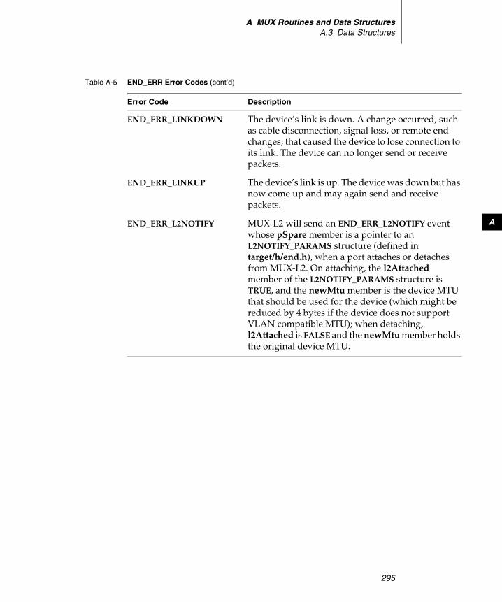
A MUX Routines and Data StructuresA.3 Data Structures
295
A
END_ERR_LINKDOWN The device’s link is down. A change occurred, such as cable disconnection, signal loss, or remote end changes, that caused the device to lose connection to its link. The device can no longer send or receive packets.
END_ERR_LINKUP The device’s link is up. The device was down but has now come up and may again send and receive packets.
END_ERR_L2NOTIFY MUX-L2 will send an END_ERR_L2NOTIFY event whose pSpare member is a pointer to an L2NOTIFY_PARAMS structure (defined in target/h/end.h), when a port attaches or detaches from MUX-L2. On attaching, the l2Attached member of the L2NOTIFY_PARAMS structure is TRUE, and the newMtu member is the device MTU that should be used for the device (which might be reduced by 4 bytes if the device does not support VLAN compatible MTU); when detaching, l2Attached is FALSE and the newMtu member holds the original device MTU.
Table A-5 END_ERR Error Codes (cont’d)
Error Code Description

Wind River Network Stack for VxWorks 6Programmer's Guide, Volume 3: Interfaces and Drivers, 6.6
296
A.3.6 END_MEDIA
This structure is used by the EIOCGIFMEDIA and EIOCSIFMEDIA ioctls.
In the case of the EIOCGIFMEDIA ioctl, the driver sets the endMediaActive member of the specified END_MEDIA structure to indicate the current link mode, according to the conventions defined in target/h/endMedia.h for the if_media options word. The driver also sets the endMediaStatus member to a combination of the bits IFM_AVALID and IFM_ACTIVE; if IFM_AVALID is set, then the IFM_ACTIVE bit indicates whether the interface has a working link connection (bit set, link up) or not (bit not set, link down). If IFM_AVALID is not set, the IFM_ACTIVE bit is meaningless and the driver is indicating that it does not know whether the device has a good connection to the link.
In the case of the EIOCSIFMEDIA ioctl, the driver attempts to set its current link mode to that specified in the endMediaActive member of the provided END_MEDIA structure.
END_ERR_L2PVID_NOTIFY If a port is attached to MUX-L2, MUX-L2 will send END_ERR_L2PVID_NOTIFY to notify the upper layer of the default PVID used for port-based VLAN tagging. Whenever the tagging decision for a VLAN changes, MUX-L2 sends END_ERR_L2PVID_NOTIFY (if the VID is port-based VLAN) to the upper layer.
END_ERR_L2VID_NOTIFY When MUX-L2 joins the attached port to a VLAN, it sends END_ERR_L2VID_NOTIFY to inform the upper layer if a tagged or untagged frame should be sent for the given VLAN. (802.1Q specifies that a port may transmit untagged frames for some VLANs and VLAN-tagged frames for other VLANs for a given port, but cannot transmit using both formats for the same VLAN.) Whenever the tagging decision for a VLAN changes, MUX-L2 sends END_ERR_L2VID_NOTIFY (if the VID is subnet-based VLAN) to the upper layer.
Table A-5 END_ERR Error Codes (cont’d)
Error Code Description

A MUX Routines and Data StructuresA.3 Data Structures
297
A
A.3.7 END_MEDIALIST
This structure is used by the EIOCGMEDIALIST ioctl. It returns the default media setting and a variable list of media types that the driver supports.
The endMediaList member is an array of variable length specified by endMediaListLen. If the endMediaListLen is smaller than the number of media types supported by the device, the driver’s EIOCGMEDIALIST handler writes the number of media types it supports into the endMediaListLen member of the provided END_MEDIALIST, and returns ENOSPC. Otherwise it copies all of the media types it supports into the endMediaList array, and returns OK.
A.3.8 END_OBJ
An END_OBJ describes a network interface driver to the MUX. The driver allocates this structure and initializes some of its elements within its xLoad( ) routine. The structure is defined in target/h/end.h and is diagramed in Figure A-8.
Figure A-6 The END_MEDIA Class
END_MEDIA
endMediaActive : UINT32endMediaStatus : UINT32
Figure A-7 The END_MEDIALIST Class
END_MEDIALIST
endMediaListDefault : UINT32endMediaListLen : UINT32endMediaList : UINT32[1]

Wind River Network Stack for VxWorks 6Programmer's Guide, Volume 3: Interfaces and Drivers, 6.6
298
The MUX manages some of the elements in this structure, but the driver is responsible for setting and managing others:
node The root of the device hierarchy. The MUX sets the value of this field. The driver should not modify the value of this item.
devObject A pointer to the DEV_OBJ structure for this device (see A.3.2 DEV_OBJ, p.289). The driver must set this value when the MUX calls its xLoad( ) routine.
receiveRtn A function pointer that, by default, references the mux[Tk]Receive( ) routine. The MUX supplies this pointer when the driver is loaded. After the device is both loaded and started, the driver can call this receiveRtn( ) to pass data up to the service layer.
pSnarf, pTyped, pPromisc, pStop These fields point to entries in a table of protocols that bound themselves to this network driver. The MUX manages this list.
Figure A-8 The END_OBJ Structure and Related Structures
END_OBJnode : NODE
attached : BOOLtxSem : SEM_IDflags : longmultiList : LISTnMulti : int
receiveRtn( ) : STATUS
outputFilter : protocol_binding
endStyle : int
pNetPool : NET_POOL_ID
pFuncTable
NET_FUNCS
devObject
DEV_OBJ
name : char[ ]unit : intdescription : char[ ]pDevice : void *
proto_entrypSnarf
pTyped
pPromisc
pStop
DRV_CTRL
nProtoSlots : UINT32
END_OBJ
dummyBinding
endObjID : unsigned short

A MUX Routines and Data StructuresA.3 Data Structures
299
A
nProtoSlots The current size of the protocol table for this device, which may be larger than the current number of bound protocols; this member supports increasing the number of bound protocols beyond the current size of the table, by reallocating a larger table when necessary. This is used internally by the implementation.
endStyle Indicates whether this is an END or NPT driver.
attached This member is presently unused, except that it is set to TRUE during the call to endM2Init( ) from the driver’s load routine.
txSem A semaphore that controls access to the device’s transmission facilities. The MUX initializes txSem, but the driver gives and takes the semaphore as needed.
flags A value constructed by ORing combinations of the following flags:
– IFF_ALLMULTI – This device receives all multicast packets.– IFF_BROADCAST – The broadcast address is valid.– IFF_DEBUG – Debugging is on.– IFF_LINK0 – A per link layer defined bit.– IFF_LINK1 – A per link layer defined bit.– IFF_LINK2 – A per link layer defined bit.– IFF_LOOPBACK – This is a loopback net.– IFF_MULTICAST – The device supports multicast.– IFF_NOARP – There is no address resolution protocol.– IFF_NOTRAILERS – The device must avoid using trailers.– IFF_OACTIVE – Transmission in progress.– IFF_POINTOPOINT – The interface is a point-to-point link.– IFF_PROMISC – This device receives all packets.– IFF_RUNNING – The device has successfully allocated needed resources.– IFF_SIMPLEX – The device cannot hear its own transmissions.– IFF_UP – The interface driver is up.
Flags that indicate general capabilities or properties of the device (IFF_SIMPLEX, IFF_MULTICAST, IFF_BROADCAST, and IFF_NOTRAILERS) are set by the endM2Init( ) call made from the driver’s xLoad( ) routine, and do not change thereafter. The driver controls the IFF_UP and IFF_RUNNING flags, setting these flags in its start routine, and clearing them in its stop routine. The IFF_OACTIVE flag is not used in the current stack. Applications or protocols

Wind River Network Stack for VxWorks 6Programmer's Guide, Volume 3: Interfaces and Drivers, 6.6
300
may change only some flags through the muxIoctl( ) command, those specified in the IFF_END_MODIFIABLE mask in target/h/wrn/coreip/net/if.h. The flags most commonly changed in this way are IFF_PROMISC and IFF_ALLMULTI. In particular, the IFF_UP flag is not controlled in this way, but by means of calls to muxDevStart( ) or muxDevStop( ).
pFuncTable A pointer to a NET_FUNCS structure (see A.3.17 NET_FUNCS, p.308). This structure contains pointers to driver routines that handle standard requests to the device. The driver allocates and initializes this structure when the MUX calls its xLoad( ) routine.
multiList A list of multicast addresses for which the device is configured to receive frames. Network services or applications use MUX functions to add addresses to or remove addresses from this list, ultimately relying on the driver’s xMCastAddrAdd( ), xMCastAddrDel( ), and xMCastAddrGet( ) to manage the list.
nMulti The number of addresses on the list referenced by the multiList field described above. This is adjusted by the driver’s xMCastAddrAdd( ) and xMCastAddrDel( ) routines. It records the total number of addresses in the table, not the total references to those addresses, which may be larger.
outputFilter If not NULL, a pointer to the structure representing a binding instance of a single MUX_PROTO_OUTPUT service bound to the network device. The service’s xStackRcvRtn( ) is called for each packet sent to the device.
pNetPool A pointer to a netBufLib-managed memory pool. The driver initializes this pool in the driver’s xLoad( ) routine.
dummyBinding This is used internally by muxTkCookieGet( ) to implement a fake protocol binding cookie for a network device.
endObjId An interface index assigned by muxL2VlanPortAttach( ) and used by the MUX L2 code to identify the network device. This is not used when MUX L2 is not supported.

A MUX Routines and Data StructuresA.3 Data Structures
301
A
A.3.9 END_RCVJOBQ_INFO
This structure, shown in Figure A-9, is used by the EIOCGRCVJOBQ ioctl to retrieve the job queue IDs of the queues that a network device uses to deliver packets to the stack. Currently only a single job queue is allowed per interface, but in a future release there may be more than one, so this mechanism is designed to report multiple queues.
The MUX initializes numRcvJobQs with the number of available slots in the array qIds before the MUX calls the driver’s xIoctl( ) routine. The driver then checks this value:
■ If it is less than the actual number of job queues that the interface uses to deliver received packets to the stack, the driver sets numRcvJobQs to the actual number of queues it uses, does not modify the qIds array, and returns ENOSPC.
■ If it is equal to or greater than the actual number of job queues that the interface uses to deliver received packets to the stack, the driver sets numRcvJobQs to the actual number of queues it uses, writes the job queue IDs of these queues into the qIds array (in any convenient order), and returns OK.
A.3.10 END_QUERY
When the MUX sends an EIOCQUERY command to a driver’s xIoctl( ) routine, it sets the data parameter to an END_QUERY object, as shown in Figure A-10. The MUX sets the query field of this structure to the type of query (for instance, END_BIND_QUERY), and the queryLen field to the size of the queryData buffer. Upon receipt of an EIOCQUERY command, the driver’s xIoctl( ) routine should either copy data into this queryData buffer, or return an error value such as EINVAL.
Figure A-9 The END_RCVJOBQ_INFO Class
END_RCVJOBQ_INFO
numRcvJobQs : UINT32qIds : JOB_QUEUE_ID[]
number of job queues on which the interface delivers packetsarray of job queue IDs

Wind River Network Stack for VxWorks 6Programmer's Guide, Volume 3: Interfaces and Drivers, 6.6
302
A.3.11 LL_HDR_INFO
The MUX uses the LL_HDR_INFO structure to keep track of link-level header information associated with packets that a driver passes to the MUX and the MUX then passes to a network service. An END driver sets the members of an LL_HDR_INFO structure in its xPacketDataGet( ) routine. The LL_HDR_INFO structure is illustrated in Figure A-11.
A.3.12 M_BLK
An M_BLK chains together segments of packets. Use these structures as a vehicle for passing packets between the driver and protocol layers. It keeps track of the size of packets and packet segments and points to other links in the segment chain. It provides the control structure for data in clusters. Figure A-12 shows the M_BLK object.
Figure A-10 The END_QUERY Class
END_QUERYquery : intqueryLen : int
the query varietylength of the expected or actual data
queryData : char[] four-byte minimum, 120-byte maximum
Figure A-11 The LL_HDR_INFO Class
LL_HDR_INFO
destAddrOffset : int
srcAddrOffset : intsrcSize : intctrlAddrOffset : intctrlSize : intpktType : int
destSize : int
dataOffset : int
offset into the packet where the destination address starts
size of the destination address, in bytes
offset into the packet where the source address starts
size of the source address, in bytes
(reserved for future use)
(reserved for future use)
type of packet (see RFC 1700 ETHER TYPES and other sources)
offset into the M_BLK where the network layer header starts;size of the link header
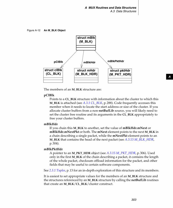
A MUX Routines and Data StructuresA.3 Data Structures
303
A
The members of an M_BLK structure are:
pClBlk Points to a CL_BLK structure with information about the cluster to which this M_BLK is attached (see A.3.1 CL_BLK, p.288). Code frequently accesses this member when it needs to locate the start address or size of the cluster. If you allocate cluster buffers from a non-netBufLib source, you will likely need to set the cluster free routine and its arguments in the CL_BLK appropriately to free your cluster buffers.
mBlkHdr If you chain this M_BLK to another, set the value of mBlkHdr.mNext or mBlkHdr.mNextPkt or both. The mNext element points to the next M_BLK in a chain describing a single packet, while the mNextPkt element points to an M_BLK that contains the head of the next packet (see A.3.13 M_BLK_HDR, p.304).
mBlkPktHdr A pointer to an M_PKT_HDR object (see A.3.15 M_PKT_HDR, p.306). Used only in the first M_BLK of the chain describing a packet, it contains the length of the whole packet, checksum offload information for the packet, and other fields that may be useful to certain software components.
See 2.3.1 Tuples, p.13 for an in-depth exploration of this structure and its members.
It is easiest to set appropriate values for the members of an M_BLK structure and the structures referenced by an M_BLK structure by calling the netBufLib routines that create an M_BLK/CL_BLK/cluster construct.
Figure A-12 An M_BLK Object
struct mBlk(M_BLK)
struct clBlk(CL_BLK)
struct mHdr(M_BLK_HDR)
struct pktHdr(M_PKT_HDR)
pClBlk mBlkPktHdrmBlkHdr
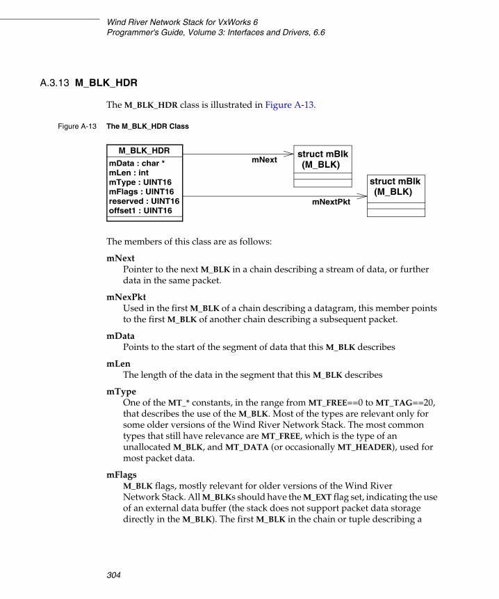
Wind River Network Stack for VxWorks 6Programmer's Guide, Volume 3: Interfaces and Drivers, 6.6
304
A.3.13 M_BLK_HDR
The M_BLK_HDR class is illustrated in Figure A-13.
The members of this class are as follows:
mNext Pointer to the next M_BLK in a chain describing a stream of data, or further data in the same packet.
mNexPkt Used in the first M_BLK of a chain describing a datagram, this member points to the first M_BLK of another chain describing a subsequent packet.
mData Points to the start of the segment of data that this M_BLK describes
mLen The length of the data in the segment that this M_BLK describes
mType One of the MT_* constants, in the range from MT_FREE==0 to MT_TAG==20, that describes the use of the M_BLK. Most of the types are relevant only for some older versions of the Wind River Network Stack. The most common types that still have relevance are MT_FREE, which is the type of an unallocated M_BLK, and MT_DATA (or occasionally MT_HEADER), used for most packet data.
mFlags M_BLK flags, mostly relevant for older versions of the Wind River Network Stack. All M_BLKs should have the M_EXT flag set, indicating the use of an external data buffer (the stack does not support packet data storage directly in the M_BLK). The first M_BLK in the chain or tuple describing a
Figure A-13 The M_BLK_HDR Class
M_BLK_HDR
mData : char *mLen : intmType : UINT16mFlags : UINT16reserved : UINT16
struct mBlk(M_BLK)mNext
offset1 : UINT16
struct mBlk(M_BLK)
mNextPkt

A MUX Routines and Data StructuresA.3 Data Structures
305
A
packet should have the M_PKTHDR flag set, indicating that the mBlkPktHdr member is valid.
reserved1 The stack uses this member in certain instances to record the network service type of a packet; for example, in muxAddressForm( ) and muxLinkHeaderCreate( ), the pDstAddr M_BLK argument has the mBlkHdr.reserved member set to the desired network service type value, in network byte order.
offset1 This value is set in muxTkReceive( ) and muxTkPollReceive( ) to the size of the link layer header, that is: the offset from the start of the link header to the start of the network layer header.
A.3.14 M_LINK
The linkBufPool back end joins the two control objects CL_BLK and M_BLK into a contiguous M_LINK object (see Figure A-14). The linkBufPool back end sets the pClBlk member of the mBlk member of an M_LINK to point at the clBlk member of the same M_LINK, and requires that other software does not change this. Keeping the M_BLK and CL_BLK contiguous in the M_LINK allows some optimization in the linkBufPool allocation and freeing routines.
Figure A-14 An M_LINK Object
struct _M_LINK(M_LINK)
struct clBlk(CL_BLK)
struct mBlk(M_BLK)
clBlk mBlk
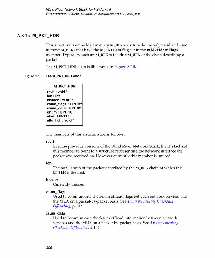
Wind River Network Stack for VxWorks 6Programmer's Guide, Volume 3: Interfaces and Drivers, 6.6
306
A.3.15 M_PKT_HDR
This structure is embedded in every M_BLK structure, but is only valid and used in those M_BLKs that have the M_PKTHDR flag set in the mBlkHdr.mFlags member. Typically, such an M_BLK is the first M_BLK of the chain describing a packet.
The M_PKT_HDR class is illustrated in Figure A-15.
The members of this structure are as follows:
rcvif In some previous versions of the Wind River Network Stack, the IP stack set this member to point to a structure representing the network interface the packet was received on. However currently this member is unused.
len The total length of the packet described by the M_BLK chain of which this M_BLK is the first.
header Currently unused.
csum_flags Used to communicate checksum offload flags between network services and the MUX on a packet-by-packet basis. See 4.6 Implementing Checksum Offloading, p.102.
csum_data Used to communicate checksum offload information between network services and the MUX on a packet-by-packet basis. See 4.6 Implementing Checksum Offloading, p.102.
Figure A-15 The M_PKT_HDR Class
M_PKT_HDR
rcvif : void *len : intheader : VOID *csum_flags : UINT32csum_data : UINT32
struct mBlk(M_BLK)aux
qnum : UINT16vlan : UINT16altq_hdr : void *
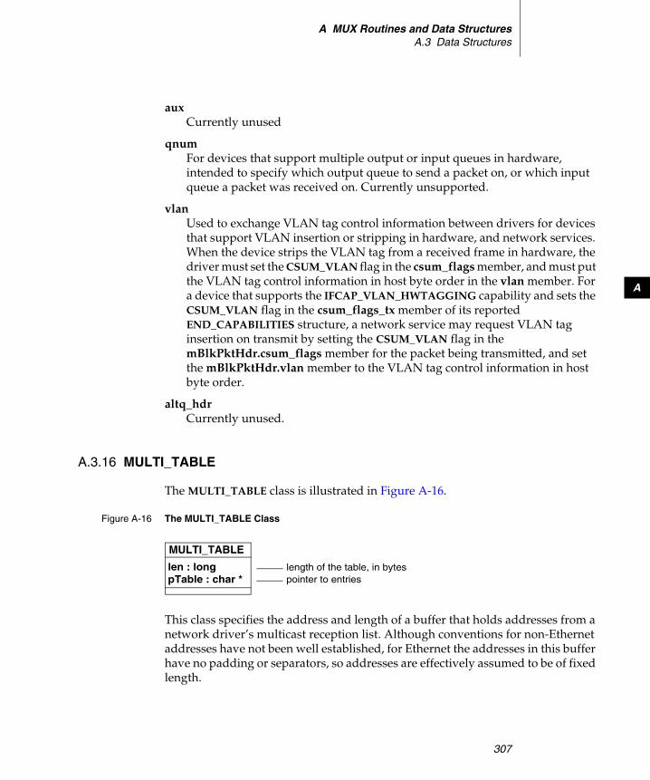
A MUX Routines and Data StructuresA.3 Data Structures
307
A
aux Currently unused
qnum For devices that support multiple output or input queues in hardware, intended to specify which output queue to send a packet on, or which input queue a packet was received on. Currently unsupported.
vlan Used to exchange VLAN tag control information between drivers for devices that support VLAN insertion or stripping in hardware, and network services. When the device strips the VLAN tag from a received frame in hardware, the driver must set the CSUM_VLAN flag in the csum_flags member, and must put the VLAN tag control information in host byte order in the vlan member. For a device that supports the IFCAP_VLAN_HWTAGGING capability and sets the CSUM_VLAN flag in the csum_flags_tx member of its reported END_CAPABILITIES structure, a network service may request VLAN tag insertion on transmit by setting the CSUM_VLAN flag in the mBlkPktHdr.csum_flags member for the packet being transmitted, and set the mBlkPktHdr.vlan member to the VLAN tag control information in host byte order.
altq_hdr Currently unused.
A.3.16 MULTI_TABLE
The MULTI_TABLE class is illustrated in Figure A-16.
This class specifies the address and length of a buffer that holds addresses from a network driver’s multicast reception list. Although conventions for non-Ethernet addresses have not been well established, for Ethernet the addresses in this buffer have no padding or separators, so addresses are effectively assumed to be of fixed length.
Figure A-16 The MULTI_TABLE Class
MULTI_TABLE
len : long length of the table, in bytespTable : char * pointer to entries

Wind River Network Stack for VxWorks 6Programmer's Guide, Volume 3: Interfaces and Drivers, 6.6
308
A.3.17 NET_FUNCS
A driver uses this structure to expose an interface to the MUX. See Figure 4-1 for a schematic of this interface that shows how it differs in ENDs and NPT drivers. The driver routines referred to in this structure are described in greater detail elsewhere (see Driver Implementations of the NET_FUNCS Interface, p.131).
Index
Numerics802.1Q VLAN, see VLAN
AacceptRtn, see xAcceptRtn( )ADDR_RES_FUNC 183, 271address learning (802.1Q) 211addresses
virtual, translating 163addresses, see also Internet addressesaddrGet( ), see xAddrGet( )AF_INET 194AF_INET6 194AF_PACKET 194AF_ROUTE 194altq_hdr 15anchor, shared-memory 66anycast, specifying 36ARP, Auto IP and 50association lists 163attaching a stack to a network interface
overview of 33explicitly, manually started interfaces 32
ATTR_AC_ISR 19ATTR_AC_SH_ISR 19ATTR_AI_ISR 19
ATTR_AI_SH_ISR 19Auto IP 47
configuring 48multiple interfaces and 50using 50
autoIP announce wait time 49autoIP announcements interval 49autoIP defensive interval 50autoIP interface list 47, 48autoIP max conflicts 50autoIP max probe time 49autoIP min probe time 49autoIP number of announcements 49autoIP probe count 49autoIP probe wait time 48autoIP rate limit interval 50aux, M_BLK field 15
Bbackplane processor numbers 64backplane, shared memory 63backplanes
processor numbers 64shared-memory networks, using with 64
bcastFlag 156bindRtn 195boot line parameters
309

Wind River Network Stack for VxWorks 6 Programmer's Guide, 6.6
shared-memory network example 78BOOTP
compare with RARP 51BSD drivers
entry points, implementing 160porting to MUX 159
buffer addresses, translating 163BUS_INT 77_BYTE_ORDER 164
C_CACHE_ALIGN_SIZE 10CACHE_DRV_VIRT_TO_PHYS( ) 164cacheUserFuncs 164cap_available 291
checksum offloading 104VLAN tagging 206
cap_enabled 291checksum offloading 104
.cdf filesadding VxBus network drivers 114network services and 181
checksum offloadingexample code 106, 108implementing 102receiving data 104sending data 106xPollRcv( ) 155
CL_BLK 12, 13, 16, 288CL_BLK_LIST 288CL_DESC 23CL_POOL 23Classifier 224classifier_rule 229, 248clBlk, see CL_BLKclBlkList 288clBlkNum 22clDesc see CL_DESC 23clDescTblNumEnt 19, 23close( )
socket descriptors 193closeRtn 195CLS_RULE_x 229
cluster block, see CL_BLKclusters 12
definition of 12determining address of 13
COMM_END 92command-and-control module (network driver
component) 93configNet.h 89
adding network drivers 115network driverss, adding 115
configure( ) 255connectRtn 195connectWithTimeoutRtn 195container queues 237, 247
filter rule addition 241filter rule deletion 242Hierarchy Token Bucket Container (HTBC)
250multi-band container (MBC) 250
cookie 183count( ) and count_locked( ) 254CSUM flags 291csum_data 103, 105, 306CSUM_DATA_VALID
where set 105csum_flags 103, 105, 107, 306csum_flags_rx 291csum_flags_tx 291CSUM_FRAGMENT 292CSUM_IP 106, 292CSUM_IP_CHECKED 105
where set 105CSUM_IP_FRAGS 292CSUM_IP_HDRLEN( ) 106CSUM_IP_VALID
where set 105CSUM_PSEUDO_HDR
where set 105CSUM_TCP 106, 292CSUM_TCP_SEG 293CSUM_TCPv6 106, 293CSUM_TCPv6_SEG 293CSUM_UDP 106, 292CSUM_UDPv6 106, 293CSUM_VLAN 307
310
Index
Index
CSUM_XPORT_CSUM_OFF( ) 107
Ddefault route, adding to route table 42DEFAULT_CPUS_MAX 78dequeue( ) and dequeue_locked( ) 254destroy( ) 233, 255DEV_OBJ 289device link status 43devInstanceConnect( ) 111, 112, 113devInstanceInit( ) 111, 112devInstanceInit2( ) 111, 113, 132, 133
xLoad( ) and 129devname 33devProbe 112DHCP
auto-configuration 36Differentiated Services (build component) 224differentiated services, see DiffServDiffServ 224
behavior aggregate mode 225configuration components 224configuring 224meter/marker entities 232multi-field mode 225
direct memory access, see DMADMA 165
scatter-gather 96DMA buffers
reclaiming 94DMA descriptors
allocating 163DMA engine 93
checksum offloading 102domainMap 194domainReal 194driver registration files 115drop presence-aware FIFO (DPAF) queues 244DRV_CTRL 290
allocating 162created by xLoad( ) 90releasing 134retrieving for a device 265
drvBusFuncs 110ds class 231, 235, 236DS codepoint 224DS field 224ds_data 231ds_filter 228, 229ds_map 231, 232ds_sm 231, 235ds_srtcm 231, 236dscpQosHook( ) 262dump( ) 254
EEAGAIN 280EALREADY
xUnload( ) 135EIOCGADDR 137, 138, 142EIOCGFLAGS 138, 142EIOCGHDRLEN 143EIOCGIFCAP 140, 142, 293
checksum offloading 103handling 103VLAN tagging 206
EIOCGIFMEDIA 140, 142, 296EIOCGIFMTU 141EIOCGMEDIALIST 139, 142, 297EIOCGMIB2 139, 143, 177EIOCGMIB2233 139, 143, 177EIOCGMTU 143EIOCGNPT 136, 137, 142EIOCGPOLLCONF 139, 143, 177EIOCGPOLLSTATS 139, 143, 177EIOCGRCVJOBQ 141, 143, 301EIOCMULTIADD 137, 138, 142EIOCMULTIDEL 137, 138, 143EIOCMULTIGET 138, 143EIOCPOLLSTART 139, 143, 151EIOCPOLLSTOP 139, 143EIOCQUERY 88, 143, 144, 158, 301
xEndBind( ) and 117EIOCSADDR 137, 138, 142EIOCSFLAGS 138, 142, 144EIOCSIFCAP 141, 142, 293
311
Wind River Network Stack for VxWorks 6 Programmer's Guide, 6.6
checksum offloading 103handling 104
EIOCSIFMEDIA 140, 296EIOCSIFMTU 141, 143END (Enhanced Network Driver)
see also network driversadding to an image 109compared to NPT drivers 82entry points
compared with NPT driver 82list exported to MUX 131
generic VxBus driver template 108implementing 108ioctl support 136receiving frames 118service bind event, response to 117template for 82
END interface support 86, 202END_BIND_QUERY 117, 144, 158END_CAPABILITIES 142, 290, 307
checksum offloading 103VLAN tagging 206
END_ERR 189, 270, 293END_ERR_BLOCK 97, 145, 146, 184, 190, 283, 284,
285END_ERR_DOWN 294END_ERR_FLAGS 294END_ERR_INFO 294END_ERR_L2NOTIFY 295END_ERR_L2PVID_NOTIFY 296END_ERR_L2VID_NOTIFY 296END_ERR_LINKDOWN 295END_ERR_LINKUP 295END_ERR_NO_BUF 294END_ERR_RESET 294END_ERR_UP 294END_ERR_WARN 294END_IFCOUNTERS 143, 176END_IFDRVCONF 143, 176END_MACROS 126END_MEDIA 142, 296END_MEDIALIST 142, 297END_OBJ 128, 297
ENDs, and 126establishing 129
populated how 128releasing 134retrieving for a device 265
END_OBJ_INIT( ) 129, 290END_QUERY 88, 143, 301END_QUERY structure
bind calls, responding to 117xIoctl( ) and 144
END_RCV_RTN_CALL( ) 85, 126, 175END_RCVJOBQ_INFO 143, 301END_TX_SEM_GIVE( ) 95, 133END_TX_SEM_TAKE( ) 95, 132end8023AddressForm( ) 84, 156endBind (NET_FUNCS member) 158endDevTbl[ ] 89, 268
dynamic changes to 116editing 116ENDs and NPT drivers mixed 117network drivers, and 115
endEtherAddressForm( ) 84, 156endEtherPacketAddrGet( ) 84, 157endEtherPacketDataGet( ) 84, 157endFindByName( ) 265endLib 84, 86, 130, 165endLib.h 126endM2Free( ) 176endM2Init( ) 130
example 176endM2Packet( ) 175
examples 178endMediaList 297endMediaListLen 297endMediaStatus 296endObjInit( ) 290endPollStatsInit( ) 177endPool 165endPoolCreate( ) 130endPoolDestroy( ) 135endPoolJumboCreate( ) 130enqueue( ) and enqueue_locked( ) 254esm (boot device) 66etherhooks 161etherInputHook( ) 160, 161etherMultiAdd( ) 148etherMultiDel( ) 149
312

Index
Index
etherMultiGet( ) 151Ethernet multicast library support 202etherOutputHook( ) 160, 161etherQosHook( ) 262etsecRegister( ) 109
Ff_insert( ) 254f_remove( ) 254FIFO queues 243filter rules 247FIONBIO 200FIONREAD 200FIOSELECT 200FIOUNSELECT 200flow control 146FOLDER_AUTOIP 47formAddress( ), see xFormAddress( )forward declaration files 115free queue 100
GGARP VLAN Registration Protocol 211gateway 34gateway inet boot parameter 78gateway6 34gateways
example 75GEI_INT_PENDING 120gei825xxVxbEnd.c 109, 111, 118geiDevPciRegistration 111geiIntStatus 120geiRegister( ) 110General Purpose Platform
QoS and 257getpeernameRtn 195getsocknameRtn 195getsockopt( ) 216getsockoptRtn 195gif devices 51
GRE tunnels 37GVRP 211
HhcfDeviceList[ ] 115header (M_PKT_HDR field) 15heartbeat, shared-memory 67host name
adding to host table 32assigning to an address 43
host route, adding to route table 41host table, viewing 33hostAdd( ) 32
assigning a host name to an address 43hosts 73
example 75hosts.equiv 73
example 75hostShow( ) 33htole16( ) 164htole32( ) 164hwconf.c 89
configuring PLB bus drivers 115device configuration 111PLB device configuration 112
Iif_media 296IF_OUTPUT_FUNC 183, 271IFCAP_CAP0, IFCAP_CAP1, IFCAP_CAP2 292IFCAP_IPCOMP 292IFCAP_IPSEC 292IFCAP_JUMBO_MTU 292IFCAP_RXCSUM 104, 292IFCAP_TCPSEG 292IFCAP_TXCSUM 292IFCAP_VLAN_HWTAGGING 292, 307IFCAP_VLAN_MTU 292ifconfig( ) 32, 33
accessing with ipnet_cmd_ifconfig( ) 89
313

Wind River Network Stack for VxWorks 6 Programmer's Guide, 6.6
commands 36configuring a network interface with 38network interface starting and enabling 43reconfiguring a network interface 42retrieving interface information with 38using 35VLAN 213
examples 215IFCONFIG_n 33, 51ifEndObj 177IFF_ALLMULTI 149, 299IFF_BROADCAST 144, 299IFF_DEBUG 299IFF_END_MODIFIABLE 300IFF_LINK0, IFF_LINK1, IFF_LINK2 299IFF_LOOPBACK 299IFF_MULTICAST 144, 149, 299IFF_NOARP 299IFF_NOTRAILERS 299IFF_OACTIVE 299IFF_POINTOPOINT 299IFF_PROMISC 299IFF_RUNNING 43, 299IFF_SIMPLEX 144, 299IFF_UP 43, 144, 299IFM_ACTIVE 296IFM_AVALID 296ifname 33ifPollInterval 176IFQ_ID_NONE 239ifq_type 238ifqueue_container 247, 250, 251ifqueue_dpaf 238ifqueue_fifo 238, 243ifqueue_filter 241, 247, 248ifqueue_htbc 238, 251ifqueue_mbc 238, 250ifqueue_netemu 238, 245ifqueue_qos 237, 238, 240, 241, 243, 245, 250, 251ifquque_data 238ifValidCounters 176in_addr_union 229, 248INCLDUE_SM_COMMON 67INCLUDE_END 86, 202INCLUDE_ETHERNET 202
INCLUDE_IFCONFIG 35INCLUDE_IPAIP 47, 48INCLUDE_IPATTACH 34INCLUDE_IPCOM_SYSVAR_CMD 44, 48INCLUDE_IPIFCONFIG_CMD 47INCLUDE_IPNET 10INCLUDE_IPNET_CLASSIFIER 224INCLUDE_IPNET_DIFFSERV 224INCLUDE_IPNET_DS_SM 225INCLUDE_IPNET_DS_SRTCM 225INCLUDE_IPNET_IFCONFIG_n 33, 89INCLUDE_IPNET_PACKET_POOL_n 8INCLUDE_IPNET_USE_PACKET_POOL 8INCLUDE_IPNET_USE_TUNNEL 52INCLUDE_IPNET_USE_VLAN 202INCLUDE_IPQOS_CMD 225INCLUDE_IPQUEUE_CONFIG_CMD 225INCLUDE_IPRADVD 44INCLUDE_L2CONFIG 203INCLUDE_LINKBUFPOOL 12INCLUDE_MUX 86, 87INCLUDE_MUX_L2 202INCLUDE_NET_DAEMON 125INCLUDE_NET_POOL 25, 26, 147, 266INCLUDE_NETBUFADVLIB 13, 17INCLUDE_NETBUFLIB 13, 21INCLUDE_NETBUFPOOL 12INCLUDE_NETPOOLSHOW 13INCLUDE_QOS_INGRESS 260INCLUDE_ROUTECMD 41INCLUDE_SM_COMMON 75INCLUDE_SM_NET 75INCLUDE_SM_NET_SHOW 75INCLUDE_SM_SEQ_ADDR 73inet 33inet on backplane boot parameter 71, 78INET_IPAIP_ANNOUNCE_INTERVAL 49INET_IPAIP_ANNOUNCE_NUM 49INET_IPAIP_ANNOUNCE_WAIT 49INET_IPAIP_DEFEND_INTERVAL 50INET_IPAIP_IFNAME_LIST 47, 48INET_IPAIP_MAX_CONFLICTS 50INET_IPAIP_PROBE_MAX 49INET_IPAIP_PROBE_MIN 49INET_IPAIP_PROBE_NUM 49
314
Index
Index
INET_IPAIP_PROBE_WAIT 48INET_IPAIP_RATE_LIMIT_INTERVAL 50inet6 34Ingress default deferred Job Queue Priority 260ingress filter routine 261ingress filtering 257
configuration components 260jobQueueLib 258multiple interfaces 259
Ingress QoS Job Queue 258, 260Ingress Traffic Prioritization 260Ingress Traffic Prioritization Job Queue Priority
260init( ) 255INIT_RTN
VxBus network drivers 114input queue
processors, shared memory 69interface output queues 237
adding 240retrieving 241
interfaces, see network interfacesInternet addresses
adding to the route table 40assigning to an interface 32correcting interface assignment errors 42
interrupt cause register 119interrupt handlers
receiving frames 121interrupt service routines
driverregistering 118
registering 132interrupts
driver handler 118receive see receive interruptstransmit-complete see transmit-complete
interruptsintrCtlrCpu 125ioctl commands 272ioctl( )
see also xIoctl( )socket descriptors 193
ioctlRtn see xIoctlRtn( )ioctls
socketmemory validation 199
IP addresses, example 4IP_MAX_UNITS 32IP_SO_X_PKT_MPRIO 10IP_SOL_SOCKET 10ipAttach( ) 32, 34, 89, 180
example 181IPCOM 10IPCOM ifconfig commands 47IPCOM output queue commands 225IPCOM QoS commands 225ipcom_drv_eth_init( ) 89, 180
example 180IPCOM_IF_DRV_CAP_VLAN_HWTAGGING_
RX 206IPCOM_IF_DRV_CAP_VLAN_HWTAGGING_
TX 206IPCOM_IF_DRV_CAP_VLAN_MTU 206ipcom_pkt.h 9ipcom_pkt_malloc( ) 11IPCOM_PKT_MPRIO_* 9IPCOM_PKT_MPRIO_DEFAULT 8, 10IPCOM_PKT_MPRIO_DRV 10IPCOM_PKT_MPRIO_MAX 8, 9, 10IPCOM_PKT_MPRIO_MIN 8, 10IPCOM_PKT_MPRIO_STACK 8, 10IPCOM_PKT_PRIO_STACK 9IPCOM_VXWORKS_USE_MUX_L2 202ipDetach( ) 34IPNet packet pool configurations 8IPNet packet pool support 8ipnet.inet.linklocal.ANNOUNCE_INTERVAL 49ipnet.inet.linklocal.ANNOUNCE_NUM 49ipnet.inet.linklocal.ANNOUNCE_WAIT 49ipnet.inet.linklocal.DEFEND_INTERVAL 50ipnet.inet.linklocal.interfaces 48ipnet.inet.linklocal.MAX_CONFLICTS 50ipnet.inet.linklocal.PROBE_MAX 49ipnet.inet.linklocal.PROBE_MIN 49ipnet.inet.linklocal.PROBE_NUM 49ipnet.inet.linklocal.PROBE_WAIT 48ipnet.inet.linklocal.RATE_LIMIT_INTERVAL 50ipnet.inet.rtdisc.PerformRouterDiscovery 46ipnet.inet6.AcceptRtAdv 44
315
Wind River Network Stack for VxWorks 6 Programmer's Guide, 6.6
ipnet.inet6.radvd sysvarsAdvAutonomousFlag 46AdvHomeAgentFlag 45AdvHomeAgentOpt 45AdvHomeAgentOptLifetime 45AdvHomeAgentOptPreference 45AdvIntervalOpt 45AdvManagedFlag 45AdvOnLinkFlag 46AdvOtherConfigFlag 45AdvPreferredLifetime 46AdvPrefixList 46AdvRouterAddressFlag 46AdvValidLifetime 46MaxRtrAdvInterval 45MinDelayBetweenRAs 46MinRtrAdvInterval 45prefix 46
IPNET_CACHE_BUFSIZE 10ipnet_cmd_ifconfig( ) 89ipnet_conf_pkt_pool[ ] 11ipnet_config.c 11IPNET_DIFFSERV_CLASSIFIER_MODE_BA 225Ipnet_diffserv_handlers 232, 235, 236Ipnet_diffserv_handlers_template 233ipnet_diffserv_init( ) 234ipnet_diffserv_register_ctor( ) 234ipnet_diffserv_srtcm_template( ) 234Ipnet_ifqueue structure 237Ipnet_ifqueue_container structure 247Ipnet_netif_struct 253Ipnet_pkt_queue 252, 253
defined 252Ipnet_pkt_queue_container 253ipnet_pkt_queue_init( ) 252ipnet_pkt_queue_register( ) 252ipnet_radvd daemon 44Ipnet_simple_marker 235Ipnet_srtcm 236IPNET_USE_RFC1256 44ipProtoQosHook( ) 262IPv4 auto-configuration, see Auto IPIPv4 AutoIP Components 47IPv6
hostname, assigning an address to 43
Jjob queues, network 121
multiple 125JOB_QUEUE_ID 121jobQLib 260jobQueueLib 122, 258
transmit-complete interrupt handler 100jobQueueLib.h 122jobQueuePost( )
network job queues 121
Ll2Attached 295l2config 203, 212
examples 212L2NOTIFY_PARAMS 295leaf queues 237, 242
drop presence-aware FIFO (DPAF) 244FIFO 243Ipnet_pkt_queue 252network emulator (netemu) 245
Learning BridgeMUX-L2 and 211
libInitRtn see xSockLibInit( )link status 43link_cookie 206linkBufPool 12, 18, 130, 165
alignment requirements of 22cluster size limitations 19cluster size restrictions of 23M_LINK 305netPoolInit( ) and 22
link-level headeradding to a packet 266, 267muxTkReceive( ), and 282xSend( ) and 146
listenRtn 195LL_HDR_INFO 157, 189, 275, 302LOAD_FUNC
network drivers, adding 115LOAD_STRING
network drivers, adding 115
316
Index
Index
location monitors 69LONGSWAP( ) 164
MM_BLK 12, 13, 302
hidden NET_POOL pointer in 22members of 15
M_BLK_HDR 304M_BLK_ID
arrays of, allocating 163M_CL_CONFIG 22m_freem( ) 261M_HEADER 147M_LINK 12, 19, 21, 305M_PKT_HDR 15, 306M_PKTHDR 155, 305, 306M_PREPEND( ) 26, 147m_prepend( ) 26M_PROMISC 147M2_ID 143M2_INTERFACETBL 143mailbox interrupts 69marker_input( ) 233max # of cpus for shared network 65Maximum number of 802.1Q VLANs supports 202maximum transmission unit, see MTUmBlk, see M_BLKmBlkHdr.mData 266mBlkHdr.reserved 266mbuf 13mbuf.h 26, 147mCastAddrAdd( ), see xMCastAddrAdd( )mCastAddrDel( ), see xMCastAddrDel( )mCastAddrGet( ), see xMCastAddrGet( )memArea 22, 23member_to_object( ) 123memory pools 7
buffers 7configuring packet buffer pools 8control structures 7netBufLib 7packet buffers, number of 9packet buffers, size of 9
memory requirements routines 24netBufLib 24
memSize 22, 23meter/marker entities
creating 227, 232deleting 227filter mapping 227filter rule addition 225filter rule deletion 226using 234
meter_input( ) 233miiBus
destroying 114miiMediaUpdate( ) 112miiRead( ) 112miiWrite( ) 112MIN_PRIO_POOL_n 8minimal encapsulation 37Minimum priority level for SIZE_POOL_n packet
pool 8MT_DATA 304MT_FREE 304MT_HEADER 304MT_TAG 304MTU 9, 11, 252MULTI_ADDR_RES_FUNC 183, 271MULTI_TABLE 150, 307multi-band container (MBC) 250multiList 149multiple network drivers
IP_MAX_UNITS 32MUX
API 263driver interface 128OSI model, and 30overview 30service/MUX interface 87
MUX Layer 2 support 202MUX support 86MUX_L2_MAX_VLANS_CFG 202MUX_L2_NUM_PORTS_CFG 202MUX_L2_VLAN_STATS 221MUX_MAX_IFTYPE 270MUX_PROTO_OUTPUT 182, 188MUX_PROTO_PROMISC 182, 188
317
Wind River Network Stack for VxWorks 6 Programmer's Guide, 6.6
in muxTkReceive( ) discussion 282MUX_PROTO_SNARF 182, 188
in muxTkReceive( ) discussion 282muxAddressForm( ) 26, 185, 266, 305muxAddrResFuncAdd( ) 286muxAddrResFuncDel( ) 286muxAddrResFuncGet( ) 287muxBind( ) 88, 181
service functions of 186muxBufInit( ) 161muxDevConnect( ) 89, 90, 112, 114, 132
when called 128muxDevExists( ) 267muxDevLoad( ) 32, 90, 132, 268
called by muxDevConnect( ) 114called by tUsrRoot 87pInitString 115when called 128
muxDevStart( ) 32, 90, 132, 268called by muxDevConnect( ) 114
muxDevStop( ) 92, 269muxDevUnload( ) 92, 134, 185, 269, 290
mutex semaphor 186VLAN 207
muxError( ) 167, 189, 270muxFormAddress( ) 156muxIfFuncAdd( ) 32, 183, 270muxIfFuncDel( ) 183, 271muxIfFuncGet( ) 183, 271muxIfTypeGet( ) 183muxIoctl( ) 272, 300
network services and 185MUX-L2
egress rules 209ingress rules 208
muxL2EgressClassify( ) 206, 209muxL2IngressClassify( ) 206, 207MUXL2IOCSPORTATTACH 206MUXL2IOCSPORTDETACH 207MUXL2IOCSPORTVLAN 205muxL2Ioctl( ) 205, 206, 207, 210
get functionality 212muxL2PortAttach( ) 205
alternative to 206muxL2PortDetach( ) 206, 207
alternative to 207muxL2Show( ) 212, 219
example 219muxL2StatShow( ) 219
example 221muxL2VlanPortAttach( ) 300muxL2VlanShow( ) 212, 219
example 220muxL2VlanStatShow( ) 219
example 221muxLib 87muxLinkHeaderCreate( ) 156, 185, 267, 305muxMCastAddrAdd( ) 148, 272muxMCastAddrDel( ) 273muxMCastAddrGet( ) 273muxPacketAddrGet( ) 157muxPollSend( )
when called 92muxReceive( ) 281muxSend( ) 26, 94, 146, 184, 283muxShow( ) 275, 290muxTkBind( ) 88, 181, 275
service functions of 186muxTkCookieGet( ) 89, 279, 300muxTkDrvCheck( ) 181, 279muxTkLib 87muxTkPollReceive( ) 153, 280muxTkPollSend( ) 151, 281muxTkReceive( ) 282muxTkSend( ) 26, 94, 146, 184, 284muxTxRestart( ) 97, 145, 146, 285
transmit mutex and 127muxUnbind( ) 92, 185, 186, 285
NNB_BUFTYPE_CL_BLK 24NB_BUFTYPE_CLUSTER 24NB_BUFTYPE_M_BLK 24neighbor discovery 52NET_DAEMONS_CPU_AFFINITY 125NET_FUNCS 83, 131, 300NET_POOL 18, 22
hidden pointer in M_BLK 22
318

Index
Index
NET_POOL_NAME_SZ 18NET_TASK_QJOB_PRI 122, 260NETBUF_ALIGN 21, 22, 23NETBUF_ALIGNED 21NETBUF_CFG 18
attributes 19bMemExtraSize 18bMemPartId 19clDescTblNumEnt 20ctrlNumber 19ctrlPartId 19pClDescTbl 19pDomain 18pName 18
NETBUF_CL_DESC 18, 19, 20NETBUF_LEADING_CLSPACE_DRV 21netBufAdvLib 13netBufCfg see NETBUF_CFGnetBufClDesc see NETBUF_CL_DESCnetBufLib 7, 8, 16, 21, 165
back ends 12linkBufPool 12netBufPool 12nullBufPool 12
buffer pool 12display routines 13
netBufLib poolsattributes of 16creating 16finding 16freeing 16parents and children 16
netBufLib.h 13netBufPool 12, 17
alignment requirements of 22cluster size limitations 19cluster size restrictions of 23netPoolInit( ) and 22
netClBlkGet( ) 15netClBlkJoin( ) 15netClusterGet( ) 15netLib.h 122netmask
assigning to an interface 32setting 37
netMblkChainDup( ) 15netMblkClChainFree( ) 15, 102, 147, 288netMblkClFree( ) 15, 288netMblkClJoin( ) 15netMblkDup( ) 158netMblkGet( ) 15netMblkToBufCopy( ) 15, 152_netMemReqDefault( ) 24netPoolAttach( ) 16netPoolBind( ) 16netPoolCreate( ) 16, 17, 130
example 20netPoolDetach( ) 16netPoolIdGet( ) 16netPoolInit( ) 16, 21
clDescTblNumEnt 23limitations of 17pClDescTbl 23pFuncTbl 24pMclBlkConfig 22pNetPool 22releasing pools created with 135
netPoolNameGet( ) 16netPoolRelease( ) 16, 17, 135netPoolUnbind( ) 17netstat( ) 33, 41netTupleGet( ) 15network buffer pools 165
freeing 135network daemons 124network devices
flags 144loading and starting 90receive handler
example 166, 171stopping and unloading 92
network driversdata structures shared with MUX 128delay mechanisms in 124globally visible routines of 128implementing 108interrupt handlers
example 118, 120launching 117memory, managing 165
319

Wind River Network Stack for VxWorks 6 Programmer's Guide, 6.6
polled mode 92resource requirements 94VxBus
adding to a .cdf file 114methods 114registration routines 109
network emulator (netEmu) queues 245network heartbeat 67network interface drivers
see network driversnetwork interfaces
adding an address to 36assigning an address, netmask, or prefix 35attaching to stack 33bringing up 38configuration
ifconfig( ) 35configuring 38deleting an address from 36detaching and destroying 36displaying information about 32fixing IP address assignment errors 42link address, setting 37MTU, setting 37multiple, optimizing in SMP 124pausing 43reconfiguring 42registering 36retrieving configuration information 35retrieving information about 38starting and enabling 43starting at run time 32
Network Protocol Toolkit drivers, see NPT driversnetwork route, adding to route table 41network services
binding 181binding to an interface 88device control 185ioctl commands for, defining 272issuing driver ioctls 185sending packets 184socket interface, adding a 191subroutines for 186unbinding from an interface 88writing a sublayer 180
NPT driversBSD drivers to, porting 159compared to END drivers 82entry points 82implementing 108ingress filtering and 259ioctl support 136launching 117VLAN 211
nullBufPool 12NUM_DAT_128 266NUM_DAT_CLBLKS 27NUM_DAT_MBLKS 27NUM_DAT_n 27NUM_NET_DAEMONS 125NUM_POOL_n 9, 10NUM_SYS_CLBLKS 26NUM_SYS_MBLKS 26NUM_SYS_n 27, 27Number of ports that the device has 202numRcvJobQs 301
Ooutput services 182
Ppacket buffer pools
configuring 8packet buffers
number of 9size of 9
packet statistics 175packetDataGet( ), see xPacketDataGet( )packets
consuming 183pausing, network interfaces 43pClDescTbl 20pClFreeRtn 289pDrvBusFuncs 112pDst.mBlkHdr.reserved field 156
320
Index
Index
pFuncTablemuxL2PortAttach( ) and 206
pFuncTbl 17PHY
destroying 114_pLinkPoolFuncTbl 18, 24PMA_DAT_n 27PMA_DATPOOL 27PMA_SYS_n 27PMA_SYSPOOL 26pMemReq 24pMemReqRtn 22PMS_DAT_n 27PMS_DATPOOL 27PMS_SYS_n 27PMS_SYSPOOL 26pNetBufCfg 18_pNetPoolFuncTbl 17, 24polled mode 92pollRcv( ), see xPollRcv( )pollSend( ), see xPollSend( )pool, see memory poolsPOOL_FUNC 24, 25pools
attributes of (netBufLib) 16creating (netBufLib) 16finding (netBufLib) 16freeing (netBufLib) 16parent and child (netBufLib) 16
port numberswell-known 180
prefix, assigning to an interface 32Processor Local Bus device drivers 110programmed I/O 93promiscuous mode
enabling and disabling 37promiscuous services 182protocol state functionality, enabling for an
interface 43pseudo-device
creating 36pSockFuncTbl 197pSockIoctlMemVal 199pSockIoctlMemVal( ) 200pUnixIoctlMemVal 199
pUnixIoctlMemVal( ) 200
Qq_get( ) 253q_insert( ) 253q_remove( ) 254QJOB 122
allocation 122example 123reposting 124
QoS 223availibility in Wind River Platforms 3General Purpose Platform and 223ingress filtering 257ingress traffic prioritization 257
QOS_DEFAULT_PRI 260QOS_DEFER_PKT 258, 260, 261QOS_DELIVER_PKT 258, 261QOS_IGNORE_PKT 258, 261QOS_JOBQ 260QOS_JOBQ_PRI 260qosIngressHookSet( ) 262Quality of Service, see QoSqueues
container queues 237, 247Drop Precedence-Aware FIFO (dpaf) queues
244fifo queues 243Hierarchy Token Bucket Container (HTBC)
queues 250interface output queues 237, 240leaf queues 237, 242Multi-Band Container (MBC) queues 249network emulator (netemu) queues 245registering 252
RRARP 34
configuring and using 51server 34
321

Wind River Network Stack for VxWorks 6 Programmer's Guide, 6.6
rcvif 15read( )
socket descriptors 193read-modify-write cycle
shared memory and 68readRtn 195receive descriptors 165
allocating 129, 163receive handler
example 166, 171receive interrupts 121receiver (network driver component) 93receiveRtn 126, 281, 282, 298
END and NPT driver differences 85when it is valid 90
recvfromRtn 195recvmsgRtn 195recvRtn 195requeue( ) and requeue_locked( ) 254reset( ) 254restarting, network interfaces 43RFCs
RFC 1213MIB structure, getting for network driver
143packet statistics 176
RFC 1256router solicitation 46
RFC 1700ETHER TYPES 270
RFC 1853GIF tunnels 52
RFC 2002GRE tunnels 37, 52minimal encapsulation 53
RFC 2233MIB structure, getting for network driver
143packet statistics 176
RFC 2473GIF tunnels 52
RFC 25296over4 tunnels 52
RFC 2674VLAN, static objects 211
RFC 2697single-rate, three-color marker 236
RFC 2784GRE tunnels 52
RFC 2849test and documentation addresses 4
RFC 2893gif devices, style of configured tunnels 56
RFC 30566to4 tunnels 52
RFC 3775router as home agent 45
.rhosts 73example 75
ring, or circular arraytransmit descriptors 100
route tableediting, using routec( ) 40
route table, viewing 33route( ) 40routec( ) 40
usage examples 41routed 75router
advertisement 44solicitation 44
router advertisement 44
Sscatter-gather transmission
supporting 96scMemValidate( ) 199SELECT_IPNET_PACKET_POOL 8send( ), see xSend( )sendmsgRtn 195sendRtn 195sendtoRtn 195setsockopt( ) 216
VLAN examples 217setsockoptRtn 195shared memory
location of 67size of 68
322

Index
Index
shared memory master CPU number 65shared-memory anchor 66
initializing 65shared-memory heartbeat 67
maintaining 65shared-memory network 63
anchor 66specifying in the boot line 66
configuring 73, 75example configuration 73heartbeat 67interrupts, interprocessor 69
types 70multiple on one backplane 65object area 68sequential addressing 71size 68TAS operation size 68test-and-set instruction 68test-and-set type 69troubleshooting 79VxMP and 65
shared-memory network master 65shutdownRtn 195Simple Marker 225simple marker 234SimpleMarker 231, 234Single Rate Three Color Marker 225single-rate, three-color marker 235SIOCGIFFLAGS
example 43SIOCGIFQUEUE 241SIOCMUXL2PASSTHRU 200SIOCMUXPASSTHRU 200SIOCSIFQUEUE 240, 249SIOCXADSFILTER 225SIOCXADSMAP 228SIOCXAIFQFILTER 241SIOCXDDSFILTER 227SIOCXDSCREATE 227SIOCXDSDESTROY 227SIOXDDSMAP 228SIZ_SYS_n 27SIZE_POOL_n 9, 10SM 67
SM_ANCHOR_ADRS 76SM_ANCHOR_OFFSET 76SM_ANCHORS_ADRS 66SM_CPUS_MAX 65, 78SM_INT_* interrupt types 70SM_INT_ARGn 70, 77SM_INT_BUS 76SM_INT_TYPE 70, 76SM_MASTER 65, 77SM_MAX_WAIT 77SM_MEM_ADRS 67, 76SM_MEM_SIZE 68, 76SM_OBJ_MEM_SIZE 68, 76SM_OFF_BOARD 76SM_PKTS_SIZE 77SM_TAS_HARD 69, 78SM_TAS_SOFT 69, 78SM_TAS_TYPE 69, 78smEnd 63smNetShow( ) 79
example 71sample output 72shared-memory network starting addresses,
finding 71SMP
ingress filtering and 257optimizing multiple interfaces 124
snarf services 182, 183so_bkendaux 196, 197SO_VLAN 216SOCK_FUNC 195, 197socket ioctls
memory validation 199socket priority 10
IP_SOL_SOCKET 10socket structure 193socket( ) 192socketRtn, see xSocketRtn( )sockets interface for a new network service
adding 191functions 195
sockLib 191sockLibAdd( ) 193sockLibInit( ) 193sockLibInitRtn 194
323
Wind River Network Stack for VxWorks 6 Programmer's Guide, 6.6
sovlan structure 216srTCM 231, 235srTCM (single-rate, three-color marker) 235stackErrorRtn( ) 276stackRcvRtn( ) 276stackRestartRtn( ) 276, 283stackShutdownRtn( ) 269, 276stall conditions 94start( ), see xStart( )statistics, packet 175stop( ), see xStop( )subnet prefix
setting 37sysBusTas( ) 69sysHwInit( ) 112
VxBus driver initialization 111sysHwInit2( ) 112
VxBus driver initialization 111sysIntConnect( ) 132sysLib 69sysLocalToBusAdrs( ) 164sysSmAnchorAdrs 76sysSmLevel 77sysvar 44
Auto IP configuration, parameters for 48router advertisement, parameters for 45router solicitation, parameters for 46
TTAS operation size 68templateEnd.c 109templateEnd.c (END drivers) 108templateVxbEnd.c 82, 108tentative 34tentative bit
setting and clearing 37test-and-set
shared memory use 68test-and-set type 69TK_RCV_RTN_CALL( ) 86, 126, 175tNet0 124tNet1 125transmit 163
transmit descriptorsallocating 129, 163clean-up 98, 102
SMP issues 100indexing 100queues of free and used 100
transmit-complete interruptsabsent 94excessive 94freeing resources 126frequency control 99handler interlocking flag 95network job pool exhaustion 95resource reclamation 94transmit descriptor clean-up 98
transmitter (network driver component) 93troubleshooting
shared-memory networks 79tunnel endpoint
setting 37tunneling 51
availablity in Wind River Platforms 2configured 52IPv6 packets using a gif 56IPv6 packets using an stf 55multicast 52setting endpoints 52, 53
tunnelsautomatic 52configured 52creating 51gif
example 57, 58varieties of 52
tuple poolsallocating 163
tuples 13chained 15copying chains 15creating manually 15diagram of 14freeing chains 15required by the stack 91
tUsrRootrole in network stack initialization 87
324
Index
Index
txSemxSend( ) takes 95
Uunload( ), see xUnload( )used queue 100user priority (802.1P) 211usrAppInit( ) 125
VVID
changing 214virtual addresses, translating 163virtual router
setting 38VLAN 201
adding support for 202disabling support for 207interface name, setting 38management of 211MUX-L2 extensions for 204pseudo-interfaces, creating 214setsockopt( ) examples 217show routines for 219subnet-based 213tag header 203tagging, availablity in Wind River Platforms 3VID, changing 214
VLAN framespriority-tagged 203untagged 203VLAN-tagged 203
VLAN Pseudo Interface support 202VLAN tag
setting 38VLAN tag header 203vlanQosHook( ) 262VXB_BUS_PLB 111VXB_DEVICE_ID 112, 129, 268VXB_DEVID_DEVICE 111
VXB_PARAMETERS 112vxbDev 112vxbDeviceAnnounce( ) 112vxbDeviceMethod 110vxbDevRegInfo 110vxbDevRegister( ) 110vxbDma memory
releasing 114vxbDmaBufLib 113, 130, 171vxbDrvUnlink( ) 112, 114, 134vxbEndQnumSet( ) 125vxbEtsecEnd.c 109, 110, 120vxbInstUnitSet( ) 113vxbNewDriver( ) 112vxbNextUnitGet( ) 113vxbParams 110vxbPciRegister 110vxbPlbRegister 110vxbRead32( ) 171vxbRegMap( ) 171VXBUS_VERSION_3 111vxbUsrCmdLine.c
generation 115vxbWrite32( ) 171
WWDB agent 92
snarf service 183WDB_COMM_END
snarf service 183xPollRcv( ) 153xPollSend( ) 151
Wind River documentation 4Wind River Platforms, features unique to
802.1Q VLAN tagging 3, 201QoS 3, 223, 257tunneling 2, 30
WORDSWAP( ) 164write( )
socket descriptors 193writeRtn 195
325

Wind River Network Stack for VxWorks 6 Programmer's Guide, 6.6
Xthe x routine name prefix 131xAcceptRtn( ) 197xAddrGet( ) 157xAttach( ) 88, 181xDetach( ) 88, 181xEndBind( ) 88, 117, 158, 276xFormAddress( ) 26, 156, 185, 206
VLAN 209xIoctl( ) 136, 272
END and NPT driver differences 84template 137xEndBind( ) and 117, 158
xIoctlRtn( ) 198xLoad( ) 90, 128, 268, 297
called by muxDevLoad( ) 87devInstanceInit2( ) and 129implementing 128initialization string 115listing in configNet.h 115template 130two-pass algorithm of 129
xMCastAddrAdd( ) 148template 148
xMCastAddrDel( ) 149template 149
xMCastAddrGet( ) 150template 150
xPacketDataGet( ) 157, 189, 206, 281, 302VLAN 207
xPollRcv( ) 153, 154, 280END implementation 154NPT implementation 155
xPollSend( ) 151, 281END implementation 153NPT implementation 153
xSend( ) 94, 144, 146checksum offloading 107context of 95data passed to 96END and NPT driver differences 84, 109END implementation 146ERROR return value 97NPT implementation 146
queues 100scatter-gather 97transmit clean-up 101transmit descriptor access 100transmit descriptor clean-up 98transmit semaphor and 95
xShutdownRtn( ) 92xSocketRtn( ) 196xSockLibInit( ) 194xStackErrorRtn( ) 189xStackRcvRtn( ) 187, 281, 282xStackRestartRtn( ) 146, 190xStackShutdownRtn( ) 185, 186xStart( ) 90, 132
registering interrupt handlers 118template 132
xStop( ) 92, 133, 269template 133
xUnload( ) 92, 134, 290
ZzbufRtn 195
326


