38
Windows Embedded CE 6.0 Not for resale. Certification Exam Preparation Preparation Kit Up to Date with R2 Content CTS M Exam 70-571
i
Windows Embedded CE 6.0
Not for resale.
Certification Exam PreparationPreparation Kit
Up to Date
with
R2 Content
CTSMExam 70-571

2 first top-level entry
Contents at a Glance
1 Customizing the Operating System Design2 Building and Deploying the Run-Time Image3 Performing System Programming4 Debugging and Testing the System5 Customizing a Board Support Package6 Developing Device Drivers
1
Chapter 1
Customizing the Operating System Design
Whenever you want to deploy Windows® Embedded CE 6.0 R2 on a target device,you must use a run-time image that includes the necessary operating system (OS)components, features, drivers, and configuration settings. The run-time image is thebinary representation of the OS design. You can use Microsoft® Platform Builder forWindows Embedded CE 6.0 to create or customize an OS design and generate thecorresponding run-time image. For each OS design, you typically create a new devel-opment project in Microsoft® Visual Studio® 2005 and include only the necessarycomponents for your target device and applications. This helps to reduce the footprintof the operating system and to lower hardware requirements. However, in order togenerate compact and functional run-time images, you must have an intimate under-standing of Platform Builder, including the user interface (UI), the catalogcomponents, and the specifics of the build procedure. This chapter covers theseaspects by explaining how to create an OS design and generate a new WindowsEmbedded CE run-time image.
Exam objectives in this chapter:
■ Creating and customizing OS designs
■ Configuring Windows Embedded CE subprojects
■ Cloning components
■ Managing catalog items
■ Generating a Software Development Kit (SDK)
Before You BeginTo complete the lessons in this chapter, you must have the following:
■ At least some basic knowledge about Windows Embedded CE software develop-ment.
2 Chapter 1 Customizing the Operating System Design
■ A basic understanding of the directory structure and build process of PlatformBuilder for Windows Embedded CE 6.0 R2.
■ Familiarity creating binary Windows Embedded CE run-time images and down-loading run-time images to target devices.
■ Experience using an SDK to develop applications for Windows Embedded CE.
■ A development computer with Microsoft Visual Studio 2005 Service Pack 1 andPlatform Builder for Windows Embedded CE 6.0 installed.
Lesson 1: Creating and Customizing the Operating System Design 3
Lesson 1: Creating and Customizing the Operating System Design
You can use Platform Builder in Visual Studio 2005 to create an OS design with asmany or as few of the features available in Windows Embedded CE 6.0 R2 as you findnecessary for your specific purpose. For example, you can create an OS design for aparticular target device, such as a portable multimedia device, and another OS designfor a remotely programmable wireless-enabled digital thermostat. These two targetdevices might rely on the same hardware, but the purposes of the devices are differentand so are the corresponding OS design requirements.
After this lesson, you will be able to:
■ Understand the role and specifics of an OS design.
■ Create, customize, and use OS designs.
Estimated lesson time: 30 minutes.
Operating System Design OverviewThe OS design defines the components and features contained in a run-time image.Essentially, it corresponds to a Visual Studio with Platform Builder for WindowsEmbedded CE 6.0 R2 project. The OS design can contain any or all of the followingelements:
■ Catalog items, including software components and drivers
■ Additional software components in the form of subprojects
■ Custom registry settings
■ Build options, such as for localization or debugging based on Kernel Indepen-dent Transport Layer (KITL)
Additionally, every OS design contains a reference to at least one Board Support Pack-age (BSP) with device drivers, hardware-specific utilities, and an OEM adaptationlayer (OAL).
Creating an OS DesignWindows Embedded CE includes an OS Design Wizard, which, as the name suggests,provides a convenient way to create OS designs. To launch it, start Visual Studio 2005with Platform Builder for Windows Embedded CE 6.0 R2, open the File menu, then
4 Chapter 1 Customizing the Operating System Design
point to New, and then click Project to display the New Project dialog box. In this dialogbox, under Project Types, select Platform Builder for CE 6.0; and under Visual StudioInstalled Templates, select OS Design, enter a name for the OS design in the Name field,and then click OK to start the Windows Embedded CE 6.0 OS Design Wizard.
The OS Design Wizard enables you to select a BSP and a design template with com-monly used options and preselected catalog components. Any settings that you spec-ify within the wizard you can also modify later, so don’t worry about the individualsettings too much for now. Depending on the template that you select on the DesignTemplates page, the OS Design Wizard might display an additional Design TemplateVariants page with more specific options related to the selected template. For exam-ple, Windows Thin Client, Enterprise Terminal, and Windows Network Projector areall devices that use the Remote Desktop Protocol (RDP) and are therefore variants ofthe same Thin Client design template. Depending on the selected template and vari-ant, the OS Design Wizard might display additional pages to include specific compo-nents in the OS design, such as ActiveSync®, WMV/MPEG-4 video codec, or IPv6.
The OS Design TemplateA CE 6.0 OS design template is a subset of the catalog components required to useWindows Embedded CE for a particular purpose. It is not necessary to start from atemplate when creating a new OS design, although it can save a significant amount oftime to do so. It is straightforward to change catalog components later by selectingthem in the Catalog Items View.
Choosing an appropriate template can save you development time and effort. Forexample, you might have to demonstrate the features of a new development board at atrade show. In this case, it is a good idea to start with the PDA Device or Consumer MediaDevice design template and add the required components and common Windowsapplications in the OS Design Wizard, such as the .NET Compact Framework 2.0,Internet Explorer®, and WordPad. On the other hand, if you are developing a driverfor a Controller Area Network (CAN) controller, it might be better to start with theSmall Footprint Device design template and only add what’s absolutely necessary tominimize the size of the run-time image and to keep startup times at a minimum.
The OS Design Wizard is flexible and supports custom design templates. Templatef iles are Extensible Markup Language (XML) documents, located in the%_WINCEROOT%\Public\CEBase\Catalog folder. You can start with a copy of anexisting Platform Builder Catalog XML (PBCXML) file and modify the PBCXMLstructures according to your specific needs. Platform Builder automatically enumer-
Lesson 1: Creating and Customizing the Operating System Design 5
ates all .pbcxml files in the Catalog folder when you start Visual Studio or refresh theCatalog Items View in Visual Studio.
OS Design Customization with Catalog ComponentsAfter completing the OS Design Wizard, it is straightforward to customize the OSdesign. The catalog is a repository for all the components that can be added to an OSdesign. It is accessible directly from within the integrated development environment(IDE). Click Catalog Items View in the Solution Explorer window pane. Almost everyCE feature is divided into separate user-selectable catalog components, fromActiveSync to TCP/IP. You can select these components directly in the UI. Eachcatalog item is a reference to all the components necessary to build and integrate afeature into the run-time image.
When you add a catalog item that depends on other catalog items, you implicitly addthese items as dependencies to the OS design as well. The Catalog Items View showsthese items with a green square in the check box to indicate that they are part of theOS design due to existing dependencies. In contrast, the Catalog Items View showsmanually selected items and items included based on a design template with a greencheck mark.
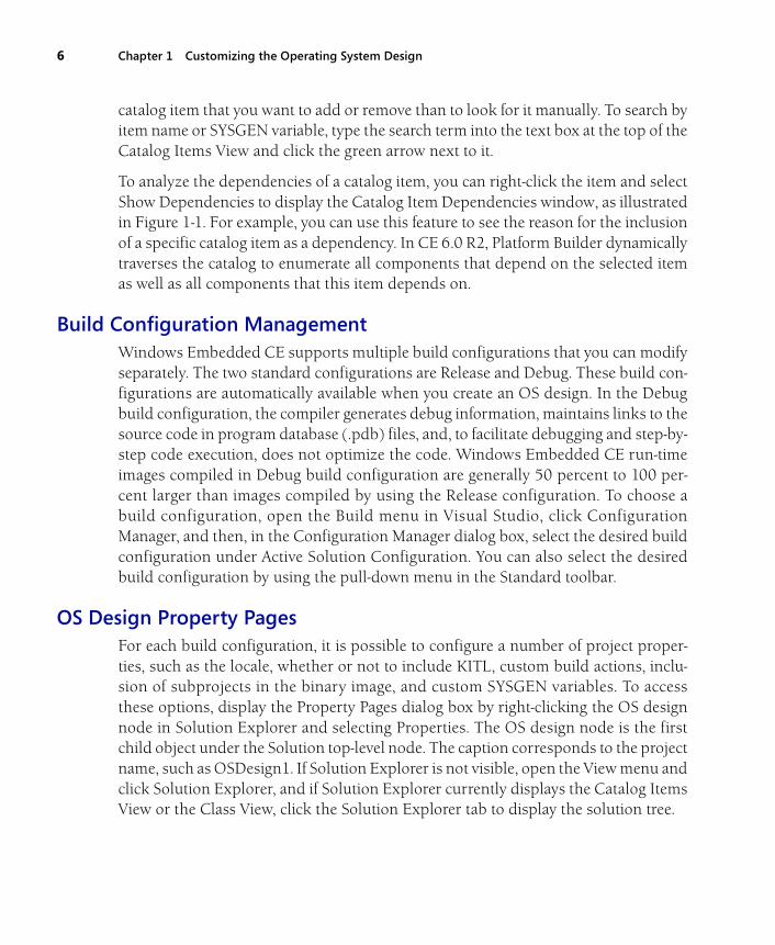
In the Catalog Items View, you can show all catalog components or enable a filter todisplay only selected catalog items. Click the downward arrow on the Filter button inthe top left corner of the Catalog Items View in Solution Explorer to apply a filter orselect the option All Catalog Items in the catalog to display the complete list of catalogitems.
Figure 1-1 Catalog Items View with the search box and Catalog Item Dependencies window
Provided that you know the name of the catalog item or the SYSGEN variable acomponent sets, you might find it more convenient and faster to search for the desired
6 Chapter 1 Customizing the Operating System Design
catalog item that you want to add or remove than to look for it manually. To search byitem name or SYSGEN variable, type the search term into the text box at the top of theCatalog Items View and click the green arrow next to it.
To analyze the dependencies of a catalog item, you can right-click the item and selectShow Dependencies to display the Catalog Item Dependencies window, as illustratedin Figure 1-1. For example, you can use this feature to see the reason for the inclusionof a specific catalog item as a dependency. In CE 6.0 R2, Platform Builder dynamicallytraverses the catalog to enumerate all components that depend on the selected itemas well as all components that this item depends on.
Build Configuration ManagementWindows Embedded CE supports multiple build configurations that you can modifyseparately. The two standard configurations are Release and Debug. These build con-figurations are automatically available when you create an OS design. In the Debugbuild configuration, the compiler generates debug information, maintains links to thesource code in program database (.pdb) files, and, to facilitate debugging and step-by-step code execution, does not optimize the code. Windows Embedded CE run-timeimages compiled in Debug build configuration are generally 50 percent to 100 per-cent larger than images compiled by using the Release configuration. To choose abuild configuration, open the Build menu in Visual Studio, click ConfigurationManager, and then, in the Configuration Manager dialog box, select the desired buildconfiguration under Active Solution Configuration. You can also select the desiredbuild configuration by using the pull-down menu in the Standard toolbar.
OS Design Property PagesFor each build configuration, it is possible to configure a number of project proper-ties, such as the locale, whether or not to include KITL, custom build actions, inclu-sion of subprojects in the binary image, and custom SYSGEN variables. To accessthese options, display the Property Pages dialog box by right-clicking the OS designnode in Solution Explorer and selecting Properties. The OS design node is the firstchild object under the Solution top-level node. The caption corresponds to the projectname, such as OSDesign1. If Solution Explorer is not visible, open the View menu andclick Solution Explorer, and if Solution Explorer currently displays the Catalog ItemsView or the Class View, click the Solution Explorer tab to display the solution tree.
Lesson 1: Creating and Customizing the Operating System Design 7
TIP Setting properties for multiple configurations
In the top left corner of the Property Pages dialog box, you can find a list box to select the buildconfiguration. Among other options, you can select All Configurations or Multiple Configura-tions. These options are useful if you want to set properties for multiple build configurations atthe same time.
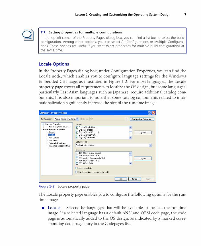
Locale OptionsIn the Property Pages dialog box, under Configuration Properties, you can find theLocale node, which enables you to configure language settings for the WindowsEmbedded CE image, as illustrated in Figure 1-2. For most languages, the Localeproperty page covers all requirements to localize the OS design, but some languages,particularly East Asian languages such as Japanese, require additional catalog com-ponents. It is also important to note that some catalog components related to inter-nationalization significantly increase the size of the run-time image.
Figure 1-2 Locale property page
The Locale property page enables you to configure the following options for the run-time image:
■ Locales Selects the languages that will be available to localize the run-timeimage. If a selected language has a default ANSI and OEM code page, the codepage is automatically added to the OS design, as indicated by a marked corre-sponding code page entry in the Codepages list.
8 Chapter 1 Customizing the Operating System Design
■ Default Locale Defines the default locale for the OS design. The defaultlanguage is English (United States), which uses the default code page 437(OEM-United States).
■ Code Pages Specifies the ANSI and OEM code pages that will be available in theOS design.
■ Localize The Build Instructs the build process to use localized string and imageresources. Platform Builder performs the localization of the OS design during themake image step of the OS design build process. Localized resource files are inte-grated inside the binary files for the common components, through res2exe.
■ Strict Localization Checking In The Build Causes the build process to fail iflocalization resources are missing, rather than just using the resources based onthe default locale.
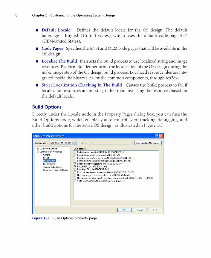
Build Options
Directly under the Locale node in the Property Pages dialog box, you can find theBuild Options node, which enables you to control event tracking, debugging, andother build options for the active OS design, as illustrated in Figure 1-3.
Figure 1-3 Build Options property page
Lesson 1: Creating and Customizing the Operating System Design 9
The Build Options property page enables you to configure the following options forthe run-time image:
■ Buffer Tracked Events In RAM Causes Platform Builder to includeOSCapture.exe in the CE image. Also enables logging of operating systemevents tracked by OSCapture.exe in RAM so they can be flushed to a file andviewed later.
■ Enable Eboot Space In Memory Enables the Ethernet boot loader (EBOOT) topass data to the Windows Embedded CE OS at start time.
■ Enable Event Tracking During Boot Enables CE event log data collection muchearlier during the start process than it would normally be collected otherwise. Ifyou activate this option, event tracking starts before most of the kernel and filesystem initialization is complete.
■ Enable Hardware-Assisted Debugging Support This is required for some third-party hardware debugging tools (JTAG probes compliant with exdi2).
■ Enable Kernel Debugger Enables the Windows Embedded CE debugger so youcan step through the code in the run-time image. Kernel debugging requires KITLto communicate with Platform Builder at run time.
■ Enable KITL Adds KITL to the run-time image. KITL is a useful debuggingfeature that enables developers to use the kernel debugger, interact with theremote device’s file system, registry, and other components, as well as run code.You should not include KITL in the final build of the operating system, because itintroduces overhead and wastes time during the start process trying to connect toa host computer.
■ Enable Profiling Enables the kernel profiler in the run-time image, which youcan use to collect and view timing and performance data. The kernel profiler is auseful tool for optimizing the performance of Windows Embedded CE on a targetdevice.
■ Flush Tracked Events To Release Directory Adds CeLogFlush.exe to the run-time image, which automatically flushes log data collected by OSCapture.exe tothe Celog.clg file in the release directory on the development computer.
■ Run-Time Image Can Be Larger Than 32 MB Enables you to build a larger-than-32-MB image. However, you should not use this option if you want to build animage larger than 64 MB. In this case, you must set an environment variable forthe appropriate size (such as IMGRAM128).

10 Chapter 1 Customizing the Operating System Design
■ Use Xcopy Instead Of Links To Populate Release Directory Creates actualcopies of the files by using xcopy rather than copylink. Copylink might onlycreate hard links to the files rather than copying them, and it requires the NTFSfile system on the development computer.
■ Write Run-Time Image To Flash Memory Instructs EBOOT to write therun-time image to the flash memory of the target device.
Environment OptionsThe Property Pages dialog box provides an Environment option to configure environ-ment variables that will be used during the build process. You can enable mostfeatures in Windows Embedded CE 6.0 R2 by using catalog components, but forsome options you need to set a SYSGEN variable so that Platform Builder compilesthe necessary code and includes it in the run-time image. Setting environmentvariables that influence the build process can be helpful when developing a BSP.Environment variables are accessible during the Windows Embedded CE buildprocess from the command line. You can also use environment variables to specifyflexible information in the sources, binary image builder (.bib), and registry (.reg) files.
TIP If it works in Debug but not in Release
If you can build a run-time image in the Debug configuration, but not in the Release configura-tion, display the Property Pages dialog box, select All Configurations from the Configuration listbox, and then select the Environment option to set the environment variables for both Debugand Release to the same values.
Advanced OS Design ConfigurationsThis section covers several advanced topics related to OS designs. Specifically, thissection explains how to support multiple platforms with the same OS design anddiscusses the file locations and file types that an OS design typically includes.
Associating an OS Design with Multiple Platforms
When creating a new OS design project by using the OS Design Wizard, you canselect one or more BSPs on the Board Support Packages wizard page. By associatingan OS design with multiple BSPs, you can generate separate run-time images withidentical content for multiple platforms. This is particularly useful in projects thatinclude multiple development teams, especially if the final target hardware is cur-rently not available. For example, you can generate a run-time image for an emulator-
Lesson 1: Creating and Customizing the Operating System Design 11
based platform so that the application development team can start before the finalhardware is available. In terms of OS functionality, the application development teamcan use the application programming interfaces (APIs) before the final target platformis available. The APIs will be included in the final target because the two run-timeimages share the same set of components and configuration settings.
You can also add support for multiple platforms to an OS design after the initial creation.All you need to do is select the corresponding check boxes under BSP in the Catalog ItemsView of Solution Explorer. Selecting a BSP automatically adds the additional platform tothe configuration for Release and Debug. You can then switch between the different plat-forms and build configurations by using Configuration Manager, which is available on theBuild menu in Visual Studio. However, it is necessary to run the entire build process,including the time-consuming SYSGEN phase, for each platform individually.
OS Design Paths and FilesIn order to use and redistribute your OS designs, you need to know exactly what filesconstitute an OS design and where they are located on your development computer.By default, you can find the OS designs in the %_WINCEROOT%\OSDesigns direc-tory. Each project corresponds to a separate child directory. OS designs typically cor-respond to the following file and directory structure:
■ <Solution Name> The parent directory that Visual Studio created for the project.
■ <Solution Name>.sln The Visual Studio solution (.sln) file to store settingsspecific to the OS design project. The file name is generally the same as that ofyour OS design.
■ <Solution Name>.suo The Visual Studio solution user options (.suo) file,which contains user-dependent information, such as the state of the SolutionExplorer views. The file name is generally the same as your OS design.
■ <OS Design Name> The parent directory for the remaining files included inthe OS design project.
● <OS Design Name>.pbxml Your OS design’s catalog file. This filecontains references to selected catalog components and all the settingsrelated to your OS design.
● Subprojects This directory includes a separate subfolder for eachsubproject created as part of the OS design.
● SDKs This directory includes the Software Development Kits (SDKs)created for the OS design.
12 Chapter 1 Customizing the Operating System Design
● Reldir This is the release directory. Platform Builder copies the files intothis directory during the process of creating the run-time image that canthen be downloaded to a target device.
● WinCE600 This is where files are copied after the Sysgen phase is com-plete, including resource files and configuration files for the current OSdesign.
Source Control Software ConsiderationsBasically, an OS design is a set of configuration files for Platform Builder to generatea Windows Embedded CE run-time image. If you are using source control software tocoordinate the work of your development team, you only have to store these configu-ration files in your source control repository. You do not need to include any files fromthe CESysgen folder (used during the build process of the run-time image) or Reldirdirectories, because they can be reconstituted on any workstation with PlatformBuilder and the BSP installed. Also, omit files ending in .user or .suo because those areuser-specific settings for the IDE, and omit .ncb files because these files only containIntelliSense® data.
Lesson SummaryPlatform Builder for Windows Embedded CE 6.0 R2 includes an OS Design Wizard tohelp you accomplish the basic OS design creation steps quickly and conveniently. Youcan select one or multiple BSPs to include all hardware-specific device drivers andutilities for your target platform and a design template with possible template variantsto include additional catalog items. After completing the OS Design Wizard, you canfurther customize the OS design. You can exclude unnecessary catalog items, includeadditional components, and configure project properties such as the Debug andRelease build options. In the Debug build configuration, Platform Builder includesdebug information in the run-time image, which leads to an increase of 50 percent to100 percent in comparison to Release builds. However, Debug builds facilitate debug-ging and step-by-step code execution during the development process. Because youcan configure Debug and Release build options separately, you might encounter asituation in which your OS design compiles in the Debug configuration but not in theRelease configuration. In this case, it can be helpful to set environment variables inboth Debug and Release to the same values. In order to distribute your OS designs,you need to locate the source f iles, which you can f ind by default in the%_WINCEROOT%\OSDesigns directory. You can use source control software tocoordinate the work of a development team.
Lesson 2: Configuring Windows Embedded CE Subprojects 13
Lesson 2: Configuring Windows Embedded CE SubprojectsA subproject is a Visual Studio project inserted into a parent project to include rela-tively independent components in an overall solution. In our case, the parent projecttypically corresponds to an OS design. Subprojects can take the following forms:
■ An application (managed or unmanaged).
■ A dynamic-link library (DLL).
■ A static library.
■ An empty project containing only configuration settings.
Subprojects are a good way to include a particular application, device driver, or othercode module in an OS design and to maintain this code and the OS design togetheras one solution.
After this lesson, you will be able to:
■ Create and configure subprojects.
■ Build and use subprojects.
Estimated lesson time: 20 minutes.
Windows Embedded Subprojects OverviewPlatform Builder for Windows Embedded CE enables you to create subprojects aspart of an OS design. Because subprojects are both modular and easily redistribut-able, they provide a convenient way to add applications, drivers, or other files to yourOS design without manually including them in the build tree as part of the BSP. Youcan also create subprojects for internal test applications and development tools tomake it quick and easy to build these tools and run them on a test device.
Types of Subprojects
Windows Embedded CE supports the following subproject types:
■ Applications Win32® applications with a graphical user interface (GUI),programmed in C or C++.
■ Console applications Win32 applications without a GUI, programmed in C orC++.
14 Chapter 1 Customizing the Operating System Design
■ Dynamic-link library (DLL) Drivers or other code libraries, loaded and used atrun time.
■ Static library Code modules in the form of library (.lib) files that you can linkto from other subprojects or export as part of the OS design’s SDK.
■ TUX dynamic-link library Windows Embedded CE custom test componentsfor the Microsoft Windows CE Test Kit (CETK), as explained in more detail inChapter 4.
Creating and Adding Subprojects to an OS DesignIt is straightforward to create a new subproject or add an existing project as a sub-project to an OS design. For the most part, you can use the Windows Embedded CESubproject Wizard to accomplish this task, which you can start by right-clicking theSubprojects folder in Solution Explorer and clicking Add New Subproject or Add Exist-ing Subproject. However, an understanding of the details, including the purpose of thevarious subproject types, the files and settings created by the CE Subproject Wizard,the build process, and customization possibilities for subprojects, is still helpful.
The CE Subproject Wizard creates a subfolder in the OS design folder, which containsall the required configuration files, including:
■ <Name>.pbpxml An XML-based file that contains metadata information aboutthe subproject. This file references the .bib, .reg, sources, and dirs files to build thesubproject.
■ <Name>.bib A binary image builder (.bib) file used during the makeimg step inthe build process to dictate files to include in the binary image.
■ <Name>.reg A registry file with settings to be included in the final run-timeimage.
■ Sources A Windows Embedded CE sources file. This is a makefile that containsbuild options to control the Windows Embedded CE build process.
■ Makefile A file used in association with the sources file in the Windows EmbeddedCE build process.
To make a copy of a subproject for later use, open your OSDesigns folder(%_WINCEROOT%\OSDesigns), and then open the solution folder for your OSdesign. The solution folder typically contains the <OS Design Name>.sln file and a foldernamed according to the OS design. Within this folder, you can find the definition file ofthe OS design <OS Design Name>.pbxml and several subdirectories. One of these sub-
Lesson 2: Configuring Windows Embedded CE Subprojects 15
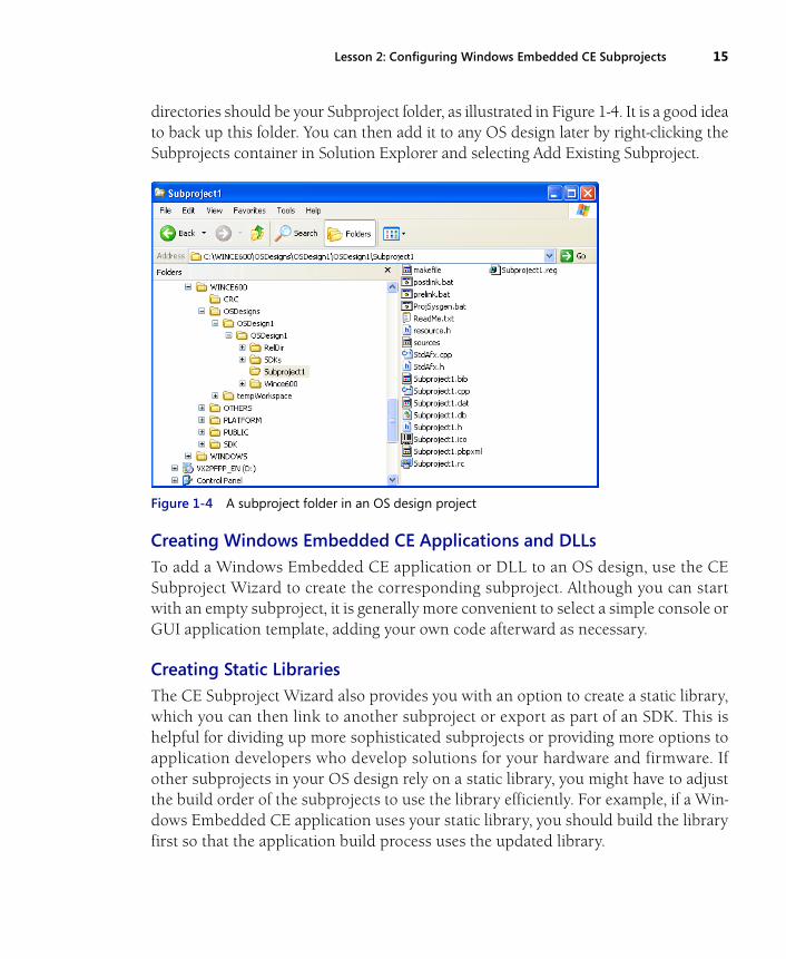
directories should be your Subproject folder, as illustrated in Figure 1-4. It is a good ideato back up this folder. You can then add it to any OS design later by right-clicking theSubprojects container in Solution Explorer and selecting Add Existing Subproject.
Figure 1-4 A subproject folder in an OS design project
Creating Windows Embedded CE Applications and DLLsTo add a Windows Embedded CE application or DLL to an OS design, use the CESubproject Wizard to create the corresponding subproject. Although you can startwith an empty subproject, it is generally more convenient to select a simple console orGUI application template, adding your own code afterward as necessary.
Creating Static LibrariesThe CE Subproject Wizard also provides you with an option to create a static library,which you can then link to another subproject or export as part of an SDK. This ishelpful for dividing up more sophisticated subprojects or providing more options toapplication developers who develop solutions for your hardware and firmware. Ifother subprojects in your OS design rely on a static library, you might have to adjustthe build order of the subprojects to use the library efficiently. For example, if a Win-dows Embedded CE application uses your static library, you should build the libraryfirst so that the application build process uses the updated library.
16 Chapter 1 Customizing the Operating System Design
Creating a Subproject to Add Files or Environment Variables to a Run-Time ImageSome subprojects do not necessarily include source code. For example, you can createan empty subproject by using the CE Subproject Wizard, modify the sources file, andset TARGETTYPE=NOTARGET to indicate you do not want to generate binary targetfiles. You can then add files to the run-time image by adding corresponding referencesto the subproject’s .bib file. You can also add registry settings to the subproject’s .regfile and you can add SYSGEN variables by editing the subproject’s Projsysgen.bat file.Although it is generally faster and more convenient to modify the .reg and .bib filesand project properties of the OS design directly, creating a subproject for this purposecan be advantageous if you are planning to reuse customizations in multiple OSdesigns in the future.
Configuring a SubprojectVisual Studio provides a number of options in the project properties that you can con-figure to customize the build process for subprojects. To configure these settings, dis-play the Property Pages dialog box for your OS design, as explained earlier in thischapter. You can then find the subproject properties under Subproject Image Settings.For each subproject added or created in the current OS design, you can configure thefollowing parameters:
■ Exclude From Build Activating this option excludes the subproject from thebuild process of the OS design, meaning the build engine does not process thesource files that belong to the selected subproject.
■ Exclude From Image Sometimes it can be time-consuming to deploy a run-timeimage when subprojects change. You have to disconnect from the target platform,rebuild the project, create a new image, reconnect to the target platform, anddownload the updated image every time a change is made with a subproject. Tosave time and effort when working on a subproject, you should exclude it fromthe run-time image by using the Exclude From Image option. In this case, youshould also create a way to update the file on the device at run time throughKITL, ActiveSync, or any other way you can transfer it to the device.
■ Always Build And Link As Debug By using this option, you build the subprojectin Debug build configuration while your current OS design build process usesthe Release configuration. In this way, you can debug the subproject code byusing the Kernel Debugger while the operating system is running in the Releaseversion (this option will not automatically enable the Kernel Debugger).
Lesson 2: Configuring Windows Embedded CE Subprojects 17
NOTE Exclusion from the run-time image
When you exclude a subproject from the run-time image, you implicitly exclude the subproject’sfiles from the Nk.bin file that is downloaded to the target device. Instead, Windows EmbeddedCE accesses the subproject’s files on an as-needed basis directly from the Release directory overKITL (when KITL is enabled). This means that you can modify the code in a driver or applicationsubproject without having to redeploy the run-time image. You should only need to verify thatthe remote device is not currently running the code, and then you can rebuild the code and runit again.
Lesson SummaryYou can use Windows Embedded CE subprojects to add applications, drivers, DLLs,and static libraries to an OS design, which is useful if you want to manage a complexWindows Embedded CE development project that includes a large number of appli-cations and components. For example, you can include a custom shell application ora device driver for a USB peripheral in the form of a subproject to an OS design, andthen have different development teams implement these components. You can alsouse Windows Embedded CE subprojects to add registry settings, environmentvariables, or specific files to various OS designs, such as the run-time files for the CoreConnectivity (CoreCon) interfaces or a test application. It is possible to back upsubprojects individually and add them as existing subprojects to future OS designs.
18 Chapter 1 Customizing the Operating System Design
Lesson 3: Cloning ComponentsPlatform Builder for Windows Embedded CE 6.0 R2 comes with public source codethat you can reuse and adapt for various purposes. You can analyze and modify thesource code for most of the components included in Windows Embedded CE, fromthe shell to the serial driver’s model device driver (MDD) layer. However, you mustnot modify the public source code directly. Instead, create a functional copy of thepublic code so that you can modify the desired components without affecting theoriginal Windows Embedded CE 6.0 R2 code base.
After this lesson, you will be able to:
■ Identify components to clone.
■ Clone an existing component.
Estimated lesson time: 15 minutes.
Public Tree Modification and Component CloningOnce you have discovered that the code you want to modify resides in the%_WINCEROOT%\Public folder, you might be tempted to modify this code in placeand then build it without moving it to another folder first. However, there are a num-ber of reasons not to modify the Public tree:
■ You have to back up the Public directory and maintain separate directory ver-s io ns fo r each o f yo ur OS d es ign pro jec t s , such as WINC E600\PUBLIC_Company1, WINCE600\PUBLIC_Company2, and WINCE600\PUBLIC_Backup.
■ Windows Embedded CE updates, patches provided by quick fix engineering(QFE), and service packs might overwrite or be incompatible with your modifi-cations.
■ Redistributing your code is difficult and error-prone.
■ Worst of all, when you change code in the Public directory tree, you have to spendup to three hours building the operating system. If you already know the CEbuild process so well that you can rebuild just your particular code withouthaving to rebuild the entire Public folder, you will also already know enough toclone the components.
Lesson 3: Cloning Components 19
CAUTION Public code modifications
Never modify the contents of the Public folder tree.
At a first glance, component cloning might seem like a lot of trouble, but it will saveyou development time and effort in the long run.
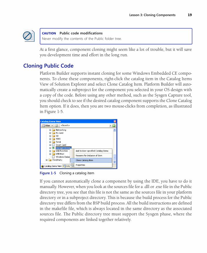
Cloning Public CodePlatform Builder supports instant cloning for some Windows Embedded CE compo-nents. To clone these components, right-click the catalog item in the Catalog ItemsView of Solution Explorer and select Clone Catalog Item. Platform Builder will auto-matically create a subproject for the component you selected in your OS design witha copy of the code. Before using any other method, such as the Sysgen Capture tool,you should check to see if the desired catalog component supports the Clone CatalogItem option. If it does, then you are two mouse-clicks from completion, as illustratedin Figure 1-5.
Figure 1-5 Cloning a catalog item
If you cannot automatically clone a component by using the IDE, you have to do itmanually. However, when you look at the sources file for a .dll or .exe file in the Publicdirectory tree, you see that this file is not the same as the sources file in your platformdirectory or in a subproject directory. This is because the build process for the Publicdirectory tree differs from the BSP build process. All the build instructions are definedin the makefile file, which is always located in the same directory as the associatedsources file. The Public directory tree must support the Sysgen phase, where therequired components are linked together relatively.
20 Chapter 1 Customizing the Operating System Design
Converting a component from the Public directory tree to a BSP component or a sub-project requires a number of steps, which are outlined in detail in the Platform Builderfor Microsoft Windows Embedded CE product documentation under “Using theSysgen Capture Tool” at http://msdn2.microsoft.com/en-us/library/aa924385.aspx.
Basically, you need to perform the following steps:
1. Copy the code of the desired Public component into a new directory.
2. Edit the sources file in the new directory and add the line RELEASETYPE=PLATFORM or change the value to PLATFORM if the line already exists so thatt he bu i ld eng in e p laces t he output f rom t h is bu i ld in to t he%_TARGETPLATROOT% folder.
3. Add WINCEOEM=1 to the sources file and build the component in the newdirectory. This might require further modifications to resolve all build errors.
4. Use the Sysgen Capture tool to create modular sources and dirs files.
5. Rename and use the files created by the Sysgen Capture tool along with a make-file to rebuild the new cloned module.
Once you apply all required modifications to the cloned component, you can modifyand redistribute it as easily as any other code.
Lesson SummaryWindows Embedded CE includes a Public directory tree with the source code formost of the CE components, but you should not modify the source code in the Publicdirectory tree directly. Instead, you should clone the items either automatically ormanually. Modifying the source code in the Public directory tree causes more troublenow as well as in the future unless you already know the build system very well, inwhich case you already know all the good reasons why you should use the cloningmethod.
Lesson 4: Managing Catalog Items 21
Lesson 4: Managing Catalog ItemsOne of Windows Embedded CE’s most useful features is its catalog system. By usingthe catalog, developers can quickly and conveniently customize the WindowsEmbedded CE firmware to suit their needs. If you create a custom catalog item foreach of your components, you can facilitate the installation and configuration of yourcomponents. This is a differentiating factor between ad-hoc and professionalWindows Embedded CE solutions. For ad-hoc solutions, it might be sufficient to pro-vide basic installation notes and a list of required SYSGEN variables, but professionalsoftware should include catalog items with proper values for SYSGEN variables andconfiguration settings.
After this lesson, you will be able to:
■ Customize the content of the catalog.
■ Add a new component entry to a BSP catalog.
Estimated lesson time: 20 minutes.
Catalog Files OverviewThe Windows Embedded CE catalog uses files in Extensible Markup Language(XML) format with a .pbcxml file-name extension. The catalog includes a largenumber of .pbcxml files, located inside the WINCEROOT directory. Platform Builderautomatically enumerates these files to generate the Catalog Items View in SolutionExplorer.
Platform Builder parses the following directories to enumerate catalog items:
■ Public catalog files %_WINCEROOT%\Public\<any subdirectory>\Catalog\
■ BSP catalog files %_WINCEROOT%\Platform\<any subdirectory>\Catalog\
■ Third-party catalog files %_WINCEROOT%\3rdParty\<any subdirectory>\Catalog\
■ Common system-on-chip (SOC) files %_WINCEROOT%\Platform\Common\Src\soc\<any subdirectory>\Catalog\
22 Chapter 1 Customizing the Operating System Design
NOTE 3rdParty folder
The 3rdParty folder usually contains standalone applications or source applications that can beincluded and distributed as part of an OS design. By enumerating the .pbcxml files in the3rdParty folder, Platform Builder provides a way to add entries to the Catalog Items View forthose components.
Creating and Modifying Catalog EntriesTo add a new catalog item to the Windows Embedded CE catalog, you can create acopy of an existing catalog file (.pbcxml file) and then edit the file content by usingthe Catalog Editor provided with Platform Builder. You can also create a new catalogfile in Platform Builder if you open the File menu in Visual Studio, point to New, andthen select File. In the New File dialog box, under Platform Builder for CE 6.0 R2,select Platform Builder Catalog File, and then click Open.
NOTE Editing catalog files
Always edit catalog files by using the Catalog Editor provided with Platform Builder. There are nosettings that require you to work with a text editor such as Notepad. Opening and editing cata-log files manually outside of Platform Builder is unnecessarily time-consuming.
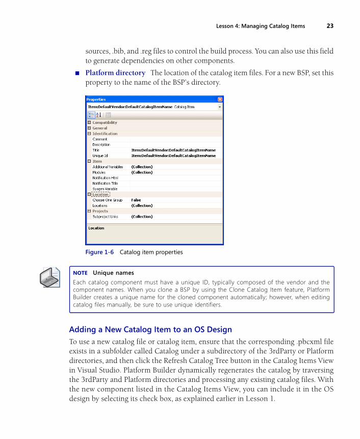
Catalog Entry PropertiesEach catalog entry has a number of properties that you can modify in PlatformBuilder, as illustrated in Figure 1-6. The most important properties include the follow-ing:
■ Unique Id A unique identifier string.
■ Name The name of the catalog component as it appears in the Catalog ItemsView.
■ Description An expanded description of the component, which appears whenthe user hovers the mouse pointer over the catalog item for several seconds.
■ Modules A list of files that belong to this catalog component.
■ Sysgen variable An environment variable for the catalog item. If your catalogcomponent sets a SYSGEN variable, this is where to put it.
■ Additional Variables A collection of additional environment variables for thecatalog item. This is possibly the most important part of the catalog componentin a BSP, because this field enables you to set environment variables used in
Lesson 4: Managing Catalog Items 23
sources, .bib, and .reg files to control the build process. You can also use this fieldto generate dependencies on other components.
■ Platform directory The location of the catalog item files. For a new BSP, set thisproperty to the name of the BSP’s directory.
Figure 1-6 Catalog item properties
NOTE Unique names
Each catalog component must have a unique ID, typically composed of the vendor and thecomponent names. When you clone a BSP by using the Clone Catalog Item feature, PlatformBuilder creates a unique name for the cloned component automatically; however, when editingcatalog files manually, be sure to use unique identifiers.
Adding a New Catalog Item to an OS Design
To use a new catalog file or catalog item, ensure that the corresponding .pbcxml fileexists in a subfolder called Catalog under a subdirectory of the 3rdParty or Platformdirectories, and then click the Refresh Catalog Tree button in the Catalog Items Viewin Visual Studio. Platform Builder dynamically regenerates the catalog by traversingthe 3rdParty and Platform directories and processing any existing catalog files. Withthe new component listed in the Catalog Items View, you can include it in the OSdesign by selecting its check box, as explained earlier in Lesson 1.
24 Chapter 1 Customizing the Operating System Design
Using a Catalog Item for BSP DevelopmentNow that you have added your new catalog component and learned how to set item-specific environment variables, you can use this technique to include the componentin a BSP, set C/C++ build directives, and modify system registry settings in the run-time image. When other developers using this BSP select your catalog item in an OSdesign project, they will implicitly use the settings you specified. To include a catalogcomponent in a BSP, you need to edit the BSP’s Platform.bib file and add a conditionalstatement based on your settings. You can choose to include a component if a variableis or isn’t defined by using if-else statements. Note that it might be necessary to runthe Rebuild Current BSP and Subprojects command, which you can find in VisualStudio on the Build menu, under Advanced Build Commands, for changes to the .biband .reg files to take effect. Chapter 2 covers the Rebuild Current BSP and Subprojectscommand in more detail.
To set a C/C++ directive based on an environment variable that you specified in thecatalog item’s properties, you can use a conditional statement in the sources file basedon the variable and add a CDEFINES entry. You should generally try to avoid settingC/C++ build directives based on catalog item properties, as this approach will make itdifficult to distribute a binary version of your BSP in the future.
You can also change entries in the system registry by using conditional statements.You only need to edit the .reg files to include or exclude certain registry files relatedto the new component.
Exporting a Catalog Item from the CatalogSome catalog items do not support direct cloning. To clone these components, youmust create either a new catalog file, if you are creating a new entry under the 3rdPartyfolder, or a new entry in a BSP’s existing catalog file. In any case, you should verify thatthe original values for all SYSGEN and additional environment variables are pre-served. Do not forget to change the ID, because each item in the catalog must have aunique ID, as mentioned earlier in this lesson.
Catalog Component DependenciesThe catalog in Platform Builder for Windows Embedded CE 6.0 R2 supports compo-nent dependencies. To specify that a component is dependent on another compo-nent, you must set the SYSGEN or Additional Variables field for the component of thecatalog item, and then include this value in the form of an additional environmentvariable in the dependent component. For example, if you have catalog components
Lesson 4: Managing Catalog Items 25
in your BSP for both a display driver and a backlight driver for the display, you can setthe Additional Variables field for the display driver to BSP_DISPLAY and the Addi-tional Variables field for the backlight driver to BSP_BACKLIGHT. If you now wantthe display driver to be dependent on the backlight driver, you can edit the catalogentry for BSP_DISPLAY in the Catalog Editor and add BSP_BACKLIGHT to the addi-tional environment variables. Then, whenever you include the display driver in an OSdesign, Platform Builder automatically includes the backlight driver as well. The Cat-alog Items View will show the check box of the backlight driver with a green squareto indicate that this component is included as a dependency of the display driver.
Lesson SummaryPlatform Builder for Windows Embedded CE 6.0 R2 comes with a file-based catalogsystem that you can use to contain your own catalog items by including them in sep-arate catalog files in the Platform or 3rdParty directory within the %_WINCEROOT%directory tree. The file format of catalog files is XML and the file-name extension is.pbcxml. Platform Builder automatically enumerates the .pbcxml files when you startVisual Studio or refresh the Catalog Items View in Solution Explorer. To add a newcatalog item to the Windows Embedded CE catalog, you can start with a new catalogfile or create a copy of an existing catalog item and then edit the file content by usingthe Catalog Editor. There is no need to edit .pbcxml files by using a text editor, suchas Notepad, because all settings are available directly within Platform Builder. Amongother things, you can specify SYSGEN and additional environment variables for con-ditional C/C++ build directives, registry modifications, and dependency definitions.
26 Chapter 1 Customizing the Operating System Design
Lesson 5: Generating a Software Development KitDevelopers who want to create applications for a target device require a SoftwareDevelopment Kit (SDK). An SDK will automatically correspond to your OS design sothat the developers can only use those features that are actually available. The SDKincludes features that are present in the OS design so that application developers donot accidentally create code that fails to run at run time due to an unsupported API.
After this lesson, you will be able to:
■ Identify the purpose of an SDK.
■ Generate an SDK.
■ Localize SDK files on your hard drive.
■ Use an SDK.
Estimated lesson time: 20 minutes.
Software Development Kit OverviewIn order to compile and create valid applications for your OS design, developers needto include the necessary header files and link to the correct libraries in their develop-ment projects. You must ensure that the SDK for your OS design contains all requiredheader files and libraries, including headers and libraries for any custom componentsyou want to provide to application developers. Platform Builder for Windows Embed-ded CE 6.0 R2 enables you to create SDKs for your OS designs by exporting all therequired header files and libraries.
SDK GenerationIt is generally the task of the OS design creator to generate and distribute customizedSDKs. Platform Builder provides an SDK export feature for this purpose. The SDKexport feature creates the customized SDK for your OS design, along with a .msi filethat includes the SDK Setup Wizard.
Configuring and Generating an SDK
To create and configure an SDK by using the SDK export feature of Platform Builder,follow these steps:
Lesson 5: Generating a Software Development Kit 27
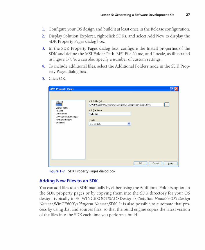
1. Configure your OS design and build it at least once in the Release configuration.
2. Display Solution Explorer, right-click SDKs, and select Add New to display theSDK Property Pages dialog box.
3. In the SDK Property Pages dialog box, configure the Install properties of theSDK and define the MSI Folder Path, MSI File Name, and Locale, as illustratedin Figure 1-7. You can also specify a number of custom settings.
4. To include additional files, select the Additional Folders node in the SDK Prop-erty Pages dialog box.
5. Click OK.
Figure 1-7 SDK Property Pages dialog box
Adding New Files to an SDKYou can add files to an SDK manually by either using the Additional Folders option inthe SDK property pages or by copying them into the SDK directory for your OSdesign, typically in %_WINCEROOT%\OSDesigns\<Solution Name>\<OS DesignName>\WinCE600\<Platform Name>\SDK. It is also possible to automate that pro-cess by using .bat and sources files, so that the build engine copies the latest versionof the files into the SDK each time you perform a build.
28 Chapter 1 Customizing the Operating System Design
Make sure you copy the files into the following SDK subdirectories:
■ Inc Contains the header files included in the SDK.
■ Lib\<Processor Type>\<Build Type> Contains the libraries included in the SDK.
Installing an SDKAfter completing the SDK build process, you can find the .msi file in the SDK subdi-rectory of your OS design folder. This is typically %_WINCEROOT%\OSDesigns\<Solution Name>\<OS Design Name>\SDKs\SDK1\MSI\<SDK Name>.msi. You canfreely redistribute this MSI according to your licensing agreements for PlatformBuilder and any third-party components included.
You can install this MSI package on any computer with Visual Studio 2005 and use itto develop Windows Embedded CE applications for your target device. On a com-puter with the SDK installed, you can find the files under %PROGRAMFILES%\Windows Embedded CE Tools\WCE600.
Lesson SummaryWindows Embedded CE 6.0 R2 is a componentized operating system, which impliesthat application developers require a customized SDK that corresponds to your OSdesign in order to develop applications that will work on your target device. The cus-tom SDK should not only include the required Windows Embedded CE components,but also the headers and libraries for any custom components that you included inthe OS design, to avoid problems due to missing files or libraries at build and runtime. Platform Builder provides an SDK export feature to generate SDKs and to createan MSI package for convenient SDK deployment on application development com-puters by means of an SDK Setup Wizard.
Lab 1: Creating, Configuring, and Building an OS Design 29
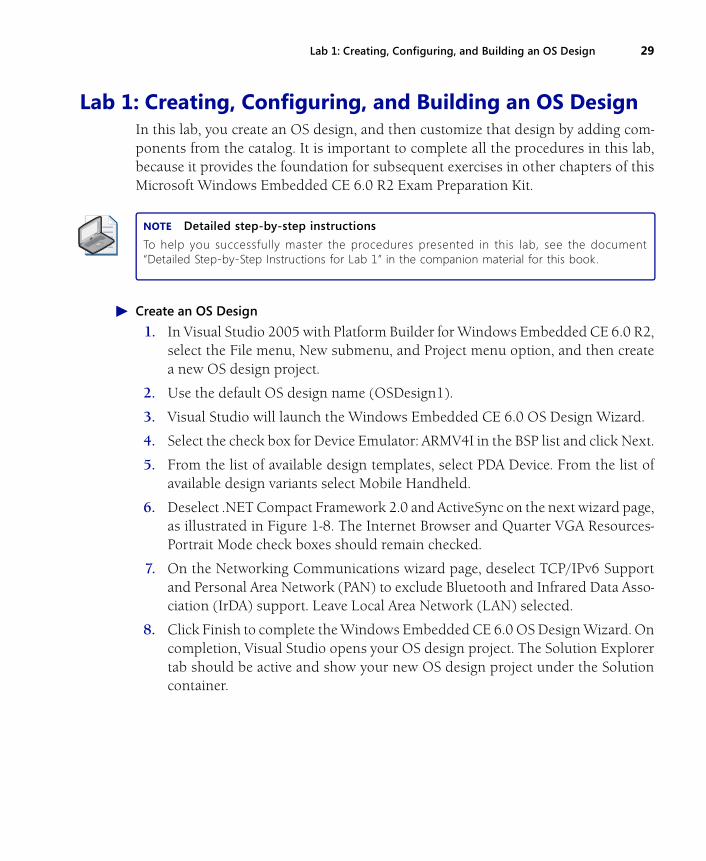
Lab 1: Creating, Configuring, and Building an OS Design In this lab, you create an OS design, and then customize that design by adding com-ponents from the catalog. It is important to complete all the procedures in this lab,because it provides the foundation for subsequent exercises in other chapters of thisMicrosoft Windows Embedded CE 6.0 R2 Exam Preparation Kit.
NOTE Detailed step-by-step instructions
To help you successfully master the procedures presented in this lab, see the document“Detailed Step-by-Step Instructions for Lab 1” in the companion material for this book.
� Create an OS Design
1. In Visual Studio 2005 with Platform Builder for Windows Embedded CE 6.0 R2,select the File menu, New submenu, and Project menu option, and then createa new OS design project.
2. Use the default OS design name (OSDesign1).
3. Visual Studio will launch the Windows Embedded CE 6.0 OS Design Wizard.
4. Select the check box for Device Emulator: ARMV4I in the BSP list and click Next.
5. From the list of available design templates, select PDA Device. From the list ofavailable design variants select Mobile Handheld.
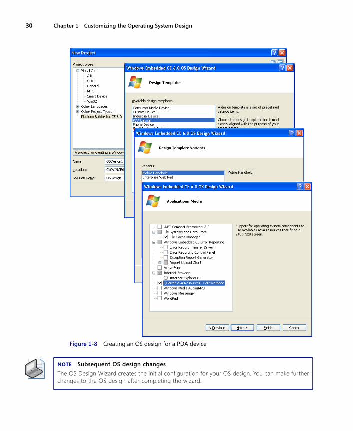
6. Deselect .NET Compact Framework 2.0 and ActiveSync on the next wizard page,as illustrated in Figure 1-8. The Internet Browser and Quarter VGA Resources-Portrait Mode check boxes should remain checked.
7. On the Networking Communications wizard page, deselect TCP/IPv6 Supportand Personal Area Network (PAN) to exclude Bluetooth and Infrared Data Asso-ciation (IrDA) support. Leave Local Area Network (LAN) selected.
8. Click Finish to complete the Windows Embedded CE 6.0 OS Design Wizard. Oncompletion, Visual Studio opens your OS design project. The Solution Explorertab should be active and show your new OS design project under the Solutioncontainer.
30 Chapter 1 Customizing the Operating System Design
Figure 1-8 Creating an OS design for a PDA device
NOTE Subsequent OS design changes
The OS Design Wizard creates the initial configuration for your OS design. You can make furtherchanges to the OS design after completing the wizard.

Lab 1: Creating, Configuring, and Building an OS Design 31
� Inspect the OS Catalog
1. In Visual Studio, locate Solution Explorer and click the Catalog Items View tab.
2. Expand the individual container nodes to analyze the selected check boxes andicons in the catalog. Check boxes with a green check mark indicate items specif-ically added as a part of the OS design. Check boxes with a green square indicateitems that are part of the OS design due to dependencies. Selection boxes thatare not marked indicate items that are not included in the OS design but areavailable to be added.
3. Locate a catalog item with a green square in its check box.
4. Right-click this catalog item and choose Reasons For Inclusion Of Item. TheRemove Dependent Catalog Item dialog box displays the catalog items thatcaused Platform Builder to include the selected catalog item in the OS design, asillustrated in Figure 1-9.
5. Expand the Core OS | CEBASE | Applications – End User | ActiveSync node inthe catalog.
6. Right-click either of the ActiveSync system cpl items and select Display In Solu-tion View. The view changes to the Solution Explorer tab to display the sub-project containing the ActiveSync component. This is a great way to navigatethrough the source code that comes with Windows Embedded CE 6.0.
Figure 1-9 Reason for including a catalog item as a dependency

32 Chapter 1 Customizing the Operating System Design
� Add Support for the Internet Explorer 6.0 Sample Browser Catalog Item
1. Select the Catalog Items View tab to display the OS design catalog. Verify thatthe filtering option is set to All Catalog Items In Catalog.
2. In the Search text box to the right of the Catalog Items View Filter button, typeInternet Explorer 6.0 Sample and press Enter or click the green arrow.
3. Verify that the search locates the Internet Explorer 6.0 Sample Browser catalogitem. Select the corresponding check box to include this catalog item in the OSdesign, as illustrated in Figure 1-10.
Figure 1-10 Including the Internet Explorer 6.0 Sample Browser catalog item in an OS design
� Add Support for Managed Code Development to Your OS Design
1. In the Search text box, type ipconfig and press Enter.
2. Verify that the search locates the Network Utilities (IpConfig, Ping, Route) cata-log item.
3. Add the Network Utilities (IpConfig, Ping, Route) catalog item to your OSdesign by selecting the corresponding check box.
4. In the Search text box, type wceload and press Enter.
5. Verify that the search locates the CAB File Installer/Uninstaller catalog item. Thesearch can find this catalog item because the value of its SYSGEN variable iswceload.
Lab 1: Creating, Configuring, and Building an OS Design 33
6. Add the Cab File Installer/Uninstaller catalog item to your OS design.
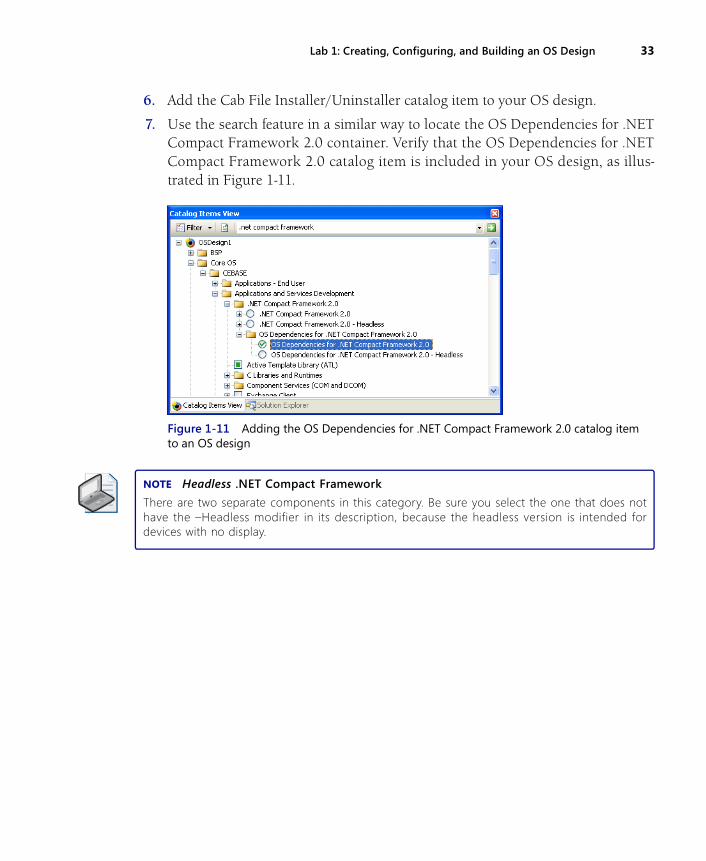
7. Use the search feature in a similar way to locate the OS Dependencies for .NETCompact Framework 2.0 container. Verify that the OS Dependencies for .NETCompact Framework 2.0 catalog item is included in your OS design, as illus-trated in Figure 1-11.
Figure 1-11 Adding the OS Dependencies for .NET Compact Framework 2.0 catalog item to an OS design
NOTE Headless .NET Compact Framework
There are two separate components in this category. Be sure you select the one that does nothave the –Headless modifier in its description, because the headless version is intended fordevices with no display.
34 Chapter 1 Review
Chapter ReviewIn order to deploy Microsoft Windows Embedded CE 6.0 R2 on a target device, youmust create an OS design that includes the necessary operating system (OS) compo-nents, features, drivers, and configuration settings. You can then use Platform Builderto build the corresponding run-time image for deployment. The most important tasksyou must accomplish to create a customized OS design that suits your requirementsinclude:
■ Creating an OS design project in Visual Studio by using the OS Design Wizard.
■ Adding and removing components from the OS manually and through depen-dencies.
■ Setting environment and SYSGEN variables through the Catalog Editor.
■ Configuring regional settings for localization of the OS design.
■ Cloning components from the catalog either automatically by clicking CloneCatalog Item or manually by using the Sysgen Capture tool.
■ Exporting a custom SDK for your OS design to facilitate application developmentfor your target device.
Key TermsDo you know what these key terms mean? You can check your answers by looking upthe terms in the glossary at the end of the book.
■ OS design
■ Component
■ SYSGEN variable
■ Environment Variable
■ Software Development Kit
Suggested PracticeTo help you successfully master the exam objectives presented in this chapter,complete the following tasks:
Chapter 1 Review 35
Create a Custom OS DesignBy using the OS Design Wizard, create an OS design based on the Device Emulator:ARMV4I BSP and the Custom Device design template. Perform the following tasksafter OS design creation:
■ Add the .NET Compact Framework 2.0 Add this catalog item by using thesearch feature in the Catalog Items View.
■ Localize your run-time image Display the OS Design property pages and local-ize the OS design for the French language.
Generate and Test an SDKBased on the OS design generated during Lab 1, perform the following tasks:
■ Build and generate the binary image Build and generate the binary image forthe OS design generated in the Release build configuration.
■ Create and install the SDK Verify that the build process completes successfully,and then create a new SDK, build it, and install it on an application developmentcomputer.
■ Use the SDK Use another instance of Visual Studio and create a Win32 SmartDevice application. Use your custom SDK as the reference SDK for the projectand build the application.


