R. & M. No. 3264 MINISTRY OF AVIATION AERONAUTICAL RESEARCH COUNCIL REPORTS AND MEMORANDA Wind Tunnel Tests andTheoretical Investigations on the Effect of a Localised Mass on the Flutter of a Delta Wing with Fixed Root By G. F. DONNO, B.Sc.(Eng.), A.F.R.Ae.S. DESIGN DEPARTMENT, WESTLAND AIRCRAFT LTD., SAUNDERS-RoE DIVISION. LONDON: HER MAJESTY'S STATIONERY OFFICE 19 62 P RIC E [, 17 s. 6 d. NET
Transcript
R. & M. No. 3264
MINISTRY OF AVIATION
AERONAUTICAL RESEARCH COUNCIL
REPORTS AND MEMORANDA
Wind Tunnel Tests and Theoretical Investigationson the Effect of a Localised Mass on the Flutter
of a Delta Wing with Fixed RootBy G. F. DONNO, B.Sc.(Eng.), A.F.R.Ae.S.
Wind Tunnel Tests and Theoretical Investigationson the' Effect of a Localised Mass on the Flutter
of a Delta Wing with Fixed RootBy G. F. DONNa
Reports and Memoranda No. 3264*
March, I959
Summary.-Wind tunnel tests and theoretical investigations have been carried out to study the effectof a localised mass on the flutter characteristics of a delta wing. The experimental work covered a wide rangeof spanwise and chordwise positions of the mass e.g., variation of the magnitude and radius of gyration ofthe mass itself, and the effect of the stiffness distribution of the wing. The theoretical work was more limitedin its scope and was primarily intended to investigate the reliability of the theoretical approach to this kindof problem.
These investigations have shown that the flutter characteristics of a delta wing carrying a localised massare primarily dependent oil' the location of the mass, its magnitude and the stiffness distribution of the wingitself. The flutter speed with a localised mass judiciously placed may be from three to four times that obtainedwith the same mass in a bad position.
A localised mass in the region around the structural axis generally has an adverse effect on the fluttercharacteristics, while locations well aft, towards the trailing edge, are usually favourable. Particularly highflutter speeds are often associated with a localised mass close to the leading edge, but some caution is necessary,especially around the mid-span position, as the flutter characteristics in this region are very sensitive tovariations in actual mass.
A fair measure of success was obtained in the theoretical investigations, the calculated flutter characteristicsbeing in reasonable agreement with experimental results in most cases. Calculations based on resonancetest modes gave remarkably good results in certain cases, but in general, this method showed only a slightsuperiority over the arbitrary mode approach.
1. Introduction. Earlier work carried out in connection with the design of the SR.53 had shown
that the fitting of a considerable localised mass to a delta wing could produce changes in the flutter
characteristics which are of the same order of magnitude as those which occur in the case of wings
of higher aspect ratio. The work on the SR.53, however, was restricted to a study of the effects of a
localised mass at the wing tip, whereas the present investigations have covered variations in both
the spanwise and chordwise location of a localised mass, together with variations in its magnitude
and radius of gyration. The effects of a variation in the wing stiffness distribution, corresponding to
the effect of a large cut-out, e.g., undercarriage bay, have also been investigated.
Both wind tunnel flutter tests and theoretical investigations were carried out in the course of theprogramme. The former covered a wide range of parameter variations and a total of approximatelyone hundred and fifty separate cases were investigated. It was impracticable, of course, to coveranything like this range in the course of the theoretical work and ten representative cases weretherefore selected for flutter calculations. These ten cases were investigated using both arbitrarymodes and resonance modes, the latter being obtained from tests on the model.
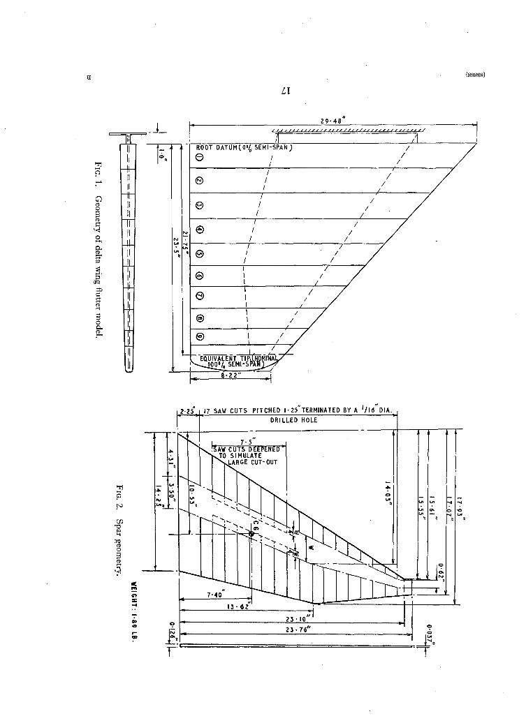
2. Description of the Model. The model wing used for these investigations was of the now familiarsegmented construction, comprising an aluminium alloy plate spar carrying a number of wooden
box segments having the required aerofoil shape.
The spar was adapted from the taper-machined plate spar used in the SR.53 wing flutter model.
As the latter had a high 'bare wing' flutter speed, however, it was necessary to reduce the stiffness
of the spar quite drastically in order to permit investigation of those cases in which the localised mass
increases the flutter speed above that of the bare wing. This was achieved by means of saw-cutsfrom the front and rear edges of the spar, thereby reducing its effective width and stiffness butwithout appreciably reducing its weight or interfering with the arrangements for attaching the boxsegments. (See Fig. 2.) For the first series of tests (i.e., for a wing without a cut-out) the depth ofthese saw-cuts was graduated so as to give a fairly smooth grading of stiffness from root to tip.To simulate the cut-out for the second part of the programme, the cuts in the inner portion of thewing were increased in depth so as to reduce the effective width of the spar to about one half itsprevious value. (See Fig. 2.)
The root of the spar was clamped between two substantial angle section members so as to provide a'fixed root' when set up in the wind tunnel for flutter tests or bolted to a rig for resonance testing.
The aerodynamic form of the flutter model was made up of nine box segments and a tip fairing.These were constructed of balsa and thin plywood and carried a small amount of lead ballast tosimulate the inertia properties of a typical aircraft wing of this type. To prevent this shell from
making any significant contribution to the overall stiffness of the wing, each segment was bolted to
the spar at one spanwise position only, and for the same reason the gaps between the segments werenot sealed. Very thin rubber sealing strips were originally fitted to the SR.53 flutter model but it
was found that, at the tunnel speeds involved, their removal made no sensible difference to the
flutter characteristics. The geometry of the assembled wing is shown in Fig. 1, and the leadingparticulars are as follows:
Semi-span (overall)
Root Chord
Tip Chord (Projected)
L.E. Sweepback
T.E. Sweepback
Thickness/Chord Ratio
23·5 in.
29·5 in.
8·22 in.
42 deg
odeg
6 per cent
3. Stiffness and Resonance Tests. 3.1. Stiffness Tests. Torsional and flexural stiffness testswere carried out to provide basic structural data for arbitrary mode flutter calculations. The modelwas tested when it was assembled for the first series of tests and again after the spar had beenmodified to simulate the effect of a large cut-out.
2
3.2. Resonance Tests. Resonance tests were carried out to obtain the modes for use in thetheoretical flutter investigations. Of the total of ten cases investigated, seven were for the originalwing and three for the wing with its stiffness modified to simulate a large cut-out. Details of thesecases are given below in Section 5 'Theoretical Investigations'.
The wing was rigidly mounted at the root and the localised masses were applied through theremote loading rig as in wind tunnel tests. Excitation in these tests was provided by means of avariable eccentric driven by a d.c, electric motor operated as part of a Ward-Leonard set. Theactual connection on to the model was made with a length of rubber shock-absorber cord.
Because of the extreme flexibility of the model, no method for determining vibration amplitudesthat involved any mechanical connection to the model could be considered. Fortunately, however,a photographic method, originally developed in connection with work on the SR.53 flutter modelswas available. A series of small white markers or 'flags', were fitted along the leading and trailingedges of the model and a white grid was constructed to cover the whole of one surface of the wing.By making time exposures with the model resonating it was possible to derive the amplitude ofvibration and the location of the nodal lines.
4. Wind Tunnel Tests. Experimental flutter investigations were carried out in a low speed windtunnel with a 6 ft by 4 ft elliptical open working section. The maximum speed obtainable was
approximately 120 ft/sec.The model was mounted vertically in the tunnel to avoid large static displacements under gravity
(its stiffness being very low) and a plate incorporated in the root mounting acted as a reflector tosimulate symmetric flow conditions.
The localised masses were applied to the wing through a remote loading rig of the type describedin Ref. 1. With this arrangement there is less possibility of the results being influenced by aerodynamiceffects than with localised masses of different shapes and sizes fitted directly to the wings. Otheradvantages over the fitting of large concentrated weights to the wing are that large gravitationalforces on the model are avoided, while the loading platform of the rig makes a good safety devicethat can be held should the flutter motion become too violent.
Flutter frequencies were obtained from analysis of cine-film records of the flutter motion. By thismeans it was also possible to study the motion in detail without risking loss of the model by prolongedrunning above the flutter speed.
(A detailed account of these wind tunnel flutter tests is given in Appendix 1.)
4.1. Programme of Flutter Tests. 4.1.1. Tests on the model with original spar (i.e., no cut-out).After an initial run to determine the flutter characteristics of the bare wing, the following series ofinvestigations were carried out to determine the effect of various parameters relating to the localisedmass:
(a) Detailed investigation of the effect of spanwise and chordwise location of the localised mass.Flutter characteristics were determined with the mass located at each of six evenly spacedstations, across the chord from L.E. to T.E., at 25, SO, 75 and 100 per cent of the semi-span.
This investigation was carried out in full for three different localised masses, representing40, 70 and 100 per cent of the bare wing weight. The radius of gyration of the localisedmass was kept constant throughout, at 30 per cent of the wing mean chord. A more detailedinvestigation of the effects of varying the magnitude of the localised mass at four selectedstations was carried out later. (See paragraph (c) below.)
3(83868) A2
(b) Investigations of the effect of variation of the radius ofgyration without change of mass. In thispart of the programme, the localised mass was kept constant and equal to the weight of thebare wing, while the radius of gyration was increased in five equal steps from 20 per centto 40 per cent of the wing mean chord.
This procedure was repeated for four different positions of the localised mass, namely,
wing-tip L.E., wing-tip T.E., 50 per cent semi-span L.E. and 50 per cent semi-span T.E.
(c) Investigation of the effect of variation of mass without change of radius ofgyration. The tests
already noted in paragraph (a) above, involved the investigation of broad variations of this
kind, but for certain selected locations the effect of variation of the localised mass was
investigated in greater detail. The radius of gyration of the localised mass was kept constantat 30 per cent of the mean chord while the mass was increased in five equal increments from
40 per cent to 100 per cent of the bare wing weight.The stations selected for these investigations were the same as those chosen in the work
described in paragraph (b).
4.1.2. Tests on the model with a modified spar, simulating a large cut-out. The programme oftests carried out on the model after modification was not so extensive as in the previous seriesdescribed above.
Following an initial test to determine the flutter characteristics of the bare wing, the effects of thespanwise and chordwise position of the localised mass were investigated. The investigations wereessentially similar to those described in paragraph (a) of Section 3.1.1, but only two sections, atmid-span and the wing-tip, were considered.
5. Theoretical Investigations. Theoretical investigations on the flutter model have covered tenselected cases, comprising:
(a) Investigation on model wing with original spar (i.e., no cut-out).
Case 1. Bare wing with no localised mass.
Case 2. Localised mass (70 per cent of bare wing weight) at 75 per cent semi-span on L.E.----
Case 3. Localised mass (70 per cent of bare wing weight) at 75 per cent semi-span on.---
40 per cent chord line.
Case 4. Localised mass '(70 per cent of bare wing weight) at 75 per cent semi-span on T.E.----
Case 5. Localised mass (70 per cent of bare wing weight) at wing-tip on L.E.---Case 6. Localised mass (70 per cent of bare wing weight) at wing-tip on 40 per cent chord
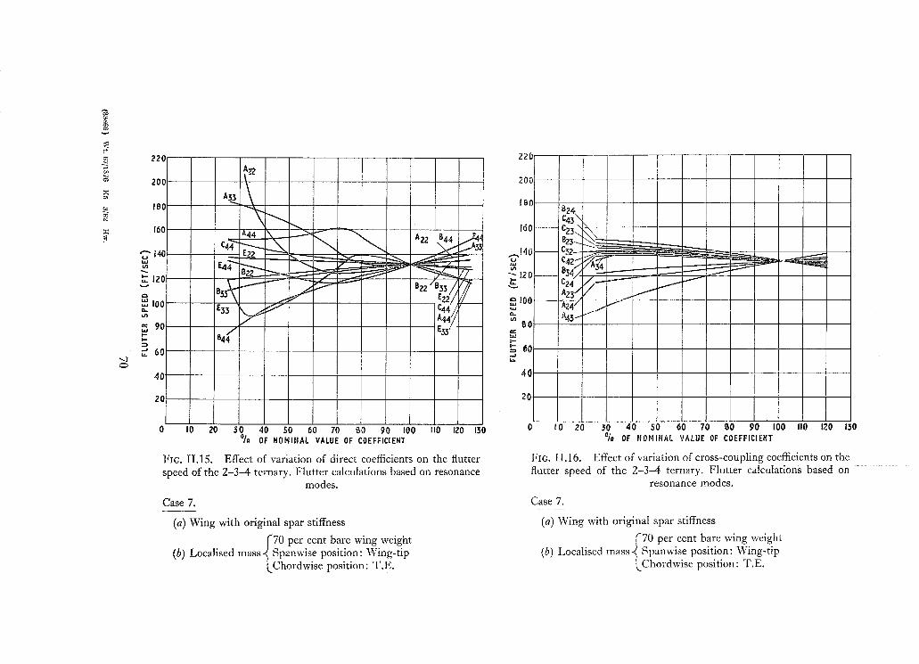
line.Case 7. Localised mass (70 per cent of bare wing weight) at wing-tip on T.E.
(b) Investigations on model with modified spar, simulating a large cut-out.
Case 1A. Bare wing with no localised mass.----
Case SA. Localised mass (70 per cent of bare wing weight) at wing-tip on L.E.
Case 6A. Localised mass (70 per cent of bare wing weight) at wing-tip on 40 per centchord line.
ill all cases, the flutter characteristics were calculated using both arbitrary modes and modesobtained from resonance tests on the model. Equivalent constant strip derivatives were used throughJut, these being estimated from steady motion data in accordance with the procedure given in Ref. 2.
4
-5.1. Arbitrary Mode Flutter Calculations. Three bending modes and three torsion modes wereused in these flutter calculations. All of these modes were simple polynomial functions of the spanwise
'YJ' being the spanwise co-ordinate (y/s).These forms were chosen in the hope that the resulting flutter equations would be sufficiently
well-conditioned for solution on an analogue computer, while the fact that, with the localised masslocated at the wing-tip, any changes in the parameters relating to the mass affected only the 1-4binary, reduced the amount of computation involved. The first of these objects was not achieved,however, and before satisfactory solutions could be obtained from the analogue computer it wasfound necessary to transforr;n the co-ordinates to improve the conditioning. (Ref. 3.)
5.2. Flutter Calculations based on Resonance Test Modes. Resonance modes from the testsdescribed in Section 4.2 were used in these investigations. The tests had covered the frequencyrange 0 to 20 c.p.s, and the number of resonances found within this range varied from four inCase 1, to six in some of the other cases.
In general, the modes were not strictly orthogonal, and the flutter equations were solved with andwithout inertia couplings included in them. The possibility of orthogonalising the modes to get ridof these inertia couplings was considered but rejected, since the existence of a cross-inertia impliesthe existence of a cross-stiffness as well and there seems to be no reliable means of evaluatingthe latter.
(Further details of both these and the arbitrary mode flutter calculations, including the matricesof coefficients, are given in Appendix II.)
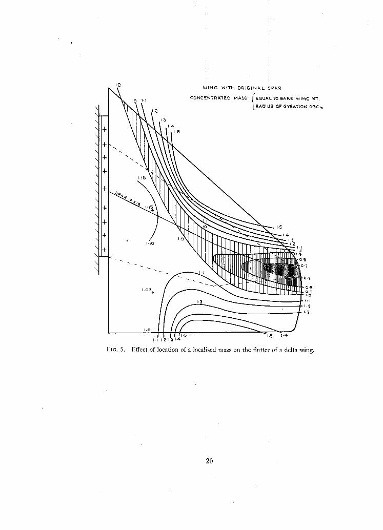
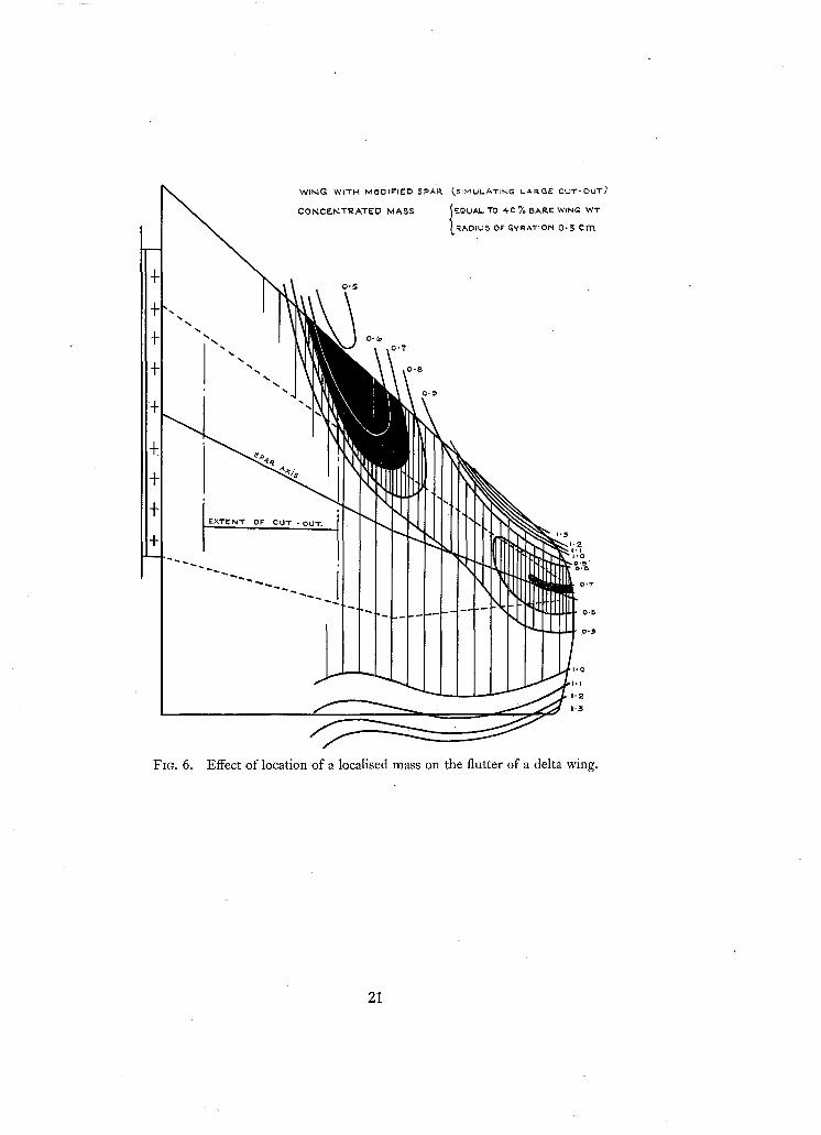
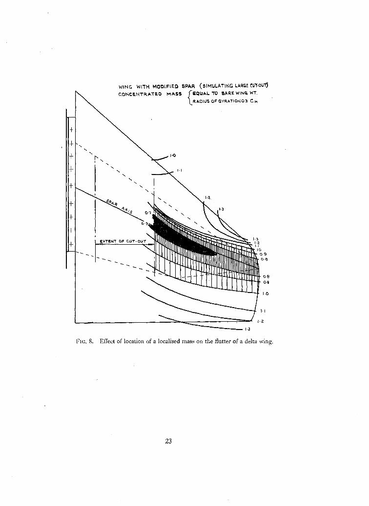
6. Results. 6.1. Results of Wind Tunnel Flutter Tests. The results of wind tunnel tests todetermine the effects of the spanwise and chordwise position of a localised mass are presented in theform of flutter 'contours' drawn on the plan form of the wing. These contours, which are lines ofconstant flutter speed and spaced at intervals of 10 per cent of the bare wing flutter speed, are basedon the detailed wind tunnel test results given in Appendix I. The shaded areas are those in which thepositioning of a localised mass will reduce the flutter speed below that of the bare wing. Figs. 3, 4and 5, show the contours for the original delta wing with localised masses equal to 40, 70 and·100 per cent of the bare wing weight. For the wing with the spar modified to simulate a large cut-out,the relevant contour plots are given in Figs. 6, 7 and 8 respectively.
6.1.1. Investigation of the effects of spanwise and chordwise location of a localised mass on the original
delta wing. Flutter 'contours' for a localised mass equal to 40 per cent of the bare wing weight areshown in Fig. 3. It will be seen that, with the exception of a small region of the leading edge towardsthe tip, the placing of such a mass anywhere forward of the mid-chord position wiIllower the flutterspeed below that of the bare wing. There are two areas in which the placing of the mass will produce
5
particularly low flutter speeds, one centred on the leading edge at mid-span and one on the spar
axis at the wing-tip. Flutter speeds appreciably in excess of that of the bare wing are associated with
the mass very close to the leading edge from about 70 per cent semi-span outboard to the wing-tip,
and with it well aft, towards the trailing edge. These regions in which the presence of the localised
mass improves the flutter characteristics are by no means synonymous with those in which theplacing of the mass produces overtone type flutter, the latter being limited to a small part of the
leading edge in the immediate vicinity of the wing-tip.When the localised mass is increased to 70 per cent of the bare wing weight the contours assume the
form shown in Fig. 4. There is little change in the wing-tip region, but further inboard there aresignificant alterations. At mid-span, the area in which the localised mass will produce a low flutterspeed has moved back from the leading edge towards the spar axis and there is now a narrowregion along the entire leading edge in which the localised mass improves the flutter characteristics.This improvement is most marked for positions towards mid-span, the flutter speeds being morethan 50 per cent above that of the bare wing and above the maximum obtainable in the wind tunnel.For this reason the only direct evidence that the flutter is of the overtone type has been obtained
with the localised mass at the wing-tip, but, from the form of the chordwise plots of flutter speedand frequency in Appendix I there seems little doubt but that the flutter will be of this type with
the mass anywhere in the region.
Aft of the spar axis, the changes in the form of the contours associated with the increase in the
localised mass from 40 to 70 per cent of the bare wing weight are not very significant. Locations
well down towards the trailing edge raise the flutter speed appreciably above that of the bare wing
and in this respect the mid-span position seems particularly favourable. Generally speaking, the
flutter motion is of the fundamental type, but with the mass at the wing-tip trailing edge the
transition to the overtone type has occurred. It is suspected that a similar transition may occur with
the mass on the trailing edge at mid-span, but the corresponding flutter speed was above the maximum
that could be obtained in the wind tunnel.
With a localised mass equal to the bare wing weight, the flutter contours are as shown in Fig. 5.
Comparison with those corresponding to the smaller masses shows that while the pattern remains
much the same for a localised mass in the region of the wing-tip, the situation further inboard ismuch improved. Along almost the entire leading edge the addition of a localised mass of this
magnitude will give a flutter speed well above that of the bare wing. The highest flutter speedappears to be associated with the mid-span position and at this section the mass may be located asmuch as 35 per cent of the chord aft of the leading edge without the speed falling below that of thebare wing. Overtone flutter occurs with the mass located in part of this leading edge sector, butthe transition is not coincidental with the unit contour and flutter speeds in excess of that of thebare wing have been found with motion that is still of the fundamental type.
Behind the spar axis, the situation is much the same as with the smaller masses, at least so faras the flutter speed is concerned. As regards the type of flutter motion, however, there has been a
reversion to the fundamental form for a localised mass at the wing-tip trailing edge. The overtone
type may persist further inboard, but the associated flutter speeds were too high for satisfactory
investigation in the wind tunnel.
6.1.2. Investigation of the effects of sponsrise and chordwise location of a localised mass on the modifieddelta wing. (Structural stiffness modified to simulate a large cut-out.) Although this part of theprogramme was carried out at a later stage than the investigations described in Sections 6.1.3
6
and 6.1.4, the work was of the same type as that which gave the results described in Section 6.1.1
(above), and it seems convenient to deal with it at this point.The results obtained with a localised mass equal to 40 per cent of the bare wing weight are shown as
flutter contours in Fig. 6. Comparing this plot with that given for the same mass on the original
wing (Fig. 4), it is seen that there is a broad similarity between them. The unfavourable regionaround the mid-span leading edge is slightly larger, however, and the reduction in flutter speedassociated with it is much more drastic. In contrast, the area near the wing-tip where the localisedmass lowers the flutter speed appreciably below that of the bare wing is reduced in size. Thewing-tip leading edge position is still a favourable one for the positioning of a localised mass butthe other good region, aft of the spar axis, has been reduced to a narrow strip along the trailing edge.The flutter motion is of the fundamental type, except in the case of the mass in the wing-tip leadingedge region.
Fig. 7 shows the contours for a localised mass equal to 70 per cent of the bare wing weight. The lowflutter speed region centred on the mid-span leading edge has extended further aft and furtheroutboard and in its 'depths' the attachment of a localised mass can reduce the flutter speed to lessthan half that of the bare wing. The unfavourable region at the wing-tip seems to have almostdisappeared, however, and there is now an appreciable area towards the trailing edge in which thelocalised mass raises the flutter speed above that of the bare wing. The wing-tip leading edge positionis again favourable and is associated with overtone flutter. Elsewhere, the fundamental type motion is
general, regardless of the flutter speed.When the localised mass is increased to equal the weight of the bare wing the flutter contours change
to the form shown in Fig. 8. The lowest flutter speeds are now associated with a mass close to thespar axis, while locations towards either the leading edge or trailing edge, give speeds in excess of
that of the bare wing. The flutter motion is of the fundamental type for all positions of the localisedmass, however, except for a small area adjacent to the wing-tip leading edge.
An unexpected feature of these results is the apparent falling-off of the flutter speed for a massclose to the leading edge at mid-span (after the initial rise from the flutter 'valley' on the spar axis).
The drop is quite small, however, and may not have any particular significance.
6.1.3. Investigation of the effects of variations in the radius of gyration of a localised mass (see
Figs. 9 and 10). As described in Section 4.1.1, paragraph (b), these investigations were carriedout on the original wing with a localised mass equal to the bare wing weight. The radius of gyration
was varied from 20 per cent to 40 per cent of the wing mean chord with the mass located atfour different stations, viz: .
(i) Wing-tip leading edge.
(ii) Wing-tip trailing edge.
(iii) Mid-span leading edge.
(iv) Mid-span trailing edge.With the mass at both of the wing-tip stations it was found that the changes in the flutter
characteristics associated with the specified variation of the radius of gyration were quite negligible.In the case of the stations at mid-span, the results are of limited value, but as far as they go, they
largely support those obtained with the mass at the wing-tip. When the programme of wind tunneltests was drawn up, the choice of the mid-span section seemed reasonable enough. Unfortunately,however, the flutter speeds associated with a mass of this magnitude at both the leading and
7
trailing edges proved to be very high. In the case of the mass at the leading edge, the flutter speed
was above the maximum obtainable in the tunnel, regardless of the radius of gyration.
With the mass at the trailing edge, flutter did occur with radii of gyration equal to 0·20, 0·2+ and
0·32 times cm' but not in the other three cases. The flutter speeds were so close to maximum tunnelspeed, however, that it seems unlikely that this represents any significant trend.
6.1.4. Investigation of the effects of variations in the magnitude o] a localised mass (see Figs. 11 and12). Although the effects of variations in the magnitude of the localised mass were studied in a
broad manner in the part of the programme that produced the data for the flutter 'contours', the
effects of such variations were also investigated in detail for certain stations on the wing. The
stations selected were the same as those chosen for the radius of gyration investigations (see
Section 6.1.3 above), and the tests were carried out on the original wing before the spar was modified
to simulate a large cut-out. The smallest localised mass considered was 40 per cent of the bare wing
weight, and the largest, 100 per cent (i.e., the same as in the flutter 'contour' investigations).
For the wing-tip leading edge position, it was found that the size of the localised mass had no
significant effect on the flutter speed or frequency, the overtone type motion being maintained
over the entire range. At the trailing edge, the magnitude of the mass had little effect on the flutter
speed but large and significant changes occurred in the frequency. 'With the smallest localised mass,
low frequency fundamental type flutter occurred, but, when the mass was increased above half the
weight of the bare wing, this was replaced by the higher frequency overtone type. Further increasesin the magnitude of the mass produced no sensible change in the flutter frequency until, with a massequal to the bare wing weight, there was a sudden reversion to the low frequency fundamental type.
With the localised mass at mid-span, it was not possible to determine the actual flutter
characteristics for the full range of mass variations because in some cases the flutter speed was abovethe maximum speed of the tunnel. However, the number of instances in which this occurred wasless than in the case of the investigation into the effects of varying the radius of gyration of the mass(see Section 6.1.3 above).
The general trend from the results is for the flutter speed to increase with increased mass on either
the leading or trailing edges at this mid-span section. In the case of the leading-edge location, the
flutter speed was well below that of the bare wing for the smaller localised masses, but, beyond a
mass ratio of about one-half, the speed increased very rapidly and soon exceeded the maximum
obtainable in the wind tunnel. It seems probable that this increase in speed was accompanied by a
transition from fundamental to overtone type flutter.
With the mass on the trailing edge the increase in the flutter speed with increasing weight was
far more gradual. It seems possible that a transition to overtone flutter also occurred here when the
localised mass became fairly large but there appears to be some scatter in the recorded frequencies
which would mask such an effect.
6.2. Results of Theoretical Investigations. Theoretical flutter investigations were carried out forten selected cases as described in Section 5. Seven of these cases were for the wing with its original
spar and three for the wing with the spar modified to simulate a large cut-out. In all cases theoreticalresults have been obtained using both arbitrary modes and modes obtained from resonance tests.
6.2.1. Results of arbitrary mode flutter calculations. The results of these flutter calculations are
set out in Table 1, together with the corresponding flutter speeds and frequencies as given by windtunnel tests. The results in each case include the speeds and frequencies given by both the complete
8
SIX degree-of-freedom problem and the dominant binary or ternary. (The degrees-of-freedom,com prising three bending and three torsion modes, are defined in Section 5.1.)
The measure of agreement between theoretical and experimental flutter speeds varies considerably,but in all cases the speed from the six degrees-of-freedom problem is lower than that obtained fromtunnel tests. One peculiar feature of these calculations is the fact that the dominant binary orternary usually gives a flutter speed closer to the experimental results than does the complete senary.
In the case of the flutter frequencies, the values from calculations and tunnel tests for the wing
with its original spar are generally in very good agreement, although there is a notable exception
in Case 7, where the calculations failed to predict overtone flutter. For the wing with the modifiedspar, however, there are only two cases in which comparison is possible and in these the agreement
is rather indifferent.
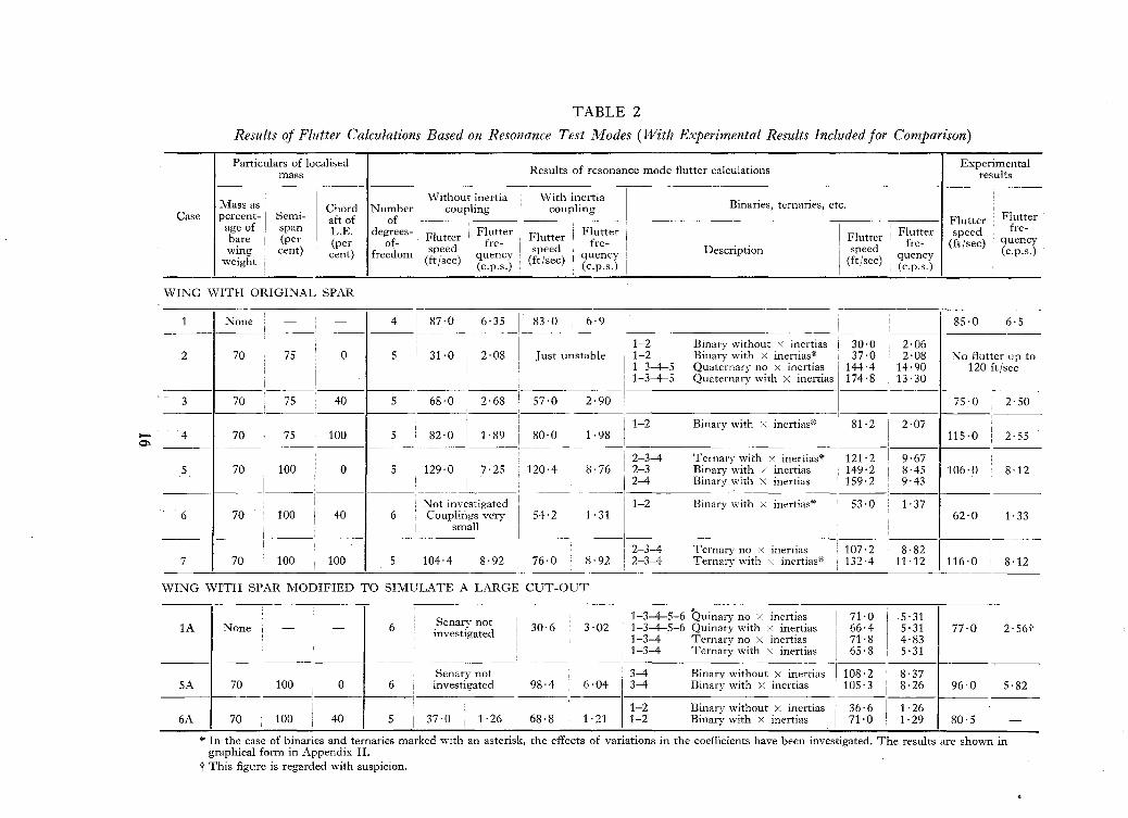
. 6.2.2. Results of flutter calculations based on resonance test modes. The results of these fluttercalculations, together with the corresponding experimental results, are set out in Table 2. In each
case, results are given for the complete problem, involving four, five or six degrees-of-freedom,with the inertia couplings included in the flutter equations. The results obtained without the inertiacouplings and the results for the principal constituents of the problems (e.g., binaries etc.) are alsogiven in most cases.
Generally speaking, the agreement with tunnel tests is quite fair for both flutter speeds andfrequencies. However, in a few instances (notably case 2) there are appreciable discrepancies whichwill be considered later in Section 7 of this Report.
In most cases where the inertia couplings between the dominant degrees-of-freedom are such that(aRS/y'aRRaSS) does not exceed 0·25, the results obtained without the inertia couplings are closerto the test results than the solutions obtained with the couplings included. The foregoing holdsgood for Case 7 which has inertia couplings larger than 0·25, but fails for Case 6A which also haslarge inertia couplings. However, for what it is worth it may be observed that in each of these casesthe higher of the two flutter speeds is closer to the wind tunnel test result.
7. Discussion of Results. 7.1. Wind Tunnel Test Results. 7.1.1. Investigations on the wing withthe original spar. Comparison of the flutter contours of Figs. 3, 4 and 5 shows that the fluttercharacteristics of a delta wing carrying a localised mass are strongly influenced by both its positionand magnitude. At the wing-tip, the position of the mass seems to be the dominant parameter, at
least so far as flutter speed is concerned, and there is little difference between the contours for alocalised mass equal to 40 per cent of the bare wing weight and those corresponding to a mass equalto the bare wing.
For sections further inboard, however, the magnitude of the localised mass becomes increasingly
important, especially if the location is forward of the spar axis. Thus in the leading-edge mid-spanposition, a localised mass equal to 40 per cent of the wing weight reduces the flutter speed some
20 to 30 per cent below that of the bare wing, whereas for masses of 70 per cent of the wing weightand above, the flutter speed is more than one and a half times that of the bare wing. With thelocalised mass behind the spar axis, however, the effects of variations in its magnitude are muchsmaller and there is a general similarity between the contours for all three cases.
Flutter speeds well above that of the bare wing are not necessarily associated with overtone typeflutter motion. It is true that most of the favourable areas towards the leading edge involve thiskind of flutter but aft of the spar axis it is the exception rather than. the rule.
(9
7.1.2. Investigations on the wing with the spar modified to simulate a large cut-out. Despitedifferences in detail, which will be considered later, the results for the wing with the modifiedspar show a broad similarity to those discussed above in Section 7.1.1. The wing-tip leading-edgeposition is favourable in all cases, regardless of the mass involved, but further inboard everythingdepends on the magnitude of the mass. At about mid-span, a mass equal to the wing weight givesflutter characteristics that compare favourably with those of the bare wing, whereas a mass of70 per cent of the wing weight brings the flutter speed right down to less than half that of the barewing. With the localised mass well aft, the flutter contours for the three localised mass weights showrather more variation than in the case of those for the original spar, but the overall picture remainsthe same.
Although a localised mass near the trailing edge can raise the flutter speed well above that of thebare wing, the flutter motion remains fundamental in type. Overtone flutter is limited to casesinvolving high flutter speeds with the mass close to the leading edge.
Differences between the results obtained for the wing with its original spar and those for the wingwith the modified spar, are mainly associated with the extent of the adverse flutter regions and the
minimum flutter speeds that occur when a localised mass is placed within them. Generally speaking,
the overall effect of these differences is that a localised mass at the tip of the wing with the modified
spar is less likely to produce trouble than a mass in a similar position on the original wing, but further
inboard the positions are reversed.
7.1.3. Effect of variation of the radius of gyration of the localised mass. Although a special series
of tests were carried out to study in detail the effects of variations in both the magnitude and radiusof gyration of the localised mass, the powerful influence of the actual weight on the flutter
characteristics, together with the fact that a broad variation of mass had been covered in the mainseries of investigations, made it convenient to include the effects of mass variation in Section 7.1.1and 7.1.2 above.
In contrast to the powerful effect of variations of the mass itself, it seems that variations in theradius of gyration have no appreciable effect on the flutter characteristics. This result is consistentwith that given for wings of higher aspect ratio in Ref. 1.
7.2. Appraisal of Theoretical Results. In this section it is proposed to consider the results of thetheoretical investigations in detail and to discuss possible reasons for the discrepancies that existbetween them and the experimental results in certain cases.
Cases 1 to 7 inclusive relate to calculations on the wing with its original spar and cases lA, SAand 6A to the wing with the spar modified to simulate a large cut-out. In all cases except 1 and lA,which relate to the bare wing with no localised mass, the mass was equal to 70 per cent of thebare wing weight.
7.2.1. Discussion of Individual Cases. Case 1: Bare wing. Arbitrary mode calculations gaveresults that are in reasonable agreement with those from wind tunnel tests.
In the case of calculations based on resonance test modes the agreement is very good and it
appears that the moderate inertia couplings that existed between modes had no significant effect.
Case 2: Mass at 75 per cent semi-span, L.E. No direct comparison is possible in this case as the
only information available from the tunnel tests is that the flutter speed is above 120 ft/sec. This isconsistent with the results of arbitrary mode flutter calculations, however, which indicate overtone
flutter at approximately 130 ft/sec.
10
In contrast, the work based on resonance test modes gives a very low speed fundamental typeflutter. The trouble is due to the fundamental bending-fundamental torsion binary and if thelatter mode is removed from the flutter equations the resulting quaternary gives flutter characteristicsthat agree quite well with those given by the arbitrary mode calculations.
The effects of varying the coefficients in the binary have been investigated in the hope that someclues to the problem might be forthcoming but no justification can be found for the modificationsthat would be necessary to push the flutter speed up.
Case 3: Mass at 75 per cent semi-span, 40 per cent chord aft of L.E. There is a tolerable measureof agreement between the results of both sets of flutter calculations and the tunnel test results in
this case.The flutter is of the fundamental type and both sets of calculations are dominated by the first
bending-first torsion mode binary.Case 4: Mass at 75 per cent semi-span, T.E. Although the results from arbitrary and resonance
mode calculations agree quite well in this case, both appreciably under-estimate the flutter speed asgiven by wind tunnel tests.
The flutter motion is of the fundamental type and the effects of coefficient variation in thedominant fundamental binaries have been investigated for both sets of calculations.
Case 5: Mass at wing tip, L.E. The agreement between the results of arbitrary mode fluttercalculations and those from wind tunnel tests is fairly satisfactory in this case. The calculations weresuccessful in predicting the overtone type of flutter, the solution being dominated by the secondbending-second torsion mode binary. This binary gave a flutter speed closer to the experimentalresult than the complete senary but the frequency was not so good.
The calculations based on resonance modes also gave reasonably good results in this case, althoughthe fact that the theoretical flutter speed is higher than the experimental result is an undesirablefeature. Investigations into the effect of coefficient variations in the dominant ternary have shownthe most effective modification to bring down the flutter speed would be a reduction in the structuralstiffness coefficients but no valid reason can be found to justify such changes.
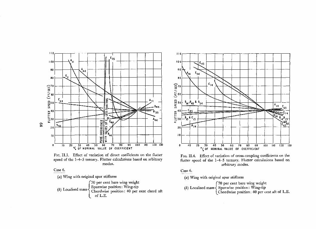
Case 6: Mass at wing tip, 40 per cent chord aft of L.E. The agreement between the results ofarbitrary mode flutter calculations and tunnel test results is indifferent in this case. Although theflutter frequencies agreed very well, the flutter speed was badly under-estimated inthe calculations.An investigation of the constituent binaries and ternaries showed that neither the 1-4 (fundamental)or 2-5 (first overtone) binaries gave anything like the complete senary solution and the nearestapproximation to it was given by the 1-4-5 ternary. This ternary gave a flutter speed appreciablycloser to the tunnel test result than the complete set of flutter equations and the variations in thecoefficients to give still better agreement were investigated. It may be significant that the flutterspeeds for both the 1-4 and 2-5 binaries were close together in this case but it is not clear why thisshould affect the solution given by the full set of modes.
In the case of the resonance mode flutter calculations, however, the agreement with experimentalresults is quite satisfactory. The inertia couplings between the modes are very small and make nosignificant difference to the result of the dominant fundamental bending-fundamental torsionbinary.
Case 7: Mass at wing tip T.E. The arbitrary mode flutter calculations in this case gave ratherunsatisfactory results. The flutter speed was appreciably under-estimated and fundamental typeflutter was obtained instead of the overtone type found in wind tunnel tests. It appears from the
11
investigations that were carried out on the constituent binaries that the solution was dominated bythe fundamental 1-4 binary, whereas the 2-5 overtone binary would give flutter characteristics inreasonable agreement with the tunnel test results. Modifications corresponding to a rearward shift
of the mass e.g. were tried in an attempt to suppress the 1-4 binary but without success.
In the case of the resonance mode flutter calculations there is an appreciable difference betweenthe results obtained with and without the inertia couplings included in the flutter calculations.
This was to be expected, however, as the set of modes in this case was poor, with large inertia
couplings. The flutter frequencies were in fair agreement with the tunnel test results, as was the
flutter speed for the solution without cross-inertias, but the speed with the couplings included was low.
Case 1A: Bare wing; modified spar with cut-out. Arbitrary mode flutter calculations gave a
flutter speed that is in fair agreement with that obtained in wind tunnel tests but the frequency
appeared to be badly over-estimated. The experimental frequency recorded in this case seemsextremely low, however, and is regarded with some suspicion.
In the case of the calculations based on resonance test modes, the complete set of equations gavea very low flutter speed. The solution was dominated by a binary comprising the fundamentalbending mode and a mode that looks like fundamental torsion. However, the frequency of thistorsion mode seems unreasonably low compared with that obtained for the model with the originalspar and it is badly coupled with some of the other modes. If this mode is rejected as spurious, thesolution of the resulting quinary gives a flutter speed that agrees quite well with the tunnel test andarbitrary mode results, while the flutter frequency is close to that given by the arbitrary modecalculations.
Case 5A: Mass at wing tip, 40 per cent chord aft of L.E.; modified spar with cut-out. In this case,the arbitrary mode calculations gave a flutter speed that agrees reasonably well with the tunneltest result, although the calculated flutter frequency is rather high.
The results of the resonance mode flutter calculations are particularly good in this case. Thedominant overtone binary gave a fair approximation to the flutter speed but the frequency wasmuch improved by the inclusion of the other modes.
Case 6A: Mass at wing tip, 40 per cent chord aft of L.E.; modified spar u,ith cut-out. The agreement
between the results of arbitrary mode flutter calculations and wind tunnel tests is poor in this case.Investigation of the constituent binaries and the dominant ternary revealed a situation similar tothat existing in Case 6.
In the case of the calculations based on resonance test modes the position is also unsatisfactory
although the trouble here is only too plainly due to poor modes with large inertia couplings. Thesolution with the inertia couplings included in the flutter equations agrees quite well with the
tunnel test results but the speed obtained with the couplings excluded was very low and close to thearbitrary mode result.
7.2.2. General discussion of theoretical results. Although there are a few unfortunate exceptions,the results of the arbitrary mode flutter calculations are generally in fair agreement with the windtunnel test results. In all cases the flutter speeds have been under-estimated, which suggests eitherthat the structural stiffness coefficients are inclined to be rather low or that there is appreciabledamping in the actual model.* However, the fact that there is no general trend for the flutter speeds
* It has been suggested that the aerodynamic derivatives, based on Minhinnick Rules, may also contributeto conservative estimates of flutter speeds.
12
obtained from calculations based on resonance modes to be low seems to disprove the dampinghypothesis. It seems probable, therefore, that the trouble is due to the stiffness coefficients, thesebeing notoriously difficult to calculate to a high degree of accuracy, especially in the case of sweptana delta wings (Ref. 4).
The calculations based on resonance test modes generally yield better results than the arbitrarymode calculations, subject, of course, to the proviso that the initial set of modes should be fairlygood and free from large inertia couplings. It seems questionable, however, whether the superiorityof the results obtained using these modes is really sufficient to justify the time and labour necessaryto carry out the tests and analyse the results, especially since there is always the possibility that theset may prove to be poor, with the modes not really orthogonal.
In contrast, the ease with which variations in the basic parameters can be introduced into calculationsbased on simple arbitrary modes makes this approach very attractive in a research programme orin the early stages of the design of a new aircraft. Whether or not the use of such modes is desirablebeyond the project stage involves other factors outside the range of this Report however, and thequestion has, in any case, been dealt with very fully in Ref. 4.
8. Conclusions. The investigations carried out in this research programme have shown that theeffect of a localised mass on the flutter characteristics of a delta wing are dependent mainly on (a) themagnitude of the mass, (b) its spanwise and chordwise positions and (c) the stiffness distributionsof the wing itself. Variation of the radius of gyration of the mass seems to have no significant effecton the flutter characteristics.
In a favourable position, a localised mass can raise the flutter speed to more than 1· 5 times that ofthe bare wing, while in an unfavourable position, the mass may reduce it to less than 0·5 timesthe bare wing speed. The position and extent of these favourable and unfavourable regions isdependent, however, on the mass value and the stiffness distribution of the wing. A localised massplaced close to the leading edge between, say, O:7 semi-span and the wing-tip generally improvesthe flutter characteristics, but, further inboard, it seems that the leading edge region should beregarded with caution. If the mass is very large (of the order of the bare wing weight), the flutterspeed is likely to be higher than that of the bare wing, but for smaller masses in this position thespeed may be very low. This effect was accentuated by the modification of the wing spar to simulatea large cut-out.
As in the case of wings of higher aspect ratio, the positioning of a localised mass in the vicinity ofthe structural axis always seems to have an adverse effect on the flutter characteristics. For positionswell aft of the structural axis, however, the effects of a localised mass on the flutter characteristicsare far more favourable for the delta wing. Flutter speeds well in excess of the bare wing speed havebeen obtained and there is evidence of a transition to overtone type flutter with the mass right downon the trailing edge.
A fair measure of success has been obtained with the theoretical part of the programme. Theagreement between flutter calculations and wind tunnel test results is reasonably close in manycases, while in most of those where appreciable differences have occurred, it has been possible tofind a reasonable explanation for the discrepancies.
No. Author
REFERENCES
Title, etc.
1 D. R. Gaukroger ..
2 1. T. Minhinnick ..
3 E. G. Broadbent ..
4 E. G. Broadbent ..
Wind tunnel tests on the effect of a localised mass on the flutterof a swept-back wing with fixed root.
A.R.C. R. & M. 3141. December, 1953.
A symposium on the flutter problem in aircraft design. PaperNo.4.
A.R.C. 16,081. May, 1953.
Ill-conditioned flutter equations and their improvement forsimulator use.
A.RC. C.P. 298. June, 1956.
Research on wing and control surface flutter with particularreference to the choice of co-ordinates.
A.RC. 17,872. June, 1955.
BIBLIOGRAPHY
In addition to those reports to which direct reference has been made herein, the following have also beenreferred to in the course of these investigations.
No. Author Title, etc.
1 D. R. Gaukroger, E. W. Chappleand A. Milln.
2 D. R. Gaukroger and D. Nixon ..
3 D. R. Gaukroger ..
4 W. G. Molyneux ..
5 D. R. Gaukroger ..
6 H. Hall and W. A. Coles ..
Wind tunnel flutter tests on a model delta wing under fixed andfree root conditions.
A.RC. R. & M. 2826. September, 1950.
Wind tunnel tests on anti-symmetric flutter of a delta wing withrolling body freedom.
A.RC. C.P. 259. February, 1955.
Wind tunnel tests on the effect of spar variations on the flutterof a model wing.
A.R.C. 18,937. July, 1956.
Flutter of wings with localised masses.A.R.C. 19,062. July, 1956.
A theoretical treatment of the flutter of a wing with a localisedmass.
]. R. Ae. Soc. Vol. 63. No.2. p.95. February, 1959.
Wind tunnel tests on the effects of an added mass on the flutterof a model delta wing.
* In the case of binaries and ternaries marked with an asterisk, the effects of variations in the coefficients have been investigated. The results are shown ingraphical form in Appendix II.
t This figure is regarded with suspicion.
TABLE 2
Results of Flutter Calculations Based on Resonance Test Modes (With Experimental Results Included for Comparison)
Particulars of localisedResults of resonance mode flutter calculations
Experimentalmass results
----- --
Mass asI
Without inertia With inertiaBinaries, ternaries, etc.Chord Number I coupling coupling
WING WITH SPAR MODIFIED TO SIMULATE A LARGE CUT-OUT---- -. ----,
1-3--+-5-6 Quinary no X inertias i 71·0
I
·5 ·31Senarv notlA None - - 6 investigated I
30·6 3·02 1-3--+-5-6 Quinary with X inertias ! 66·4 5·31 77·0 2· 56t1-3-4 Ternarv no X inertias 71·8 4·83
i:
1-3-4 Ternary with X inertias I 65·8 5·31I
!
I Senary not 3-4 Binary without X inertiasi
108·2 I 8·37SA 70 100 0 6 ! investigated 98·4 6·04 3-4 Binary with x inertias I 105·3 i 8·26 96·0 5·82I I i
I 1-2 Binarv without X inertiasI
36·6 II 1·266A 70 100 40 5 I 37·0 1·26 68·8 1· 21 1-2 Binary with X inertias I 71·0 1·29 80·5 -
I I
* In the case of binaries and ternaries marked with an asterisk, the effects of variations in the coefficients have been investigated. The results are shown ingraphical form in Appendix II.
t This figure is regarded with suspicion.
a: (898S8)
it
29·48" "''" IAIIIIIIIIIIIIIIIIIIIIIIIIIIIIIIII':jll I
I ROOT DATUM (0,," SEMI-SPAN) I 7
e I II /
/I
III
e
e / /
//
~16I
/
II
I
~.I~ e ) II I
I Ii
@ II
e 1 III
/
€>i /I /I (
@,
o.
==_1-
soc,
f!.
r-
>'1'j
?i
o8S(1)
~o......c,
~I'l
~S·
C1CI::bi=......(1)...
I...·I~ ~·I~,U'I 0. 'IQ
'" - '"•
....o
'"•
DRILLED HOLE
~"""I"""I .. '1 .....
,, ,.-..
7·40"
/7 SAW CUTS PITCHED I·ZS"TERMINATED BY A '/16"DIA.
o I" "oJ' JU. ~
....'"
1-1 n·n I %0. .. ... J. ~
Y' :~.
'".... 1';'1 I'"~. o~ ~=
>'1'j
?itv
en"0I'l...
C1CI(1)03(1)......
'-;<:
..:~G'>::z:-l..CD...r-~
WING WITH ORIGINAL SPAR
CONCENTR"-TED MASS {4-0% OF BARE WING WT.
RADIUS OFGYRATION 0·3 em.
--- ---- ---
--- --FIG. 3. Effect of location of a localised mass on the flutter of a delta wing.
18
--
WING WITH ORIGINp..L SPAR
CONCENTR.ATED MASS {70% OF' BARe: WING WT.
RADIUS OF"GYRATION 0-3Cm.
0·70
0'800·90,,00
1'10
"20
.' 30
,.1·30
"2.01010
(83868)
FIG. 4. Effect of location of a localised mass on the flutter of a delta wing.
19
B2
+
I·a
'.0
I·j
WING WITH ORiGINAL SPAR
CONCENTRl>.iE.D MA5S {E.QUAL TO e>I>.RE. WING 'Wi.
R"'OIUS OF GYRATION 0·~C1'l\
0·1
O·Il
--.........-L..J...J...J..l-'-+ ~c"
~--------t,.,~--------+ ,.<
-----------r- '·3
FIG. 5. Effect of location of a localised mass on the flutter of a delta wing.
20
WING WITH MOOIFIEO SPAR (SIMULAT't>JG LAR.Ge: CUT· OUT)
+
++++
CONCENTRATED MASS
EXTENT OF CUT· OUT.
~~-
--------- I---- ------ - -
{
EQUAL TO "1-0 '7. BARE WING WT
RADIUS OF GYRATION 0·3 em
0·8
FIG. 6. Effect of location of a localised mass on the flutter of a delta wing.
21
WING WITH MODIFIED SPAR (SIMULATING LARGE CUT-OUr)CONCENTRATED MASS {EQUAL TO 70
G/o BARE WING vr.
RADIUS OF GYRATION 0'3 em
+
+<,
+ -,-,
<,
+<,
<,<,
-,<,
<,
t
+t
+
--.
I· 0
f· ,
/'2
FIG. 7. Effect of location of a localised mass on the flutter of a delta wing.
22
WING WITH MOOIFIED SPAR (SIMULATING L.ARG.E CUT·OU"CONCE.NTR.Aie.O MASS {EClUAI.. TO BAR.E WING WT.
Fl,"DIUS OF GYRATION 0,3 Co",
++ ....
....
+ <,
!" ....
+ ....-, ,.,
+
+++
+
o·ao·g
1·0
I·'
-------1.3FIG. 8. Effect of location of a localised mass on the flutter of a delta wing.
23
LOCALISED MASS ON LEADING EDGE LOCALISED MASS ON LE.A-Cl\NG EOGE
BARE WING .LUTTER SPE.E.O ANO FREQUE.NCY SHOWN THUS - - -
auJ*501----\--+-+--+--1----1
'"uJt-t-::JJ"ol-_-'-_..L.._-L._-l._---'_-'
10
a10 20 30 40
RAOIUS 00 GVR~"110N (AS %ME~N CKORO)
-"'-~
- -- - ---1~--
10
1;z!'leulg'
~tt-
3u 0
10 ao 30 40
RAOIUS 01= GYRATION (AS "l...MEAN CHORD)
onU
- -- -
10onU
FIG. 9. Flutter of a delta wing carrying a localised mass.Variation of flutter speed and frequency with radius of gyration ofa localised mass equal to the bare wing weight. Localised mass
at wing-tip.
LOC~LISEO MASS ON TRAILING EDGE.
FOR THE CASE WI"1H LOCALISEO
MASS ON THE LEIl.OING EDGE
FLUTTER WIl.S NOT OBTIl.INEO
WITHIN THE SPEEO RANGE
01' THE WIND TUNNEL
u~ 100
t-U.
auJuJ
~ 50
'"Wl-I-::>Ju,
/ /ir-,@" ''<i)'
- -----
-
I--- - --
o
a10 2,0 30 40
RAlJIUS OF GYRATION (AS °/0 ME~N CHORD)
BARE WING FLU"11ER SPE.EO AND FREQUENC~
SHOWN THUS'" 10U
1:;zs::: 5u,
<turl::::3" 0
\0 ao 30 40
R~OIUS OF GVR~"110N (AS '10 ME"N CHORO)
FIG. 10. Flutter of a delta wing carrying a localised mass.Variation of flutter speed and frequency with radius of gyration ofa localised mass equal to the bare wing weight. Localised mass at
50 per cent at semi-span.
24
MASS ON LEAOINC:; aeca . MASS ON ,~AILINC; eoc:;e.
-",r--- f-- --,..-- - ---
oIS so '5 10.
,OCA"SEO MASS (AS% OF WINO W,.)
,r-- --_. - r.---r--'
0is«
~ oas so 75 10.
1.0eAI.ISliC MA~S (AS 0/0 OF WINC 'W")
"~O...
r---Ii --f-- --H-: Ii I
~ ~
gS:s'"...~I-
~ cZ5 50 75 10.
LOCALISEO MASS (AS '/0 OF WINe w,)
..U-
BA~E WIN(4 FL.U""T'I!!R. $PUO AND FAEQUENC.... SHOWN iHL.lS-·-·
10
~- - 1-- --f--.
o25 50 75 100
,OCALISEO MASS (AS % 0' WINC W,)
10
FIG. 11. Flutter of a delta wing carrying a localised mass.Variation of flutter speed and frequency with magnitude oflocalised mass. (Constant radius of gyration equal to 30 per cent
wing mean chord.) Mass at wing-tip.
MASS A, LEA01NC:; EOC;E. MASS AT ,RAILINC:; EOC:;E.
~ 100......
D....::; so~tI-
:3lL
f--.1----- .-f--.
Is-- flf/
" 100
--...u,
SO
~
:-- .-_. l- .-'-.-
oIS so 75 100
LOCALISEO MASS (AS % BA~E WINO W'1
o25 so 75 100
LOCALISEO MASS (AS Of, BARE WINe; W,.)
_. f--_.....,
~. - .-r \
I I I1-0>-- II!J/ \ /
BARE WINO FLUHeFl SPEED ANO FREQUENCY SHOWN ,HUS -.-_.10
f-- - .-_.
la.. "" ~I-
3...o 0n so 75 100 IS 50 75 100LOCALIS'O MASS (AS 'j. BARE WINO WT) LOCALISEO MASS (AS ./. BARE WINC w,.)
FIG. 12. Flutter of a delta wing carrying a localised mass.Variation of flutter speed and frequency with magnitude oflocalised mass. (Constant radius of gyration equal to 30 per cent
wing mean chord.) Mass at 50 per cent semi-span.
elI-
:3..
25
APPENDIX I
Wind Tunnel Flutter Tests
1. Introduction. The experimental part of the research programme has already been briefly
described in Section 4 of the main part of this Report. However, in this Appendix the actual test
procedure will be considered in more detail and the results obtained will be given in full.
2. Range of Investigations. The wind tunnel flutter test programme included an extensive range
of investigations on the effect of a localised mass on the flutter of the original wing and a more
restricted series of tests on the model after the spar was modified to simulate the effect of a large
cut-out, such as an undercarriage bay.
In the work on the original wing, a detailed investigation was carried out with the localised massat each of a series of chordwise stations at four sections on the wing. Three different mass values
were covered in these investigations, while a more detailed study of the effects of variations in the
mass value and the radius of gyration was carried out at certain selected stations.
I n the case of the wing with the modified spar, the investigations were limited to study of the
effect of the chordwise position of the localised mass at the mid-span and wing-tip sections. Three
mass values were covered in this work.
Full details of the tests that were carried out are given in the Tables at the end of this Appendix.
3. Description of the Model. The model wing was of segmented construction, comprising an
aluminium alloy plate spar carrying nine wooden box segments and a tip fairing to give the required
aerodynamic form (see Fig. 1).
The spar was adapted from the taper-machined plate spar used in the SR,53 wing flutter model.
The latter had a high 'bare-wing' flutter speed, however, and the stiffness of the spar had to be
drastically reduced so as to permit investigation of those cases in which the localised mass increases
the flutter speed above that of the bare wing. This reduction in stiffness was achieved by reducing
the effective width of the spar with saw-cuts from the front and rear edges of the plate. For the
first series of tests, i.e., for a wing without a cut-out, the depth of these saw-cuts was graduated so as
to give a fairly smooth grading of stiffness from root to tip. To simulate the cut-out for the second
part of the programme, the cuts in the inboard part of the wing were increased in depth so as to
reduce the effective width of the spar to about one half its previous value. (Details of the spar are
given in Fig. 2.)
All tests on the model were to be carried out under 'fixed root' conditions, so the spar root was
clamped between two substantial angle section members which were bolted to a rigid support for
wind tunnel and resonance tests.
The box segments that provided the aerodynamic form of the wing were constructed of balsa
and thin plywood. A small amount of lead ballast was fitted in these segments to give the required
mass distribution. (Particulars of the weights and e.g. positions of these box segments are given in
Note. This Appendix is based on Westland Aircraft Ltd., Saunders-Roe Division Wind Tunnel ReportsNos. A/2/326a and A/2/326b. The first of these Reports covered tests on the model with its original sparstiffness and the second the tests carried out after the spar was modified to simulate the effect of a largecut-out.
26
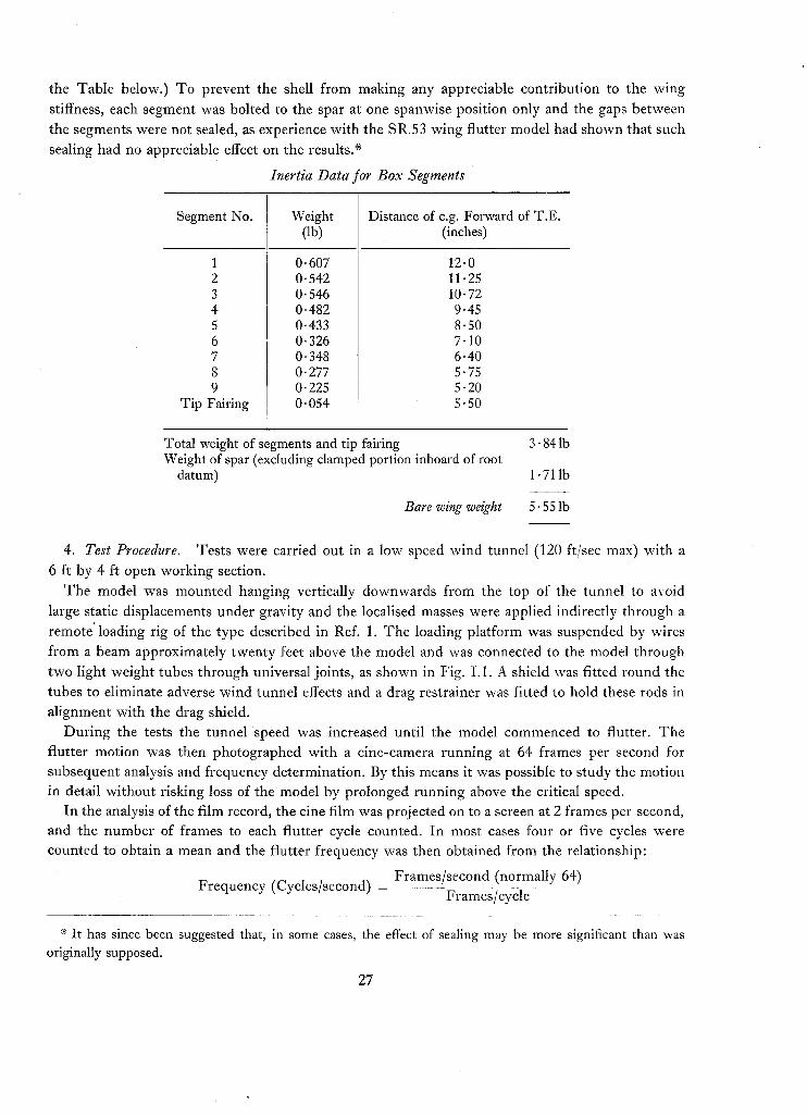
the Table below.) To prevent the shell from making any appreciable contribution to the wing
stiffness, each segment was bolted to the spar at one spanwise position only and the gaps between
the segments were not sealed, as experience with the SR.53 wing flutter model had shown that such
sealing had no appreciable effect on the results.*Inertia Data for Box Segments
Total weight of segments and tip fairingWeight of spar (excluding clamped portion inboard of root
datum)
Bare wing weight
3·841b
1·711b
5·551b
4. Test Procedure. Tests were carried out in a low speed wind tunnel (120 ft/sec max) with a
6 ft by 4 ft open working section.
The model was mounted hanging vertically downwards from the top of the tunnel to avoid
large static displacements under gravity and the localised masses were applied indirectly through a
remote'loading rig of the type described in Ref. 1. The loading platform was suspended by wires
from a beam approximately twenty feet above the model and was connected to the model through
two light weight tubes through universal joints, as shown in Fig. 1.1. A shield was fitted round the
tubes to eliminate adverse wind tunnel effects and a drag restrainer was fitted to hold these rods in
alignment with the drag shield.
During the tests the tunnel speed was increased until the model commenced to flutter. Theflutter motion was then photographed with a cine-camera running at 64 frames per second forsubsequent analysis and frequency determination. By this means it was possible to study the motionin detail without risking loss of the model by prolonged running above the critical speed.
In the analysis of the film record, the cine film was projected on to a screen at 2 frames per second,and the number of frames to each flutter cycle counted. In most cases four or five cycles werecounted to obtain a mean and the flutter frequency was then obtained from the relationship:
F (C I / d)Frames/second (normally 64)
<requency yc es secon = F / 1 ..rames eye e
* It has since been suggested that, in some cases, the effect of sealing may be more significant than wasoriginally supposed.
27
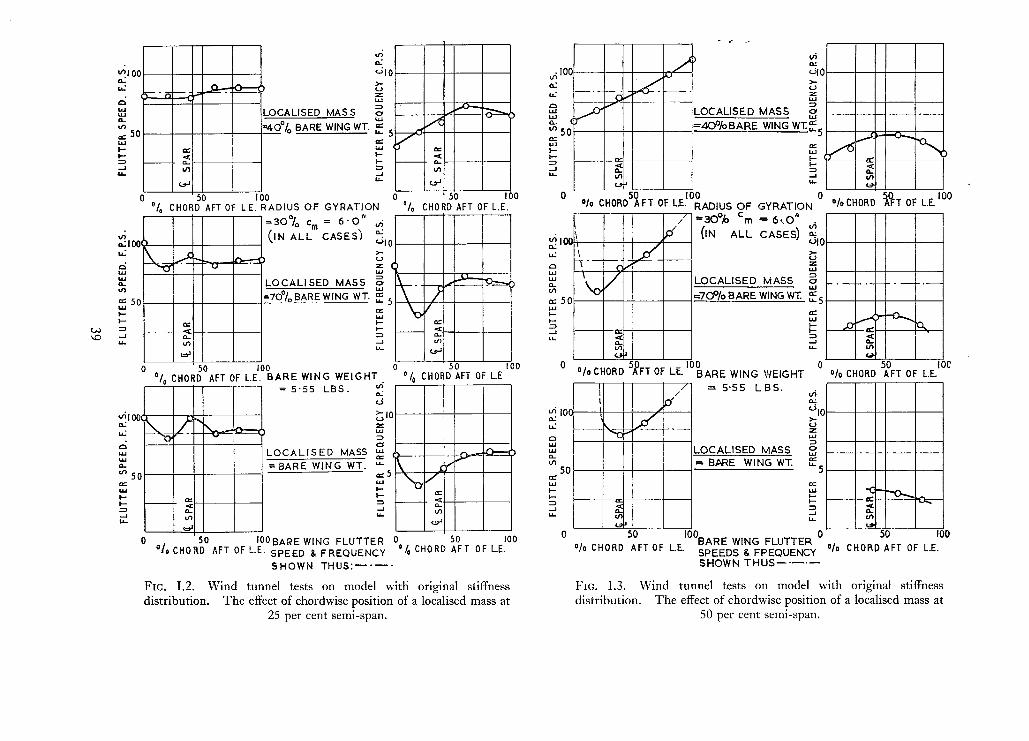
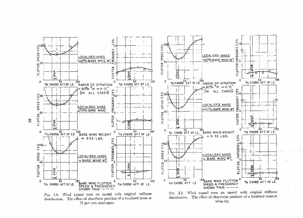
5. Results. The results of these wind tunnel flutter tests have already been presented anddiscussed in the main part of this Report (Sections 6.1; 7.1 and Figs. 3 to 12 inclusive). In the caseof the main series of investigations, however, the results were reduced and given in the form of'flutter contours' (Figs. 3 to 8) without details of frequency or type of flutter motion, although thegeneral characteristics in these respects were noted and discussed in the text.
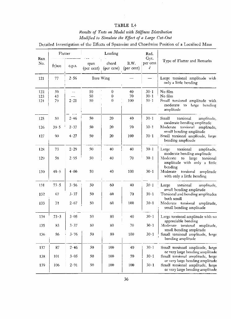
In this Appendix, full details of the results of the main series of investigations on the wing with itsoriginal stiffness distribution and with its stiffness modified to simulate a large cut-out are given
in Tables 1.1 and 1.4 respectively. The variation in flutter speed and frequency with chordwise
location of the localised mass is shown in Figs. 1.2 to 1.7. These diagrams cover the three mass
values at the four spanwise sections on the wing with its original stiffness distribution, and the two
on the modified wing.
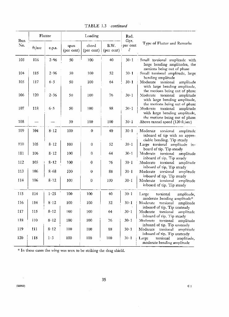
The results for the detailed investigations on the effects of variation in radius of gyration and
magnitude of the localised mass are given in Tables 1.2 and 1.3 respectively. These results werepresented diagramatically in Figs. 9 to 12 in the main part of this Report.
28
TABLE 1.1
Results of Tests on Model with Original Stiffness Distribution
Detailed Investigation of the Effect of Spanwise and Chordwise Position of a Localised Mass
Flutter I Loading Rad.Run - Gyr.
Type of Flutter and RemarksNo. ' span I chord B.W. per cent
ft/sec c.p.s,(per cent) (per cent) (per cent) C
III
0 85 6·5 - Bare Wing - ! Large torsional amplitude,i small bending amplitudeI
1 82 3·82 25 0I
40 I 30·1I
Large torsional amplitude, moder-
i
I
ate bending amplitude. Wingmotion unsteady
2 103 8·12 25 0 70 I 30·1 Very large torsional amplitude
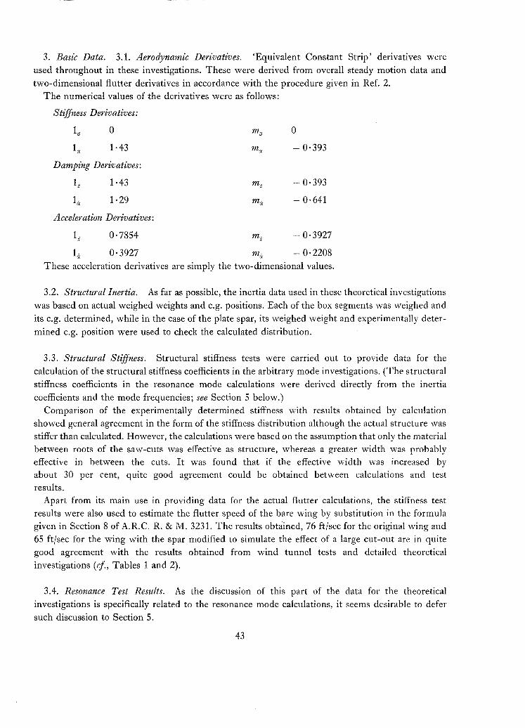
used throughout in these investigations. These were derived from overall steady motion data and
two-dimensional flutter derivatives in accordance with the procedure given in Ref. 2.
The numerical values of the derivatives were as follows:
Stiffness Derivatives:
r, 0
1", 1·43
3.2. Structural Inertia. As far as possible, the inertia data used in these theoretical investigations
was based on actual weighed weights and e.g. positions. Each of the box segments was weighed and
its e.g. determined, while in the case of the plate spar, its weighed weight and experimentally deter
mined e.g. position were used to check the calculated distribution.
3.3. Structural Stiffness. Structural stiffness tests were carried out to provide data for the
calculation of the structural stiffness coefficients in the arbitrary mode investigations. (The structural
stiffness coefficients in the resonance mode calculations were derived directly from the inertia
coefficients and the mode frequencies; see Section 5 below.)
Comparison of the experimentally determined stiffness with results obtained by calculationshowed general agreement in the form of the stiffness distribution although the actual structure was
stiffer than calculated. However, the calculations were based on the assumption that only the materialbetween roots of the saw-cuts was effective as structure, whereas a greater width was probablyeffective in between the cuts. It was found that if the effective width was increased byabout 30 per cent, quite good agreement could be obtained between calculations and testresults.
Apart from its main use in providing data for the actual flutter calculations, the stiffness testresults were also used to estimate the flutter speed of the bare wing by substitution in the formulagiven in Section 8 of A.R.C. R. & M. 3231. The results obtained, 76 ft/sec for the original wing and
65 ft/sec for the wing with the spar modified to simulate the effect of a large cut-out are in quite
good agreement with the results obtained from wind tunnel tests and detailed theoretical
investigations (ef., Tables 1 and 2).
3.4. Resonance Test Results. As the discussion of this part of the data for the theoretical
investigations is specifically related to the resonance mode calculations, it seems desirable to defer
such discussion to Section 5.
43
I, = 1]2
f2 = 1]2 - 1]3
f3 = YJ2 - 3YJ3 + 2YJ4
Mode 2
Mode 3
4. Arbitrary Mode Flutter Calculations. 4.1. Arbitrary Modes. Six arbitrary modes, three
bending and three torsion, were used in these calculations. The modes were simple polynomial
functions of the spanwise co-ordinate 1] (= yjs) and were defined as follows:
Bending Modes
Mode 1
Torsion Modes
Mode 4 f4 = 1]
Mode 5 15 = 1] - 1]2
Mode 6 fn = Tj - 3Tj2 + 2Tj3
Modes 1 and 4 have no nodes, modes 2 and 5 one node and modes 3 and 6 two nodes each.
By having modes that did not resemble each other, it was hoped that the resulting flutter equations
would be sufficiently well conditioned for solution by an analogue computer. In the event, however,
this hope was not realised and it was necessary to change the co-ordinates using the procedure given
in Ref. 3. Further details of this work are given in Section 4.3 below.
4.2. Calculations of Flutter Coefficients. The calculation of the aerodynamic coefficients
corresponding to a set of simple arbitrary modes is a very straightforward procedure and calls for
no comment. As the same modes were used throughout, the same set of aerodynamic coefficients
served for all ten cases. The contribution of the wing structure to the structural inertia coefficients
also remained unchanged and it was only necessary to include the appropriate contribution from the
localised mass in each case.
With regard to structural stiffness coefficients, however, there is no wholly satisfactory procedure
for evaluating them except in the simplest cases, and it seems probable that at least part of the
discrepancies between the results of these flutter calculations and the wind tunnel test results IS
due to trouble with these coefficients.
4.3. Improvement of the Equations for Solution by Analogue Computer. As has already been
mentioned in Section 4.1, the flutter equations obtained from the chosen arbitrary modes were too
ill-conditioned for satisfactory solutions to be obtained from an analogue computer. It was
necessary, therefore, to transform the equations so as to improve the conditioning.
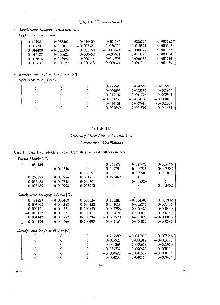
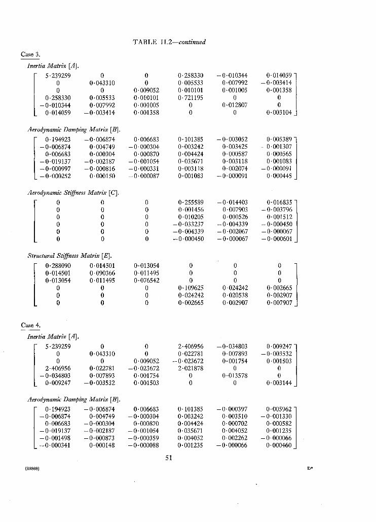
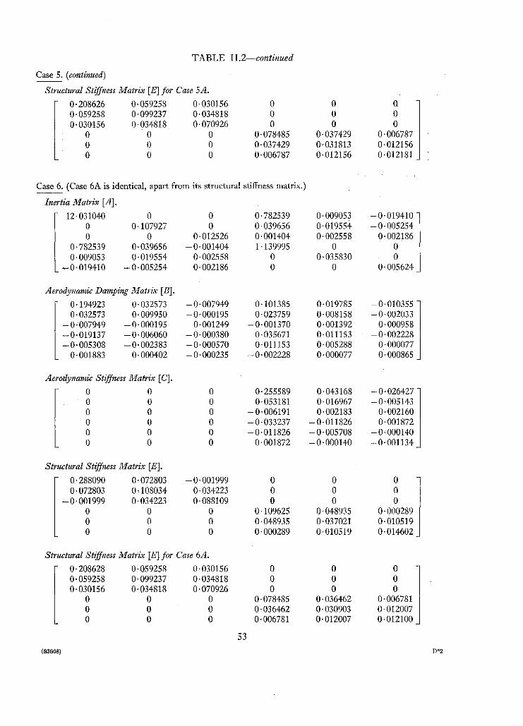
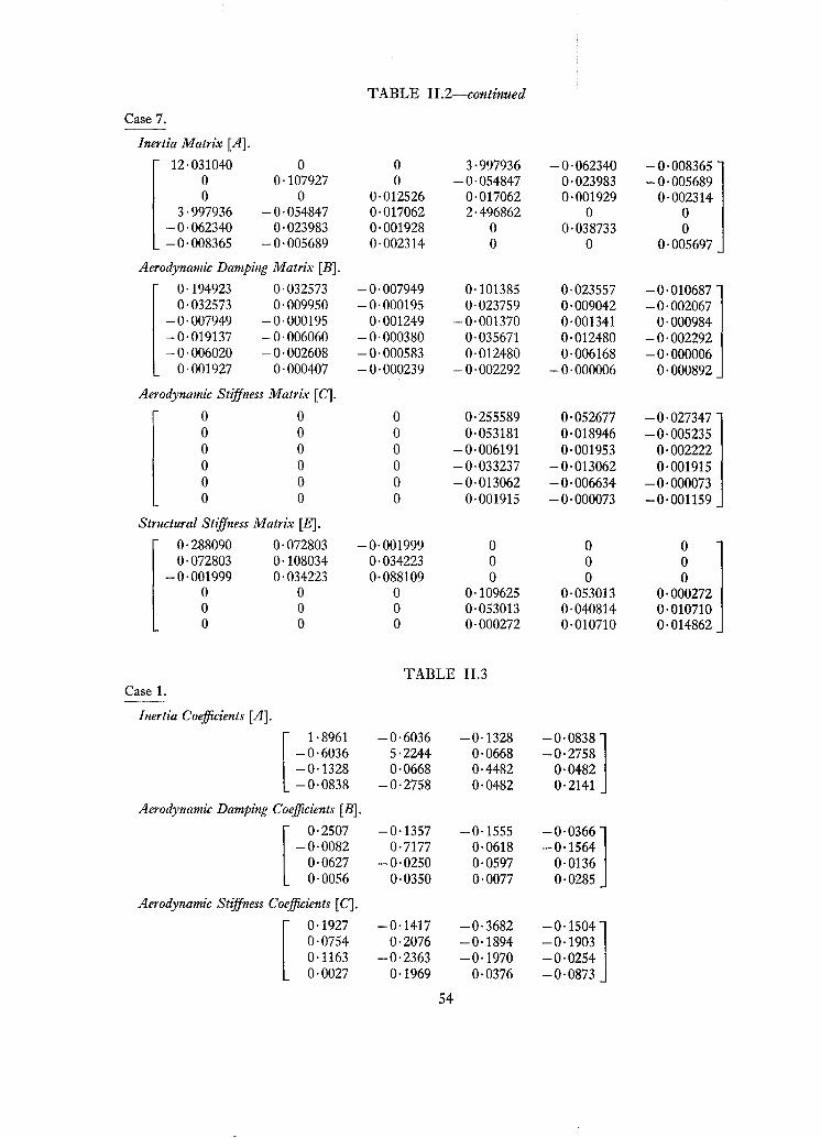
To effect this improvement, the co-ordinates were changed in accordance with the proceduregiven in Ref. 3, the inertia couplings between modes of like kind being reduced to zero. The original
flutter coefficients, as obtained directly from the specified arbitrary modes, and the transformed
coefficients for analogue computer solution are given at the end of this Appendix in Tables II.l and
11.2 respectively.
4.4. Results of Arbitrary Mode Flutter Calculations. The results of these arbitrary mode flutter
calculations have been set out in Table 1, and discussed in Sections 6.2.1 and 7.2 in the main part
of this Report.
Recapitulating, the theoretical flutter speeds are all lower than the corresponding results obtained
in wind tunnel flutter tests. In six of the cases, the experimental flutter speed is of the order
44
of 20 to 30 per cent higher than the theoretical estimate, while in the remaining four cases, theexperimental speed exceeds the theoretical results by 50 per cent in Case 7, 70 per cent in Case 4,and more than 100 per cent in Cases 6 and 6A.
The flutter frequencies for those cases relating to the wing with its original spar stiffness aregenerally quite good, although in Case 7, the calculations failed to give the overtone type of flutterobtained in tunnel tests (and resonance mode flutter calculations). For the wing with the modifiedspar, however, the flutter frequencies obtained by calculation were higher than those recorded inthe wind tunnel tests.
In the four cases in which the agreement between the calculations and tunnel test results wasindifferent, further investigations were carried out to try to account for the discrepancies. Theseinvestigations are discussed below:
Case 4. The theoretical solution, which was dominated by the 1-4 fundamental binary, gave aflutter speed that is well below the experimental result but in fair agreement with the result obtainedfrom calculations based on resonance test modes. The effect of varying the coefficients in the 1-4binary was investigated (see Figs. 11.1 and II.2) but there appears to be no justification for alteringany of the coefficients to the extent necessary to raise the flutter speed up to experimental result.
Cases 6 and 6A. The same general characteristics are apparent in the theoretical solutions forboth these cases. The result in each case was dominated by the 1-4-5 ternary, while the 1-4 and2-5 binaries gave flutter speeds much higher than either the ternary or the complete six degree-offreedom problem. It is suspected that the small difference between the flutter speeds obtained forthe 1-4 and 2-5 binaries may have something to do with the trouble in these two cases.
The effects of varying the coefficients in the ternary were investigated in both cases and theresults are shown graphically in Figs. II.3 and IIA for Case 6 and in Figs. II.5 and II.6 for Case 6A.
Case 7. The explanation of the trouble in this case is basically straightforward, the solution forthe complete six degree-of-freedom problem being dominated by the wrong binary. If the 1-4 binarycould be eliminated, the 2-5 binary would give a result that would agree very well with theexperimental result and the flutter would be of the right type. However, investigations in whicharbitrary chordwise movements of the localised mass e.g. were assumed failed to eliminate the1-4 binary.
5. Flutter Calculations Based on Resonance Test Modes. 5.1. Resonance Test Modes. Thefrequency range covered in these tests was approximately 0 to 20 c.p.s., which sufficed to give fourmodes (fundamental and overtone bending and torsion) for the original wing with no localised mass.With the addition of a localised mass the frequencies were generally reduced and more resonanceswere found within the frequency range. Thus in all of the other nine cases that were investigated,five or six resonance modes were available as degrees-of-freedom in the flutter calculations.
The inclusion of these extra modes in the flutter calculations did not generally give superiorresults, however, and the best result was obtained, in fact, from the quaternary in Case 1. In fairness,however, it should be added that there is reason to suspect that in at least some of the cases one ormore of the additional modes may be spurious.
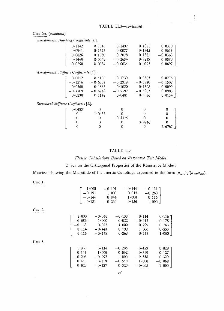
In this connection, the check on the orthogonal properties of the modes, set out in Table IIA, isquite revealing. While in many cases the inertia couplings are generally rather larger than is reallydesirable, certain modes stand out as being particularly bad. Thus in Cases 2, 3 and 4, the fourthmode is notably poor. Further examination of this mode shows that in all three cases the form and the
45
frequency have a considerable resemblance to the fundamental torsion mode of the bare wing. This
looks suspiciously like the effect of backlash in the remote loading rig and seems fair grounds for
rejecting the mode as spurious. Fortunately, however, the fourth mode is fairly passive in all three
cases and is unlikely to influence the results.
Of the remaining cases for the wing with its original spar stiffness, the modes for Cases 5 and 6
are generally quite good while those for Case 7 are poor. Surprisingly enough, the largest inertia
couplings in Case 7 are associated with the first mode.
Turning to the results obtained in the tests on the model with its spar stiffness modified to
sirnu late a large cut-out, most of the modes for Cases lA and SA are fairly good. Both these cases
involve one bad mode, however, as may be seen from inspection of Table II.4. In Case lA, the
second mode is definitely peculiar and gives a low flutter speed if it is included in the flutter equations
(see later). The mode is of fundamental torsion form but the frequency is unreasonably low and it
is probably spurious.
The fifth mode in Case SA is also spurious. In Table II.4 the large coupling between modes
four and five is readily apparent but it is not clear from the couplings with the other modes which
one of them is at fault. In fact, however, the form of the fifth mode was vcry distorted and it was
finally discarded.
I n Case 6A, the results are generally poor with quite large inertia couplings, between nearly all
of the modes. The effects of this are reflected in the results from the flutter calculations.
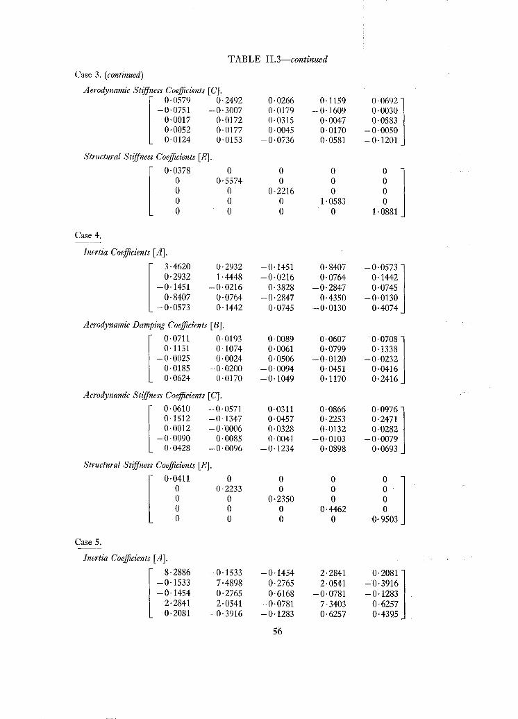
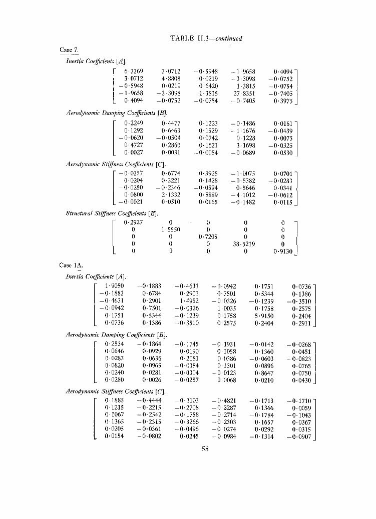
5.2. Calculation of Flutter Coefficients. The coefficients, set out in full in Table II.3, were
computed by the usual matrix multiplication procedure.
5.3. Results of Flutter Calculations based on Resonance Test Modes. The results of these flutter
calculations have already been given in Table 2 in the main part of this Report, and have heen
discussed in Sections 6.2.2 and 7.2.
Of the ten cases investigated, Cases 1, 3, 5A and 6 have given results that are in quite good
agreement with those ohtained from wind tunnel tests, while the agreement is also fair for Cases 4
and 5. These six cases will not he considered further, therefore, and our attention here will be
confined to the remaining four cases in which the agreement is indifferent or poor.
In Case 2 the theoretical investigations gave a very low flutter speed which conflicts with the
evidence from wind tunnel tests. The results from the investigations on the constituents of thecomplete quinary leave little doubt but that mode 2 is the source of the trouble, yet there is no
evidence from either the form of the mode, or from the inertia couplings in Table II.4 that it is
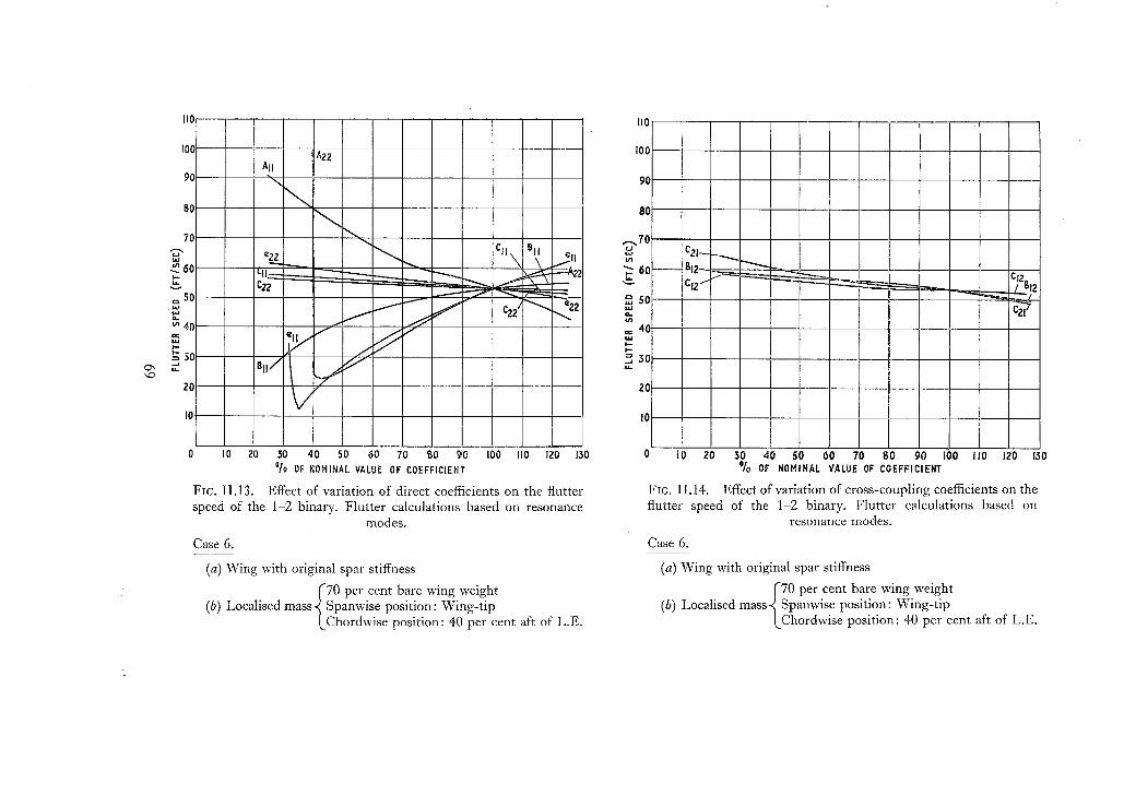
unsatisfactory. The effects of varying the coefficients in the dominant 1-2 binary were investigated
(see Figs. 11.7 and II.R) in an attempt to resolve the problem but no clear-cut explanation was
ohtained. It seems probable, however, that the anomalous result is due to the fact that the flutter
characteristics are acutely sensitive to precise positioning of a localised mass in the region concerned.
A very similar situation arose in the results obtained for Case lA. Here again a very low flutter
speed was given by the complete set of flutter equations. However, there seems to be a straight
forward explanation in this case as there is good reason to believe that the mode which causes the
trouble is spurious. (See Section 5.1 of this Appendix.)
In the remaining two cases, Numbers 6A and 7, the shortcomings in the theoretical results are
quite clearly attributable to lack of orthogonality in the resonance modes. In both cases the solutions
ohtained with and without the inertia couplings included in the flutter equations showed little
46
difference in frequency but a wide variation in flutter speed. The possibility of normalising the
modes was considered but abandoned in view of the difficulties involved in making reliable estimates
of the cross-structural stiffnesses.
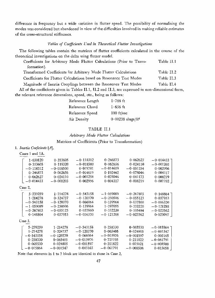
Tables of Coefficients Used in Theoretical Flutter Investigations
The following tables contain the matrices of flutter coefficients calculated in the course of the
theoretical investigations on the delta wing flutter model.
Coefficients for Arbitrary Mode Flutter Calculations (Prior to Trans- Table 11.1
formation).
Transformed Coefficients for Arbitrary Mode Flutter Calculations Table II.2
Coefficients for Flutter Calculations based on Resonance Test Modes Table 11.3
Magnitude of Inertia Couplings between the Resonance Test Modes Table II.4
All of the coefficients given in Tables 11.1, II.2 and 11.3, are expressed in non-dimensional form,
the relevant reference dimensions, speed, etc., being as follows:
Reference Length 1 ·788 ft
Reference Chord 1·656 ft
Reference Speed 100 ftjsec
Air Density 0·00238 slugsjft"
TABLE ILl
Arbitrary Mode Flutter Calculations
Matrices of Coefficients (Prior to Transformation)
II. Flutter and Vibration, Materials, Miscellaneous, Navigation, Parachutes, Performance, Plates andPanels, Stability, Structures, Test Equipment, Wind Tunnels. 845. (post 25. 6d.)
J945 Vol. I. Aero and Hydrodynamics, Aerofoils, 130S. (post 3S.)Vol. II. Aircraft, Airscrews, Controls. 130S. (post 3s.)Vol. III. Flutter and Vibration, Instruments, Miscellaneous, Parachutes, Plates and Panels, Propulsion.
1946 Vol. I. Accidents, Aerodynamics, Aerofoils and Hydrofoils. 168s. (post 3S. 3d.)Vol. II. Airscrews, Cabin Cooling, Chemical Hazards, Controls, Flames, Flutter, Helicopters, Instruments and
1947 Vol. I. Aerodynamics, Aerofoils, Aircraft. 168s. (post 3S. 3d.)Vol. II. Airscrews and Rotors, Controls, Flutter, Materials, Miscellaneous, Parachutes, Propulsion, Seaplanes,
Stability, Structures, Take-off and Landing. 168s. (post 3S. 3d.)
Special VolumesVol. I. Aero and Hydrodynamics, Aerofoils, Controls, Flutter, Kites, Parachutes, Performance, Propulsion,
Stability. 126s. (post 2S. 6d.)Vol. II. Aero and Hydrodynamics, Aerofoils, Airscrews, Controls, Flutter, Materials, Miscellaneous, Parachutes,
Propulsion, Stability, Structures. 147S. (post 2S. 6d.)Vol. III. Aero and Hydrodynamics, Aerofoils, Airscrews, Controls, Flutter, Kites, Miscellaneous, Parachutes,
Propulsion, Seaplanes, Stability, Structures, Test Equipment. J89S. (post 3s. 3d.)
Reviews of the Aeronautical Research Council1939-48 3S. (post Sd.) 1949-54 5s. (post 5d.)
Index to all Reports and Memoranda published in the Annual Technical Reports1909-1947 R. & M. 2600 6s. (post 2d.)
Indexes to the Reports and Memoranda of the Aeronautical Research CouncilBetween Nos. 2351-2449 R. & M. No. 2450 2S. (post 2d.)Between Nos. 2451-2549 R. & M. No. 2550 25. 6d. (post 2d.)Between Nos. 2551-2649 R. & M. No. 2650 2S. 6d. (post 2d.)Between Nos. 2651-2749 R. & M. No. 2750 2S. 6d. (post 2d.)Between Nos. 275J-2849 R. & M. No. 2850 2S. 6d. (post 2d.)Between Nos. 2851-2949 R. & M. No. 2950 3s. (post 2d.)Between Nos. 2951-3049 R. & M. No. 3°50 3s. 6d. (post 2d.)
HER MAJESTY'S STATIONERY OFFICE/rom the addresses overleaf