WING WEIGHT ESTIMATION METHODOLOGY FOR HIGHLY NON- PLANAR LIFTING SYSTEMS DURING CONCEPTUAL DESIGN A. Spohr J. Schirra, J. Hoefling, A. Schedl FH Aachen University of Applied Sciences Flight Systems, Flight Guidance and Control 52064 Aachen, Germany ABSTRACT Unconventional and especially highly non-planar aircraft configurations are supposed to contribute to a significant increase in efficiency of civil air transport vehicles. So called multidisciplinary design optimization tools are used to find an optimum concerning aerodynamic, flight mechanic and structural performance but traditional methods to estimate the wing weight of the lifting system are not always applicable to highly non-planar configurations. For this reason a wing weight estimation tool is developed that combines the advantages of existing methods to achieve high physical accuracy while reducing the computational effort simultaneously. The approach proposed in this paper unites classical analytical methods with simple FEM models to exclude the dependency on statistical sets of data. A simplified beam model of the structural wing box is used to determine the inner forces and moments caused by outer airloads. Based on these inner loads the cross sections are designed by the use of analytical equations. During this process the cross-sectional area is minimized by an automated algorithm while limiting the occurring stresses to a given maximum stress level. Two validations are performed subsequently including one conventional and one unconventional highly non-planar lifting system. NOMENCLATURE A Cross sectional area [m²] a Width of 1 st reinforcement [m] b Width of 2 nd reinforcement [m] c Height of 1 st reinforcement [m] d Height of 2 nd reinforcement [m] FoS Factor of safety [-] Shear force in x-direction [N] Normal force in y-direction [N] Shear force in z-direction [N] h Height of the structural wing box [m] Second moment of inertia along x-axis [m 4 ] Second moment of inertia along z-axis [m 4 ] Mixed moment of inertia [m 4 ] Bending moment along x-axis [Nm] Torsional moment along y-axis [Nm] Bending moment along z-axis [Nm] First moment of inertia along x-axis [m³] First moment of inertia along z-axis [m³] t Thickness [m] w Width of the structural wing box [m] Normal stress [MPa] Shear stress [MPa] Subscript all allowable b bending encl enclosed n normal sk skin sp spar vM von Mises 1. INTRODUCTION Unconventional aircraft configurations like the Box Wing, Joined Wing aircraft or C-Wings are supposed to contribute to a significant improvement of efficiency in civil air transport. Provided with aerodynamic benefits due to low induced drag these configurations might have drawbacks concerning flight mechanics and structural weight in comparison to conventional cantilever wings. So called multidisciplinary design optimization (MDO) tools are often used for weighing up the advantages and disadvantages of promising configurations. With these tools several disciplines like aerodynamics, structural mechanics and flight mechanics are combined and coupled by performance requirements to find the optimal solution. Since this procedure is done in the conceptual design phase, the used models are kept as simple as possible and as accurate as necessary to minimize the computational effort. The student hosted research project Advanced Aircraft Configuration is dealing with the investigation and development of unconventional aircraft configurations and has set itself the task to develop such a MDO tool. For the structural module high-fidelity FEM approaches do not make sense during this early design stage but simple methods for estimating the structural mass of the lifting system are appropriate. A suitable approach to do so is proposed in this paper. 1.1. Empirical methods based on statistics During the last decades several well-engineered methods were developed for conventional cantilever wings which are common use in aircraft industry during the conceptual design phase. Since these methods mostly rely on statistical data of existing aircraft, they are not applicable to unconventional configurations or highly non-planar Deutscher Luft- und Raumfahrtkongress 2013 DocumentID: 301281 1
Transcript
WING WEIGHT ESTIMATION METHODOLOGY FOR HIGHLY NON-PLANAR LIFTING SYSTEMS DURING CONCEPTUAL DESIGN
A. Spohr J. Schirra, J. Hoefling, A. Schedl
FH Aachen University of Applied Sciences Flight Systems, Flight Guidance and Control
52064 Aachen, Germany
ABSTRACT
Unconventional and especially highly non-planar aircraft configurations are supposed to contribute to a significant increase in efficiency of civil air transport vehicles. So called multidisciplinary design optimization tools are used to find an optimum concerning aerodynamic, flight mechanic and structural performance but traditional methods to estimate the wing weight of the lifting system are not always applicable to highly non-planar configurations. For this reason a wing weight estimation tool is developed that combines the advantages of existing methods to achieve high physical accuracy while reducing the computational effort simultaneously. The approach proposed in this paper unites classical analytical methods with simple FEM models to exclude the dependency on statistical sets of data. A simplified beam model of the structural wing box is used to determine the inner forces and moments caused by outer airloads. Based on these inner loads the cross sections are designed by the use of analytical equations. During this process the cross-sectional area is minimized by an automated algorithm while limiting the occurring stresses to a given maximum stress level. Two validations are performed subsequently including one conventional and one unconventional highly non-planar lifting system.
NOMENCLATURE
A Cross sectional area [m²]
a Width of 1st reinforcement [m]
b Width of 2nd
reinforcement [m]
c Height of 1st reinforcement [m]
d Height of 2nd
reinforcement [m]
FoS Factor of safety [-]
𝐹𝑥 Shear force in x-direction [N]
𝐹𝑦 Normal force in y-direction [N]
𝐹𝑧 Shear force in z-direction [N]
h Height of the structural wing box [m]
𝐼𝑥 Second moment of inertia along x-axis [m4]
𝐼𝑧 Second moment of inertia along z-axis [m4]
𝐼𝑥𝑧 Mixed moment of inertia [m4]
𝑀𝑥 Bending moment along x-axis [Nm]
𝑀𝑦 Torsional moment along y-axis [Nm]
𝑀𝑧 Bending moment along z-axis [Nm]
𝑆𝑥 First moment of inertia along x-axis [m³]
𝑆𝑧 First moment of inertia along z-axis [m³]
t Thickness [m]
w Width of the structural wing box [m]
𝜎 Normal stress [MPa]
𝜏 Shear stress [MPa]
Subscript
all allowable
b bending
encl enclosed
n normal
sk skin
sp spar
vM von Mises
1. INTRODUCTION
Unconventional aircraft configurations like the Box Wing, Joined Wing aircraft or C-Wings are supposed to contribute to a significant improvement of efficiency in civil air transport. Provided with aerodynamic benefits due to low induced drag these configurations might have drawbacks concerning flight mechanics and structural weight in comparison to conventional cantilever wings. So called multidisciplinary design optimization (MDO) tools are often used for weighing up the advantages and disadvantages of promising configurations. With these tools several disciplines like aerodynamics, structural mechanics and flight mechanics are combined and coupled by performance requirements to find the optimal solution. Since this procedure is done in the conceptual design phase, the used models are kept as simple as possible and as accurate as necessary to minimize the computational effort.
The student hosted research project Advanced Aircraft Configuration is dealing with the investigation and development of unconventional aircraft configurations and has set itself the task to develop such a MDO tool. For the structural module high-fidelity FEM approaches do not make sense during this early design stage but simple methods for estimating the structural mass of the lifting system are appropriate. A suitable approach to do so is proposed in this paper.
1.1. Empirical methods based on statistics
During the last decades several well-engineered methods were developed for conventional cantilever wings which are common use in aircraft industry during the conceptual design phase. Since these methods mostly rely on statistical data of existing aircraft, they are not applicable to unconventional configurations or highly non-planar
Deutscher Luft- und Raumfahrtkongress 2013DocumentID: 301281
1
lifting systems. Over-determined systems like Box Wing or Joined Wing aircraft may moreover induce specific inner load distributions which are not taken into account by traditional formulas developed for cantilever wings. A very famous approach for example has been presented by Torenbeek [1]. His formula for estimating the wing weight during early design stages unites several factors of influence like the aspect ratio, relative thickness and the wing area with constant factors based on statistics from existing aircraft.
1.2. Double plate model
More suitable methods like the double plate model are capable of taking load distributions of over-determined lifting systems into consideration, but the design is restricted to pure bending along one axis while shear forces and torsion are neglected completely (see Leoviriyakit [2]). The basis for this method is the calculation of the inner bending moments according to the outer loads. Analytical or simple computer codes are commonly used for that. In a second step the cross section of the structural wing box is assumed to consist of two plates, one at the upper and the other one at the lower side of the box (see Figure 1.1 (b)).
Figure 1.1: Double plate model acc. to Leoviriyakit [2]
The vertical distance 𝑡 between the plates and the width 𝑐𝑠 are given by the dimensions of the airfoil and thus the skin thickness 𝑡𝑠 , which is same for both plates is the only
design variable remaining. The inner bending moment resulting from the lift distribution is split into a pair of forces which are acting on the two plates causing normal stresses. By rearranging equation (1) and defining a maximum allowable stress level the required skin thickness 𝑡𝑠 can be evaluated for every cross section.
σ = 𝑀
𝑡 ∙ 𝑡𝑠 ∙ 𝑐𝑠
(1)
The associated cross-sectional areas as well as the total weight of the simplified structural wing box can be estimated subsequently. This method is very simple but the actual load situation is simplified significantly and many effects are neglected.
1.3. Equivalent beam model
To account for oblique bending, shear forces and torsional moments more accurate methods for example by Hajela et al. [3] were developed, still being suitable for unconventional highly non-planar configurations. The
actual wing structure is replaced by equivalent beam models with more accurate cross-sections than in the double plate model (see Figure 1.2). In contrast to the approach presented in chapter 1.2 the shape of the cross-section is more detailed and can account for more complex load cases. The overall mass of the structural wing box is estimated by designing all sections according to the inner loads with a given maximum stress and summing up the masses of the needed material.
Figure 1.2: Cross section according to Hajela et al. [3]
1.4. Synthesis of advantages
In this paper several approaches of existing methods are combined to exploit their advantages for developing a wing weight estimation tool especially for highly non-planar lifting systems. In contrast to some existing methods (see Kroo et al. [4]) the proposed approach assumes that the cross-sectional faces have to carry all occurring loads simultaneously which is close to reality. Hence, a rectangular cross section with reinforcements in the corners is preferred and the cross section is considered with its real shape instead of smearing and simplifying the material distribution like mentioned for example in Bindolino et al. [5]. Although no full size FEM analyses of the wing box is done, a simple FEM approach for a beam model is needed to derive the inner forces and moments based on the outer airloads. Thereby it is only necessary to divide simple line models into a finite number of elements instead of a time consuming meshing process for complex geometries. Basically the main task of the proposed tool is the design of the structural wing box which has to carry the loads. Estimating the masses of secondary structures like the control systems, fuel systems and additional aerodynamic shapes is not in the focus of the paper, but proven approaches are existing as for example stated in Gallman et al. [6] and Samuels [7].
Deutscher Luft- und Raumfahrtkongress 2013
2
2. METHODOLOGY
2.1. Summary of existing methods
The shared objective of all existing methods presented in chapter 1 or proposed by Bindolino et al. [5] or Seywald [8] is to reduce the cross-sectional area while limiting all occurring stresses to the maximum allowed stress; the so called fully stressed design (see Hajela et al. [3] and Gallman et al. [6]). Additional constraints concerning the maximum displacement, aeroelastic effects and minimum gauge thickness are usually part of the optimization. The suitability for unconventional configurations and associated effects like oblique bending is given by using asymmetric reinforcements in the corners of the wing box (see Figure 2.1) and appropriate models for calculating the inner loads.
Figure 2.1: Asymmetric material distribution of a Joined Wing according to Hajela et al. [3]
In the case of over-determined configurations like Joined Wings or Box Wing configurations, the inner load distribution depends on the stiffness distribution as mentioned in Kroo et al. [4] and Gallman et al. [6]. The stiffness distribution in turn depends on the cross-sectional area and its distribution. Thus a straight forward procedure is not possible and an iterative approach becomes unavoidable. An initial stiffness value has to be estimated somehow to start the iteration with a first set of inner loads. Based on that, a more reliable stiffness distribution can be evaluated due to the cross-sectional design.
All methods developed during the last decades differ concerning their level of accuracy, individual assumptions, design variables and cross-sectional shape. In Kroo et al. [4] for example, bending and shear effects are decoupled in a way that the skins carry shear and torsional loads only. The bending loads have to be absorbed by the spars and the rectangular reinforcements in the corners. The representation of the cross-sectional shape varies from simple rectangular plates to more realistic versions with stiffeners and lumped stringers in the corners (see Bindolino et al. [5]).
2.2. General structure of the proposed tool
Since the multidisciplinary design optimization tool including the structural module is part of the conceptual design phase, a compromise between accuracy and simplicity has to be found. Consequently the following requirements were set for the development of the wing weight estimation tool:
Applicability for highly non-planar lifting systems
Suitability for over-determined systems
Consideration of up to two planforms
Low computational effort
No classical FEM analyses of the whole wing box
Waiver of iterative processes as far as possible
Consideration of a minimum gauge thickness
Additionally to these requirements two versions of the tool will be established. These are one stand-alone version with graphical user interface plus graphical output and another release in a black box manner which can be integrated into the MDO tool. To guarantee flexibility, TXT-files are used as input and output files.
The general structure of the tool is depicted in Figure 2.2 and explained in the following.
Figure 2.2: General structure and process of the tool
Deutscher Luft- und Raumfahrtkongress 2013
3
The basis for the wing weight estimation consists of the outer geometry of the lifting system in terms of planform data, general parameters like material properties and the aerodynamic data set. The latter, especially the lift distribution is obtained from a vortex lattice method called LamDes, which has been improved for the demands of highly non-planar lifting systems (see Spohr [9]). Due to the flexibility of the TXT-file as input format other codes can be used instead easily after adapting the output format.
The resulting set of data is read into the Preprocessor
where the airloads are calculated according to the given lift distribution. Drag forces are comparably low and are thus neglected at the moment but can be considered easily in future versions. The flight state including things like the load factor and the flight velocity is also taken into account in this module. The planform coordinates together with positioning data for front and rear spar lead to the location of the actual structural wing box and its centerline. This centerline is divided into a finite number of elements according to a suitable element size which can be chosen by the user. Due to the fact that the resulting aerodynamic loads are acting approximately at the quarter chord line, a lever arm to the centerline of the structural wing box arises. The resulting moment along the global y-axis is also computed in this module.
After transferring the data to the FEM line model the inner forces and moments are calculated based on a classical FEM beam approach. Since the FEM model does not have to handle a complex geometry but only a line which is located in the three dimensional space, the computational effort is desirable low. For statically determined systems the influence of the cross-sectional area and thus of the stiffness cancels out and a straight forward calculation becomes possible. In contrast to that an iteration loop with initial stiffness estimation is
necessary for any over-determined lifting system.
The next step of the tool is the Cross section design module on which this paper is focused. Here the inner forces and moments are used to calculate the necessary cross-sectional area and its distribution to keep all occurring stresses below a given limit. Basically a two dimensional design is performed for every cross section, which is completely independent of the type of static specification of the system. Since the inner forces and moments of over-determined systems depend on their stiffness distribution (see Kroo et al. [4] and Gallman et al. [6]) an iteration loop becomes necessary. At the beginning
a stiffness distribution is estimated based on the minimum gauge thickness. The resulting inner forces and moments lead to more realistic cross-sectional areas and therefore stiffnesses. This process including the FEM line model and the cross section design module is repeated until
convergence is reached.
After computing the needed cross-sectional areas a Postprocessor module is used to calculate the actual wing weight. Therefore the average cross-sectional area within one section is multiplied by the according element length and at the end the sum is multiplied by the density of the used material to obtain the mass. For the stand-alone version graphical outputs in terms of diagrams and tables showing the needed areas and the shape of the reinforcements are generated. In addition it is possible to activate an interface to CATIA V5 that consists of an Excel sheet with embedded VBA macro. The macro is capable of exporting the vertices to the CAD environment and to connect them by polylines automatically. Finally the user can decide if the macro is supposed to create a solid body of the whole structural wing box based on the polylines.
2.3. Cross section design module
The task of the cross section design module in particular is to lay out the material distribution in every cross section according to the inner forces and moments. Figure 2.3 shows the general shape of each cross section and how it is located within the airfoil.
Figure 2.3: Structural wing box within a Joined Wing configuration
Deutscher Luft- und Raumfahrtkongress 2013
4
Figure 2.4: Cross section with rectangular reinforcements
Figure 2.5: Cross section with triangular reinforcements
While the outer dimensions width and height are given by the preprocessor according to chord length and airfoil thickness, all other parameters are determined by the design module. The thickness of front and rear spar, sometimes also called webs and the size of the upper and lower skin (also: caps) is the same at front and rear respectively at the upper and lower side. Similar to that the rectangular reinforcement in the upper right corner has the same size as the one in the lower left corner. Same holds for lower right and upper left corner (see Figure 2.4). Thereby point symmetry around the center is achieved and asymmetric material distributions are still possible. As coordinate system the aircraft fixed system is used and the cuts through the wing are oriented parallel to the global x-axis.
The shape described above is not ideal for a practical implementation because of its sharp corners and the involved notch effects. Despite the simple mathematical description of the rectangles a more appropriate design with triangular reinforcements in the corners as depicted in Figure 2.5 is established in addition. The proposed tool performs an optimization with rectangular and triangular reinforcements and the comparison of the resulting wing weights leads to the lighter solution. It is ensured that either all reinforcements are rectangular or triangular but changes from one cross section to the next one are prevented.
For determining suitable values for all six parameters (𝑡𝑠𝑝𝑎𝑟 , 𝑡𝑠𝑘𝑖𝑛 , 𝑎, 𝑏, 𝑐, 𝑑) they have to be chosen in a way that
all occurring stresses are below the given limit. Since there is an endless number of possible designs, which would ensure that, additional constraints are necessary to achieve the most effective material distribution. Thus an optimization algorithm is chosen to minimize the cross-sectional area while constraining the maximum occurring stresses. Unfortunately it is not possible to avoid the iterative process here, so it has to be ensured that the optimization results are all valid and that the process is working as fast and effectively as possible. Therefore simplified formulas are used to estimate appropriate starting values for spar and skin thickness and for the four reinforcement variables. For this estimation it is assumed that all reinforcements are quadratic and have the same size which leads to an axisymmetric structure. Another simplification hypothesizes that the skins and spars have to carry shear stresses only and the bending moment is absorbed by the reinforcements. Without decoupling both effects the dependency inbetween would allow for more than one possible solution and more complex formulas would become necessary.
An integrated sub module of the algorithm calculates all occurring stresses according to the given analytical formulas. Based on that, the combined von Mises stress is calculated along the spar and the skin which has to be lower than the maximum allowed tensile stress of the material divided by a factor of safety. This iterative process is repeated until the needed cross-sectional area reaches a minimum while fulfilling the maximum stress criteria. The individual formulas and calculation steps are explained in the following.
First of all the inertias are evaluated according to the equations (2), (3) and (4).
𝐼𝑥(𝑧) = 𝑧2 𝑑𝐴𝐴
(2)
𝐼𝑧(𝑥) = 𝑥2 𝑑𝐴𝐴
(3)
𝐼𝑥𝑧 = − x ∙ z 𝑑𝐴𝐴
(4)
Then the normal stresses due to bending moments along the x- and z-axes are determined by using the formula for oblique bending:
𝜎𝑦𝑏 = 1
∆ 𝑀𝑥𝐼𝑧 − 𝑀𝑧𝐼𝑥𝑧 ∙ 𝑧 − 𝑀𝑧𝐼𝑥 − 𝑀𝑥𝐼𝑥𝑧 ∙ 𝑥 (5)
with
∆ = 𝐼𝑥𝐼𝑧 − 𝐼𝑥𝑧2 (6)
The resulting stresses for both a moment along x and z show a linear distribution with its climax in two opposite corners and its minimum in the other two corners.
The influence of normal tensile or compressive loads is evaluated by dividing the acting force by the cross-sectional area of the respective section (see equation (7)). Superposition of all stresses acting normal to the section in y-direction leads to the resulting normal stresses.
𝜎𝑦𝑛 = 𝐹𝑦
𝐴 (7)
Deutscher Luft- und Raumfahrtkongress 2013
5
The occurring shear stresses are also caused by two different effects. First of all, shear forces in x- and z-direction are leading to shear stresses in the skins and spars. The equations (8) and (9) are used to calculate the distribution of the first moment of area, which looks similar to that depicted in Figure 2.6 for a force in only one direction (Note: the positive y-direction in the figure corresponds to the negative x-direction used in the tool). The actual distribution for the shape used in this tool shows additional kinks near the locations where the reinforcements begin or end respectively (see Figure 2.7).
𝑆𝑥(𝑧) = 𝑧 𝑑𝐴𝐴
(8)
𝑆𝑧(𝑥) = 𝑥 𝑑𝐴𝐴
(9)
Figure 2.6: Principle Shear flow in thin-walled rectangle (extracted from Lenz [10])
Figure 2.7: Qualitative depiction of the shear flow in one half of the cross section
Based on that, the resulting shear stresses can be determined according to equation (10) and equation (11).
𝜏𝑦 = 𝐹𝑥 ∙ 𝑆𝑧
𝐼𝑧 ∙ 𝑡 (10)
𝜏𝑦 = 𝐹𝑧 ∙ 𝑆𝑥
𝐼𝑥 ∙ 𝑡 (11)
Secondly shear stresses are caused by the torsional moment along the y-axis. Applying Bredt’s first formula
(Equation (12)) for thin walled cross sections leads to a constant shear flow along the perimeter and in combination with the local thickness, the actual shear stress at every location can be determined.
𝜏𝑡(𝑠) = 𝑀𝑦
2 ∙ 𝐴𝑒𝑛𝑐𝑙 ∙ 𝑡(𝑠) (12)
Since the location of the maximum normal stress does not match necessarily with the location of maximum shear stress, the perimeter of the cross section is divided into a
Deutscher Luft- und Raumfahrtkongress 2013
6
finite number of points. The combined von Mises stress is then derived at every single point to find the critical spot.
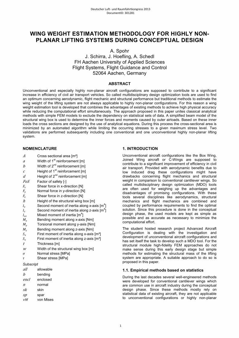
For the spars the normal stress in y-direction and the shear stress in z-direction are decisive to calculate the according combined von Mises stress (see equation (13)).
𝜎𝑣𝑀 𝑠𝑝𝑎𝑟 = 𝜎𝑦2 + 3 ∙ 𝜏𝑦𝑧
2 (13)
For the skins the normal stress in y-direction and the shear component in x-direction are relevant (see equation (14)).
𝜎𝑣𝑀 𝑠𝑘𝑖𝑛 = 𝜎𝑦2 + 3 ∙ 𝜏𝑦𝑥
2 (14)
Taking advantage of the point symmetry the maximum of the von Mises stress distribution is evaluated in only four different sections to ensure that all other occurring stresses are below the given limit. Considering the right half of the cross-sectional shape in Figure 2.7, drawn in solid black, the four sections are:
Upper skin, right half
Right spar, upper half
Right spar, lower half
Lower skin, right half
In all of these sections the maximum von Mises stress is computed and set equal to the limit:
𝜎𝑣𝑀 𝑚𝑎𝑥 = 𝜎𝑎𝑙𝑙
𝐹𝑜𝑆 (15)
Especially near the wing tip the inner forces and moments can be that low that even a cross section with minimum gauge thickness would resist the loads, with the maximum occurring stress being significantly below the limit. Therefore an upstream process stage verifies if the minimum material application is sufficient. If this is not the case, the normal algorithm is used to scale the reinforcements and spar and skin thicknesses.
In addition to the maximum stress constraint, further conditions limit the range of values for the six design variables (𝑡𝑠𝑝𝑎𝑟 , 𝑡𝑠𝑘𝑖𝑛 , 𝑎, 𝑏, 𝑐, 𝑑). The lower boundaries for
skin and spar thickness are set to minimum gauge thickness and the parameters of the reinforcements have to be greater or equal to zero. The upper boundaries are set quite loose, just excluding unrealistic values. More important is the definition of the linear inequalities shown in equation (16).
This set of equations prevents the algorithm from choosing values for the design variables that would cause an overlapping of reinforcements or reinforcements being too large to fit into the wing box.
The optimization process is stopped automatically if the relative change in cross-sectional area falls below a given threshold. At the same time the constraint violation and thus the stress deviation has to be lower than an accuracy parameter preset by the user.
3. VALIDATION
3.1. Planar lifting system: Boeing 727
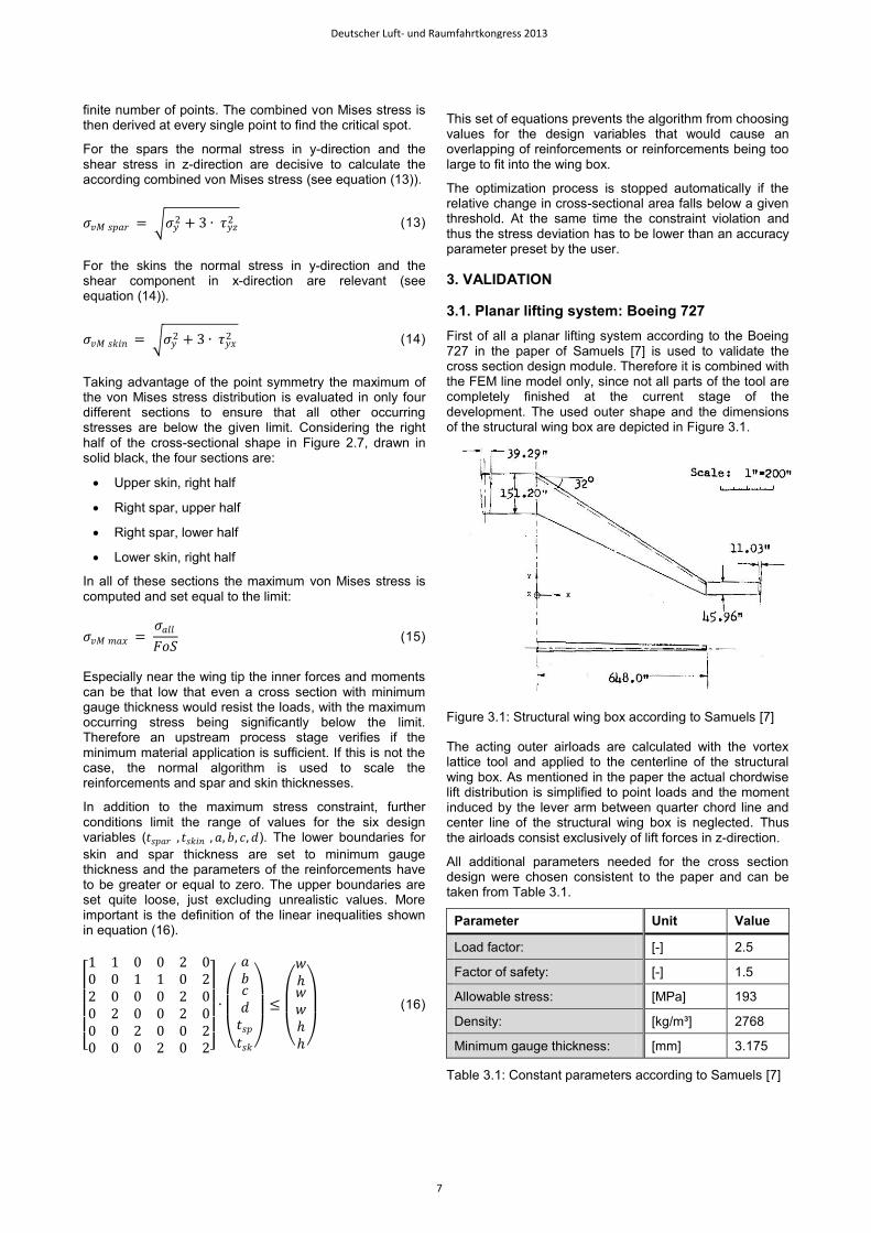
First of all a planar lifting system according to the Boeing 727 in the paper of Samuels [7] is used to validate the cross section design module. Therefore it is combined with the FEM line model only, since not all parts of the tool are completely finished at the current stage of the development. The used outer shape and the dimensions of the structural wing box are depicted in Figure 3.1.
Figure 3.1: Structural wing box according to Samuels [7]
The acting outer airloads are calculated with the vortex lattice tool and applied to the centerline of the structural wing box. As mentioned in the paper the actual chordwise lift distribution is simplified to point loads and the moment induced by the lever arm between quarter chord line and center line of the structural wing box is neglected. Thus the airloads consist exclusively of lift forces in z-direction.
All additional parameters needed for the cross section design were chosen consistent to the paper and can be taken from Table 3.1.
Parameter Unit Value
Load factor: [-] 2.5
Factor of safety: [-] 1.5
Allowable stress: [MPa] 193
Density: [kg/m³] 2768
Minimum gauge thickness: [mm] 3.175
Table 3.1: Constant parameters according to Samuels [7]
Deutscher Luft- und Raumfahrtkongress 2013
7
The execution of the FEM line model leads to shear forces in z-direction, a bending moment distribution along the global x-axis and a torsional moment along the global y-axis as shown in Figure 3.2 and Figure 3.3.
Figure 3.2: Inner force distribution
Figure 3.3: Inner moment distribution
Based on the inner forces and moments the cross-sectional areas with its reinforcements are designed accordingly which leads to a total mass of the structural wing box of 2280 𝑘𝑔 for one wing. Compared to the
2303 𝑘𝑔 evaluated by Samuels this value is slightly lower
but a relative error of −1 % is more than acceptable.
The resulting structural wing box with its cross sections is depicted in Figure 3.4 showing the outer contours in black while representing the inner cut-outs in grey. All sections are axisymmetric which is in great accordance to the fact that only bending moments along the x-axis are acting and thus no oblique bending effects are present.
Figure 3.4: Representation of the structural wing box
The distribution of the cross-sectional area needed to resist the loads, is depicted in Figure 3.5. The trend line is descending towards the wing tip which is in accordance with the loads but the distribution is not as smooth as expected. Additionally some irregularities occur concerning the use of reinforcements. In some sections large reinforcements are present, while other cross sections are designed nearly without any reinforcements. Possibly more than one solution can be found satisfying the maximum stress constraint but the reason for that is not clarified completely and the effect will be investigated in future work.
Figure 3.5: Distribution of cross-sectional area
3.2. Non-planar lifting system: Joined Wing
Since there is no Joined Wing or Box Wing configuration ever built in the size of a transport aircraft, no data sets are available for validating against existing aircraft. Thus a Joined Wing according to the paper of Miura et al. [11] is chosen to prove the capabilities of the proposed wing weight estimation tool in terms of highly non-planar configurations. The used outer geometry and its dimensions are depicted in Figure 3.6 and Figure 3.7.
Figure 3.6: Topview of the Joined Wing configuration
-6.0E+05
-5.0E+05
-4.0E+05
-3.0E+05
-2.0E+05
-1.0E+05
0.0E+00
0 0.2 0.4 0.6 0.8 1
Inn
er
Fo
rce [
N]
Relative spanwise position [-]
FxFyFz
-3.0E+06
-2.0E+06
-1.0E+06
0.0E+00
1.0E+06
2.0E+06
3.0E+06
4.0E+06
0 0.2 0.4 0.6 0.8 1
Inn
er
Mo
men
t [N
m]
Relative spanwise position [-]
MxMyMz 0.0E+00
2.0E+04
4.0E+04
6.0E+04
8.0E+04
1.0E+05
1.2E+05
1.4E+05
1.6E+05
0 0.2 0.4 0.6 0.8 1
Cro
ss-s
ecti
on
al are
a [
mm
²]
Relative spanwise position [-]
Deutscher Luft- und Raumfahrtkongress 2013
8
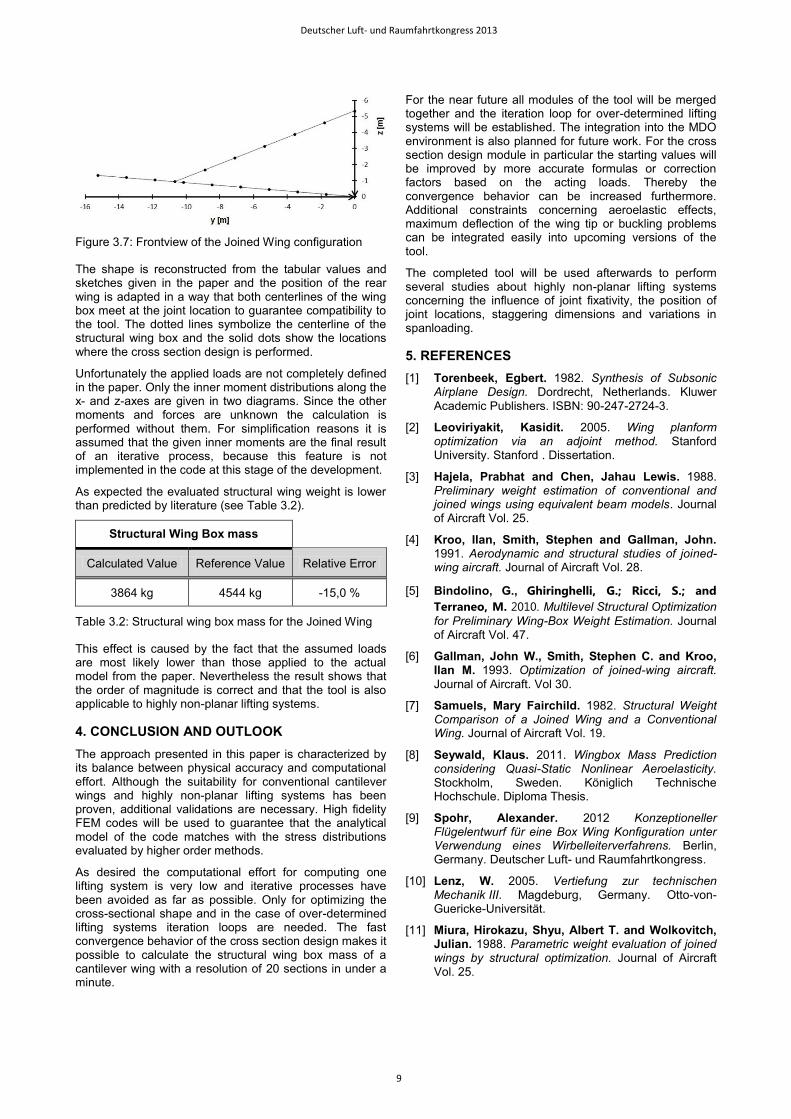
Figure 3.7: Frontview of the Joined Wing configuration
The shape is reconstructed from the tabular values and sketches given in the paper and the position of the rear wing is adapted in a way that both centerlines of the wing box meet at the joint location to guarantee compatibility to the tool. The dotted lines symbolize the centerline of the structural wing box and the solid dots show the locations where the cross section design is performed.
Unfortunately the applied loads are not completely defined in the paper. Only the inner moment distributions along the x- and z-axes are given in two diagrams. Since the other moments and forces are unknown the calculation is performed without them. For simplification reasons it is assumed that the given inner moments are the final result of an iterative process, because this feature is not implemented in the code at this stage of the development.
As expected the evaluated structural wing weight is lower than predicted by literature (see Table 3.2).
Structural Wing Box mass
Calculated Value Reference Value Relative Error
3864 kg 4544 kg -15,0 %
Table 3.2: Structural wing box mass for the Joined Wing
This effect is caused by the fact that the assumed loads are most likely lower than those applied to the actual model from the paper. Nevertheless the result shows that the order of magnitude is correct and that the tool is also applicable to highly non-planar lifting systems.
4. CONCLUSION AND OUTLOOK
The approach presented in this paper is characterized by its balance between physical accuracy and computational effort. Although the suitability for conventional cantilever wings and highly non-planar lifting systems has been proven, additional validations are necessary. High fidelity FEM codes will be used to guarantee that the analytical model of the code matches with the stress distributions evaluated by higher order methods.
As desired the computational effort for computing one lifting system is very low and iterative processes have been avoided as far as possible. Only for optimizing the cross-sectional shape and in the case of over-determined lifting systems iteration loops are needed. The fast convergence behavior of the cross section design makes it possible to calculate the structural wing box mass of a cantilever wing with a resolution of 20 sections in under a minute.
For the near future all modules of the tool will be merged together and the iteration loop for over-determined lifting systems will be established. The integration into the MDO environment is also planned for future work. For the cross section design module in particular the starting values will be improved by more accurate formulas or correction factors based on the acting loads. Thereby the convergence behavior can be increased furthermore. Additional constraints concerning aeroelastic effects, maximum deflection of the wing tip or buckling problems can be integrated easily into upcoming versions of the tool.
The completed tool will be used afterwards to perform several studies about highly non-planar lifting systems concerning the influence of joint fixativity, the position of joint locations, staggering dimensions and variations in spanloading.
[2] Leoviriyakit, Kasidit. 2005. Wing planform optimization via an adjoint method. Stanford University. Stanford . Dissertation.
[3] Hajela, Prabhat and Chen, Jahau Lewis. 1988. Preliminary weight estimation of conventional and joined wings using equivalent beam models. Journal of Aircraft Vol. 25.
[4] Kroo, Ilan, Smith, Stephen and Gallman, John. 1991. Aerodynamic and structural studies of joined-wing aircraft. Journal of Aircraft Vol. 28.
[5] Bindolino, G., Ghiringhelli, G.; Ricci, S.; and
Terraneo, M. 2010. Multilevel Structural Optimization
for Preliminary Wing-Box Weight Estimation. Journal of Aircraft Vol. 47.
[6] Gallman, John W., Smith, Stephen C. and Kroo, Ilan M. 1993. Optimization of joined-wing aircraft.
Journal of Aircraft. Vol 30.
[7] Samuels, Mary Fairchild. 1982. Structural Weight Comparison of a Joined Wing and a Conventional Wing. Journal of Aircraft Vol. 19.
[8] Seywald, Klaus. 2011. Wingbox Mass Prediction considering Quasi-Static Nonlinear Aeroelasticity. Stockholm, Sweden. Königlich Technische Hochschule. Diploma Thesis.
[9] Spohr, Alexander. 2012 Konzeptioneller Flügelentwurf für eine Box Wing Konfiguration unter Verwendung eines Wirbelleiterverfahrens. Berlin, Germany. Deutscher Luft- und Raumfahrtkongress.
[10] Lenz, W. 2005. Vertiefung zur technischen Mechanik III. Magdeburg, Germany. Otto-von-Guericke-Universität.
[11] Miura, Hirokazu, Shyu, Albert T. and Wolkovitch, Julian. 1988. Parametric weight evaluation of joined wings by structural optimization. Journal of Aircraft Vol. 25.