1 WINMOR Protocol Specification (Beta Release) Revision: 1.0.6 Dec 11, 2009 Rick Muething, KN6KB, AAA9WK 1.0 Scope: This document describes the preliminary WINMOR sound card protocol at the physical and data link levels. It is the complete specification of the WINMOR protocol. It does not address higher level protocol layers. The WINMOR protocol is not proprietary and is released to the public domain. This document describes the 500 Hz and 1600 Hz bandwidth modes using 93.75 Baud (PSK) and 46.875 baud FSK modulation. 2.0 Purpose: The intent of this document is two fold: a) To serve as a working document during protocol development and testing b) To serve as a template to allow others familiar with the art to build compatible drivers that support the data link protocol layer. 3.0 Definitions and Syntax: Several specific terms and syntax are used in this document: Definitions: A term or item is defined using the := symbol. This symbol can be read as is defined as Implementation directives: These are key words that indicate how an item is to be implemented or recommend a method of implementation. They are always indicated by capitalized italic words. These are: MUST := this must be followed to implement the protocol MUST NOT := this must not be done to implement the protocol SHOULD := this is the recommended way to implement the protocol MAY := this is alternative way to implement the protocol. The syntax above is always used to distinguish between the common use of the same words. & is used to indicate catenation. E.g. Frame := Pilot & Data 4.0 Overview of the Protocol: The WINMOR protocol is intended to be used for sending messages and binary data error free over a HF radio link. It is a Selective Repeat Automatic Retry reQuest (SRARQ) protocol where the Information Receiving Station (IRS) acknowledges receipt of the data to the Information Sending Station (ISS). Normally during a connection session the IRS and ISS exchange roles multiple times. The protocol is designed to handle the type conditions normally encountered in amateur radio transmission.
Transcript
1
WINMOR Protocol Specification (Beta Release)
Revision: 1.0.6 Dec 11, 2009
Rick Muething, KN6KB, AAA9WK
1.0 Scope: This document describes the preliminary WINMOR sound card protocol at the physical and data link levels. It is the complete specification of the WINMOR protocol. It does not address higher level protocol layers. The WINMOR protocol is not proprietary and is released to the public domain. This document describes the 500 Hz and 1600 Hz bandwidth modes using 93.75 Baud (PSK) and 46.875 baud FSK modulation.
2.0 Purpose: The intent of this document is two fold: a) To serve as a working document during protocol development and testing b) To serve as a template to allow others familiar with the art to build compatible
drivers that support the data link protocol layer.
3.0 Definitions and Syntax: Several specific terms and syntax are used in this document:
Definitions: A term or item is defined using the := symbol. This symbol can be read as is defined as
Implementation directives: These are key words that indicate how an item is to be implemented or recommend a method of implementation. They are always indicated by capitalized italic words. These are:
MUST := this must be followed to implement the protocol MUST NOT := this must not be done to implement the protocol SHOULD := this is the recommended way to implement the protocol MAY := this is alternative way to implement the protocol. The syntax above is always used to distinguish between the common use of the
same words. & is used to indicate catenation. E.g. Frame := Pilot & Data
4.0 Overview of the Protocol: The WINMOR protocol is intended to be used for sending messages and binary
data error free over a HF radio link. It is a Selective Repeat Automatic Retry reQuest (SRARQ) protocol where the Information Receiving Station (IRS) acknowledges receipt of the data to the Information Sending Station (ISS). Normally during a connection session the IRS and ISS exchange roles multiple times. The protocol is designed to handle the type conditions normally encountered in amateur radio transmission.
2
Specifically:
Generally low S/N levels Non channelized frequencies with interference Poor to moderate propagation conditions including poor multipath environment. Frequency offset (between send and receiver) and drift Sound card sampling rate error and drift
The WINMOR protocol uses basic OFDM (Orthogonal Frequency Division Multiplexing) modulation and a number of modulation modes and error correction schemes to adapt to changing channel conditions. There is currently 2 operating bandwidths of 500 and 1600 Hz (@ 26 db below peak power output: 500 Hz BW 2 carriers 46.875 Baud 4FSK or 93.75 baud PSK using TCM 4PSK, 8PSK or 16PSK
1600 Hz BW 8 carriers 46.875 Baud 4FSK or 93.75 baud PSK using TCM 4PSK, 8PSK or 16PSK
WINMOR is not optimized for keyboarding or chat mode applications though this may be possible with the appropriate user client.
4.1 Error Correcting Mechanisms WINMOR employs a number of powerful error detecting and correcting mechanisms which are specifically adapted to the types of errors found in HF communications using popular FSK and PSK modulation schemes. This section outlines the error correction approach used.
Normally error correction is done in terms of layers for improved effectiveness and efficiency. The following briefly describes these layers and how they are used in WINMOR.
4.1.1. Outer Sumcheck Layer This layer applies a standard CRC sumcheck calculation on the corrected data. It insures to a very high probability that the corrections are indeed correct and the data matches that which was transmitted. For Connect request frames, ID frames and all data frames a 16 bit CRC Polynomial of x^16 + x^12 +x^5 + 1 is used. For short coded control and ACK frames an 8 bit CRC polynomial of x^8 + x^7 +x^3 + x^2 + 1 is used.
4.1.2 Reed Solomon Layer Reed-Solomon (R-S) FEC appends parity blocks (characters) to an uncoded message which are used to detect and correct errors. The total message size (with parity) must be equal to 2n 1 where n is the character size in bits. WINMOR uses a single 8 bit character size. Shortened R-S codes (where sender and receiver agree a priori to the message size and not transmit the fill part of the message) are used as is typical in many R-S applications.
3
For data frames the Reed Solomon layer is actually implemented in two formats. The first format is what is called weak R-S where a relatively few parity characters are appended to the message. This weak R-S format is usually sufficient to correct the frame under most conditions. If a data frame must be repeated (reciever did not ACK) then the second strong R-S format is used which transmits just the parity charactes of a more robust R-S code. These parity characters are then used along with the prior sent data (ignoring the weak R-S Parity bytes) to attempt to correct the original message part of the first weak R-S format. These two formats are alternated with each repeat of a data frame.
4.1.3 Viterbi Encoded TCM Layer The next layer uses what is called Viterbi Encoded Pragmatic Trellis Coded Modulation. (See appendix B) This is used on all PSK modes but is not used on FSK. This scheme reaches to within about .2 db of the theoretical coding gain of the best similar length Trellis codes but uses a standard Viterbi encoder/decoder (NASA Voyager R=1/2, K=7). In TCM a single bit is added to each PSK symbol doubling the number of phases. The gain provided by the code exceeds that lost by the tighter spaced phase constellation by typically about 3 dB giving essentially a 3dB power improvement with no change in payload throughput or bandwidth. The layered use of the Viterbi inner encoding and R-S outer encoding is common in many advanced error correcting schemes.
4.1.4 Memory ARQ The final layer used is what is commonly called memory ARQ (Automatic Retry reQuest). If decoding on the received data using the above layers is not sucessful Memory ARQ averages the received demodulated (soft) symbol values (frequency or phase/magnitude ) on a symbol by symbol basis and attempts a decode (using the above layers) on the averaged values. This can be effective in very weak signal conditions. Memory ARQ is done only for data frames and is applied to both the weak R-S and strong R-S data formats. 5.0 Physical Layer Protocol Description: The protocol requires the following hardware:
1) Radio connection. This SHOULD be a single sideband (SSB) transceiver capable of transmitting Upper sideband low distortion audio in the range of 600-2400Hz. When SSB transmission is used it MUST always done using Upper Sideband (USB). Other modulation schemes (e.g. NBFM) MAY be used in some applications.
2) Radio Frequency accuracy: If SSB modulation is used the radio MUST be able to be set to within +/- 100 Hz of a specific (published) frequency.
3) Frequency Drift: If SSB modulation is used the radio frequency MUST have a short term drift of < .5Hz/Second over any 5 second period.
4) The transceiver MUST have a Receive to transmit switching time of < 100 ms and a Transmit to Receive switching time of < 100 ms
5) The audio for the protocol MAY be generated using a standard PC sound card and appropriate software.
6) On Radios with built in sound card interfaces (e.g. Icom 7200) it is possible to use the radio s built in sound card to send and receive SSB audio.
4
7) The sound card capture device (receiving data) MUST be able to support a real
or interpolated sampling frequency of 48000Hz +/- .1% (+/-1000 ppm) 8) The sound card playback Device (transmitting data) MUST be able to support
a real or interpolated sampling frequency of 12000 Hz +/-.1% (+/- 1000 ppm) 9) The processor or PC used to implement the protocol MUST be able to
complete the decoding of any frame and respond with the appropriate response in 500 ms or less. (this is currently estimated to equate to a Pentium/Celeron class processor of 500 MHz or above) It may be possible to reduce the PC requirement in the future at the expense of session throughput.
6.0 Data Link Layer Protocol Description:
6.1 Definitions: Information Sending Station (ISS) := the station currently sending data to the other station. The ISS MUST only send data or control frames.
Information Receiving Station (IRS) := the station currently receiving data or commands from the other station. The IRS MUST only send Ack or control frames.
Carrier := one of the modulation carriers. There are either 4 or 6 modulation modes supported depending on the desired session bandwidth:
1) 500Hz BW a. Modes: 4PSK TCM, 8PSK TCM, 16PSK TCM 2 Carriers at 1406.25 Hz and 1593.75 Hz b. Mode 4FSK 2 groups of 1of 4 Carriers. (2 carriers active simultaneously)
Group 1: 1312.5, 1358.375, 1406.25 and 1453.125 Hz Group 2: 1546.875, 1593.75, 1640.625 and 1687.5 Hz
2) 1600 Hz BW a. Modes: 8 carrier 4PSK TCM, 8PSK TCM, 16PSK TCM 8 Carriers at 843.75, 1031.25, 1218.75, 1406.25, 1593.75, 1781.25, 1968.75 and 2156.25 Hz b. Mode 8 carrier 4FSK 8 groups of 1of 4 Carriers. (8 carriers active simultaneously)
Group 1: 750.0, 796.875, 843.75 and 890.625 Hz Group 2: 937.5, 984.375, 1031.25 and 1078.125 Hz Group 3: 1125.0, 1171.875, 1218.75 and 1265.625 Hz Group 4: 1312.5, 1358.375, 1406.25 and 1453.125 Hz Group 5: 1546.875, 1593.75, 1640.625 and 1687.5 Hz Group 6: 1734.375, 1781.25, 1828.125 and 1875.0 Hz Group 7: 1921.875, 1968.75, 2015.625 and 2062.5 Hz Group 8: 2109.775, 2156.25, 2203.125 and 2250.0 Hz
c. Modes: 2 carrier 4PSK TCM 2 Carriers at 1406.25 Hz and 1593.75 Hz
d. Mode 2 carrier 4FSK
5
2 groups of 1of 4 Carriers. (2 carriers active simultaneously)
Group 1: 1312.5, 1358.375, 1406.25 and 1453.125 Hz Group 2: 1546.875, 1593.75, 1640.625 and 1687.5 Hz
Pilot := Leader of the Frame. The Pilot is used to enable rapid identification of a transmission, to DSP tune the receiving station accurately, to establish symbol and frame sync and to indicate the frame type. The single carrier of 1500.00 +/- .1% is sent at full modulation strength (Maximum PEP value) to maximize S/N during the Pilot interval
Pilot := Ptun & Pfsync & Pfty Ptun is the tuning pilot. Pfsync is the frame sync identifier. Pfty is the frame type
identifier. Ptun & Pfsync are always sent using single carrier DBPSK modulation with a root raised cosine envelope encoding for robustness.
Ptun := 24 adjacent symbols of the pilot carrier (1500.0 Hz) alternating phase on each symbol. The tuning signal MAY be extended up to 16 symbols (170.66 ms) for transceivers with slow R>T switching or slow VOX PTT response if using VOX. Pfsync := Frame sync symbol consisting of one symbol of the same phase as the immediately preceding Ptun symbol. The Pfsync symbol serves as the frame sync symbol for the following Ptfy symbols. Pfty := 4 sequential 4FSK symbols. These 4 symbols encode the 4 bit frame type with an extended 8,4 hamming code.
Frame := a packet of information. A frame is composed of a Pilot & Data. Frames are identified by the syntax Fxyz where xyz is the frame descriptor.
Symbol := A symbol is one modulation burst of data. The symbol rate is 93.75 symbols per second (baud) +/- .1% for PSK modes (93.75 = 12000/128) . For 4FSK modes the symbol rate is 46.875 symbols per second (baud) +/- .1% (12000/256) Pilot symbols consist of a single carrier with a root raised cosine envelope weighted at the maximum PEP value. Data and control symbols consist of:
1) 2 carrier PSK modulated with a root raised cosine envelope. Each carrier is weighted 53% of the pilot carrier
2) 2 Carrier 4FSK (one of 4 tones). Each carrier is weighted at 50% of the weight of the pilot carrier.
3) 8 simultaneous carriers PSK modulated with a root raised cosine envelope. Each carrier is weighted at 16.7% of the maximum PEP value.
4) 8 simultaneous carriers each 4FSK (one of 4 tones). Each carrier weighted at 14.3% of the maximum PEP value.
(Note: these carrier weightings are combined with limited soft and hard clipping to reduce the crest factor. The percentages above are subject to change.
For PSK modes the initial symbol following the Pilot is the reference symbol Sr. This establishes the reference for the next Differential symbol. The Sr symbol carries no
6
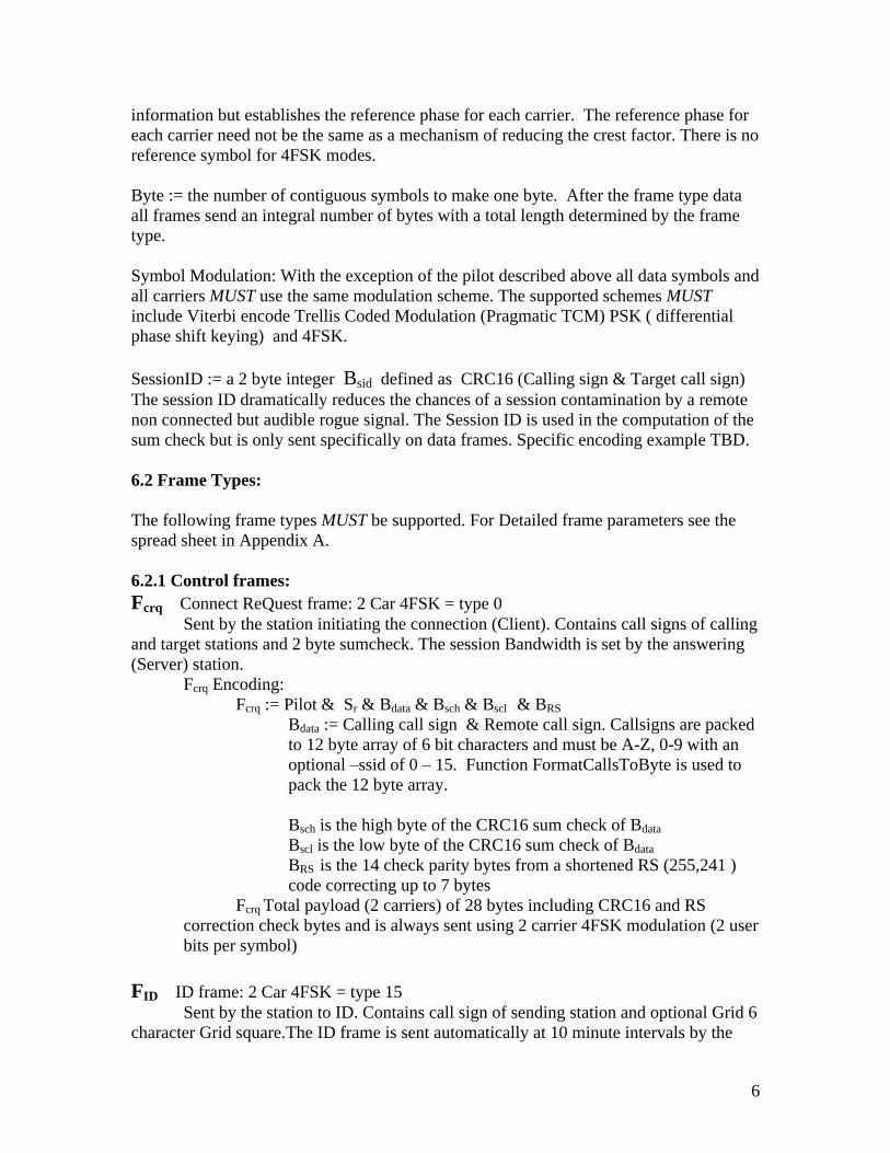
information but establishes the reference phase for each carrier. The reference phase for each carrier need not be the same as a mechanism of reducing the crest factor. There is no reference symbol for 4FSK modes.
Byte := the number of contiguous symbols to make one byte. After the frame type data all frames send an integral number of bytes with a total length determined by the frame type.
Symbol Modulation: With the exception of the pilot described above all data symbols and all carriers MUST use the same modulation scheme. The supported schemes MUST include Viterbi encode Trellis Coded Modulation (Pragmatic TCM) PSK ( differential phase shift keying) and 4FSK.
SessionID := a 2 byte integer Bsid defined as CRC16 (Calling sign & Target call sign) The session ID dramatically reduces the chances of a session contamination by a remote non connected but audible rogue signal. The Session ID is used in the computation of the sum check but is only sent specifically on data frames. Specific encoding example TBD.
6.2 Frame Types:
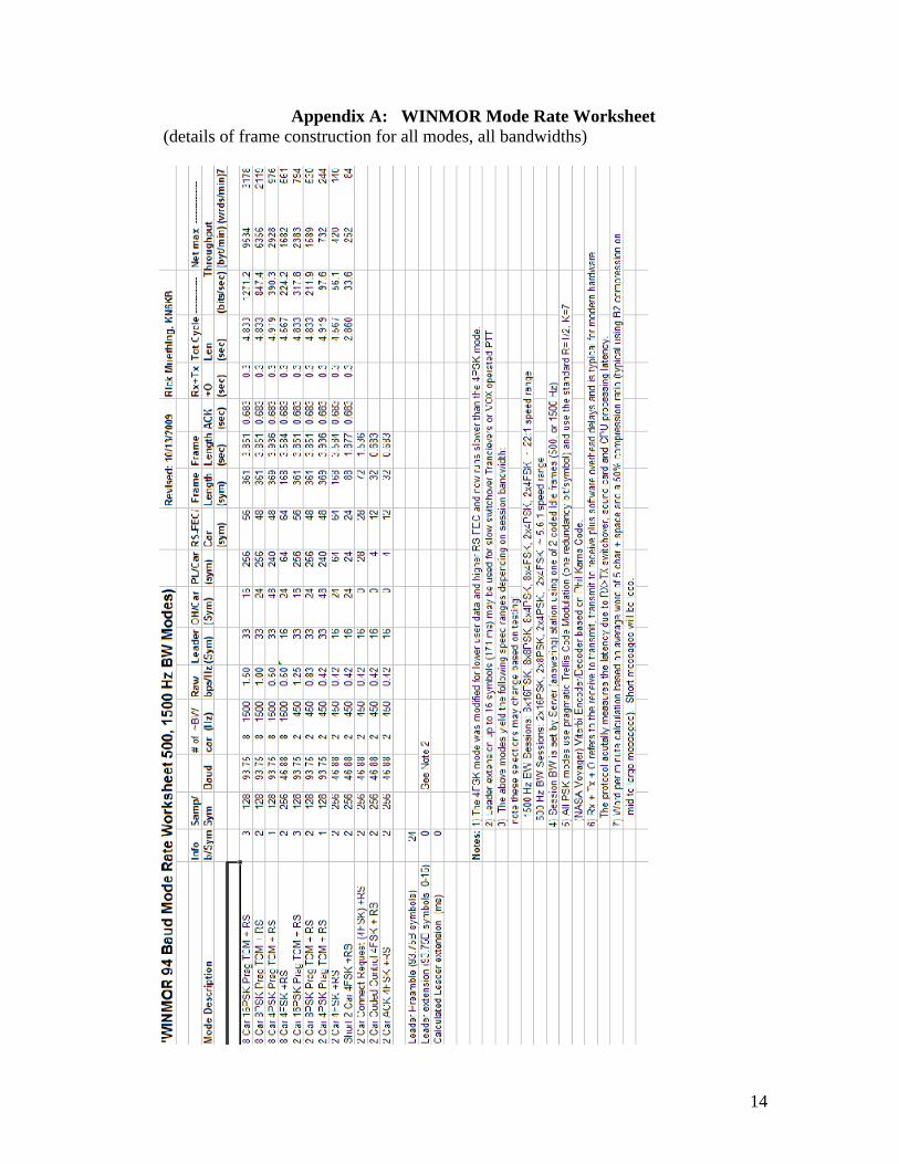
The following frame types MUST be supported. For Detailed frame parameters see the spread sheet in Appendix A.
6.2.1 Control frames: Fcrq Connect ReQuest frame: 2 Car 4FSK = type 0
Sent by the station initiating the connection (Client). Contains call signs of calling and target stations and 2 byte sumcheck. The session Bandwidth is set by the answering (Server) station.
Fcrq Encoding: Fcrq := Pilot & Sr & Bdata & Bsch & Bscl & BRS
Bdata := Calling call sign & Remote call sign. Callsigns are packed to 12 byte array of 6 bit characters and must be A-Z, 0-9 with an optional ssid of 0 15. Function FormatCallsToByte is used to pack the 12 byte array.
Bsch is the high byte of the CRC16 sum check of Bdata
Bscl is the low byte of the CRC16 sum check of Bdata
BRS is the 14 check parity bytes from a shortened RS (255,241 ) code correcting up to 7 bytes
Fcrq Total payload (2 carriers) of 28 bytes including CRC16 and RS correction check bytes and is always sent using 2 carrier 4FSK modulation (2 user bits per symbol)
FID ID frame: 2 Car 4FSK = type 15 Sent by the station to ID. Contains call sign of sending station and optional Grid 6
character Grid square.The ID frame is sent automatically at 10 minute intervals by the
7
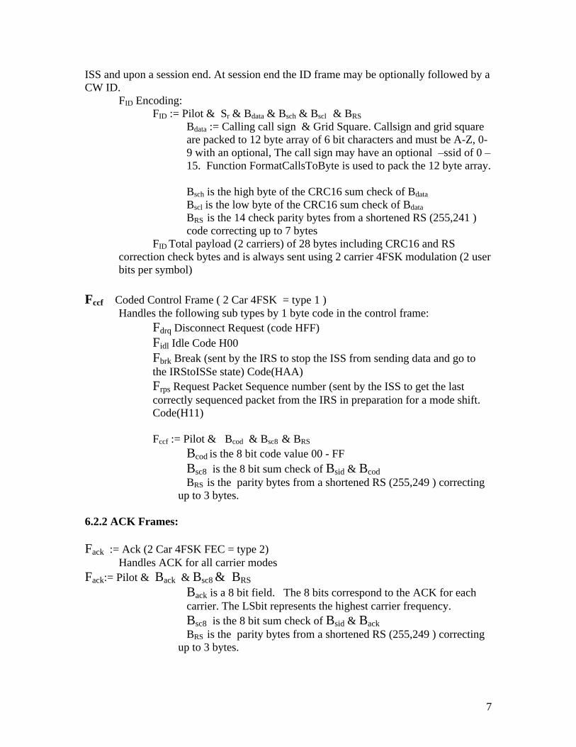
ISS and upon a session end. At session end the ID frame may be optionally followed by a CW ID.
FID Encoding: FID := Pilot & Sr & Bdata & Bsch & Bscl & BRS
Bdata := Calling call sign & Grid Square. Callsign and grid square are packed to 12 byte array of 6 bit characters and must be A-Z, 0-9 with an optional, The call sign may have an optional ssid of 0
15. Function FormatCallsToByte is used to pack the 12 byte array.
Bsch is the high byte of the CRC16 sum check of Bdata
Bscl is the low byte of the CRC16 sum check of Bdata
BRS is the 14 check parity bytes from a shortened RS (255,241 ) code correcting up to 7 bytes
FID Total payload (2 carriers) of 28 bytes including CRC16 and RS correction check bytes and is always sent using 2 carrier 4FSK modulation (2 user bits per symbol)
Fccf Coded Control Frame ( 2 Car 4FSK = type 1 ) Handles the following sub types by 1 byte code in the control frame:
Fdrq Disconnect Request (code HFF) Fidl Idle Code H00 Fbrk Break (sent by the IRS to stop the ISS from sending data and go to the IRStoISSe state) Code(HAA) Frps Request Packet Sequence number (sent by the ISS to get the last correctly sequenced packet from the IRS in preparation for a mode shift. Code(H11)
Fccf := Pilot & Bcod & Bsc8 & BRS
Bcod is the 8 bit code value 00 - FF Bsc8 is the 8 bit sum check of Bsid & Bcod BRS is the parity bytes from a shortened RS (255,249 ) correcting
up to 3 bytes.
6.2.2 ACK Frames:
Fack := Ack (2 Car 4FSK FEC = type 2) Handles ACK for all carrier modes
Fack:= Pilot & Back & Bsc8 & BRS
Back is a 8 bit field. The 8 bits correspond to the ACK for each carrier. The LSbit represents the highest carrier frequency. Bsc8 is the 8 bit sum check of Bsid & Back BRS is the parity bytes from a shortened RS (255,249 ) correcting
up to 3 bytes.
8
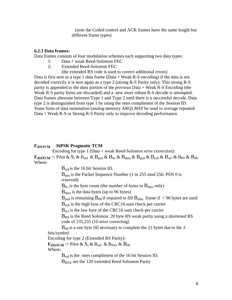
(note the Coded control and ACK frames have the same length but
different frame types)
6.2.3 Data frames: Data frames consists of four modulation schemes each supporting two data types:
1: Data + weak Reed-Solomon FEC 2: Extended Reed-Solomon FEC
(the extended RS code is used to correct additional errors) Data is first sent as a type 1 data frame (Data + Weak R-S encoding) if the data is not decoded correctly it is sent again as a type 2 (strong R-S Parity only). This strong R-S parity is appended to the data portion of the previous Data + Weak R-S Encoding (the Weak R-S parity bytes are discarded) and a new more robust R-S decode is attempted. Data frames alternate between Type 1 and Type 2 until there is a successful decode. Data type 2 is distinguished from type 1 by using the ones compliment of the Session ID. Some form of data summation (analog memory ARQ) MAY be used to average repeated Data + Weak R-S or Strong R-S Parity only to improve decoding performance.
Fd16TCM 16PSK Pragmatic TCM Encoding for type 1 (Data + weak Reed-Solomon error correction):
Fd16TCM := Pilot & Sr & Bsid & Bpsn & Bbc & Bdata & Bpad & Bsch & Bscl & BRS & B00 Where:
Bsid is the 16 bit Session ID. Bpsn is the Packet Sequence Number (1 to 255 mod 256. PSN 0 is reserved) Bbc is the byte count (the number of bytes in Bdata only) Bdata is the data bytes (up to 96 bytes) Bpad is remaining B00 if required to fill Bdata frame if < 96 bytes are used Bsch is the high byte of the CRC16 sum check per carrier Bscl is the low byte of the CRC16 sum check per carrier BRS is the Reed Solomon 20 byte RS weak parity using a shortened RS code of 235,255 (10 error correcting) B00 is a one byte fill necessary to complete the 21 bytes due to the 3
bits/symbol Encoding for type 2 (Extended RS Parity): Fd16TCM := Pilot & Sr & Bsid & BRSX & B00 Where:
Bsid is the ones compliment of the 16 bit Session ID. BRSX are the 120 extended Reed Solomon Parity
9
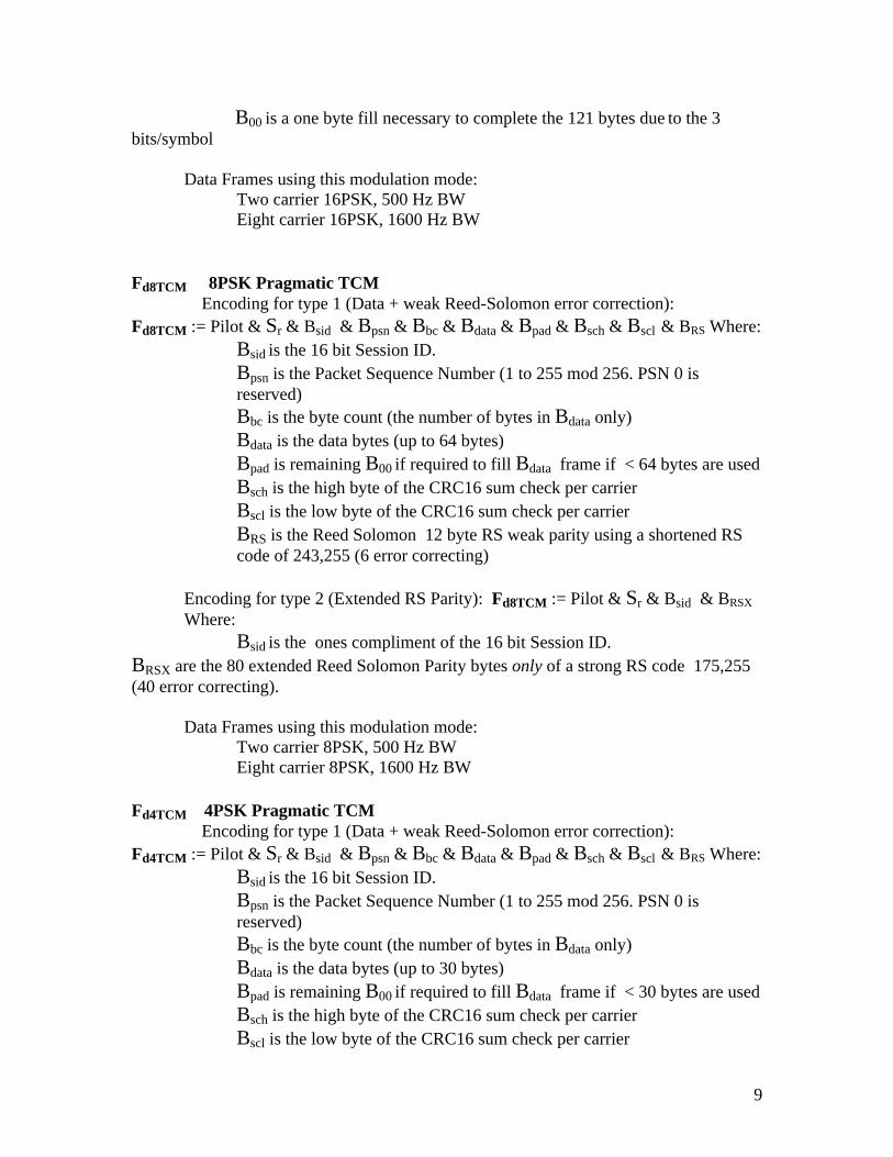
B00 is a one byte fill necessary to complete the 121 bytes due to the 3
bits/symbol
Data Frames using this modulation mode: Two carrier 16PSK, 500 Hz BW Eight carrier 16PSK, 1600 Hz BW
Fd8TCM 8PSK Pragmatic TCM Encoding for type 1 (Data + weak Reed-Solomon error correction):
Fd8TCM := Pilot & Sr & Bsid & Bpsn & Bbc & Bdata & Bpad & Bsch & Bscl & BRS Where: Bsid is the 16 bit Session ID. Bpsn is the Packet Sequence Number (1 to 255 mod 256. PSN 0 is reserved) Bbc is the byte count (the number of bytes in Bdata only) Bdata is the data bytes (up to 64 bytes) Bpad is remaining B00 if required to fill Bdata frame if < 64 bytes are used Bsch is the high byte of the CRC16 sum check per carrier Bscl is the low byte of the CRC16 sum check per carrier BRS is the Reed Solomon 12 byte RS weak parity using a shortened RS code of 243,255 (6 error correcting)
Encoding for type 2 (Extended RS Parity): Fd8TCM := Pilot & Sr & Bsid & BRSX Where:
Bsid is the ones compliment of the 16 bit Session ID. BRSX are the 80 extended Reed Solomon Parity bytes only of a strong RS code 175,255 (40 error correcting).
Fd4TCM 4PSK Pragmatic TCM Encoding for type 1 (Data + weak Reed-Solomon error correction):
Fd4TCM := Pilot & Sr & Bsid & Bpsn & Bbc & Bdata & Bpad & Bsch & Bscl & BRS Where: Bsid is the 16 bit Session ID. Bpsn is the Packet Sequence Number (1 to 255 mod 256. PSN 0 is reserved) Bbc is the byte count (the number of bytes in Bdata only) Bdata is the data bytes (up to 30 bytes) Bpad is remaining B00 if required to fill Bdata frame if < 30 bytes are used Bsch is the high byte of the CRC16 sum check per carrier Bscl is the low byte of the CRC16 sum check per carrier
10
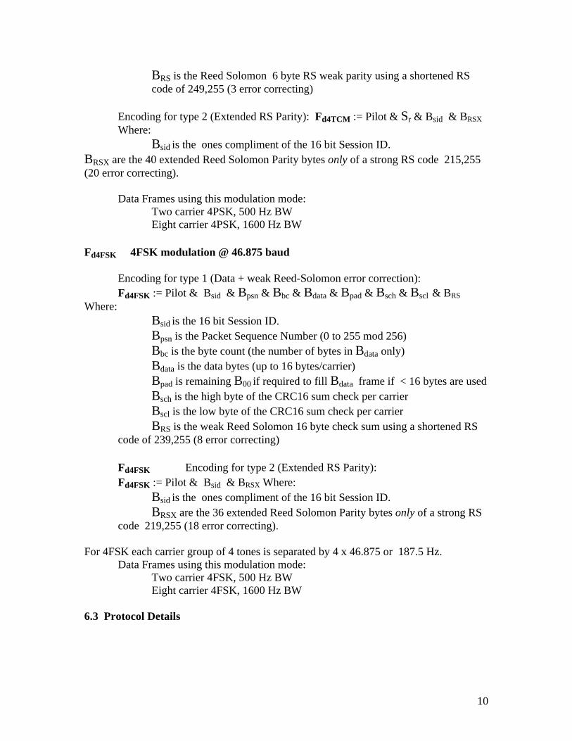
BRS is the Reed Solomon 6 byte RS weak parity using a shortened RS code of 249,255 (3 error correcting)
Encoding for type 2 (Extended RS Parity): Fd4TCM := Pilot & Sr & Bsid & BRSX Where:
Bsid is the ones compliment of the 16 bit Session ID. BRSX are the 40 extended Reed Solomon Parity bytes only of a strong RS code 215,255 (20 error correcting).
Encoding for type 1 (Data + weak Reed-Solomon error correction): Fd4FSK := Pilot & Bsid & Bpsn & Bbc & Bdata & Bpad & Bsch & Bscl & BRS
Where: Bsid is the 16 bit Session ID. Bpsn is the Packet Sequence Number (0 to 255 mod 256) Bbc is the byte count (the number of bytes in Bdata only) Bdata is the data bytes (up to 16 bytes/carrier) Bpad is remaining B00 if required to fill Bdata frame if < 16 bytes are used Bsch is the high byte of the CRC16 sum check per carrier Bscl is the low byte of the CRC16 sum check per carrier BRS is the weak Reed Solomon 16 byte check sum using a shortened RS
code of 239,255 (8 error correcting)
Fd4FSK Encoding for type 2 (Extended RS Parity): Fd4FSK := Pilot & Bsid & BRSX Where:
Bsid is the ones compliment of the 16 bit Session ID. BRSX are the 36 extended Reed Solomon Parity bytes only of a strong RS
code 219,255 (18 error correcting).
For 4FSK each carrier group of 4 tones is separated by 4 x 46.875 or 187.5 Hz. Data Frames using this modulation mode:
6.3.1 Protocol Rules: (refer to state diagram Fig 6-1) 1) Offline.
a. When WINMOR is in the Offline State it may send no data, receive no data and the sound card is deactivated and sound card resources released.
2) All other states, events, actions and state sequencing details are shown in the Protocol rules of Appendix C.
7.0 Example Forwarding Scenarios:
7.1 A typical Forwarding Session: (no errors or repeats)
CLIENT SERVER State Frame Sent State Frame Sent CONNECTING CONREQ
DISCONNECTED ACK (BW) ISS IDLE
IRS BREAK ISS ACK
IRStoISS DATA
IRSISS
Disconnected
IRStoISS
Disconnecting
OfflineSound card
Disabled
Connecting
Repeat ConnectRequest
DisconnectREQReceived
ACK(BW)Received
Repeat BREAK
ACK received
Answer with ACK,Disconnect REQOr BREAK
Timeout
BREAK receivedSend ACK
IDLE received withOutbound pendingOr BREAK
Send DATA,IDLE or OVERProcess ACK Reply
Accepted Connect REQSend ACK(BW)
SendDisconnect REQ
(repeat up to 4x)
AnyState
ACK Receivedor 4 repeats
Disconnect REQ Received, Send ACK
AnyState
WINMOR Protocol States
Initiate Connection
Timeout
ISS, ISS ModeShift,IRS, IRS ModeShift,and IRStoISS states
ISS ModeShift
PSNRcvd
Send ReqLast Sequenced
PSN
Updated Dec 10, 2009
IRS ModeShift
Req Last PSNData Rcvd
ConnectPending
Connect FrameDetected
Rejected
Send BREAK
IRS StatesISS StatesTransition StatesUnconnected States
Send ID
ID Sent
12
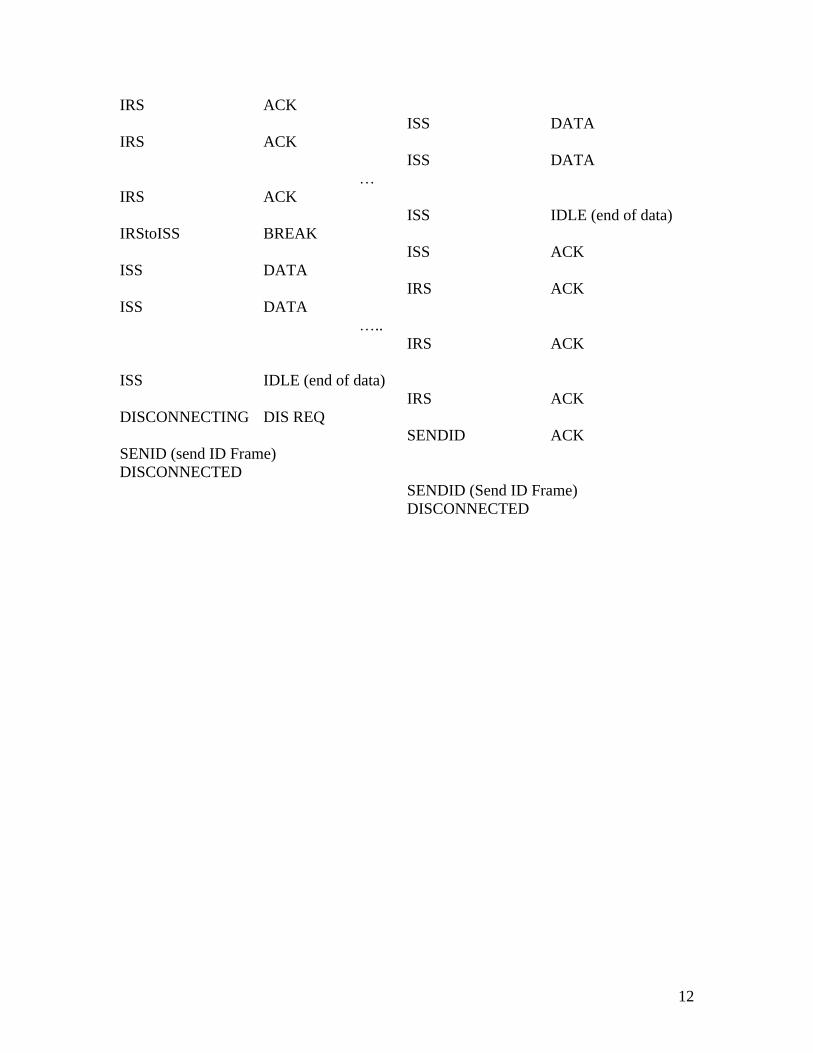
IRS ACK
ISS DATA IRS ACK
ISS DATA
IRS ACK
ISS IDLE (end of data) IRStoISS BREAK
ISS ACK ISS DATA
IRS ACK ISS DATA
.. IRS ACK
ISS IDLE (end of data) IRS ACK
DISCONNECTING DIS REQ SENDID ACK
SENID (send ID Frame) DISCONNECTED
SENDID (Send ID Frame) DISCONNECTED
13
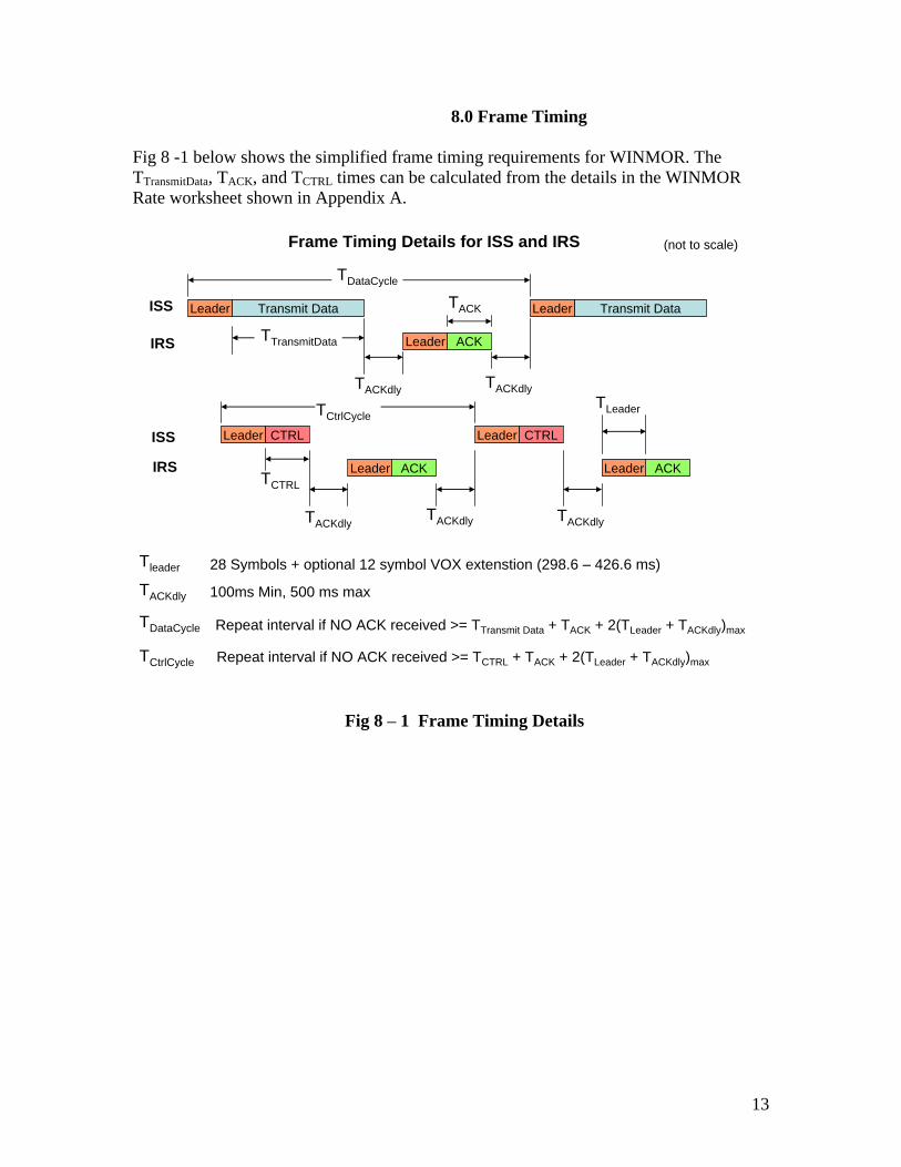
8.0 Frame Timing
Fig 8 -1 below shows the simplified frame timing requirements for WINMOR. The TTransmitData, TACK, and TCTRL times can be calculated from the details in the WINMOR Rate worksheet shown in Appendix A.
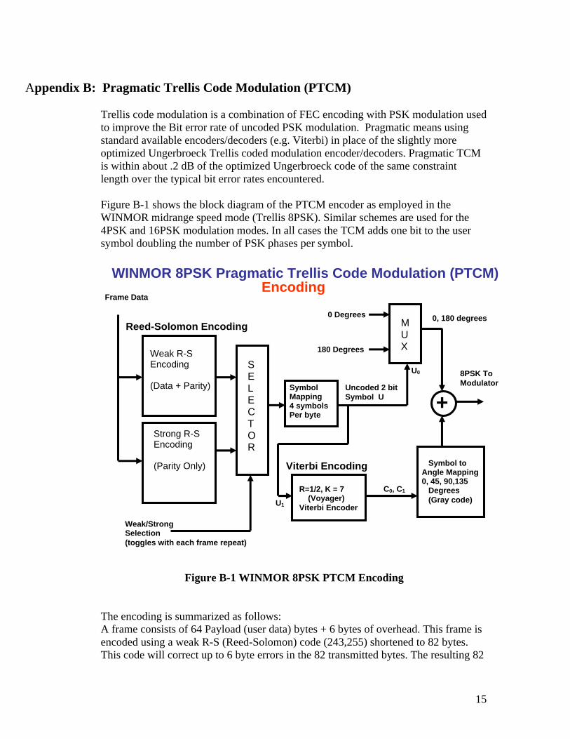
Trellis code modulation is a combination of FEC encoding with PSK modulation used to improve the Bit error rate of uncoded PSK modulation. Pragmatic means using standard available encoders/decoders (e.g. Viterbi) in place of the slightly more optimized Ungerbroeck Trellis coded modulation encoder/decoders. Pragmatic TCM is within about .2 dB of the optimized Ungerbroeck code of the same constraint length over the typical bit error rates encountered.
Figure B-1 shows the block diagram of the PTCM encoder as employed in the WINMOR midrange speed mode (Trellis 8PSK). Similar schemes are used for the 4PSK and 16PSK modulation modes. In all cases the TCM adds one bit to the user symbol doubling the number of PSK phases per symbol.
Figure B-1 WINMOR 8PSK PTCM Encoding
The encoding is summarized as follows: A frame consists of 64 Payload (user data) bytes + 6 bytes of overhead. This frame is encoded using a weak R-S (Reed-Solomon) code (243,255) shortened to 82 bytes. This code will correct up to 6 byte errors in the 82 transmitted bytes. The resulting 82
bytes are mapped into 328 symbols of 2 bits each. The most significant symbol Bit U0
is not FEC coded and selects an angle of 0 degrees (U0 = 0) or 180 degrees (U0 = 1) The least significant bit U1 is fed into a standard (NASA Voyager) R= ½ , K=7 Viterbi Encoder which produces 2 FEC coded output bits C0 and C1 for each input bit U1.
C0 and C1 are mapped to one of 4 phase values 0, 45, 90 or 135 using a gray code mapping. This phase value is added to the output of the multiplexer (0 or 180 degrees) to obtain the final 8PSK modulation angle (0 to 315 degrees in 45 degree steps)
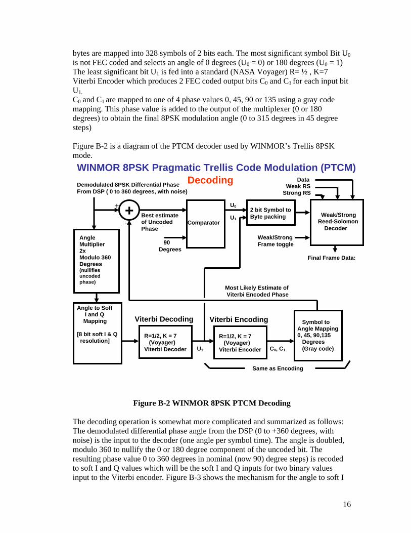
Figure B-2 is a diagram of the PTCM decoder used by WINMOR s Trellis 8PSK mode.
Figure B-2 WINMOR 8PSK PTCM Decoding
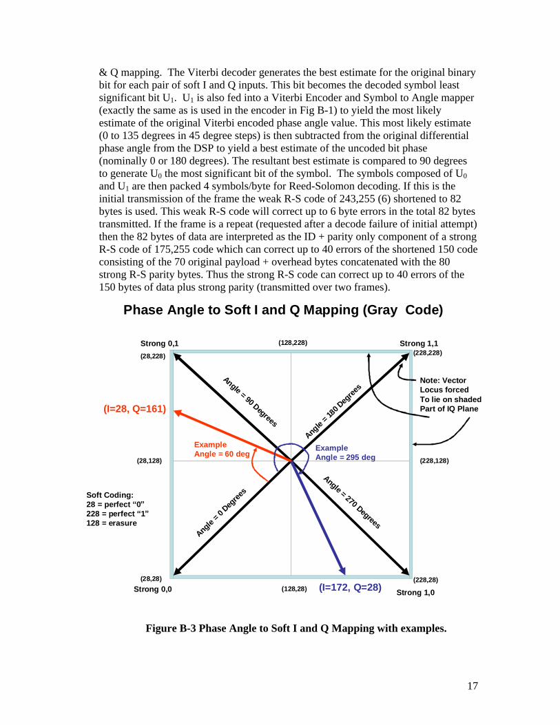
The decoding operation is somewhat more complicated and summarized as follows: The demodulated differential phase angle from the DSP (0 to +360 degrees, with noise) is the input to the decoder (one angle per symbol time). The angle is doubled, modulo 360 to nullify the 0 or 180 degree component of the uncoded bit. The resulting phase value 0 to 360 degrees in nominal (now 90) degree steps) is recoded to soft I and Q values which will be the soft I and Q inputs for two binary values input to the Viterbi encoder. Figure B-3 shows the mechanism for the angle to soft I
& Q mapping. The Viterbi decoder generates the best estimate for the original binary bit for each pair of soft I and Q inputs. This bit becomes the decoded symbol least significant bit U1. U1 is also fed into a Viterbi Encoder and Symbol to Angle mapper (exactly the same as is used in the encoder in Fig B-1) to yield the most likely estimate of the original Viterbi encoded phase angle value. This most likely estimate (0 to 135 degrees in 45 degree steps) is then subtracted from the original differential phase angle from the DSP to yield a best estimate of the uncoded bit phase (nominally 0 or 180 degrees). The resultant best estimate is compared to 90 degrees to generate U0 the most significant bit of the symbol. The symbols composed of U0
and U1 are then packed 4 symbols/byte for Reed-Solomon decoding. If this is the initial transmission of the frame the weak R-S code of 243,255 (6) shortened to 82 bytes is used. This weak R-S code will correct up to 6 byte errors in the total 82 bytes transmitted. If the frame is a repeat (requested after a decode failure of initial attempt) then the 82 bytes of data are interpreted as the ID + parity only component of a strong R-S code of 175,255 code which can correct up to 40 errors of the shortened 150 code consisting of the 70 original payload + overhead bytes concatenated with the 80 strong R-S parity bytes. Thus the strong R-S code can correct up to 40 errors of the 150 bytes of data plus strong parity (transmitted over two frames).
Figure B-3 Phase Angle to Soft I and Q Mapping with examples.
Strong 1,1Strong 0,1
Strong 0,0 Strong 1,0
(228,228)
(228,28)(28,28)
(28,228)
(28,128)
(128,28)
(228,128)
(128,228)
Angle = 0
Degre
es
Angle = 18
0 Deg
rees
Angle = 90 Degrees
Angle = 270 Degrees
ExampleAngle = 60 deg
(I=28, Q=161)
Phase Angle to Soft I and Q Mapping (Gray Code)
Note: VectorLocus forcedTo lie on shadedPart of IQ Plane
A similar approach to PTCM encoding and decoding is done on both the 4PSK mode (no uncoded bits, 2 Viterbi bits) and the 16PSK mode (2 uncoded bits, 2 Viterbi bits).
References:
1) A Pragmatic Approach to Trellis-Coded Modulation. A. Viterbi, J. Wolf, E. Zejavo, R. Padovani IEEE Communications Magazine July 1989, pp11-19 http://ieeexplore.ieee.org/xpl/freeabs_all.jsp?arnumber=31452
2) Data Recovery in Differentially Encoded Quadrature Phase Shift Keying. J. Bard, M. Nezami, and M. Diaz Mnemonics, Inc Melbourne, FL. http://whitepapers.silicon.com/0,39024759,60446221p,00.htm
3) Error Control Coding, Second Edition. Shu Lin and Daniel Costello Pearson Prentice Hall 2004 ISBN 0-13-042672-5
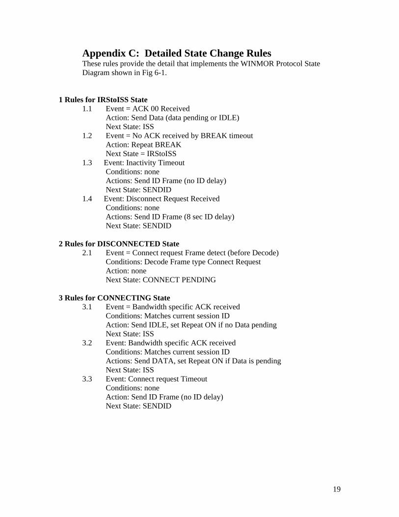
Appendix C: Detailed State Change Rules These rules provide the detail that implements the WINMOR Protocol State Diagram shown in Fig 6-1.
1 Rules for IRStoISS State 1.1 Event = ACK 00 Received
Action: Send Data (data pending or IDLE) Next State: ISS
1.2 Event = No ACK received by BREAK timeout Action: Repeat BREAK Next State = IRStoISS
1.3 Event: Inactivity Timeout Conditions: none Actions: Send ID Frame (no ID delay) Next State: SENDID
1.4 Event: Disconnect Request Received Conditions: none Actions: Send ID Frame (8 sec ID delay) Next State: SENDID
2 Rules for DISCONNECTED State 2.1 Event = Connect request Frame detect (before Decode)
Conditions: Decode Frame type Connect Request Action: none Next State: CONNECT PENDING
3 Rules for CONNECTING State 3.1 Event = Bandwidth specific ACK received
Conditions: Matches current session ID Action: Send IDLE, set Repeat ON if no Data pending Next State: ISS
3.2 Event: Bandwidth specific ACK received Conditions: Matches current session ID Actions: Send DATA, set Repeat ON if Data is pending Next State: ISS
3.3 Event: Connect request Timeout Conditions: none Action: Send ID Frame (no ID delay) Next State: SENDID
20
4 Rules for CONNECT PENDING State
4.1 Event = Successful Decode to Target Call sign Conditions: Target Call sign matches local call sign Action: Send bandwidth specific ACK, set Repeat OFF Next State: IRS
4.2 Event: Decode Failure Conditions: Sumcheck fail or Target <> Local call sign Actions: none Next State: DISCONNECTED
5 Rules for DISCONNECTING State 5.1 Event = Control Frame Timeout
Conditions: Disconnect Repeat count < 5 Action: Send Disconnect Request, set Repeat ON Next State: DISCONNECTING
5.2 Event: Control Frame Timeout Conditions: Disconnect Repeat count > = 5 Actions: Send ID Frame (no ID delay) Next State: SENDID
6 Rules for IRS State 6.1 Event = Data Received, Good match to ID bits
Conditions: Session ID match on at least one carrier Action: Send ACK for each carrier correct, no repeats Next State: IRS
6.2 Event: Data Received, Poor match to ID Conditions: Session ID mismatch on all carriers Actions: none Next State: IRS
6.3 Event: Control Received, Request Last PSN Conditions: Session ID match, Sumcheck OK Actions: Send ACK containing Last PSN Next State: IRS MODESHIFT
6.4 Event: Inactivity Timeout Conditions: none Actions: Send ID Frame (no ID delay) Next State: SENDID
6.5 Event: Connect Request Frame Received Conditions: Session ID Match, Sumcheck OK Action: Send Bandwidth specific ACK Next State: IRS
6.6 Event: Disconnect Request Received Conditions: none Actions: Send ID Frame (8 sec ID delay) Next State: SENDID
21
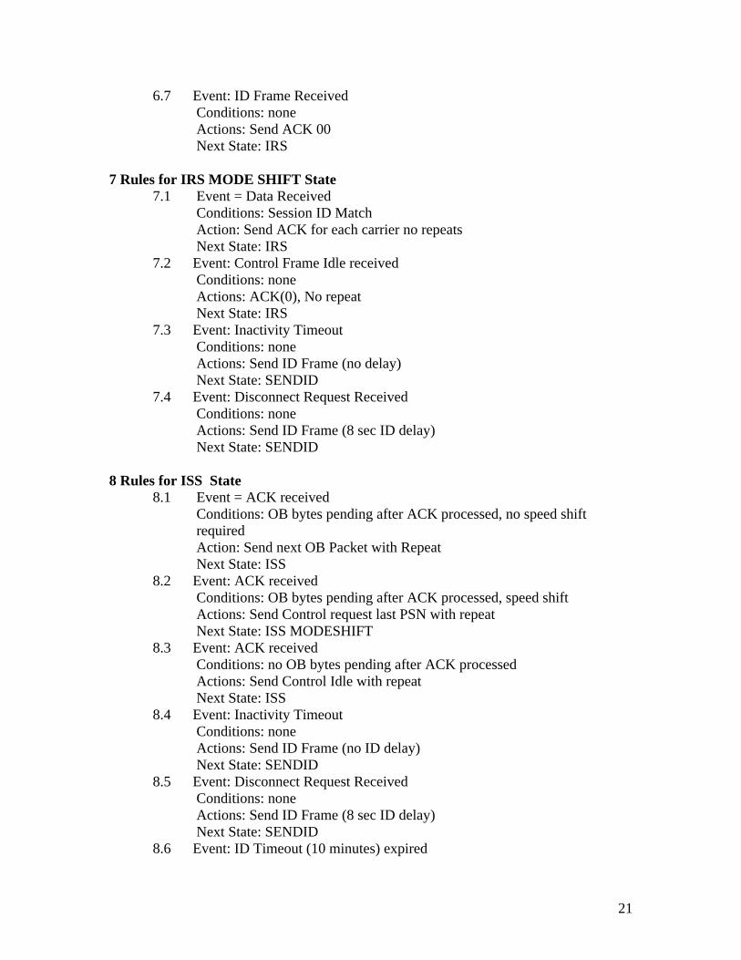
6.7 Event: ID Frame Received
Conditions: none Actions: Send ACK 00 Next State: IRS
7 Rules for IRS MODE SHIFT State 7.1 Event = Data Received
Conditions: Session ID Match Action: Send ACK for each carrier no repeats Next State: IRS
7.2 Event: Control Frame Idle received Conditions: none Actions: ACK(0), No repeat Next State: IRS
7.3 Event: Inactivity Timeout Conditions: none Actions: Send ID Frame (no delay) Next State: SENDID
7.4 Event: Disconnect Request Received Conditions: none Actions: Send ID Frame (8 sec ID delay) Next State: SENDID
8 Rules for ISS State 8.1 Event = ACK received
Conditions: OB bytes pending after ACK processed, no speed shift required Action: Send next OB Packet with Repeat Next State: ISS
8.2 Event: ACK received Conditions: OB bytes pending after ACK processed, speed shift Actions: Send Control request last PSN with repeat Next State: ISS MODESHIFT
8.3 Event: ACK received Conditions: no OB bytes pending after ACK processed Actions: Send Control Idle with repeat Next State: ISS
8.4 Event: Inactivity Timeout Conditions: none Actions: Send ID Frame (no ID delay) Next State: SENDID
8.5 Event: Disconnect Request Received Conditions: none Actions: Send ID Frame (8 sec ID delay) Next State: SENDID
8.6 Event: ID Timeout (10 minutes) expired
22
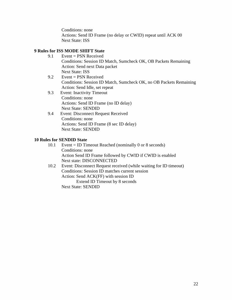
Conditions: none Actions: Send ID Frame (no delay or CWID) repeat until ACK 00 Next State: ISS
9 Rules for ISS MODE SHIFT State 9.1 Event = PSN Received
Conditions: Session ID Match, Sumcheck OK, OB Packets Remaining Action: Send next Data packet Next State: ISS
9.2 Event = PSN Received Conditions: Session ID Match, Sumcheck OK, no OB Packets Remaining Action: Send Idle, set repeat
9.3 Event: Inactivity Timeout Conditions: none Actions: Send ID Frame (no ID delay) Next State: SENDID
9.4 Event: Disconnect Request Received Conditions: none Actions: Send ID Frame (8 sec ID delay) Next State: SENDID
10 Rules for SENDID State 10.1 Event = ID Timeout Reached (nominally 0 or 8 seconds)
Conditions: none Action Send ID Frame followed by CWID if CWID is enabled Next state: DISCONNECTED
10.2 Event: Disconnect Request received (while waiting for ID timeout) Conditions: Session ID matches current session Action: Send ACK(FF) with session ID