1 WINSAFE Corp. OPERATING INSTRUCTIONS MODULAR BEAMS and ACCESSORIES THESE INSTRUCTIONS MUST BE READ AND UNDERSTOOD BY ANYONE INSTALLING OR SUSPENDING EQUIPMENT FROM WINSAFE MODULAR BEAMS AND ACCESSORIES. ANY QUESTIONS MUST BE DIRECTED TO THE WINSAFE DEALER OR DIRECTLY TO THE ADDRESS BELOW. Winsafe Corp. One Valleywood Drive, #1 Markham, Ontario – L3R 5L9 Tel: 905-474-9340 Fax: 905-474-9341 Email: [email protected]www.winsafe.com
Transcript
1
WINSAFE Corp.OPERATING INSTRUCTIONS
MODULAR BEAMS and ACCESSORIES
THESE INSTRUCTIONS MUST BE READ AND UNDERSTOOD BY ANYONE
INSTALLING OR SUSPENDING EQUIPMENT FROM WINSAFE MODULAR BEAMS
AND ACCESSORIES. ANY QUESTIONS MUST BE DIRECTED TO THE WINSAFE
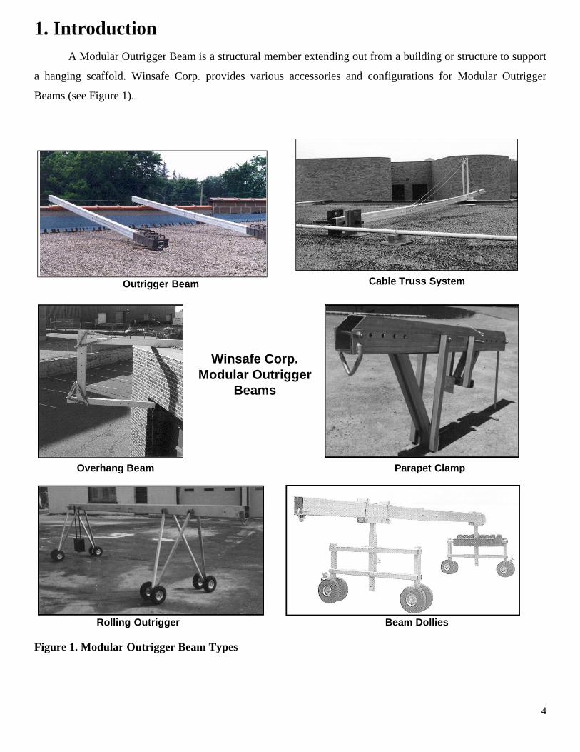
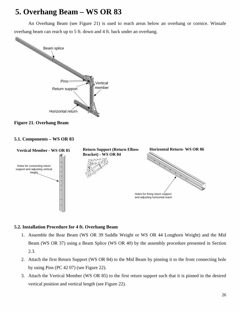
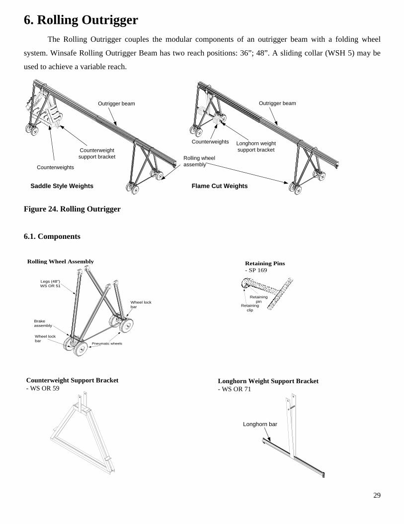
1. Introduction A Modular Outrigger Beam is a structural member extending out from a building or structure to support
a hanging scaffold. Winsafe Corp. provides various accessories and configurations for Modular Outrigger
Beams (see Figure 1).
Outrigger Beam Cable Truss System
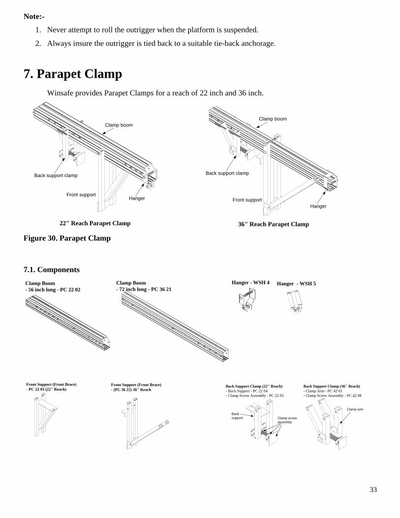
Overhang Beam Parapet Clamp
Winsafe Corp.Modular Outrigger
Beams
Beam DolliesRolling Outrigger
Figure 1. Modular Outrigger Beam Types
5
2. Outrigger BeamOutrigger beams may be used individually or in pairs to support a hanging scaffold. Winsafe provides
two-section and three section outrigger beams for overhangs up to 48 inches.
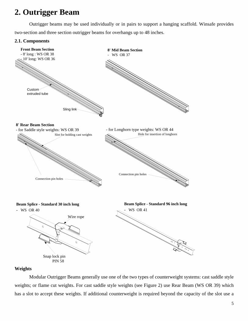
2.1. Components
8' Mid Beam Section- WS OR 37
Front Beam Section- 8' long : WS OR 38- 10' long: WS OR 36
Customextruded tube
Sling link
Slot for holding cast weights
Connection pin holes
8' Rear Beam Section- for Saddle style weights: WS OR 39 - for Longhorn type weights: WS OR 44
Hole for insertion of longhorn
Connection pin holes
Beam Splice - Standard 30 inch long
- WS OR 40
Wire rope`
Snap lock pin
Beam Splice - Standard 96 inch long
- WS OR 41
PIN 58
Weights
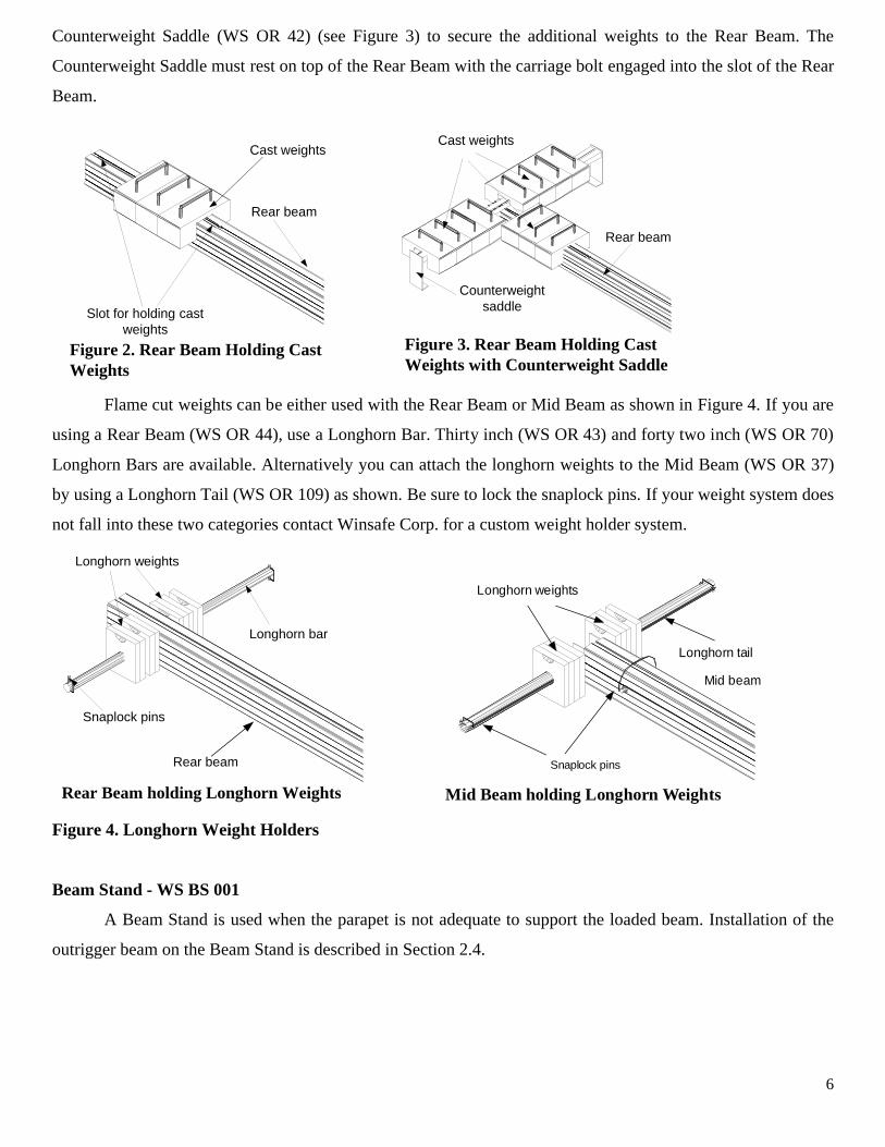
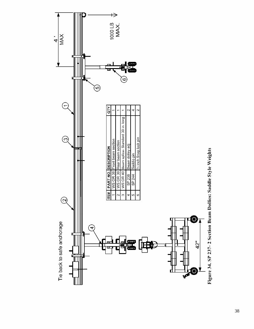
Modular Outrigger Beams generally use one of the two types of counterweight systems: cast saddle style
weights; or flame cut weights. For cast saddle style weights (see Figure 2) use Rear Beam (WS OR 39) which
has a slot to accept these weights. If additional counterweight is required beyond the capacity of the slot use a
6
Counterweight Saddle (WS OR 42) (see Figure 3) to secure the additional weights to the Rear Beam. The
Counterweight Saddle must rest on top of the Rear Beam with the carriage bolt engaged into the slot of the Rear
Beam.
Cast weights
Rear beam
Slot for holding castweights
Cast weights
Figure 2. Rear Beam Holding CastWeights
Figure 3. Rear Beam Holding CastWeights with Counterweight Saddle
Counterweightsaddle
Rear beam
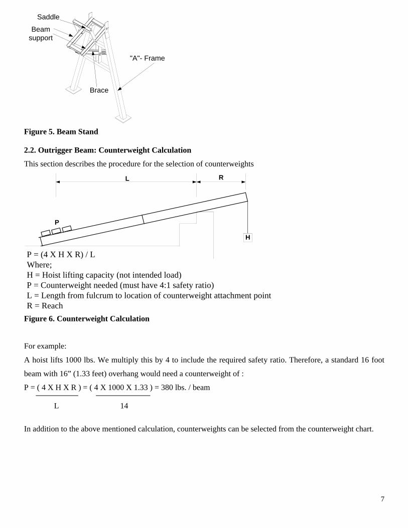
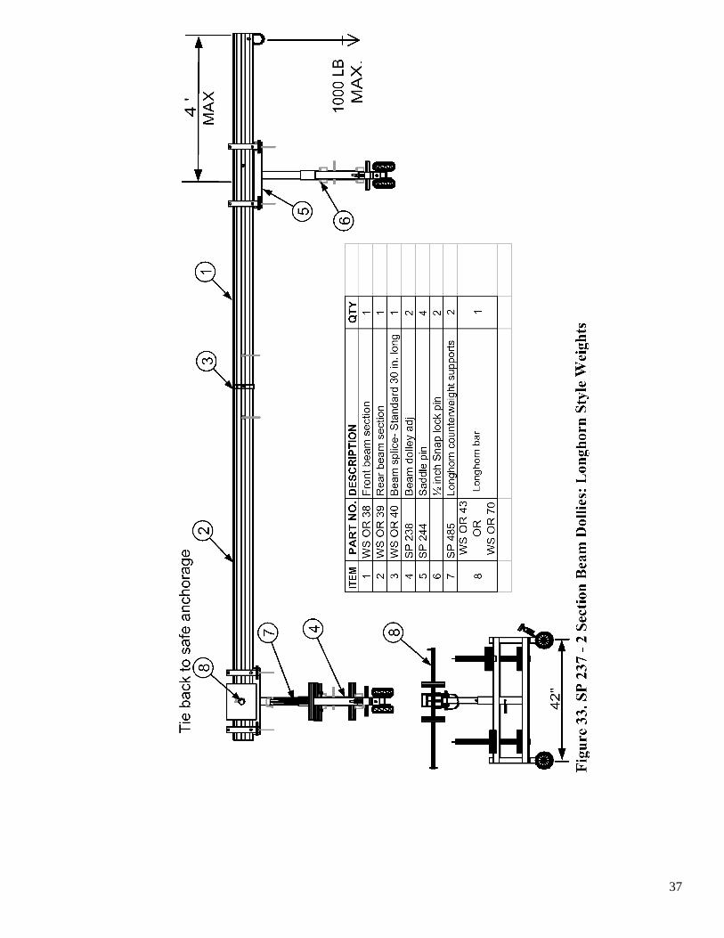
Flame cut weights can be either used with the Rear Beam or Mid Beam as shown in Figure 4. If you are
using a Rear Beam (WS OR 44), use a Longhorn Bar. Thirty inch (WS OR 43) and forty two inch (WS OR 70)
Longhorn Bars are available. Alternatively you can attach the longhorn weights to the Mid Beam (WS OR 37)
by using a Longhorn Tail (WS OR 109) as shown. Be sure to lock the snaplock pins. If your weight system does
not fall into these two categories contact Winsafe Corp. for a custom weight holder system.
Longhorn weights
Longhorn bar
Snaplock pins
Rear beam
Rear Beam holding Longhorn Weights
Snaplock pins
Longhorn weights
Longhorn tail
Mid beam
Mid Beam holding Longhorn Weights
Figure 4. Longhorn Weight Holders
Beam Stand - WS BS 001
A Beam Stand is used when the parapet is not adequate to support the loaded beam. Installation of the
outrigger beam on the Beam Stand is described in Section 2.4.
7
Saddle
Beamsupport
Brace
"A"- Frame
Figure 5. Beam Stand
2.2. Outrigger Beam: Counterweight Calculation
This section describes the procedure for the selection of counterweights
P = (4 X H X R) / LWhere;H = Hoist lifting capacity (not intended load)P = Counterweight needed (must have 4:1 safety ratio)L = Length from fulcrum to location of counterweight attachment pointR = Reach
H
L R
P
Figure 6. Counterweight Calculation
For example:
A hoist lifts 1000 lbs. We multiply this by 4 to include the required safety ratio. Therefore, a standard 16 foot
beam with 16” (1.33 feet) overhang would need a counterweight of :
P = ( 4 X H X R ) = ( 4 X 1000 X 1.33 ) = 380 lbs. / beam L 14
In addition to the above mentioned calculation, counterweights can be selected from the counterweight chart.
8
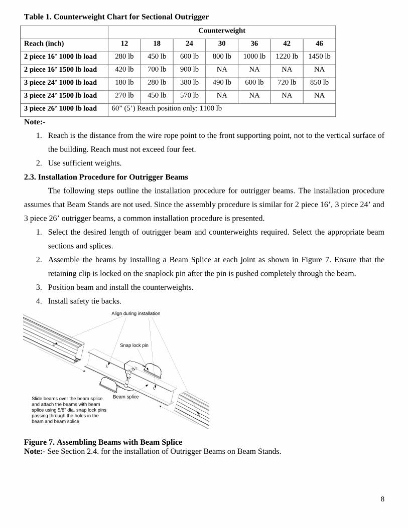
Table 1. Counterweight Chart for Sectional Outrigger
1. Reach is the distance from the wire rope point to the front supporting point, not to the vertical surface of
the building. Reach must not exceed four feet.
2. Use sufficient weights.
2.3. Installation Procedure for Outrigger Beams
The following steps outline the installation procedure for outrigger beams. The installation procedure
assumes that Beam Stands are not used. Since the assembly procedure is similar for 2 piece 16’, 3 piece 24’ and
3 piece 26’ outrigger beams, a common installation procedure is presented.
1. Select the desired length of outrigger beam and counterweights required. Select the appropriate beam
sections and splices.
2. Assemble the beams by installing a Beam Splice at each joint as shown in Figure 7. Ensure that the
retaining clip is locked on the snaplock pin after the pin is pushed completely through the beam.
3. Position beam and install the counterweights.
4. Install safety tie backs.
Align during installation
Beam spliceSlide beams over the beam spliceand attach the beams with beamsplice using 5/8" dia. snap lock pinspassing through the holes in thebeam and beam splice
Snap lock pin
Figure 7. Assembling Beams with Beam SpliceNote:- See Section 2.4. for the installation of Outrigger Beams on Beam Stands.
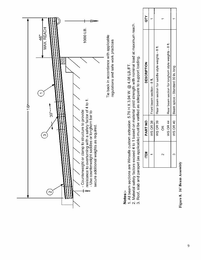
9
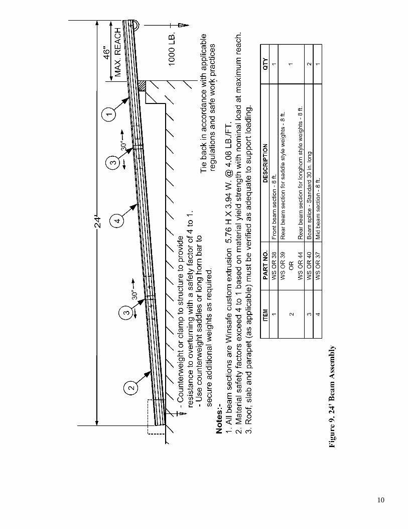
10
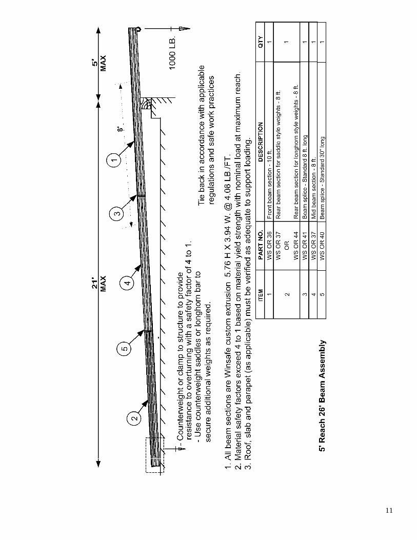
11
12
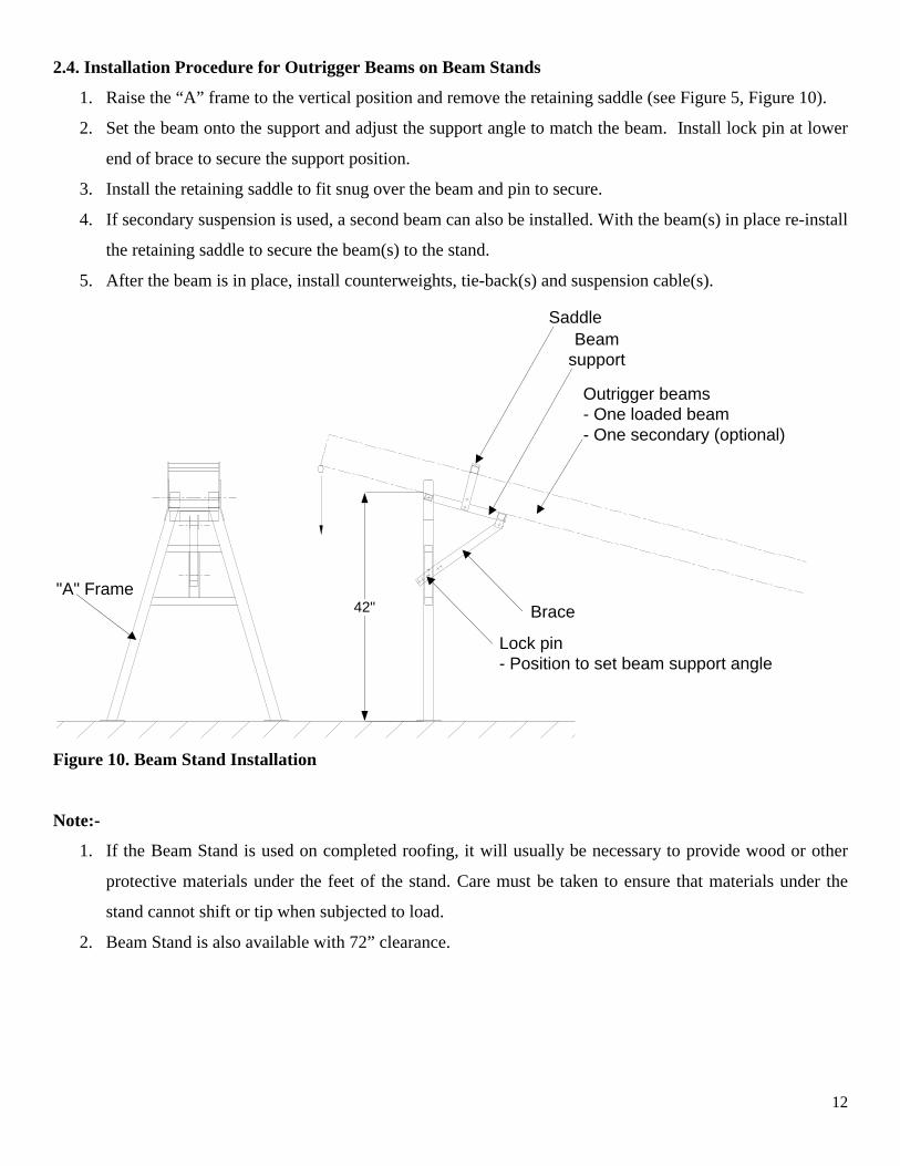
2.4. Installation Procedure for Outrigger Beams on Beam Stands
1. Raise the “A” frame to the vertical position and remove the retaining saddle (see Figure 5, Figure 10).
2. Set the beam onto the support and adjust the support angle to match the beam. Install lock pin at lower
end of brace to secure the support position.
3. Install the retaining saddle to fit snug over the beam and pin to secure.
4. If secondary suspension is used, a second beam can also be installed. With the beam(s) in place re-install
the retaining saddle to secure the beam(s) to the stand.
5. After the beam is in place, install counterweights, tie-back(s) and suspension cable(s).
"A" Frame
SaddleBeam
support
Outrigger beams- One loaded beam- One secondary (optional)
Brace
Lock pin- Position to set beam support angle
42"
Figure 10. Beam Stand Installation
Note:-
1. If the Beam Stand is used on completed roofing, it will usually be necessary to provide wood or other
protective materials under the feet of the stand. Care must be taken to ensure that materials under the
stand cannot shift or tip when subjected to load.
2. Beam Stand is also available with 72” clearance.
13
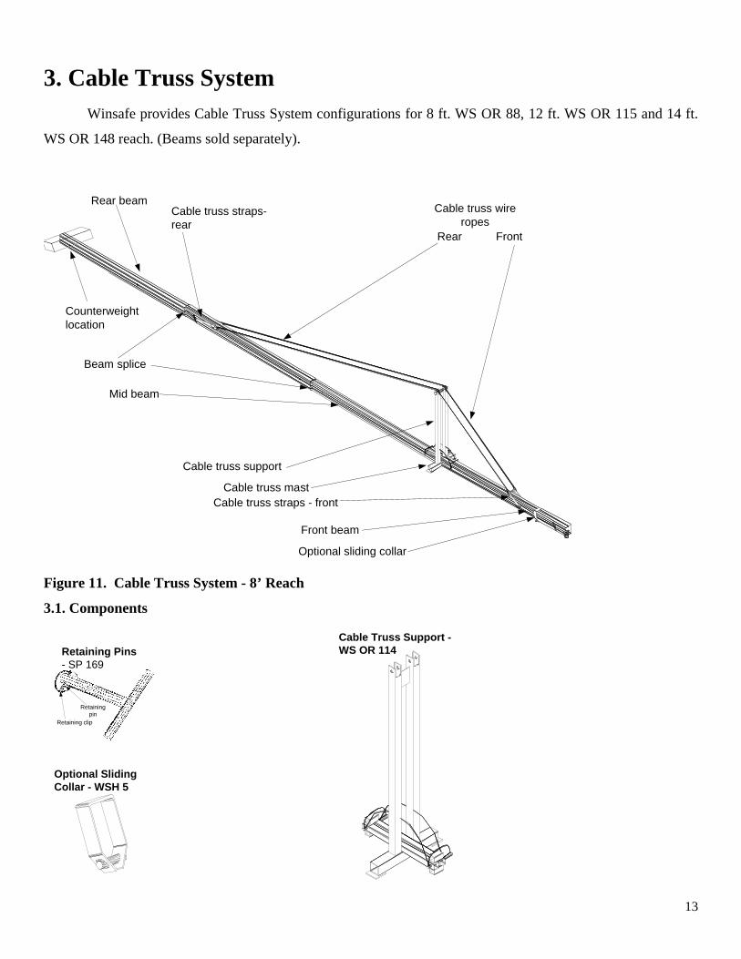
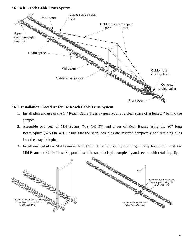
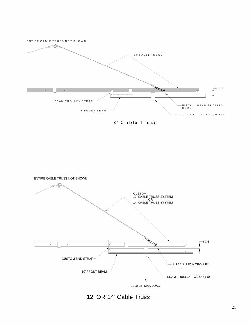
3. Cable Truss System Winsafe provides Cable Truss System configurations for 8 ft. WS OR 88, 12 ft. WS OR 115 and 14 ft.
WS OR 148 reach. (Beams sold separately).
Rear beamCable truss straps-rear
Cable truss wireropes
Rear Front
Beam splice
Mid beam
Cable truss support
Cable truss mastCable truss straps - front
Front beam
Optional sliding collar
Counterweightlocation
Figure 11. Cable Truss System - 8’ Reach
3.1. Components
Retaining Pins- SP 169
Retaining clip
Retainingpin
Optional SlidingCollar - WSH 5
Cable Truss Support -WS OR 114
14
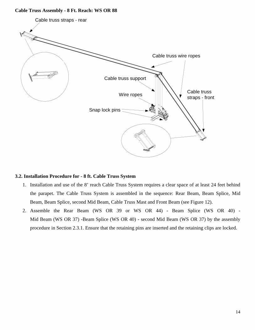
Cable Truss Assembly - 8 Ft. Reach: WS OR 88
Cable truss straps - rear
Cable trussstraps - front
Cable truss wire ropes
Cable truss support
Snap lock pins
Wire ropes
3.2. Installation Procedure for - 8 ft. Cable Truss System
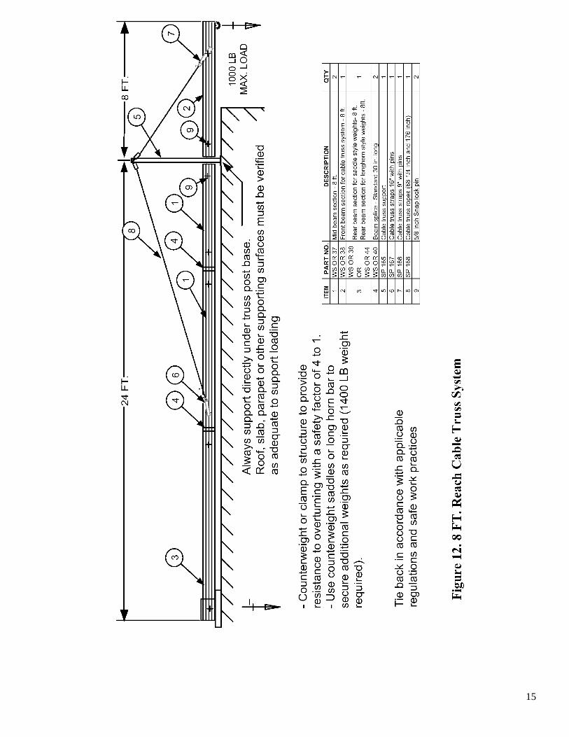
1. Installation and use of the 8’ reach Cable Truss System requires a clear space of at least 24 feet behind
the parapet. The Cable Truss System is assembled in the sequence: Rear Beam, Beam Splice, Mid
Beam, Beam Splice, second Mid Beam, Cable Truss Mast and Front Beam (see Figure 12).
2. Assemble the Rear Beam (WS OR 39 or WS OR 44) - Beam Splice (WS OR 40) -
Mid Beam (WS OR 37) -Beam Splice (WS OR 40) - second Mid Beam (WS OR 37) by the assembly
procedure in Section 2.3.1. Ensure that the retaining pins are inserted and the retaining clips are locked.
15
16
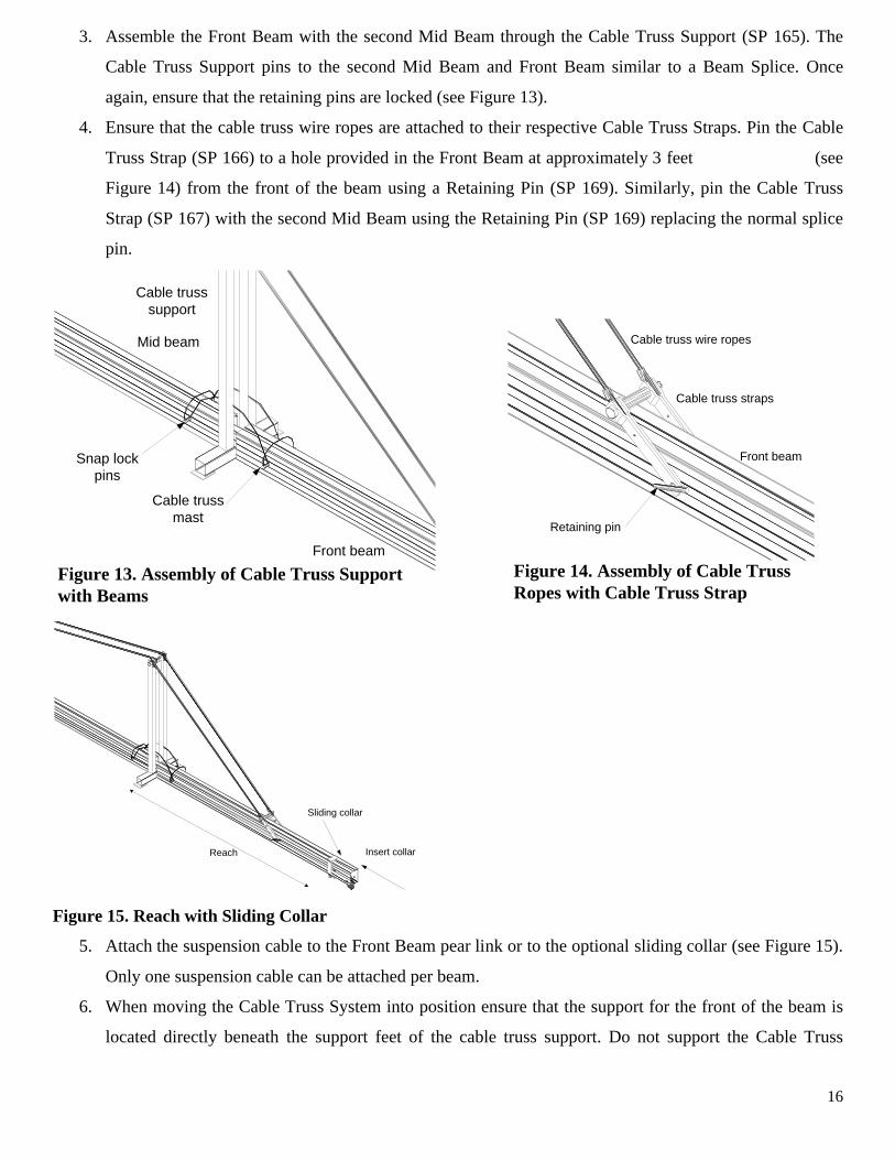
3. Assemble the Front Beam with the second Mid Beam through the Cable Truss Support (SP 165). The
Cable Truss Support pins to the second Mid Beam and Front Beam similar to a Beam Splice. Once
again, ensure that the retaining pins are locked (see Figure 13).
4. Ensure that the cable truss wire ropes are attached to their respective Cable Truss Straps. Pin the Cable
Truss Strap (SP 166) to a hole provided in the Front Beam at approximately 3 feet (see
Figure 14) from the front of the beam using a Retaining Pin (SP 169). Similarly, pin the Cable Truss
Strap (SP 167) with the second Mid Beam using the Retaining Pin (SP 169) replacing the normal splice
pin.
Cable truss wire ropes
Cable truss straps
Front beam
Retaining pin
Figure 14. Assembly of Cable TrussRopes with Cable Truss Strap
Mid beam
Snap lockpins
Cable trussmast
Front beam
Cable trusssupport
Figure 13. Assembly of Cable Truss Supportwith Beams
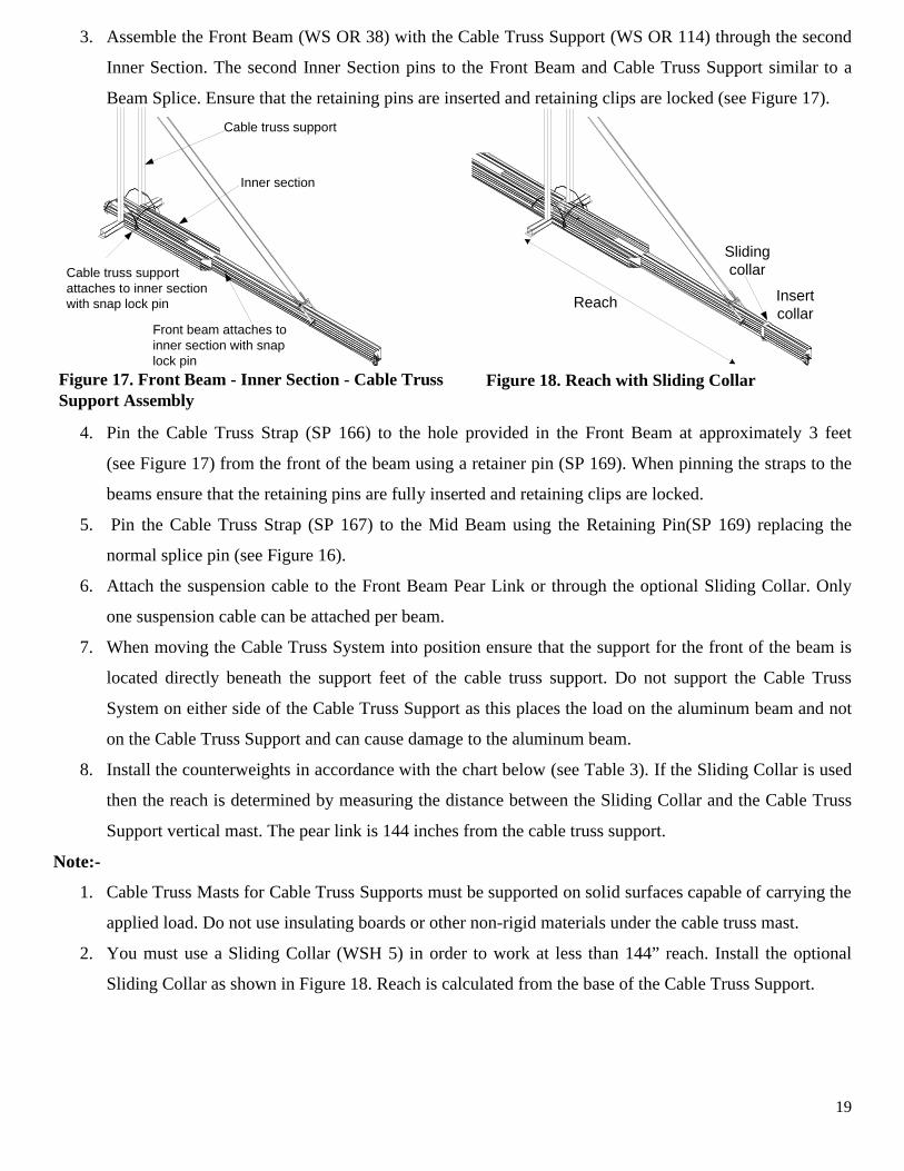
Sliding collar
Insert collarReach
Figure 15. Reach with Sliding Collar
5. Attach the suspension cable to the Front Beam pear link or to the optional sliding collar (see Figure 15).
Only one suspension cable can be attached per beam.
6. When moving the Cable Truss System into position ensure that the support for the front of the beam is
located directly beneath the support feet of the cable truss support. Do not support the Cable Truss
17
System on either side of the Cable Truss Support as this places the load on the aluminum beam and not
on the Cable Truss Support and can cause damage to the aluminum beam.
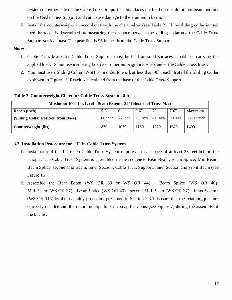
7. Install the counterweights in accordance with the chart below (see Table 2). If the sliding collar is used
then the reach is determined by measuring the distance between the sliding collar and the Cable Truss
Support vertical mast. The pear link is 96 inches from the Cable Truss Support.
Note:-
1. Cable Truss Masts for Cable Truss Supports must be held on solid surfaces capable of carrying the
applied load. Do not use insulating boards or other non-rigid materials under the Cable Truss Mast.
2. You must use a Sliding Collar (WSH 5) in order to work at less than 96” reach. Install the Sliding Collar
as shown in Figure 15. Reach is calculated from the base of the Cable Truss Support.
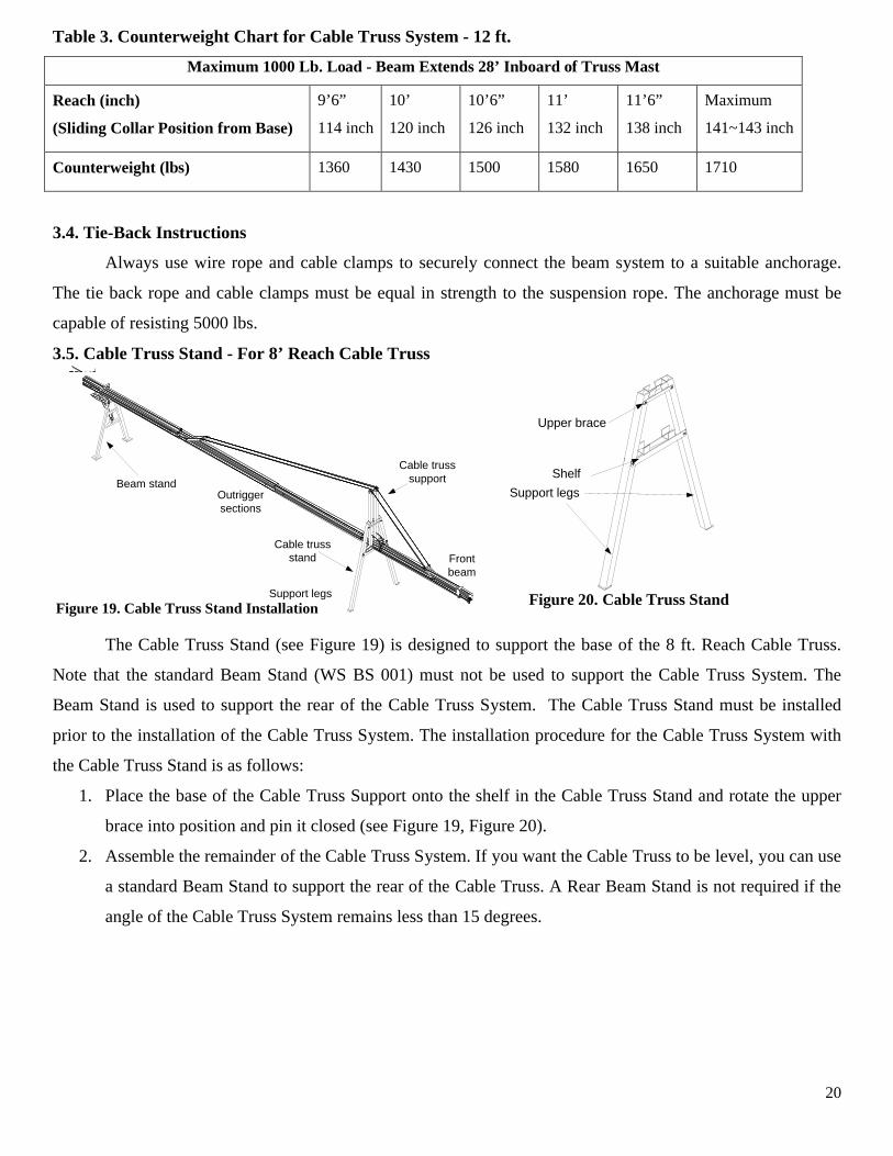
Table 2. Counterweight Chart for Cable Truss System - 8 ft.
Maximum 1000 Lb. Load - Beam Extends 24’ Inboard of Truss Mast
Reach (inch)
(Sliding Collar Position from Base)
5’6”
60 inch
6’
72 inch
6’6”
78 inch
7’
84 inch
7’6”
90 inch
Maximum
93~95 inch
Counterweight (lbs) 870 1050 1130 1220 1320 1400
3.3. Installation Procedure for - 12 ft. Cable Truss System
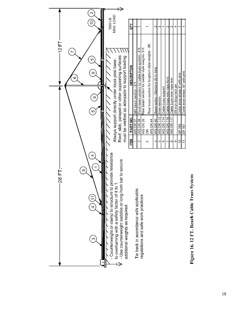
1. Installation of the 12’ reach Cable Truss System requires a clear space of at least 28 feet behind the
parapet. The Cable Truss System is assembled in the sequence: Rear Beam, Beam Splice, Mid Beam,
Beam Splice, second Mid Beam, Inner Section, Cable Truss Support, Inner Section and Front Beam (see
Figure 16).
2. Assemble the Rear Beam (WS OR 39 or WS OR 44) - Beam Splice (WS OR 40)-
Mid Beam (WS OR 37) - Beam Splice (WS OR 40) - second Mid Beam (WS OR 37) - Inner Section
(WS OR 113) by the assembly procedure presented in Section 2.3.1. Ensure that the retaining pins are
correctly inserted and the retaining clips lock the snap lock pins (see Figure 7) during the assembly of
the beams.
18
19
3. Assemble the Front Beam (WS OR 38) with the Cable Truss Support (WS OR 114) through the second
Inner Section. The second Inner Section pins to the Front Beam and Cable Truss Support similar to a
Beam Splice. Ensure that the retaining pins are inserted and retaining clips are locked (see Figure 17).
Cable truss support
Inner section
Front beam attaches toinner section with snaplock pin
Cable truss supportattaches to inner sectionwith snap lock pin