MAHARASHTRA STATE BOARD OF TECHNICAL EDUCATION (Autonomous) (ISO/IEC - 27001 - 2013 Certified) WINTER– 18 EXAMINATION Model Answer Subject Name: Design and Drawing of Auto Components Subject Code: _________________________________________________________________________________________________ Page 1 of 29 17525 Important Instructions to examiners: 1) The answers should be examined by key words and not as word-to-word as given in the model answer scheme. 2) The model answer and the answer written by candidate may vary but the examiner may try to assess the understanding level of the candidate. 3) The language errors such as grammatical, spelling errors should not be given more Importance (Not applicable for subject English and Communication Skills. 4) While assessing figures, examiner may give credit for principal components indicated in the figure. The figures drawn by candidate and model answer may vary. The examiner may give credit for any equivalent figure drawn. 5) Credits may be given step wise for numerical problems. In some cases, the assumed constant values may vary and there may be some difference in the candidate’s answers and model answer. 6) In case of some questions credit may be given by judgement on part of examiner of relevant answer based on candidate’s understanding. 7) For programming language papers, credit may be given to any other program based on equivalent concept. Q. No Sub Q.N. Answer Marking Scheme 1 A) Attempt any THREE 12 1A i) State eight considerations in machine design 04 Answer: Design considerations in machine design: (Any eight) 1. Types of loads and stresses caused by the load. 2. Motion of parts and kinetics of machine. 3. Material selection criteria based on cost, properties etc. 4. Shape and size of parts. 5. Frictional resistance and lubrication. 6. Use of standard parts. 7. Safety operations. 8. Work shop facilities available. 9. Manufacturing cost. 10. Convenient of assembly and transportation. 04 1A ii) Define standardization and state the four advantages of it. 04 Answer: (Definition- 2mark, Advantages-2 mark) Standardization: - It is defined as obligatory norms to which various characteristics of a product should conform. The characteristics include materials, dimensions and shape of the component, method of testing and method of marking, packing and storing of the product. Advantages of Standardization:- (Any four) 1. Mass production is easy. 2. Rate of production increases. 02 02
Transcript
MAHARASHTRA STATE BOARD OF TECHNICAL EDUCATION (Autonomous)
(ISO/IEC - 27001 - 2013 Certified)
WINTER– 18 EXAMINATION
Model Answer
Subject Name: Design and Drawing of Auto Components Subject Code: _________________________________________________________________________________________________
Page 1 of 29
17525
Important Instructions to examiners:
1) The answers should be examined by key words and not as word-to-word as given in the model answer
scheme.
2) The model answer and the answer written by candidate may vary but the examiner may try to assess the
understanding level of the candidate.
3) The language errors such as grammatical, spelling errors should not be given more Importance (Not
applicable for subject English and Communication Skills.
4) While assessing figures, examiner may give credit for principal components indicated in the figure. The
figures drawn by candidate and model answer may vary. The examiner may give credit for any equivalent
figure drawn.
5) Credits may be given step wise for numerical problems. In some cases, the assumed constant values may
vary and there may be some difference in the candidate’s answers and model answer.
6) In case of some questions credit may be given by judgement on part of examiner of relevant answer based
on candidate’s understanding.
7) For programming language papers, credit may be given to any other program based on equivalent concept.
Q.
No
Sub
Q.N.
Answer Marking
Scheme
1 A) Attempt any THREE 12
1A i) State eight considerations in machine design 04
Answer:
Design considerations in machine design: (Any eight)
1. Types of loads and stresses caused by the load.
2. Motion of parts and kinetics of machine.
3. Material selection criteria based on cost, properties etc.
4. Shape and size of parts.
5. Frictional resistance and lubrication.
6. Use of standard parts.
7. Safety operations.
8. Work shop facilities available.
9. Manufacturing cost.
10. Convenient of assembly and transportation.
04
1A ii) Define standardization and state the four advantages of it. 04
Answer: (Definition- 2mark, Advantages-2 mark)
Standardization: - It is defined as obligatory norms to which various characteristics of a product should conform. The characteristics include materials, dimensions and shape of the component, method of testing and method of marking, packing and storing of the product.
Advantages of Standardization:- (Any four)
1. Mass production is easy.
2. Rate of production increases.
02
02
MAHARASHTRA STATE BOARD OF TECHNICAL EDUCATION (Autonomous)
(ISO/IEC - 27001 - 2013 Certified)
WINTER– 18 EXAMINATION
Model Answer
Subject Name: Design and Drawing of Auto Components Subject Code: _________________________________________________________________________________________________
Page 2 of 29
17525
3. Reduction in labour cost.
4. Limits the variety of size and shape of product.
5. Overall reduction in cost of production.
6. Improves overall performance, quality and efficiency of product.
7. Better utilization of labour, machine and time.
(a) Shaft : shaft is a rotating element which is used to transmit power from one place
to another.
(b) Axle: An axle is a stationary machine element and is used for the transmission of
bending moment only. It simply act as a support for some rotating body such as
hoisting drum, a car wheel or a rope sheave.
(c) Spindle : spindle is a short shaft that imparts motion either to a cutting tool or to
a work piece.
(d) Key: Key is a piece of mild steel inserted between the shaft and hub or boss of
the pulley to connect these together in order to prevent relative motion between
them.
04
1A iv) List the important factors that influence the magnitude of F.O.S. 04
Answer : (Any Four – 1 Marks Each) The factors that influence the magnitude of factor
of safety: 1. The reliability of applied load and nature of load,
2. The reliability of the properties of material and change of these properties during service,
3. The reliability of test results & accuracy of application of these results to actual machine
parts,
4. The certainty as to exact mode of failure,
5. The extent of simplifying assumptions,
6. The extent of localized stresses,
7. The extent of initial stresses setup during manufacture,
8. The extent of loss of property if failure occurs,
9. The extent of loss of life if failure occurs.
04
1 B) Attempt any ONE: 06
1B i) The rear axle shaft connecting differential to side wheel is required to transmit 40
kW at 1600 rpm. If Maximum torque is two times average torque and allowable
shear stress is 80 N/mm2 for axle shaft material, find out diameter of axle shaft if
(a) shaft is solid (b) shaft is hollow with outside diameter 1.6 times inside diameter.
06
Given Data:
P = 40 kW = 40 X 103 W
N = 1600 rpm,
Tmax = 2 Tavg,
τ = 80 N/mm2 ,
MAHARASHTRA STATE BOARD OF TECHNICAL EDUCATION (Autonomous)
(ISO/IEC - 27001 - 2013 Certified)
WINTER– 18 EXAMINATION
Model Answer
Subject Name: Design and Drawing of Auto Components Subject Code: _________________________________________________________________________________________________
Page 3 of 29
17525
(a) Shaft is solid
Let d = diameter of shaft
We know that torque transmitted by shaft,
Tavg = 𝑷 𝑿 𝟔𝟎
𝟐 𝝅 𝑵 =
𝟒𝟎𝟎𝟎𝟎 𝑿 𝟔𝟎
𝟐 𝝅 𝑿 𝟏𝟔𝟎𝟎 = 238.73 N-m = 238.73 X 10
3 N-mm
Max torque transmitted by shaft
Tmax = 2 X Tavg = 2X 238.73 X 103
= 477.46 X 10³ N-mm
We also know that max. torque transmitted by shaft,
Tmax = 𝝅
𝟏𝟔 X d
3 X τ
477.46 X 103
= 𝝅
𝟏𝟔 X d
3 X 80
∴ d = 31.20 mm say 32 mm (b) Shaft is hollow with outside diameter 1.6 times inside diameter.
Let di = inside diameter of hollow shaft
do = outside diameter of shaft = 1.6 di
k = di/ do = di/ 1.6 di = 0.625
we know that for hollow shaft max. torque transmitted by shaft,
Tmax = 𝝅
𝟏𝟔 (do)
3 x τ X (1 - k
4)
477.46 X 103
= 𝝅
𝟏𝟔 (do)
3 X 80 X (1 – 0.625
4)
∴ do = 32.97 mm say 34 mm
And di = 34 X 0.625 = 21.25 mm
01
01
01
01
01
01
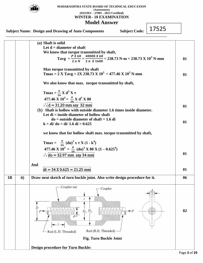
1B ii) Draw neat sketch of turn buckle joint. Also write design procedure for it. 06
Fig. Turn Buckle Joint
Design procedure for Turn Buckle:
02
MAHARASHTRA STATE BOARD OF TECHNICAL EDUCATION (Autonomous)
(ISO/IEC - 27001 - 2013 Certified)
WINTER– 18 EXAMINATION
Model Answer
Subject Name: Design and Drawing of Auto Components Subject Code: _________________________________________________________________________________________________
Page 4 of 29
17525
01
01
01
MAHARASHTRA STATE BOARD OF TECHNICAL EDUCATION (Autonomous)
(ISO/IEC - 27001 - 2013 Certified)
WINTER– 18 EXAMINATION
Model Answer
Subject Name: Design and Drawing of Auto Components Subject Code: _________________________________________________________________________________________________
Page 5 of 29
17525
01
2. Attempt any FOUR: 16
2 i) Define fatigue and endurance limit. Draw the S-N curve for cyclic loading. 04
i) Fatigue: When the system or element is subjected to fluctuating (repeated) loads, the
material of system or element tends to fails below yield stresses by the formation of
progressive crack this failure is called as fatigue. The failure may occur without prior
indication. The fatigue of material is affected by the size of component, relative magnitude
of static and fluctuating load and number of load reversals.
ii) Endurance limit: It is defined as maximum value of the completely reversed bending
stress which a polished standard specimen can withstand without failure, for infinite number
of cycles (usually 107
cycles).
The term endurance limit is used for reversed bending cycle only. The endurance limit of material
depends on:
Fig. S-N curve
01
01
02
MAHARASHTRA STATE BOARD OF TECHNICAL EDUCATION (Autonomous)
(ISO/IEC - 27001 - 2013 Certified)
WINTER– 18 EXAMINATION
Model Answer
Subject Name: Design and Drawing of Auto Components Subject Code: _________________________________________________________________________________________________
Page 6 of 29
17525
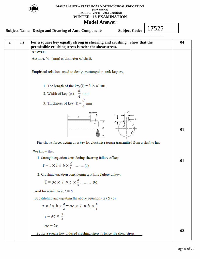
2 ii) For a square key equally strong in shearing and crushing . Show that the
permissible crushing stress is twice the shear stress.
04
01
01
02
MAHARASHTRA STATE BOARD OF TECHNICAL EDUCATION (Autonomous)
(ISO/IEC - 27001 - 2013 Certified)
WINTER– 18 EXAMINATION
Model Answer
Subject Name: Design and Drawing of Auto Components Subject Code: _________________________________________________________________________________________________
Page 7 of 29
17525
2 iii) Explain the two methods to make bolt of uniform strength. 04
Answer: Bolts of uniform strength:
When a bolt is subjected to shock loading, as in case of cylinder head bolt of an I.C. engine,
the resilience of bolt should be considered in order to prevent breakage at the threads. In
order to make the bolt of uniform strength, the shank of the bolt is reduced in diameter. the
shank diameter can be reduced in following two manners:
1. If the shank of the bolt is turned down to a diameter equal or even slightly less than
the core diameter of the thread (Dc) as shown in Fig. (b), then shank of the bolt will
undergo a higher stress. This means that a shank will absorb a large portion of the
energy, thus relieving the material at the sections near the thread. The bolt, in this
way, becomes stronger and lighter and it increases the shock absorbing capacity of
the bolt because of an increased modulus of resilience. This gives us bolts of uniform
strength. The resilience of a bolt may also be increased by increasing its length.
2. A second alternative method of obtaining the bolts of uniform strength is shown in
Fig. (c). In this method, an axial hole is drilled through the head as far as the thread
portion such that the area of the shank becomes equal to the root area of the thread.
02
01
01
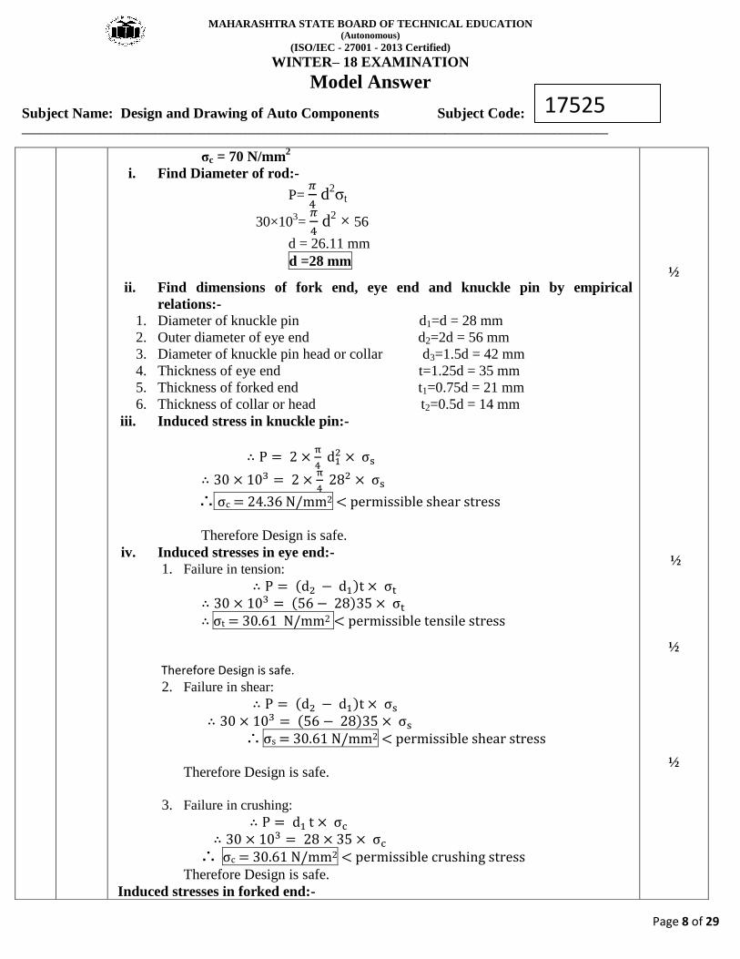
2 iv) A knuckle joint is required to withstand a tensile load of 30 kN. Design the joint if
the permissible stresses are 56 N/mm2 in tension, 40N/mm
2 in shear and 70 N/mm
2
in crushing respectively.
04
Given Data:
P = 30 × 103 N
σs = 40 N/mm2
σt = 56 N/mm2
MAHARASHTRA STATE BOARD OF TECHNICAL EDUCATION (Autonomous)
(ISO/IEC - 27001 - 2013 Certified)
WINTER– 18 EXAMINATION
Model Answer
Subject Name: Design and Drawing of Auto Components Subject Code: _________________________________________________________________________________________________
Page 8 of 29
17525
σc = 70 N/mm2
i. Find Diameter of rod:-
P= 𝜋
4 d
2σt
30×103=
𝜋
4 d
2 × 56
d = 26.11 mm
d =28 mm
ii. Find dimensions of fork end, eye end and knuckle pin by empirical
relations:-
1. Diameter of knuckle pin d1=d = 28 mm
2. Outer diameter of eye end d2=2d = 56 mm
3. Diameter of knuckle pin head or collar d3=1.5d = 42 mm
MAHARASHTRA STATE BOARD OF TECHNICAL EDUCATION (Autonomous)
(ISO/IEC - 27001 - 2013 Certified)
WINTER– 18 EXAMINATION
Model Answer
Subject Name: Design and Drawing of Auto Components Subject Code: _________________________________________________________________________________________________
3 i) Define lever. Describe three basic types of lever. 04
Answer: (Defination-1 mark, Types of lever with description -1 mark each) Definition:- A lever is a rigid rod or a bar capable of turning about a fixed point called
fulcrum.
The load W and the effort P may be applied to the lever in three different ways as shown in
Figure.
Types of leaver: First type, second type and third type levers shown in figure at (a), (b) and
(c) respectively.
a) First type lever: In the first type of levers, the fulcrum is in between the load and effort.
In this case, the effort arm is greater than load arm; therefore mechanical advantage obtained
is more than one.
Examples: Such type of levers are commonly found in bell cranked levers used in railway
04
MAHARASHTRA STATE BOARD OF TECHNICAL EDUCATION (Autonomous)
(ISO/IEC - 27001 - 2013 Certified)
WINTER– 18 EXAMINATION
Model Answer
Subject Name: Design and Drawing of Auto Components Subject Code: _________________________________________________________________________________________________
Page 10 of 29
17525
signaling arrangement, rocker arm in internal combustion engines, handle of a hand pump,
hand wheel of a punching press, beam of a balance, foot lever etc.
b) Second type lever: In the second type of levers, the load is in between the fulcrum
and effort. In this case, the effort arm is more than load arm; therefore the mechanical
advantage is more than one.
Examples: It is found in levers of loaded safety valves.
c) Third type lever: In the third type of levers, the effort is in between the fulcrum and load.
Since the effort arm, in this case, is less than the load arm, therefore the mechanical
advantage is less than one.
Examples: The use of such type of levers is not recommended in engineering practice.
However a pair of tongs, the treadle of a sewing machine etc. are examples of this type of
lever.
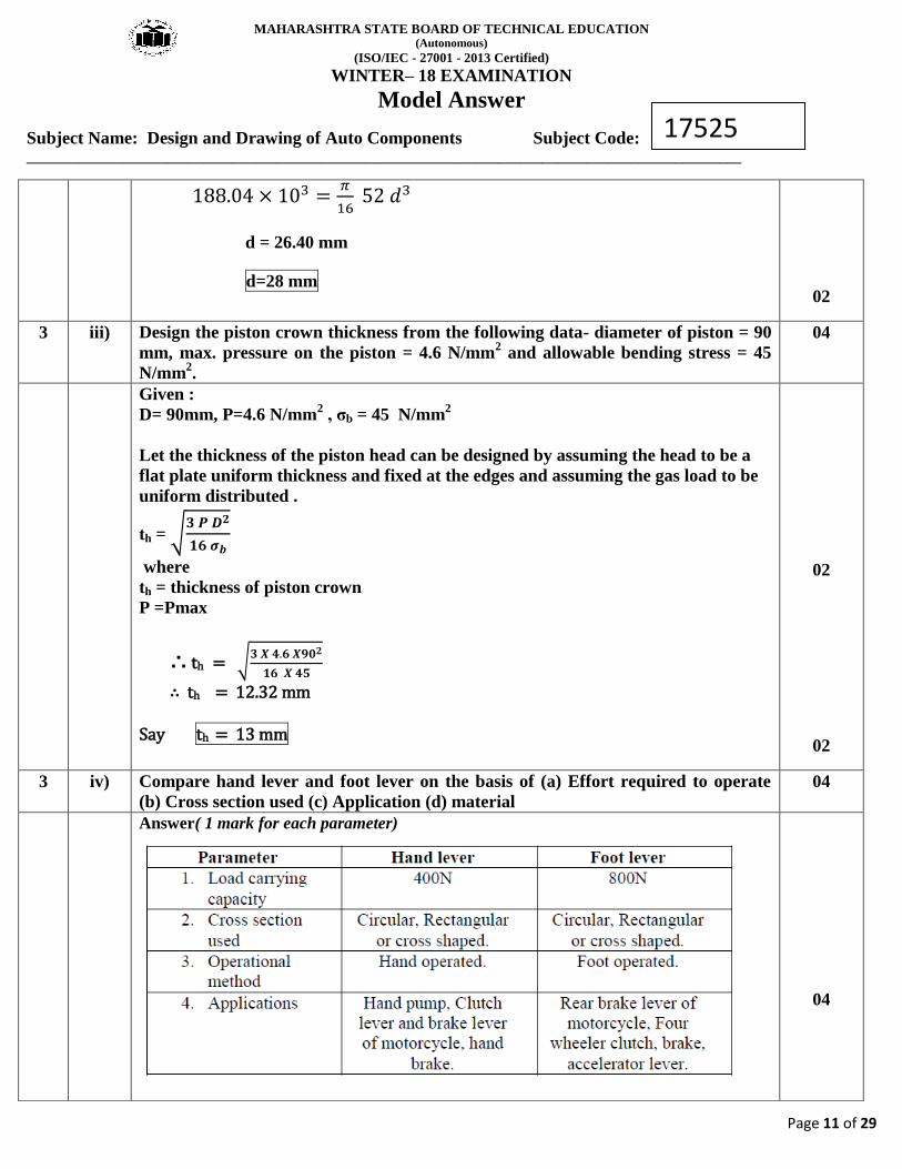
3 ii) Design a propeller shaft to transmit 8 kW at 6500 rpm with gear box reduction of
16:1. Assume shear stress fs = 52 N/mm2.
04
8 × 103 =2 𝜋 × 6500 × 𝑇𝑒
60
Answer: Given Data:
P= 8×10³W, N=6500rpm
G1=16:1, fs = σs=52 N/mm2
Now torque produced by the engine,
𝑃 =2 𝜋𝑁𝑇𝑒
60
𝑻𝒆 = 𝟏𝟏. 𝟕𝟓 𝐍𝐦 = 𝟏𝟏. 𝟕𝟓 × 𝟏𝟎𝟑 𝐍𝐦𝐦
Torque transmitted by the propeller shaft,
Tp = Te× G1
Tp = 11.75×103× 16
Tp = 188.04 × 10³
Nmm
Diameter of propeller shaft,
𝑇𝑝 =𝜋
16 𝜎𝑠 𝑑3
01
01
MAHARASHTRA STATE BOARD OF TECHNICAL EDUCATION (Autonomous)
(ISO/IEC - 27001 - 2013 Certified)
WINTER– 18 EXAMINATION
Model Answer
Subject Name: Design and Drawing of Auto Components Subject Code: _________________________________________________________________________________________________
Page 11 of 29
17525
188.04 × 103 =𝜋
16 52 𝑑3
d = 26.40 mm
d=28 mm
02
3 iii) Design the piston crown thickness from the following data- diameter of piston = 90
mm, max. pressure on the piston = 4.6 N/mm2 and allowable bending stress = 45
N/mm2.
04
Given :
D= 90mm, P=4.6 N/mm2 , σb = 45 N/mm
2
Let the thickness of the piston head can be designed by assuming the head to be a
flat plate uniform thickness and fixed at the edges and assuming the gas load to be
uniform distributed .
th = √𝟑 𝑷 𝑫𝟐
𝟏𝟔 𝝈𝒃
where
th = thickness of piston crown
P =Pmax
∴ th = √𝟑 𝑿 𝟒.𝟔 𝑿𝟗𝟎𝟐
𝟏𝟔 𝑿 𝟒𝟓
∴ th = 12.32 mm Say th = 13 mm
02
02
3 iv) Compare hand lever and foot lever on the basis of (a) Effort required to operate
(b) Cross section used (c) Application (d) material
04
Answer( 1 mark for each parameter)
04
MAHARASHTRA STATE BOARD OF TECHNICAL EDUCATION (Autonomous)
(ISO/IEC - 27001 - 2013 Certified)
WINTER– 18 EXAMINATION
Model Answer
Subject Name: Design and Drawing of Auto Components Subject Code: _________________________________________________________________________________________________
Page 12 of 29
17525
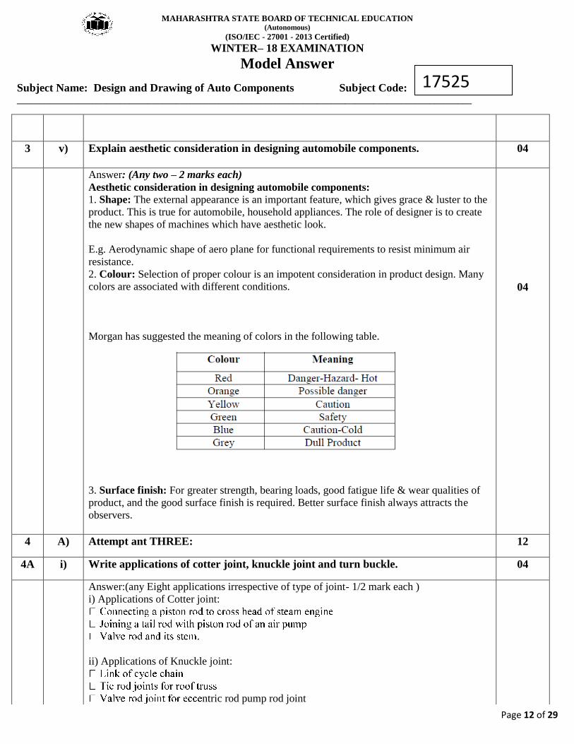
3 v) Explain aesthetic consideration in designing automobile components. 04
Answer: (Any two – 2 marks each)
Aesthetic consideration in designing automobile components: 1. Shape: The external appearance is an important feature, which gives grace & luster to the
product. This is true for automobile, household appliances. The role of designer is to create
the new shapes of machines which have aesthetic look.
E.g. Aerodynamic shape of aero plane for functional requirements to resist minimum air
resistance.
2. Colour: Selection of proper colour is an impotent consideration in product design. Many
colors are associated with different conditions.
Morgan has suggested the meaning of colors in the following table.
3. Surface finish: For greater strength, bearing loads, good fatigue life & wear qualities of
product, and the good surface finish is required. Better surface finish always attracts the
observers.
04
4 A) Attempt ant THREE: 12
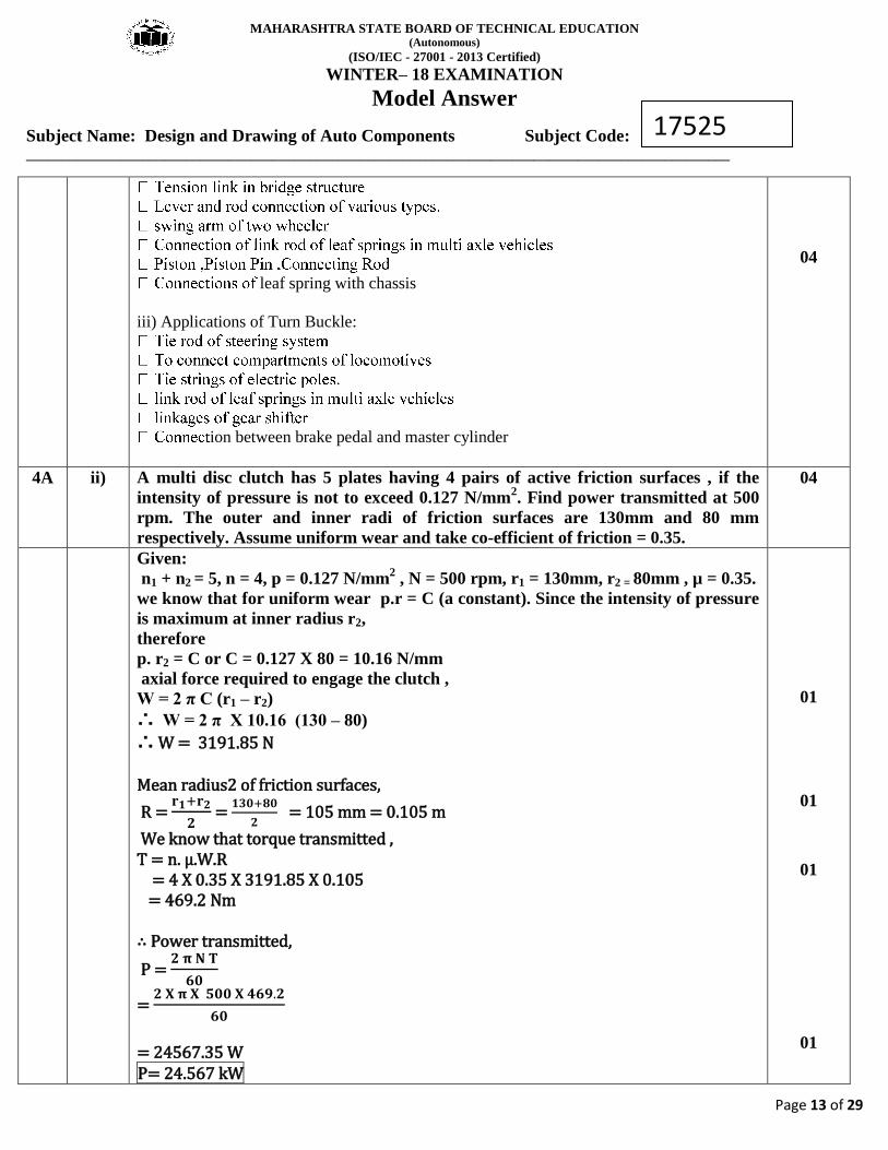
4A i) Write applications of cotter joint, knuckle joint and turn buckle. 04
Answer:(any Eight applications irrespective of type of joint- 1/2 mark each )
i) Applications of Cotter joint:
ii) Applications of Knuckle joint:
ntric rod pump rod joint
MAHARASHTRA STATE BOARD OF TECHNICAL EDUCATION (Autonomous)
(ISO/IEC - 27001 - 2013 Certified)
WINTER– 18 EXAMINATION
Model Answer
Subject Name: Design and Drawing of Auto Components Subject Code: _________________________________________________________________________________________________
Page 13 of 29
17525
leaf spring with chassis
iii) Applications of Turn Buckle:
ion between brake pedal and master cylinder
04
4A ii) A multi disc clutch has 5 plates having 4 pairs of active friction surfaces , if the
intensity of pressure is not to exceed 0.127 N/mm2. Find power transmitted at 500
rpm. The outer and inner radi of friction surfaces are 130mm and 80 mm
respectively. Assume uniform wear and take co-efficient of friction = 0.35.
04
Given:
n1 + n2 = 5, n = 4, p = 0.127 N/mm2 , N = 500 rpm, r1 = 130mm, r2 = 80mm , µ = 0.35.
we know that for uniform wear p.r = C (a constant). Since the intensity of pressure
is maximum at inner radius r2,
therefore
p. r2 = C or C = 0.127 X 80 = 10.16 N/mm
axial force required to engage the clutch ,
W = 2 π C (r1 – r2)
∴ W = 2 π X 10.16 (130 – 80)
∴ W = 3191.85 N Mean radius2 of friction surfaces,
R = 𝐫𝟏+𝐫𝟐
𝟐 =
𝟏𝟑𝟎+𝟖𝟎
𝟐 = 105 mm = 0.105 m
We know that torque transmitted , T = n. µ.W.R = 4 X 0.35 X 3191.85 X 0.105 = 469.2 Nm ∴ Power transmitted,
P = 𝟐 𝛑 𝐍 𝐓
𝟔𝟎
= 𝟐 𝐗 𝛑 𝐗 𝟓𝟎𝟎 𝐗 𝟒𝟔𝟗.𝟐
𝟔𝟎
= 24567.35 W P= 24.567 kW
01
01
01
01
MAHARASHTRA STATE BOARD OF TECHNICAL EDUCATION (Autonomous)
(ISO/IEC - 27001 - 2013 Certified)
WINTER– 18 EXAMINATION
Model Answer
Subject Name: Design and Drawing of Auto Components Subject Code: _________________________________________________________________________________________________
Page 14 of 29
17525
4A iii) Draw stress diagram for ductile material and state its importance. 04
Importance of Stress-Strain diagram for ductile material: The most important properties
of materials are strength, elasticity, stiffness, ductility etc. From stress-strain diagram,
material properties like ultimate strength, elastic limit, ductility etc. can be found out. Hence,
these values can be used for designing and selection of proper material for machine design.
Figure. Stress-Strain diagram for ductile material
02
02
4A iv) Define indicated power and brake power of an engine cylinder. 04
Answer: Indicated Power The power developed inside the cylinder is known as indicated
power. It is called as indicated power because it is measured from indicator diagram.
Where
02
MAHARASHTRA STATE BOARD OF TECHNICAL EDUCATION (Autonomous)
(ISO/IEC - 27001 - 2013 Certified)
WINTER– 18 EXAMINATION
Model Answer
Subject Name: Design and Drawing of Auto Components Subject Code: _________________________________________________________________________________________________
Page 15 of 29
17525
02
4 B) Attempt any ONE: 06
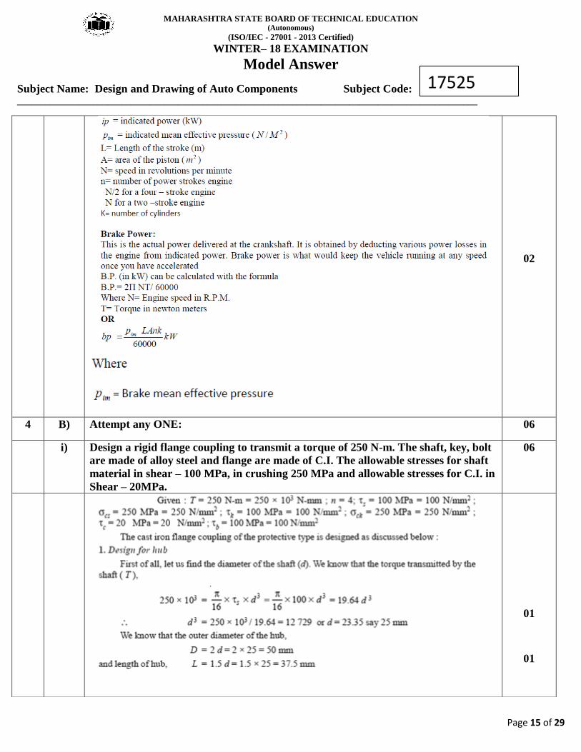
i) Design a rigid flange coupling to transmit a torque of 250 N-m. The shaft, key, bolt
are made of alloy steel and flange are made of C.I. The allowable stresses for shaft
material in shear – 100 MPa, in crushing 250 MPa and allowable stresses for C.I. in
Shear – 20MPa.
06
01
01
MAHARASHTRA STATE BOARD OF TECHNICAL EDUCATION (Autonomous)
(ISO/IEC - 27001 - 2013 Certified)
WINTER– 18 EXAMINATION
Model Answer
Subject Name: Design and Drawing of Auto Components Subject Code: _________________________________________________________________________________________________
Page 16 of 29
17525
2.Design for Key
From key properties, we find that the proportions of key for 25 mm shaft are,
4.Design for bolts
Assuming no of bolts n = 4
01
01
01
MAHARASHTRA STATE BOARD OF TECHNICAL EDUCATION (Autonomous)
(ISO/IEC - 27001 - 2013 Certified)
WINTER– 18 EXAMINATION
Model Answer
Subject Name: Design and Drawing of Auto Components Subject Code: _________________________________________________________________________________________________
Page 17 of 29
17525
01
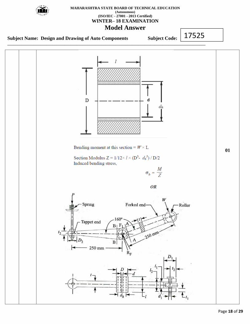
ii) Explain design procedure of a rocker arm for operating exhaust valve. 06
Considering the bearing of the fulcrum pin. We know that load on the fulcrum pin (RF),
External diameter of the boss,
D = 2 d
Internal diameter of the hole in the lever,
dh= d + (2 × 3)
check the induced bending stress for the section of the boss at the fulcrum
01
01
01
01
01
MAHARASHTRA STATE BOARD OF TECHNICAL EDUCATION (Autonomous)
(ISO/IEC - 27001 - 2013 Certified)
WINTER– 18 EXAMINATION
Model Answer
Subject Name: Design and Drawing of Auto Components Subject Code: _________________________________________________________________________________________________
Page 18 of 29
17525
01
MAHARASHTRA STATE BOARD OF TECHNICAL EDUCATION (Autonomous)
(ISO/IEC - 27001 - 2013 Certified)
WINTER– 18 EXAMINATION
Model Answer
Subject Name: Design and Drawing of Auto Components Subject Code: _________________________________________________________________________________________________
Page 19 of 29
17525
In designing a rocker arm the following procedure may be followed :
1. Rocker arm is usually I-Section it is subjected to bending moment. To find bending
moment it is assumed that the arm of the lever extends from point of application of
load to center of pivot.
2. The ratio of length to the diameter of the fulcrum pin and roller pin is taken as 1.25.
The permissible bearing pressure on this pin is taken from 3.5 to 6 N/mm2.
3. The outside diameter of boss at fulcrum is usually taken twice the diameter of the
pin at fulcrum. The boss is provided with a 3mm thick phosphor bronze bush to take
up the wear.
4. One end of rocker arm has a forked end to receive roller.
5. The outside diameter of the eye at the forked end is also taken as twice the diameter
of pin. The diameter of roller is slightly larger (at least 3mm more) than the diameter
of eye at the forked end. The radial thickness of each eye of the forked end is taken
half the diameter of pin. Some clearance about 1.5mm must be provided between the
roller and the eye at the forked end so that roller can move freely. The pin should,
therefore be checked for bending.
6. The other end of rocker arm (i.e. tappet end) is made circular to receive the tappet
which is a stud with a lock nut. The outside diameter of the circular arm is taken as
twice the diameter of the stud. The depth of section is also taken twice the diameter of
stud.
5 Attempt any TWO: 16
5 i) A 4-stroke diesel engine has the following specifications:
Brake power =6 kW, speed = 1200 rpm, Indicated mean effective pressure = 0.35
N/mm2, Mechanical efficiency = 80 %. Determine,
(a) Bore and length of cylinder
(b) Thickness of cylinder head
08
Given:
B.P. = 6 kW = 6000 W
N = 1200 rpm
n = 1200/2 = 600 rpm …………………..…… for four stroke engine
Pm = 0.35 N/mm2
ηm = 80 % = 0.8
for cylinder cover σt = 52N/mm2……………………………....Assumed
Length of stroke L = 1.5 D= 1.5 D/ 1000 m……………………Assumed
1. Bore and Length of cylinder
Let D = bore of cylinder in mm
A = cross sectional Area of cylinder
MAHARASHTRA STATE BOARD OF TECHNICAL EDUCATION (Autonomous)
(ISO/IEC - 27001 - 2013 Certified)
WINTER– 18 EXAMINATION
Model Answer
Subject Name: Design and Drawing of Auto Components Subject Code: _________________________________________________________________________________________________
Page 20 of 29
17525
= 𝝅
𝟒 D
2
We know that Indicated Power
I.P. = 𝑩.𝑷.
𝜼𝒎 =
𝟔𝟎𝟎𝟎
𝟎.𝟖 = 7500 W
We also know that
I.P. = 𝑷𝒎 𝑳 𝑨 𝒏
𝟔𝟎
7500 = 𝟎.𝟑𝟓 𝑿 𝟏.𝟓 𝑫 𝑿 𝝅𝑫𝟐 𝑿 𝟔𝟎𝟎
𝟔𝟎 𝑿 𝟏𝟎𝟎𝟎 𝑿 𝟒
7500 = 4.12 x 10⁻³
D3
D3 =
𝟕𝟓𝟎𝟎
𝟒.𝟏𝟐 𝑿 𝟏𝟎−𝟑
D3 = 1818.91 X 10
3
D = 122.06 mm
Say D = 124 mm
L = 1.5 D = 1.5 X 124 = 186 mm
Taking a clearance on both sides of the cylinder equal to 15% of the stroke,
therefore length of the cylinder,
Length of cylinder = 1.15 X L = 1.15 X 186 = 213.9 = 214 mm
th = D √𝑪 𝑿 𝑷
𝝈𝒕
th = 124 X √(𝟎.𝟏 𝑿 𝟑.𝟏𝟓)
𝟓𝟐
th = 9.65 mm
say th = 10 mm
01
02
01
01
01
02
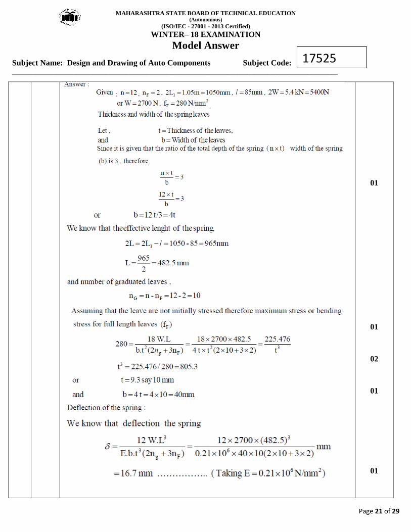
5 ii) A truck spring has 12 numbers of leaves , two of which are full length leaves. The
spring supports are 1.05 m apart and central band is 85 mm wide. The central load
is to be 5.4 kN with a permissible stress of 280 N/mm2. Determine the thickness of
and width of steel spring leaves. The ratio of total depth to width of the spring is 3.
Also determine the deflection of the spring.
08
MAHARASHTRA STATE BOARD OF TECHNICAL EDUCATION (Autonomous)
(ISO/IEC - 27001 - 2013 Certified)
WINTER– 18 EXAMINATION
Model Answer
Subject Name: Design and Drawing of Auto Components Subject Code: _________________________________________________________________________________________________
Page 21 of 29
17525
01
01
02
01
01
MAHARASHTRA STATE BOARD OF TECHNICAL EDUCATION (Autonomous)
(ISO/IEC - 27001 - 2013 Certified)
WINTER– 18 EXAMINATION
Model Answer
Subject Name: Design and Drawing of Auto Components Subject Code: _________________________________________________________________________________________________
Page 22 of 29
17525
01
01
5 iii) Explain the design procedure of connecting rod. 08
Answer: Design of Connecting Rod 1. Dimensions of cross-section of the connecting rod
According to Rankine’s formula,
01
01
01
MAHARASHTRA STATE BOARD OF TECHNICAL EDUCATION (Autonomous)
(ISO/IEC - 27001 - 2013 Certified)
WINTER– 18 EXAMINATION
Model Answer
Subject Name: Design and Drawing of Auto Components Subject Code: _________________________________________________________________________________________________
Page 23 of 29
17525
01
01
01
MAHARASHTRA STATE BOARD OF TECHNICAL EDUCATION (Autonomous)
(ISO/IEC - 27001 - 2013 Certified)
WINTER– 18 EXAMINATION
Model Answer
Subject Name: Design and Drawing of Auto Components Subject Code: _________________________________________________________________________________________________
Page 24 of 29
17525
01
01
6 Attempt any TWO 16
6 i) A four speed gear box is to constructed for providing the ratio 1.0, 1.46, 2.28 and
3.93 to 1as nearly as possible. The diametral pitch of gear is 3.25 mm and the
smallest pinion is to have at least 15 teeth.
Determine the suitable number of teeth of the different gear. Also calculate the
distance between main and layout shaft.
08
Answer: (Assume module of 3.25mm instead of diametral pitch)
01
01
01
MAHARASHTRA STATE BOARD OF TECHNICAL EDUCATION (Autonomous)
(ISO/IEC - 27001 - 2013 Certified)
WINTER– 18 EXAMINATION
Model Answer
Subject Name: Design and Drawing of Auto Components Subject Code: _________________________________________________________________________________________________
Page 25 of 29
17525
01
01
01
MAHARASHTRA STATE BOARD OF TECHNICAL EDUCATION (Autonomous)
(ISO/IEC - 27001 - 2013 Certified)
WINTER– 18 EXAMINATION
Model Answer
Subject Name: Design and Drawing of Auto Components Subject Code: _________________________________________________________________________________________________
Page 26 of 29
17525
02
6 ii) Determine the thickness of plain cylinder head for 0.4 m cylinder diameter. The
maximum gas pressure is 3.2 N/mm2. Design the studs and cylinder cover. Take
allowable tensile stress for cylinder cover and bolt equal to 42 N/mm2 and 63
N/mm2 repectively.
08
Given :
D = 0.4 m = 400 mm,
MAHARASHTRA STATE BOARD OF TECHNICAL EDUCATION (Autonomous)
(ISO/IEC - 27001 - 2013 Certified)
WINTER– 18 EXAMINATION
Model Answer
Subject Name: Design and Drawing of Auto Components Subject Code: _________________________________________________________________________________________________
Page 27 of 29
17525
P = 3.2 N/mm2
C = 0.1 ………………………………Assumed.
σt(cylinder) = 42 N/mm2
σt(bolt) = 63 N/mm2
1. Thickness of Plain Cylinder
th = D √𝑪 𝑿 𝑷
𝝈𝒕(𝒄𝒚𝒍𝒊𝒏𝒅𝒆𝒓)
th = 400 x √𝟎.𝟏 𝑿 𝟑.𝟐
𝟒𝟐
th = 34.91 mm
say th = 35 mm
2. Design of studs and cylinder cover
Let d = nominal dia od stud
dc = core dia of stud (0.84 d)
σt(bolt) = 63 N/mm2
ns = no. of studs
we know that the force acting on the cylinder head (or on the studs)
= 𝝅
𝟒 X D
2 X P
= 𝝅
𝟒 X 400
2 X 3.2
= 402123.8 N
The number of studs usually taken between
ns = 0.01 D(i.e (0.01 X 400) + 4 = 8) and 0.02 D + 4 (i.e. (0.02 X 400) +4 = 12)
taking ns = 12
we know that resisting force offered by all the studs
402123.8 = ns X 𝝅
𝟒 (dc)
2 X σt(bolt) = 12 X
𝝅
𝟒 (0.84 d)
2 X 63
∴ d = 28.39 mm
∴ d = 30 mm
The pitch circle diameter of the stud (Dp) is taken as D + 3d
Dp = 400 + (3 X 30)
= 490 mm
We know that pitch of the studs
= 𝝅 𝑫𝒑
𝒏𝒔 =
𝝅 𝑿 𝟒𝟗𝟎
𝟏𝟐 = 128.28 mm
For leak proof joint , the pitch of the stud should lie between 19 √𝒅 to 28.5 √𝒅
Where d is nominal diameter of the stud.
01
02
01
02
01
MAHARASHTRA STATE BOARD OF TECHNICAL EDUCATION (Autonomous)
(ISO/IEC - 27001 - 2013 Certified)
WINTER– 18 EXAMINATION
Model Answer
Subject Name: Design and Drawing of Auto Components Subject Code: _________________________________________________________________________________________________
Page 28 of 29
17525
∴ minimum pitch of the stud
= 19 √𝒅 = 19 X √𝟑𝟎 = 104.06 mm
And maximum pitch of the stud
= 28.5 √𝒅 = 28.5 X √𝟑𝟎 = 156.10 mm
Since the pitch of the stud obtained above (i. e. 128.28 mm ) lies between 104.06 mm
and 156.10 mm, therefore size of the stud (d) calculated above is satisfactory.
∴ d = 30mm
01
6 iii) A single plate dry clutch transmit 8kW at 940 rpm, the axial pressure is limited to
0.7 N/mm2. If coefficient of friction is 0.25, find;
a) Mean radius and face width of friction lining assuming ratio of mean radius
to face width as 4 and
b) Outer and inner radii of clutch plate.
08
Given Data:
n = 2, Power P = 8kW = 8000 W,
N = 940 rpm
= (π/2) n µ P r
3
= (π/2) X 2 X 0.25 X 0.7 X r3
01
MAHARASHTRA STATE BOARD OF TECHNICAL EDUCATION (Autonomous)
(ISO/IEC - 27001 - 2013 Certified)
WINTER– 18 EXAMINATION
Model Answer
Subject Name: Design and Drawing of Auto Components Subject Code: _________________________________________________________________________________________________
Page 29 of 29
17525
= 0.5497 r3 N-mm……………………………………….(1)
Power Transmitted
P = 𝟐𝝅𝑵𝑻
𝟔𝟎
8000 = 𝟐𝝅 𝑿 𝟗𝟒𝟎 𝑿 𝑻
𝟔𝟎
∴ T = 81.27 N-m ∴ T = 81.27 X 10³ N-mm…………………………………………………(2) From equation (1) and (2)
r3 = 𝟖𝟏.𝟐𝟕 𝑿 𝟏𝟎𝟑
𝟎.𝟓𝟒𝟗𝟕
∴ r3 = 147.845 X 10³ ∴ r = 52.877 mm = 53 mm Approximately. Now face width of the friction lining
b = 𝒓
𝟒 =
𝟓𝟑
𝟒 = 13.25
we know that b = r1 – r2 = 13.25 mm………………………………………..(3)
r = 𝒓𝟏+𝒓𝟐
𝟐
∴ r1 + r2 = 2 r = 2 X 53 = 106mm ……………………….(4) Equating equations (3) and (4) r1 = 59.625 mm and r2 = 46.375 mm


![Lattice-Based SNARGs and their Application to More ... · [GGHRSW13, BR14] constants: skand 𝜎 on input ( ,ct,𝜋): 1. Verify the proof 𝜋that ctcorresponds to an evaluation](https://static.documents.pub/doc/80x56/5f7d5ec87c3fcc302b29f8e9/lattice-based-snargs-and-their-application-to-more-gghrsw13-br14-constants.jpg)