14 How to order | How to install mobile crane ropes | How to inspect 05/2014 CRANE WIRE ROPE I n s t a l l a t i o n a n d I n s p e c t i o n G u i d e Brought to you in cooperation with Python America
Transcript
Brought to you in cooperation with Python America 14
How to order | How to install mobile crane ropes | How to inspect
05
/2
01
4
CRANE WIRE ROPE
Installation and Inspection Guide
Brought to you in cooperation with Python America
Brought to you in cooperation with Python America
-2-
Criteria Required to order Wire Rope
When you ask your supplier for a wire rope these are the criteria required you must communicate:
Diameter: Must be given in either metric or imperial, e. g. 14mm or 9/16”. Do N O T convert metric to imperial orvice versa yourself. Look in your crane book and use the OEM stated size.
Construction or ClassThis is the construction of wire rope which takes the form of # of outer strands x # of wires per strand,e.g. 6x36 or 35x7. There are many types and it is important to understand the difference between classand construction. For example, if you ask for 6x19 wire rope, any construction within this class, 6x19,6x25, 6x26, is acceptable for your supplier to ship to you. If you want a particular CONSTRUCTION youMUST specify the exact type.
Grade:This is the tensile grade of the wires used to make the wire rope and is designated as follows:
IPS (Improved Plow Steel) or 1770 N/mm2 or Grade 110/120
EIPS (Extra Improved Plow Steel) or 1960 N/mm2 or Grade 115/125
EEIPS (Extra Extra Improved Plow Steel) or 2160 N/mm2 or Grade 130/140
Core Type:IWRC (Independent Wire Rope Core) or FC (Fiber Core)
Lay Direction / Lay Type:Lay direction is either left or right and the type can be lang(s) or regular lay. It will be written as follows:
RRL = Right Regular Lay
LRL = Left Regular Lay
LLL = Left Lang Lay
RLL = Right Lang Lay
In some instances the international designation will be used: These are equivalent to N.A. designationsas follows:
Right Regular Lay = sZLeft Regular Lay = zSLeft Lang Lay = sSRight Lang Lay = zZAlternate Lay = A
FinishBright or Galvanized
Brought to you in cooperation with Python America
-3-
Installation of Wire RopeForeword
In order to fully achieve the service life potential of highperformance and standard wire rope for demanding crane jobsthese step by step instructions should be followed. They areintended to prevent rope damage caused by kinks, untwisting,and loose strands, during handling and installation.
We realize that the ‘real world’ is not perfect. This applies alsoto wire rope installation.
It is impossible to cover ALL imaginable installation situations,location difficulties, and crane set ups. You will also find thatthese instructions are not very different from the installationprocedures of traditional style 6-strand or 19x7 ropes. Manyexperienced Riggers may find some of the following “old hat”. Ifyou notice any omissions or have ideas that we can incorporateinto this brochure we will be most appreciative.
For a complete version of our Inspection-, Handling-, Installation-, and Instruction Guideplease e-mail us at [email protected]
If you have to field cut a rope
After attaching 3 hose clamps on eitherside of the cut mark, blade cut the rope.
Do not use a grinding wheel but a steelcutting blade; e.g.Elastic # 80EHT230-2.
Usually, you do not need to re-cut a wire rope. However, youmay encounter situations where it becomes necessary to shortenthe rope.
In cutting any wire rope special care MUST be taken inseizing the rope end.Two methods are suggested:
1) Seizing the rope end with soft iron wire.2) Seizing the rope end with hose clamps.
After cutting the rope it is good practice to braze or weld therope ends to ensure that they don’t unravel. Leave the seizing onthe rope for added holding strength. Be careful not to damage theseizing while brazing.
Cutting a rope with a torch may result in both uneven endsand damage to the seizing causing the strands to open up.
Rope diameter up to 14 mm (9/16") may be cut with a FELCOC16 hand cutter.
After bladecutting mountupright in a vice
Carefully melt and fuse together allindividual wires.
Properly fused wire rope end. If notdamaged during the fusing procedureclamps shall be left attached to the rope.
If hose clamps got damaged or are toobulky for the installation you need toreplace all 3 of them with a wire seizing.
In comparison, these are factory fusedand tapered ends done with aspecialized machine.
Brought to you in cooperation with Python America
-4-
Unreeling of Wire Rope
When removing the rope from the shipping reel or coil, thereel or coil MUST rotate as the rope unwinds. Any attempt tounwind a rope from stationary reel or coil WILL result in a kinkedrope that is ruined beyond repair.
The following illustrations demonstrate the right and wrongway of unreeling a rope.
Special care must be taken not to drag the rope overobstacles, over a deflection shaft, or around corners.
Avoid large fleet angles between the shipping reel and thefirst sheave. The rope may roll in the sheave causing the ropeto unlay. This is particularly important for all DoPar-, langs lay,and non-rotating rope constructions.
Avoid reeving the rope through small deflection sheavesand avoid changing the plane from vertical to horizontaldirection.
If you have to unspool large and heavy wire rope, use abrake to keep a slight tension on the rope. NEVER let the ropego slack and form loops.
All of these precautions apply to high performance as wellas to standard 6-strand-, 19x7, 19x19, and 34x7 wire ropes.
If in doubt, contact your nearest factory authorized wire ropedistributor.
WRONG
RIGHT
Brought to you in cooperation with Python America
-5-
Use of Cable Grips
The most common method to install a wire rope. The typeof cable grip depends on the rope type and construction.
Non-rotating rope should be installed with a swivel betweenold and new ropes. The old rope may have developed torqueduring it’s working life and we must ensure that this torque isnot transferred to the new rope.
When using cable grips,the end of the grips have tobe tightly seized on to therope body to prevent
accidental slip-out of the rope. Alternately, you may wrapthe grip end with a strong reinforced industrial strengthadhesive tape.
Two cable grips with eye, connected to two ropes with a swivel. Use with non-rotating rope.
Open-end cable grip connected to two ropes. Most common for light ropes.
NEVER attach a RIGHT hand lay rope to a LEFT hand lay rope
Two cable grips with eye, connected to two ropes with a suitable length of fiber rope or a rope sling.
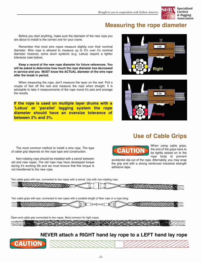
Measuring the rope diameter
Before you start anything, make sure the diameter of the new rope youare about to install is the correct one for your crane.
Remember that most wire ropes measure slightly over their nominaldiameter. Wire rope is allowed to measure up to 5% over it’s nominaldiameter however, some drum systems (e.g. Lebus) require a tightertolerance (see below).
Keep a record of the new rope diameter for future references. Youwill be asked to determine how much the rope diameter has decreasedin service and you MUST know the ACTUAL diameter of the wire ropeafter the break in period.
When measuring the rope, don’t measure the layer on the reel. Pull acouple of feet off the reel and measure the rope when straight. It isadvisable to take 4 measurements of the rope round it’s axis and averagethe results.
Right
Wrong
If the rope is used on multiple layer drums with a‘Lebus’ or ‘parallel’ lagging system the ropediameter should have an oversize tolerance ofbetween 2% and 3%.
Brought to you in cooperation with Python America
-6-
Winding the Rope onto the Drum
Break-in PeriodTensioning Rope Windings
Today, nearly all mobile cranes spool the rope in multiple layers onto agrooved drum. After installation it is very important to apply a sufficient pre-tension (5-10% of the rope’s WLL is a good measure). If wound with no tensionat all, the rope is subjected to premature crushing and flattening caused by the‘under load’ top layers.
If the first layer, or layers, are only used from time to time, they will loose theirtension on the drum and start to flatten out due to the high pressures of theloaded layers. Repeat this pre-tensioning procedure regularly.
Whatever you do, DO NOT run the rope through a ‘tightening’ device (seepicture), e.g. two wooden blocks clamped together. YOU WILL DESTROY THEROPE !
Rope is installed with proper pre-tension onto the drum. All layersare ‘hard’ wound and retain theirround shape.
The first 4 layers have lost theirtension and begin to deform andget crushed by the ‘hard’ woundtop layers. Regular pre-tensioning of ALL layers willminimize the crushing effect.
The rope has ‘pulled-in’ between the lowerwraps. Most often this happens when a‘slack’ line was spooled and the next‘heavy’ lift was spooled on top of such‘slack’ wraps.
The lower layers have collapsed, gotpushed sideways allowing the upperwraps to fill this gap ... the rope has‘pulled-in’.Proper rope pre-tensioning betweenlight- and heavy lifts will minimizesuch spooling problems.
This method oftightening the rope on to thedrum WILL destroy the rope.
Note: If your crane does have a ‘smooth-’ or ‘flat’ faced drumplease ask for our detailed instructions.
After installing the rope and with the boom fully extended run the rope through itsoperating cycle several times under light load and at reduced speed. Repeat this withincreasing load and speed a couple of times. This allows the rope to adjust itself to theworking conditions and enable all strands and wires to become seated.
Make sure you unspool the entire rope length down to the 3 safety wraps to pre-tension or pre-tightening therope to 5-10% of the rope’s WLL. This may also be required after the crane has been working using only a portionof the rope length.
Ideally, you should disconnect the rope end after the break-in-period to allow any possible torque and twistswhich may have developed during installation and the break-in-period to be released at the end connection. Whenusing non-rotating high performance wire rope constructions you may want to ask your rope supplier if it ispermitted to install a swivel between the rope end connection and the crane.
Brought to you in cooperation with Python America
-7-
Block tilting results in increasedrope fleet angle causing roperotation and thus block twisting;aside from severe sheave wear.Multipart lines should be reevedsymmetrically to avoid tilting.
Make sure the LOAD end of the rope is installed in linewith the pin; that is the STRAIGHT portion of the socketbowl. The ‘Terminator’ style wedge socket (red) is apreferred method.
Block Rotation
Block Tilting
Wedge Socket Installation
There are several reasons why a sheave block starts to rotate around itself.
a: Odd-part reeving is much less stable then even part reeving; e.g. a 3-part line reeve is less stable than a 4-part line reeve.
b: During rope installation torque or twist was introduced into the rope. c: For the lifting height the chosen rope type is not rotation resistant enough.d: Sheaves which are too tight and/or fleet angles are too large.
Relieving the rope twist when using non-rotating wire rope:Method A)Disconnect the rope end and rotate the rope end in the OPPOSITE direction of the block twist.If the block twisted 1/2 revolution (as in the illustration) rotate the rope end 180˙. If the blocktwisted 3 full revolutions rotate the rope end 3 times around itself. Re-attach the rope end andrun the rope (with no load attached) through the entire reeving to distribute the counter-turns.
Method B)If you use high performance rope constructions AND your rope supplier allows the use of aswivel you can install a one between the rope end fitting and the crane boom. A swivel will aidin relieving any possible twist. Once the twist is taken out of the rope you may lock the swivel,remove it entirely, or leave it permanently installed.
WRONG Installation RIGHT Installation
Non-Rotating RopesAttach hose clamp to all
rotation-resistant and non-
rotating wire rope to prevent
any slack caused by the
socket installation of outer- or
inner strands from travelling
along the entire rope length
Brought to you in cooperation with Python America
-8-
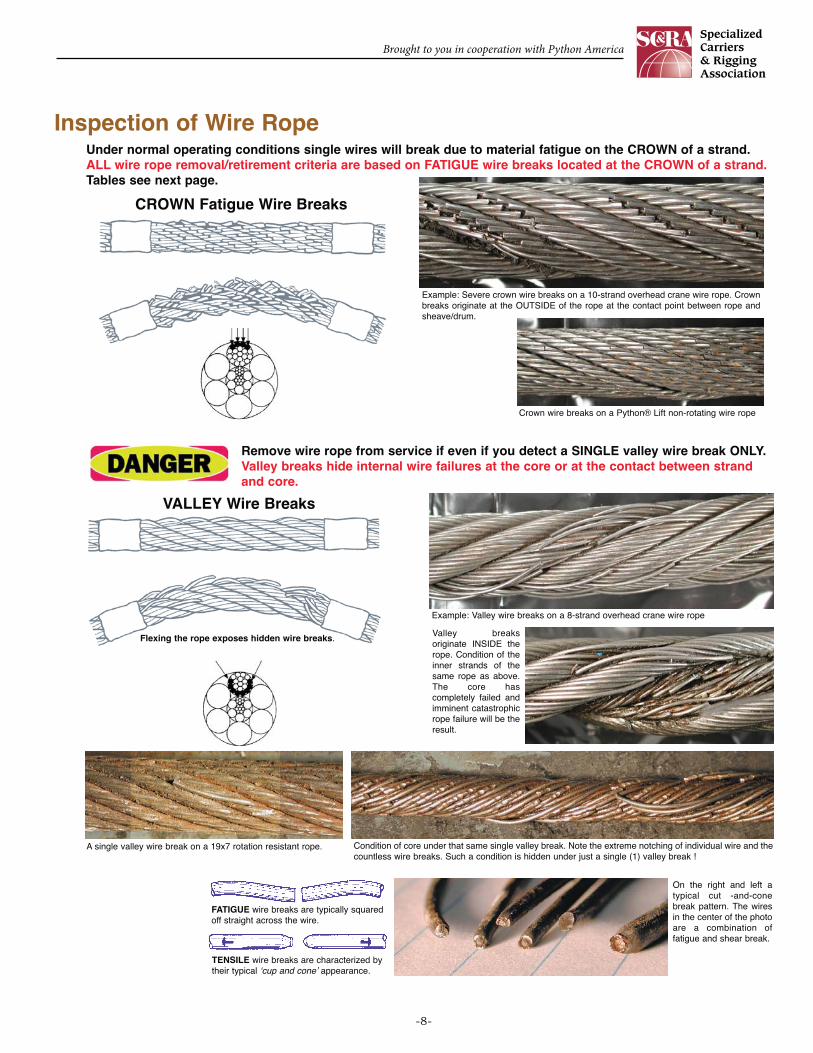
Inspection of Wire RopeUnder normal operating conditions single wires will break due to material fatigue on the CROWN of a strand.ALL wire rope removal/retirement criteria are based on FATIGUE wire breaks located at the CROWN of a strand.Tables see next page.
FATIGUE wire breaks are typically squaredoff straight across the wire.
TENSILE wire breaks are characterized bytheir typical ‘cup and cone’ appearance.
On the right and left atypical cut -and-conebreak pattern. The wiresin the center of the photoare a combination offatigue and shear break.
CROWN Fatigue Wire Breaks
VALLEY Wire Breaks
Flexing the rope exposes hidden wire breaks.
Remove wire rope from service if even if you detect a SINGLE valley wire break ONLY.Valley breaks hide internal wire failures at the core or at the contact between strandand core.
Crown wire breaks on a Python® Lift non-rotating wire rope
A single valley wire break on a 19x7 rotation resistant rope. Condition of core under that same single valley break. Note the extreme notching of individual wire and thecountless wire breaks. Such a condition is hidden under just a single (1) valley break !
Example: Severe crown wire breaks on a 10-strand overhead crane wire rope. Crownbreaks originate at the OUTSIDE of the rope at the contact point between rope andsheave/drum.
Example: Valley wire breaks on a 8-strand overhead crane wire rope
Valley breaksoriginate INSIDE therope. Condition of theinner strands of thesame rope as above.The core hascompletely failed andimminent catastrophicrope failure will be theresult.
Brought to you in cooperation with Python America
-9-
See below
4 in one lay 2 in onestrand inone lay
Overhead and Gantry Cranes
Tower Cranes
Portal and Pedestal Cranes
Mobile and Locomotive Cranes
Derricks
Winches
Floating Cranes and Derricks
Overhead Hoists (Underhung)
Self Erecting Tower Cranes
Running Ropes*Number of allowable
broken wires in
12
12
6
6
6
6
6
12
6
4
4
3
3
3
3
3
4
3
onerope lay
onestrand inone lay
-
2
4
2
6
-
2
2
-
4
2
4
4
4
4
4
-
-
-
-
3
3
3
-
3
2011
2012
2010
2011
2010
2011
2010
2007
2012
-
-
2
2
2
2
2
-
2
Consult rope manufacturer
Inspection of Wire Rope
Standard Equipment
AMSE B30.2
AMSE B30.3
ASME B30.4
AMSE B30.5
AMSE B30.6
AMSE B30.7
AMSE B30.8
AMSE B30.16
ASME B30.29
All removal criteria are based on the use of steel sheave.
*) Also remove if you detect one (1) wire broken at the contact point with thecore or adjacent strand; so called ‘valley’ breaks.
Rotation Resistant*Number of allowable
broken wires in
6 xropedia.
30 xropedia.
Standing Ropes*Number of allowable
broken wires
inone lay
atend
connectionVersion
These 3 picture show what happens when you connect a left-lay ropeto a right-lay rope, as done with this boom pendant extension. Bothropes are opening up to the point where the strands are nearly parallelto each other; they completely untwisted themselves and developedexcessive wire breaks.
This is what happens when spooling onmultiple layer drums was not properlytensioned.
The result of such non-tensioning of the layersare looping of individual wires, completelycrushed strands, total deterioration of a non-rotating rope due to gross neglect ofinspection procedure.
Brought to you in cooperation with Python America
-10-
Number ofload
bearingwires in
outerstrandsa
Examples of ropeconstructions and types
under 50
51 to 75
76 to 100
101 to 120
121 to 140
141 to 160
161 to 180
181 to 200
201 to 220
221 to 240
241 to 260
261 to 280
281 to 300
300 and over
6x7, 7x7
6x19 Seale*
6x26, 6x25, 8x19 Seale
8x19Filler, Python® Super 8
6x36*, Python® Power 9
Python® Multi, Ultra
6x41*
8x36*
Number of visible broken wiresb
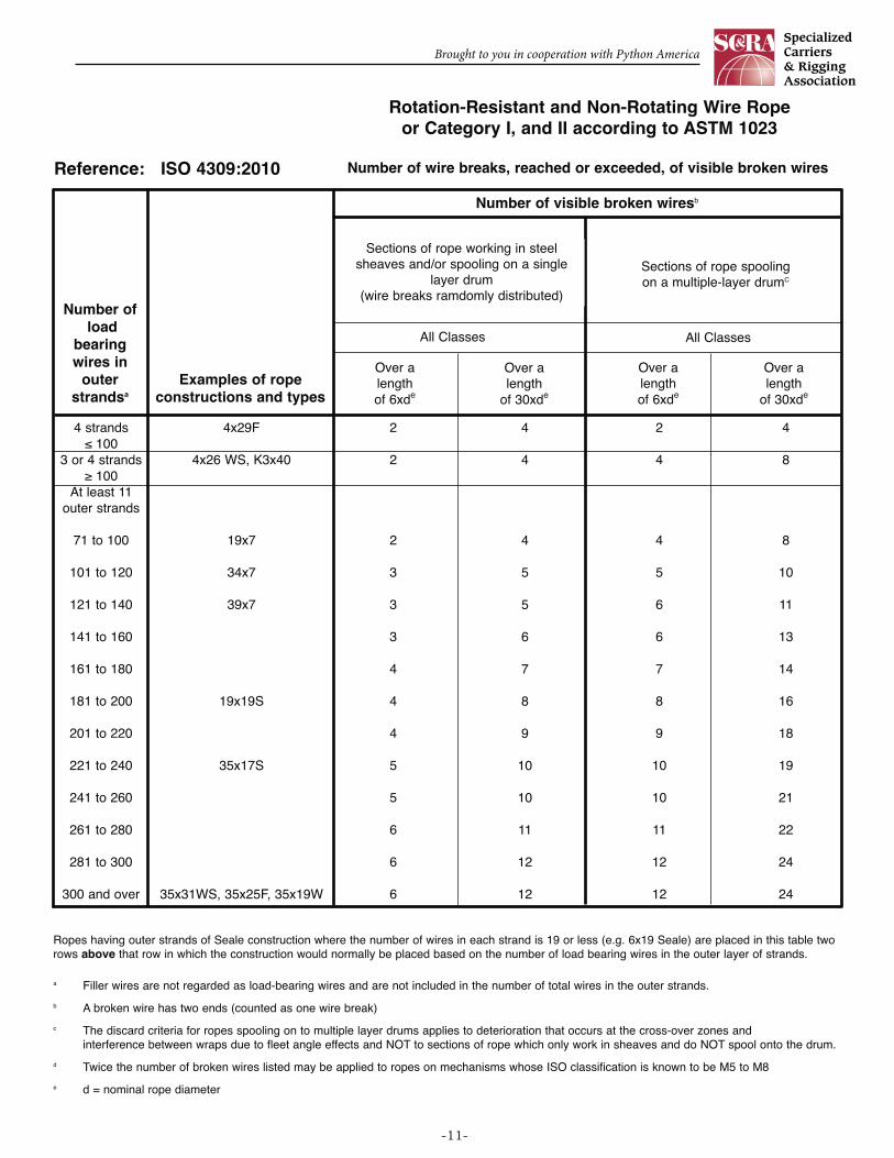
Reference: ISO 4309:2010
2
3
4
5
6
6
7
8
9
10
10
11
12
0.04n
4
6
8
10
11
13
14
16
18
19
21
22
24
0.08n
1
2
2
2
3
3
4
4
4
5
5
6
6
0.02n
2
3
4
5
6
6
7
8
9
10
10
11
12
0.04n
4
6
8
10
11
13
14
16
18
19
21
22
24
0.08n
8
12
16
19
22
26
29
32
38
38
42
45
48
0.16n
Sections of rope working in steel sheaves and/orspooling on a single layer drum
(wire breaks ramdomly distributed)
Classes M1 to M4 or class unknownd
Regular Lay Langs Lay
Over alengthof 6xde
Over alength
of 30xde
Over alengthof 6xde
Over alengthof 6xde
Over alength
of 30xde
Over alength
of 30xde
Regular and Langs Lay
All Classes
Sections of rope spoolingon a multiple-layer drumC
Number of wire breaks, reached or exceeded, of visible broken wires
Ropes having outer strands of Seale construction where the number of wires in each strand is 19 or less (e.g. 6x19 Seale) are placed in this table tworows above that row in which the construction would normally be placed based on the number of load bearing wires in the outer layer of strands.
a Filler wires are not regarded as load-bearing wires and are not included in the number of total wires in the outer strands.
b A broken wire has two ends (counted as one wire break)
c The discard criteria for ropes spooling on to multiple layer drums applies to deterioration that occurs at the cross-over zones and interference between wraps due to fleet angle effects and NOT to sections of rope which only work in sheaves and do NOT spool onto the drum.
d Twice the number of broken wires listed may be applied to ropes on mechanisms whose ISO classification is known to be M5 to M8
e d = nominal rope diameter
Regular single-layer and parallel type (e.g. DoPar®) Wire Rope
Brought to you in cooperation with Python America
-11-
Number ofload
bearingwires in
outerstrandsa
Examples of ropeconstructions and types
4 strands≤ 100
3 or 4 strands≥ 100
At least 11outer strands
71 to 100
101 to 120
121 to 140
141 to 160
161 to 180
181 to 200
201 to 220
221 to 240
241 to 260
261 to 280
281 to 300
300 and over
4x29F
4x26 WS, K3x40
19x7
34x7
39x7
19x19S
35x17S
35x31WS, 35x25F, 35x19W
Number of visible broken wiresb
Reference: ISO 4309:2010
2
2
2
3
3
3
4
4
4
5
5
6
6
6
4
4
4
5
5
6
7
8
9
10
10
11
12
12
2
4
4
5
6
6
7
8
9
10
10
11
12
12
4
8
8
10
11
13
14
16
18
19
21
22
24
24
Sections of rope working in steelsheaves and/or spooling on a single
layer drum(wire breaks ramdomly distributed)
All Classes
Over alengthof 6xde
Over alengthof 6xde
Over alength
of 30xde
Over alength
of 30xde
All Classes
Sections of rope spoolingon a multiple-layer drumC
Number of wire breaks, reached or exceeded, of visible broken wires
Ropes having outer strands of Seale construction where the number of wires in each strand is 19 or less (e.g. 6x19 Seale) are placed in this table tworows above that row in which the construction would normally be placed based on the number of load bearing wires in the outer layer of strands.
a Filler wires are not regarded as load-bearing wires and are not included in the number of total wires in the outer strands.
b A broken wire has two ends (counted as one wire break)
c The discard criteria for ropes spooling on to multiple layer drums applies to deterioration that occurs at the cross-over zones and interference between wraps due to fleet angle effects and NOT to sections of rope which only work in sheaves and do NOT spool onto the drum.
d Twice the number of broken wires listed may be applied to ropes on mechanisms whose ISO classification is known to be M5 to M8
e d = nominal rope diameter
Rotation-Resistant and Non-Rotating Wire Ropeor Category I, and II according to ASTM 1023
Brought to you in cooperation with Python America
-12-
Inspection of Wire Rope
Worn and abraided wires
Wear, due to friction on sheaves, rollers, drums, etc.,eventually causes outer wire abrasion.
Before any inspection is made, determine what type of wirerope you have in service. Many of today’s wire ropes are‘compacted’, ‘calibrated, or ‘die formed’. This manufacturingprocess purposely flattens the outer wires and for aninexperienced inspector these ropes may appear to be alreadyabraded when indeed they are brand new. If you are in doubtabout what type of rope you are about to inspect, have a look at asection of the rope which was not subjected to any abrasive work;e.g. like the safety wraps on the drum or a section just behind theend connection.
The round outer wires of standard wire rope will become flat onthe outside due to friction when in contact with drums, sheaves, orother abrasive matter like sand or gravel. This is part of normalservice deterioration and in most crane installations relatively evenabrasion will occur. The rope must be replaced, however, if thiswear exceeds 1/3 of the diameter of the wire.
It is good practice to compare a section of the rope whichwas NOT subjected to any bending work (e.g. the safetywraps, or a short section behind the end fitting) to the ropesection to be inspected.
The same applies when evaluating any possible reduced ropediameter during service. (See next column)
As already discussed on page -5- ‘Measuring the ropediameter’ and on page -6- ‘Break-In-Period’ shortly afterinstallation the wire rope diameter will slightly decrease. This isnormal and is caused by the adjustment of all rope elements whenloaded the first time. To evaluate the diameter reduction, you haveto measure the rope when new, and you also have to measure therope after the break in period at a specified load. This gives you agood indication of the magnitude of the initial diameter reduction inyour specific application. The diameter reading you took after thebreak in period should now become your ‘gauge’. Do not comparethe rope diameter you are about to take with the ‘catalogue’diameter. It may give you a false indication, since wire rope mayhave a plus tolerance of up to 4% to 5% over the ‘catalogue’diameter.
If you detect a further diameter reduction when measuring therope under the same load condition as after the break in period, itis often due to excessive abrasion of the outside wires, loss ofcore support, internal or external corrosion, inner wire failures,and/or inner wire abrasion. However, there will always be a normalcontinuous small decrease in diameter throughout the rope’sservice life.
Core deterioration, when it occurs, is revealed by a morerapid reduction in diameter, and when observed, it is time forremoval.
Deciding whether or not a rope is safe is not always a simplematter. A number of different but interrelated conditions must beevaluated. It would be dangerously unwise for an inspector todeclare a rope ‘safe’ for continued service simply because itsdiameter had not reached a certain minimum diameter if, at thesame time, other observations led to a different conclusion.
Because the removal criteria are much varied for different ropeconstructions and types of cores, a table of minimum diametershas been deliberately omitted from this publication.
(See: Core Wire Breaks page -11-)
Reduction in wire rope diameter
When the surface wires areworn by 1/3 or more of theirdiameter the rope must bereplaced.
Abrasion caused bydragging the rope over asharp object (steel corner,sharp plate, abrasive surfaceetc.)
Peening and subsequentwire break caused by highfleet angle and ropevibration.
Rope abrasion caused bynormal operating conditionon a high cycle crane. Ropemust be retired.
Take measurement of rope diameter AFTER the Break In Period.
Brought to you in cooperation with Python America
-13-
Inspection of Wire RopeRope Stretch
Constructional StretchAll ropes will stretch to varying degrees when loads are initially
applied. This stretch is known as the ‘constructional stretch’ (seealso: page -12- Run-In Period)This stretch occurs in three phases:
1) Initial or constructional stretch during the early period (Run-In) of rope service, caused by the rope adjusting to the operatingconditions.
2) Following the run-in period there there is a extended period-the longest part of the ropes’s service life- during which a slightincrease in stretch takes place over an extended time. This resultsfrom normal wear, fatigue etc. On a graph this portion wouldalmost be a horizontal straight line inclined slightly upward from itsinitial level.
3) Thereafter, the stretch occurs at a quicker rate. This meansthat the rope has reached the point of rapid degradation; a resultof prolonged subjection to abrasive wear, fatigue, and innerundetected wire breaks, etc. This second upturn of the curve is awarning indicating that the rope should be removed to avoidsudden catastrophic rope failures.
Elastic Stretch / Elastic LimitElastic stretch of wire rope occurs as soon as a load is applied.
When the load is released the rope returns to it’s initial length,hence the term ‘elastic’ stretch. This stretch is caused by theelastic deformation of the steel itself (the individual steel wires)and also by the lay of the rope which could be compared toresemble a coil spring. With other words, the longer the lay lengthof a rope becomes, the less elastic stretch it will develop. Elasticstretch in a wire rope is a desired feature. The ability of a rope tostretch under load means that the rope is capable to absorbenergy; the term here is ‘energy absorption capability’.
In many instances it is not easy to clearly distinguish between(the remains of) constructional stretch and elastic stretch as theymay occur together especially when the rope is new.
The values for Elastic Stretch are dependent on ropeconstruction, lay length and type, steel material, tensile strength ofwires etc. An approximation is o.25% to o.6% at WLL (or liftingcapacity). The E-module varies similarly from about 11 Million to16 Million lbs/inch2. For exact values please contact us for furtherinformation.
Elastic stretch turns into a ‘permanent’ stretch when the ropeis loaded beyond 55%-60% of it’s breaking strength (or beyond2-1/2 to 3 times its WLL). At that point the steel material elongatesand deforms permanently and renders the rope inoperable as theindividual wires will have lost much of their mechanical propertiesto withstand material fatigue.
Units of Rope Life
Un
its
of
Str
etch Nominal Life Stretch Ap
pro
ach
ing
Fai
lure
Co
nst
ruct
ion
al (
Init
ial)
Str
etch
The most difficult to detect wire rope deterioration. Core wirebreaks are more likely to appear in 6 & 8-strand and 19x7/19x19ropes, rather than in multi-strand plastic coated core wire rope. Wehave had examples where 8x36 and19x7 ropes broke showing noexternally visible removal criteria, yetthe core was completely broken topieces. Once the core breaks, theresultant sudden shock load on theouter strands may cause the rope tofail in a catastrophic, unpredictablemanner.
Core wire breaks in plastic coatedcore ropes are not likely to appear due
to the cushioning effect of the plastic layer. To inspect the core ofa 6- or 8-strand wire rope, the rope must be completely unloaded.
Carefully insert a spike through one or two strands and turn thespike with the rope lay. If the core is heavilylubricated you need good lighting to see brokenwires ! You may also wish to use a air gun toblow excessive lubricant off the core, but besure to re-lube the core after your inspection.
As with any rotation resistant or non-rotatingrope we recommend to leave such internalinspections to the expert as such inspectionscan permanently damage the rope.
Core Wire Breaks
Example of a typical elongation curve for a14 mm non-rotating wire rope.
Brought to you in cooperation with Python America
-14-
Inspection of Wire Rope
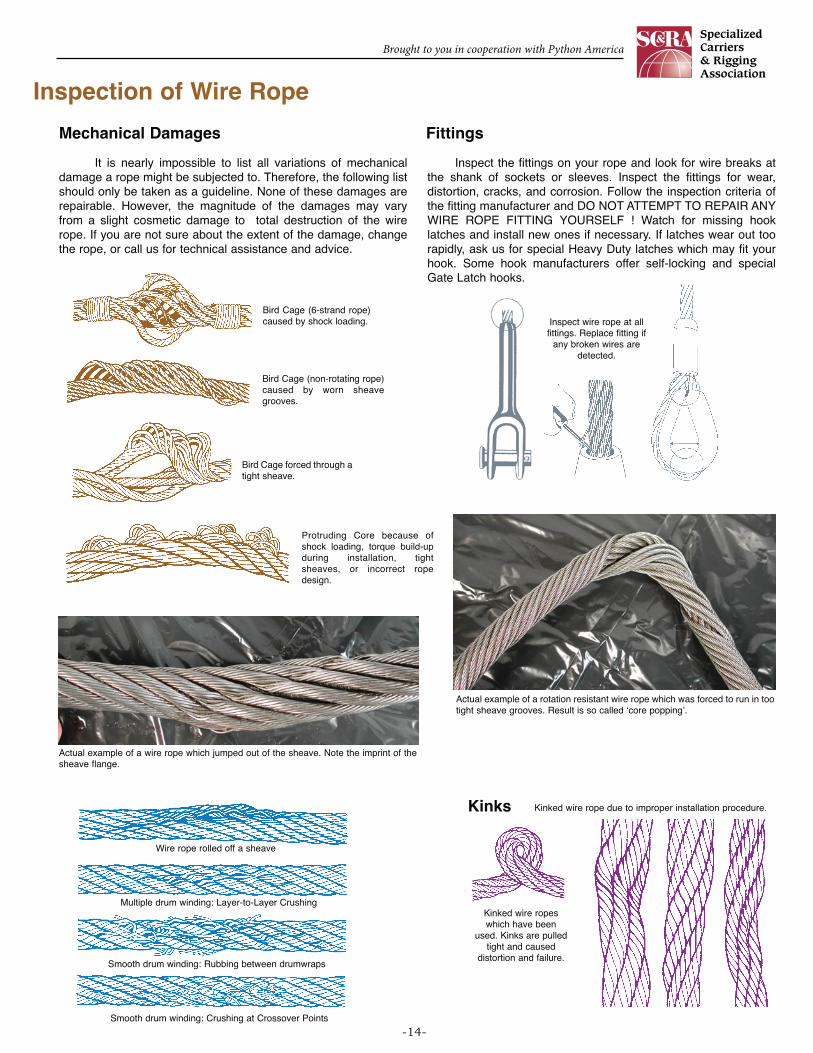
Mechanical Damages Fittings
It is nearly impossible to list all variations of mechanicaldamage a rope might be subjected to. Therefore, the following listshould only be taken as a guideline. None of these damages arerepairable. However, the magnitude of the damages may varyfrom a slight cosmetic damage to total destruction of the wirerope. If you are not sure about the extent of the damage, changethe rope, or call us for technical assistance and advice.
Inspect the fittings on your rope and look for wire breaks atthe shank of sockets or sleeves. Inspect the fittings for wear,distortion, cracks, and corrosion. Follow the inspection criteria ofthe fitting manufacturer and DO NOT ATTEMPT TO REPAIR ANYWIRE ROPE FITTING YOURSELF ! Watch for missing hooklatches and install new ones if necessary. If latches wear out toorapidly, ask us for special Heavy Duty latches which may fit yourhook. Some hook manufacturers offer self-locking and specialGate Latch hooks.
Inspect wire rope at allfittings. Replace fitting if
any broken wires aredetected.
Bird Cage (6-strand rope)caused by shock loading.
Bird Cage (non-rotating rope)caused by worn sheavegrooves.
Bird Cage forced through atight sheave.
Protruding Core because ofshock loading, torque build-upduring installation, tightsheaves, or incorrect ropedesign.
Wire rope rolled off a sheave
Smooth drum winding: Rubbing between drumwraps
Multiple drum winding: Layer-to-Layer Crushing
Smooth drum winding: Crushing at Crossover Points
Kinked wire rope due to improper installation procedure.
Kinked wire ropeswhich have been
used. Kinks are pulledtight and caused
distortion and failure.
Kinks
Actual example of a wire rope which jumped out of the sheave. Note the imprint of thesheave flange.
Actual example of a rotation resistant wire rope which was forced to run in tootight sheave grooves. Result is so called ‘core popping’.
Brought to you in cooperation with Python America
-15-
Inspection of Sheaves and Drums
Inspection Dimension of the Groove RadiusProper maintenance of the equipment on which the ropes
operate has an important bearing on rope life. Worn grooves,poor alignment of sheaves and worn parts resulting in shockloads and excessive vibration will have a deteriorating effect.
Sheaves should be checked periodically for wear in thegrooves which may cause pinching, abrasion, and bird-caging ofthe rope. If the groove shows signs of rope imprints the sheavemust be replaced or re-machined and re-hardened. The sameshould be done on drums showing similar effect.
Poor alignment of sheaves will result in rope wear and wearon the sheave flange. This should be corrected immediately.
Excessive wear in the sheave bearings can cause ropefatigue from vibration.
Large fleet angles will cause severe abrasion of the rope as itwinds onto the drum. Furthermore, the rope will roll into thesheave groove introducing torque and twist which may causehigh stranding and bird-cages.
The very first item to be checked when examining sheavesand drums, is the condition of the grooves. To check size,contour and amount of wear, a groove gauge is used.
Two types of groove gauges are in general use and it isimportant to note which of these is being used. The two differ intheir percentage over the Nominal Rope Diameter.
For new or remachined grooves, and for inspection of fitnessfor new ropes, the groove gauge should be 1% over themaximum allowable Plus Tolerance of the new rope; alternately,the sheave groove must measure 1% over the Actual RopeDiameter intended to be installed.
Many groove gauges on the market are so called ‘No-Go’gauges and are made with Nominal plus 1/2 of permissible ropePlus Tolerance. If you use these gauges be sure that the existingrope is SMALLER than this gauge. A rope operating in an evenslightly undersized groove, deteriorates faster and may developbird-cages.
Properly matchedrope & sheave
groove
Sheave groove toosmall
Sheave groove isundercut
New rope will getdamaged beyond
repair.
A sheave corrugated by therope’s ‘print’. This sheave will
damage the rope.
Sheave measured with ‘No-Go’gauge having only 1/2 the ropeoversize tolerance. New ropehaving full 5% oversize tolerancemay not fit. Sheave must bereplaced.
Same sheave measured withgauge having the full oversizetolerance of the rope. New ropewould get pinched and developsdamages like ‘Bird-Cages’ or‘High-Stranding’.
Check flanges for wear
Check sheavegrooves for wear
Check bearings forwobble, lubrication& ease of rotation
Correctly + 5% sized sheave gauges available from us.