45
1 Chapter 6 Paper Study: Data Center Networking
| Date post: | 10-Feb-2018 |
| Category: |
Documents |
| Upload: | hoangquynh |
| View: | 213 times |
| Download: | 0 times |

1
Chapter 6
Paper Study: Data Center Networking

Data Center Networking Major theme: What are new networking issues posed by
large-scale data centers?
Network Architecture? Topology design? Addressing? Routing? Forwarding? Please do the required readings!
2
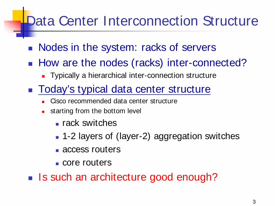
Data Center Interconnection Structure
Nodes in the system: racks of servers How are the nodes (racks) inter-connected?
Typically a hierarchical inter-connection structure
Today’s typical data center structure Cisco recommended data center structure starting from the bottom level
rack switches 1-2 layers of (layer-2) aggregation switches access routers core routers
Is such an architecture good enough?
3
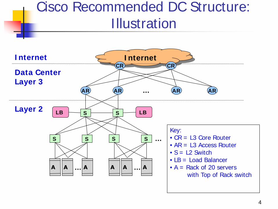
Cisco Recommended DC Structure: Illustration
4
Internet CR CR
AR AR AR AR …
S S LB LB
Data Center Layer 3
Internet
S S
…
S S
…
…
Layer 2
Key: • CR = L3 Core Router • AR = L3 Access Router • S = L2 Switch • LB = Load Balancer • A = Rack of 20 servers with Top of Rack switch

Data Center Design Requirements
Data centers typically run two types of applications outward facing (e.g., serving web pages to users) internal computations (e.g., MapReduce for web indexing)
Workloads often unpredictable: Multiple services run concurrently within a DC Demand for new services is unexpected
Failures of servers are the norm Recall that GFS, MapReduce, etc., resort to dynamic re-
assignment of chunkservers, jobs/tasks (worker servers) to deal with failures; data is often replicated across racks, …
“Traffic matrix” between servers are constantly changing
5
Data Center Costs
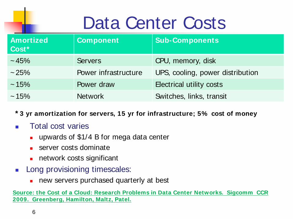
Total cost varies upwards of $1/4 B for mega data center server costs dominate network costs significant
Long provisioning timescales: new servers purchased quarterly at best
6
Amortized Cost*
Component Sub-Components
~45% Servers CPU, memory, disk
~25% Power infrastructure UPS, cooling, power distribution
~15% Power draw Electrical utility costs
~15% Network Switches, links, transit
*3 yr amortization for servers, 15 yr for infrastructure; 5% cost of money
Source: the Cost of a Cloud: Research Problems in Data Center Networks. Sigcomm CCR 2009. Greenberg, Hamilton, Maltz, Patel.
Overall Data Center Design Goal Agility – Any service, Any Server Turn the servers into a single large fungible pool
Let services “breathe” : dynamically expand and contract their footprint as needed this is done in terms of Google’s GFS (Google File System),
BigTable, MapReduce.
Benefits Increase service developer productivity Lower cost Achieve high performance and reliability
These are the three motivators for most data center infrastructure projects!
7
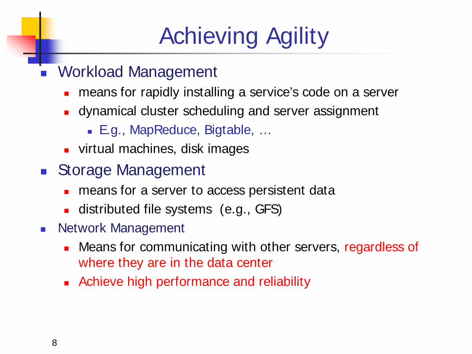
Achieving Agility Workload Management
means for rapidly installing a service’s code on a server dynamical cluster scheduling and server assignment
E.g., MapReduce, Bigtable, … virtual machines, disk images
Storage Management means for a server to access persistent data distributed file systems (e.g., GFS)
Network Management Means for communicating with other servers, regardless of
where they are in the data center Achieve high performance and reliability
8
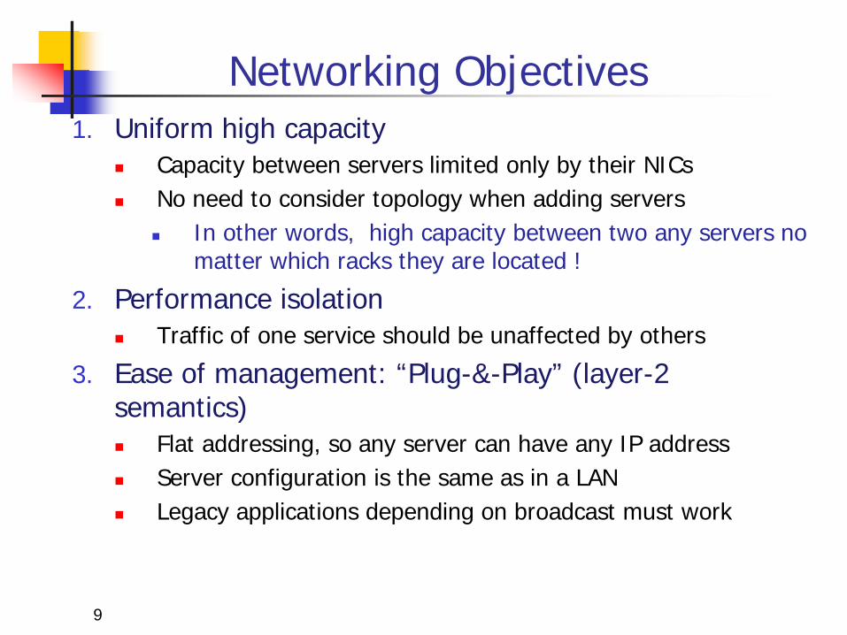
Networking Objectives 1. Uniform high capacity
Capacity between servers limited only by their NICs No need to consider topology when adding servers
In other words, high capacity between two any servers no matter which racks they are located !
2. Performance isolation Traffic of one service should be unaffected by others
3. Ease of management: “Plug-&-Play” (layer-2 semantics) Flat addressing, so any server can have any IP address Server configuration is the same as in a LAN Legacy applications depending on broadcast must work
9

Is Today’s DC Architecture Adequate?
10
Internet CR CR
AR AR AR AR …
S S LB LB
Data Center Layer 3
Internet
S S
…
S S
…
…
Layer 2 Key: • CR = L3 Core Router • AR = L3 Access Router • S = L2 Switch • LB = Load Balancer • A = Top of Rack switch
• Uniform high capacity? • Performance isolation? typically via VLANs
• Agility in terms of dynamically adding or shrinking servers?
• Agility in terms of adapting to failures, and to traffic dynamics?
• Ease of management?
• Hierarchical network; 1+1 redundancy • Equipment higher in the hierarchy handles more traffic
• more expensive, more efforts made at availability scale-up design • Servers connect via 1 Gbps link to Top-of-Rack switches • Other links are mix of 1G, 10G; fiber, copper

Papers Study
A Scalable, Commodity Data Center Network Architecture a new Fat-tree “inter-connection” structure (topology) to increases
“bi-section” bandwidth
needs “new” addressing, forwarding/routing
VL2: A Scalable and Flexible Data Center Network consolidate layer-2/layer-3 into a “virtual layer 2” separating “naming” and “addressing”, also deal with
dynamic load-balancing issues
Optional Materials PortLand: A Scalable Fault-Tolerant Layer 2 Data Center Network
Fabric BCube: A High-Performance, Server-centric Network Architecture
for Modular Data Centers 11
A Scalable, Commodity Data Center Network Architecture
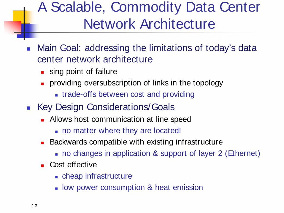
Main Goal: addressing the limitations of today’s data center network architecture sing point of failure providing oversubscription of links in the topology
trade-offs between cost and providing
Key Design Considerations/Goals Allows host communication at line speed
no matter where they are located! Backwards compatible with existing infrastructure
no changes in application & support of layer 2 (Ethernet) Cost effective
cheap infrastructure low power consumption & heat emission
12
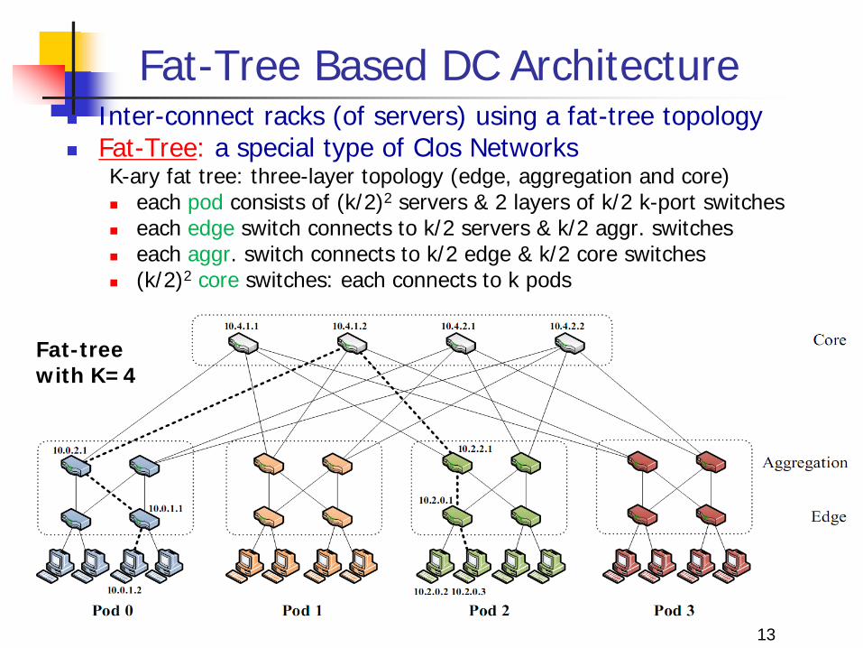
Fat-Tree Based DC Architecture Inter-connect racks (of servers) using a fat-tree topology Fat-Tree: a special type of Clos Networks
K-ary fat tree: three-layer topology (edge, aggregation and core) each pod consists of (k/2)2 servers & 2 layers of k/2 k-port switches each edge switch connects to k/2 servers & k/2 aggr. switches each aggr. switch connects to k/2 edge & k/2 core switches (k/2)2 core switches: each connects to k pods
Fat-tree with K=4
13

Fat-Tree Based Topology … Why Fat-Tree?
Fat tree has identical bandwidth at any bisections Each layer has the same aggregated bandwidth
Can be built using cheap devices with uniform capacity Each port supports same speed as end host All devices can transmit at line speed if packets are distributed uniform
along available paths
Great scalability: k-port switch supports k3/4 servers
Fat tree network with K = 3 supporting 54 hosts
14
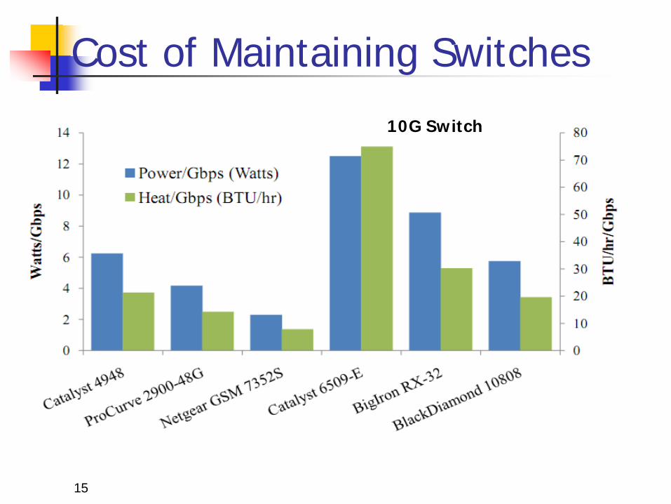
Cost of Maintaining Switches
15
10G Switch
Fat-tree Topology is Great, But …
Does using fat-tree topology to inter-connect racks of servers in itself sufficient?
What routing protocols should we run on these switches?
Layer 2 switch algorithm: data plane flooding! Layer 3 IP routing:
shortest path IP routing will typically use only one path despite the path diversity in the topology
if using equal-cost multi-path routing at each switch independently and blindly, packet re-ordering may occur; further load may not necessarily be well-balanced
Aside: control plane flooding!
16
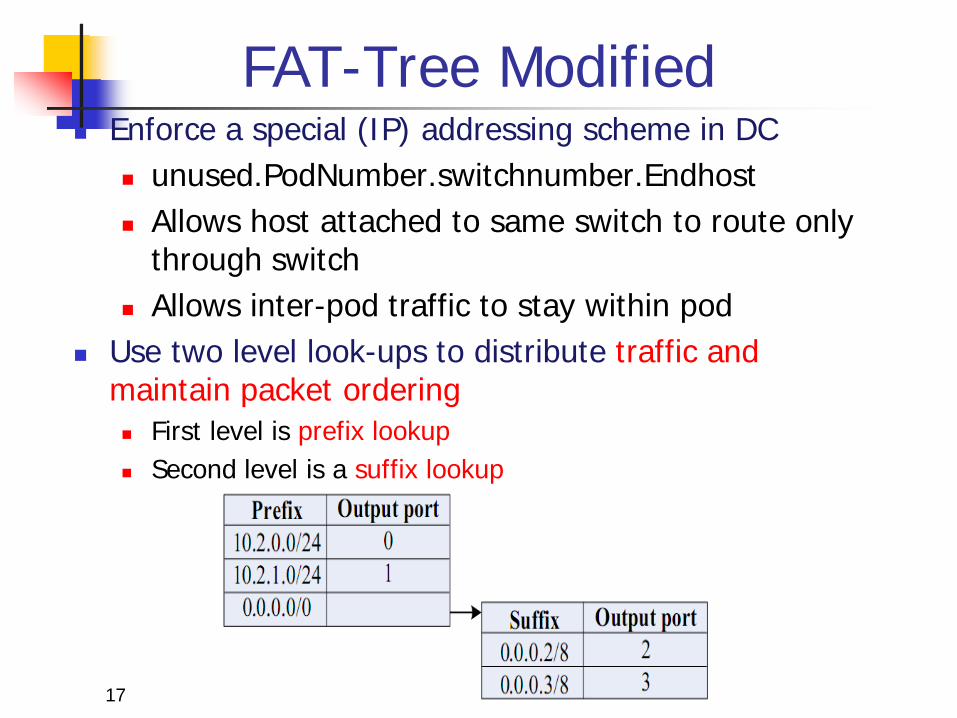
FAT-Tree Modified Enforce a special (IP) addressing scheme in DC
unused.PodNumber.switchnumber.Endhost Allows host attached to same switch to route only
through switch Allows inter-pod traffic to stay within pod
Use two level look-ups to distribute traffic and maintain packet ordering First level is prefix lookup Second level is a suffix lookup
17
More on Fat-Tree DC Architecture Diffusion Optimizations Flow classification
Eliminates local congestion Assign to traffic to ports on a per-flow basis
instead of a per-host basis Flow scheduling
Eliminates global congestion Prevent long lived flows from sharing the same
links Assign long lived flows to different links
What are potential drawbacks of this architecture?
18
VL2: A Scalable and Flexible Data Center Network
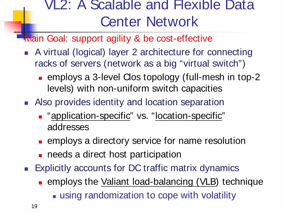
Main Goal: support agility & be cost-effective A virtual (logical) layer 2 architecture for connecting
racks of servers (network as a big “virtual switch”) employs a 3-level Clos topology (full-mesh in top-2
levels) with non-uniform switch capacities Also provides identity and location separation
“application-specific” vs. “location-specific” addresses
employs a directory service for name resolution needs a direct host participation
Explicitly accounts for DC traffic matrix dynamics employs the Valiant load-balancing (VLB) technique
using randomization to cope with volatility
19
Specific Objectives and Solutions
20
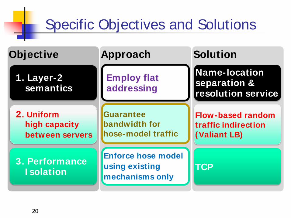
Solution Approach Objective
2. Uniform high capacity between servers
Enforce hose model using existing mechanisms only
Employ flat addressing
1. Layer-2 semantics
3. Performance Isolation
Guarantee bandwidth for hose-model traffic
Flow-based random traffic indirection (Valiant LB)
Name-location separation & resolution service
TCP
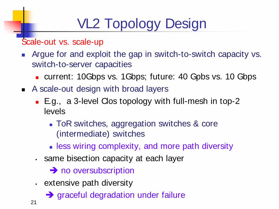
VL2 Topology Design Scale-out vs. scale-up Argue for and exploit the gap in switch-to-switch capacity vs.
switch-to-server capacities current: 10Gbps vs. 1Gbps; future: 40 Gpbs vs. 10 Gbps
A scale-out design with broad layers E.g., a 3-level Clos topology with full-mesh in top-2
levels ToR switches, aggregation switches & core
(intermediate) switches less wiring complexity, and more path diversity
• same bisection capacity at each layer no oversubscription
• extensive path diversity graceful degradation under failure
21
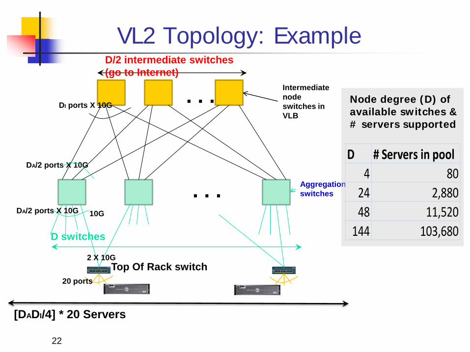
VL2 Topology: Example
10G
DA/2 ports X 10G
Aggregation switches
. . .
. . .
D switches
D/2 intermediate switches (go to Internet)
Intermediate node switches in VLB
DI ports X 10G
Top Of Rack switch
[DADI/4] * 20 Servers
20 ports
Node degree (D) of available switches & # servers supported
D # Servers in pool4 80
24 2,88048 11,520
144 103,680
22
DA/2 ports X 10G
2 X 10G
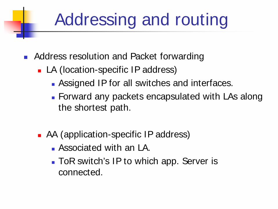
Addressing and routing
Address resolution and Packet forwarding LA (location-specific IP address)
Assigned IP for all switches and interfaces. Forward any packets encapsulated with LAs along
the shortest path.
AA (application-specific IP address) Associated with an LA. ToR switch’s IP to which app. Server is
connected.
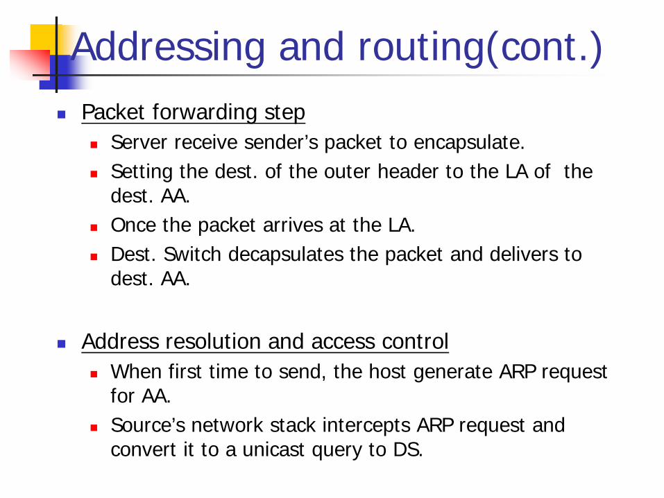
Addressing and routing(cont.) Packet forwarding step
Server receive sender’s packet to encapsulate. Setting the dest. of the outer header to the LA of the
dest. AA. Once the packet arrives at the LA. Dest. Switch decapsulates the packet and delivers to
dest. AA.
Address resolution and access control When first time to send, the host generate ARP request
for AA. Source’s network stack intercepts ARP request and
convert it to a unicast query to DS.

Address Resolution and Packet Forwarding

26
Addressing and Routing: Name-Location Separation
payload ToR3
. . . . . .
y x
Servers use flat names
Switches run link-state routing and maintain only switch-level topology
Cope with host churns with very little overhead
y z payload ToR4 z
ToR2 ToR4 ToR1 ToR3
y, z payload ToR3 z
. . .
Directory Service …
x ToR2 y ToR3 z ToR4 …
Lookup & Response
… x ToR2 y ToR3 z ToR3 …
• Allows to use low-cost switches • Protects network and hosts from host-state churn • Obviates host and switch reconfiguration
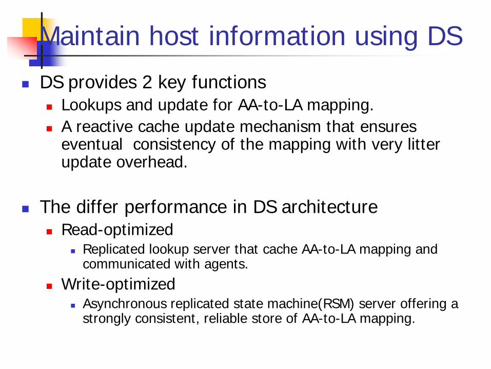
Maintain host information using DS
DS provides 2 key functions Lookups and update for AA-to-LA mapping. A reactive cache update mechanism that ensures
eventual consistency of the mapping with very litter update overhead.
The differ performance in DS architecture Read-optimized
Replicated lookup server that cache AA-to-LA mapping and communicated with agents.
Write-optimized Asynchronous replicated state machine(RSM) server offering a
strongly consistent, reliable store of AA-to-LA mapping.

Directory System Replicated state machine (RSM): Offer a strongly consistent, reliable store of AA-to-LA mapping
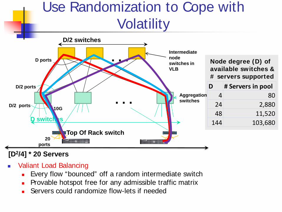
Use Randomization to Cope with Volatility
Valiant Load Balancing Every flow “bounced” off a random intermediate switch Provable hotspot free for any admissible traffic matrix Servers could randomize flow-lets if needed
Node degree (D) of available switches & # servers supported
D # Servers in pool4 80
24 2,88048 11,520
144 103,680
10G D/2 ports
D/2 ports
. . .
. . . D switches
D/2 switches
Intermediate node switches in VLB
D ports
Top Of Rack switch
[D2/4] * 20 Servers
20 ports
Aggregation switches

VL2 Summary VL2 achieves agility at scale via
1. L2 semantics 2. Uniform high capacity between servers 3. Performance isolation between services
31
Lessons • Randomization can tame volatility • Add functionality where you have
control • There’s no need to wait!
Additional Case Studies
Optional Material
PortLand: A Scalable Fault-Tolerant Layer 2 Data Center Network Fabric Main idea: new “hierarchical” addressing scheme
to facilitate dynamic and fault-tolerant routing/forwarding
32
PortLand: A Scalable Fault-Tolerant Layer 2 Data Center Network Fabric
In a nutshell: PortLand is a single “logical layer 2” data center
network fabric that scales to millions of endpoints PortLand internally separates host identity from host
location uses IP address as host identifier introduces “Pseudo MAC” (PMAC) addresses
internally to encode endpoint location PortLand runs on commodity switch hardware with
unmodified hosts
33
PortLand Requirements
Any VM may migrate to any physical machine. Migrating VMs should not have to change their IP addresses as doing so will break pre-existing TCP connections and application-level state.
An administrator should not need to configure any switch before deployment.
Any end host should be able to efficiently communicate with any other end host in the data center along any of the available physical communication paths.
There should be no forwarding loops. Failures will be common at scale, so failure detection should be
rapid and efficient. Existing unicast and multicast sessions should proceed unaffected to the extent allowed by underlying physical connectivity.
34
Design Goals for Network Fabric Support for Agility! Easy configuration and management: plug-&-play Fault tolerance, routing and addressing: scalability Commodity switch hardware: small switch state Virtualization support: seamless VM migration
What are the limitations of current layer-2 and layer-3? layer-2 (Ethernet w/ flat-addressing) vs. layer-3 (IP w/
prefix-based addressing): plug-&-play? scalability? small switch state? seamless VM migration?
35

PortLand Solution Assuming: a Fat-tree network topology for DC Introduce “pseudo MAC addresses” to balance the pros and
cons of flat- vs. topology-dependent addressing PMACs are “topology-dependent,” hierarchical addresses
But used only as “host locators,” not “host identities” IP addresses used as “host identities” (for compatibility w/ apps)
Pros: small switch state & Seamless VM migration “eliminate” flooding in both data & control planes
But requires a IP-to-PMAC mapping and name resolution a location directory service
And location discovery protocol & fabric manager for support of “plug-&-play”
36
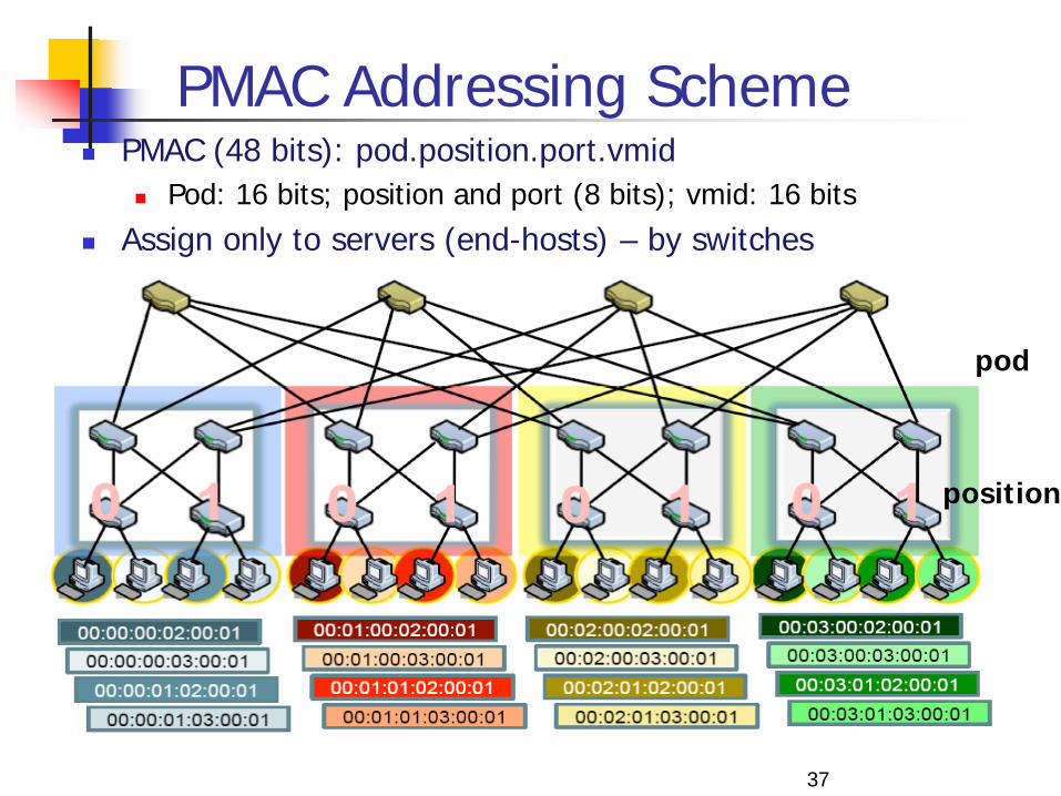
PMAC Addressing Scheme PMAC (48 bits): pod.position.port.vmid
Pod: 16 bits; position and port (8 bits); vmid: 16 bits Assign only to servers (end-hosts) – by switches
37
pod
position
Location Discovery Protocol
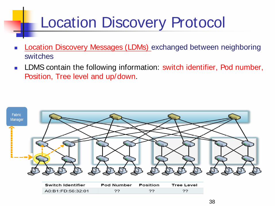
Location Discovery Messages (LDMs) exchanged between neighboring switches
LDMS contain the following information: switch identifier, Pod number, Position, Tree level and up/down.
38
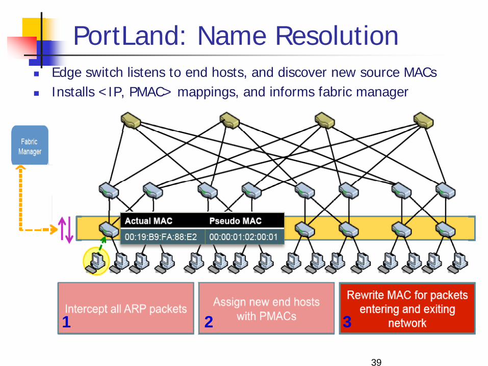
PortLand: Name Resolution Edge switch listens to end hosts, and discover new source MACs Installs <IP, PMAC> mappings, and informs fabric manager
39
1 2 3

PortLand: Name Resolution … 1. Edge switch intercepts ARP messages from end hosts 2. Send request to fabric manager, which replies with
PMAC
40

PortLand: Fabric Manager fabric manager: logically centralized, multi-homed
server maintains topology and <IP,PMAC> mappings in “soft
state”
41

Loop-free Forwarding and Fault-Tolerant Routing
Switches build forwarding tables based on their position edge, aggregation and core switches
Use strict “up-down semantics” to ensure loop-free forwarding Load-balancing: use any ECMP path via flow hashing
to ensure packet ordering Fault-tolerant routing:
Mostly concerned with detecting failures Fabric manager maintains logical fault matrix with
per-link connectivity info; inform affected switches Affected switches re-compute forwarding tables
42
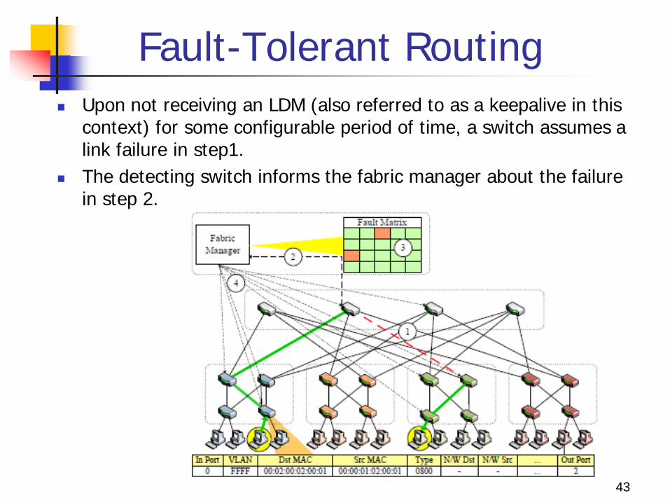
Fault-Tolerant Routing Upon not receiving an LDM (also referred to as a keepalive in this
context) for some configurable period of time, a switch assumes a link failure in step1.
The detecting switch informs the fabric manager about the failure in step 2.
43

Fault-Tolerant Routing
The fabric manager maintains a logical fault matrix with per-link connectivity information for the entire topology and updates it with the new information in step 3.
In step 4, the fabric manager informs all affected switches of the failure, which then individually recalculate their forwarding tables based on the new version of the topology.
44
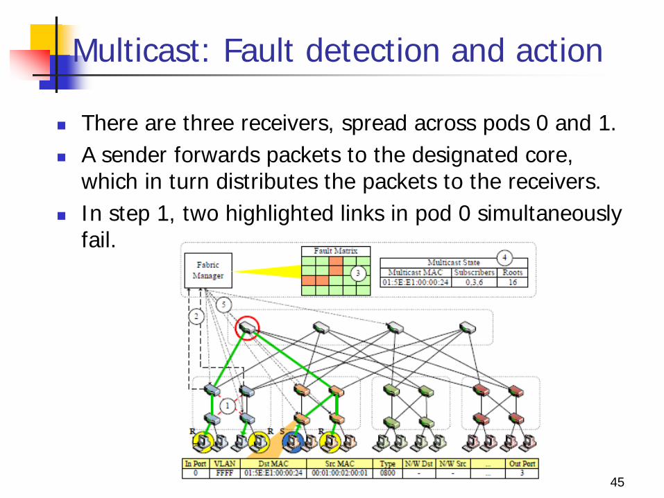
Multicast: Fault detection and action
There are three receivers, spread across pods 0 and 1. A sender forwards packets to the designated core,
which in turn distributes the packets to the receivers. In step 1, two highlighted links in pod 0 simultaneously
fail.
45

Multicast: Fault detection and action
Two aggregation switches detect the failure in step 2 and notify the fabric manager, which in turn updates its fault matrix in step 3.
The fabric manager calculates forwarding entries for all affected multicast groups in step 4.
46

![WWW Piramide - IntroducciónPD] Publicaciones... · WWW। Piramide ।।।।।।।.com WWW। ।।।।।।। ।।।।।।।।।।। ।।।।।।।.com](https://static.documents.pub/doc/80x56/5e0b08b231a4536209097ef2/www-piramide-introduccin-pd-publicaciones-wwwa-piramide-aaaaaaacom.jpg)


