1 Wireless Biosensing Using Silver-Enhancement Based Self-assembled Antennas in Passive Radio Frequency Identification (RFID) Tags Mingquan Yuan, Student Member, IEEE, Premjeet Chahal, Member, IEEE, Evangelyn C. Alocilja, Member, IEEE and Shantanu Chakrabartty, Senior Member, IEEE Abstract—In this paper, we present a silver-enhancement technique for self-assembling radio-frequency (RF) antennas and demonstrate its application for remote biosensing. When target analytes or pathogens are present in a sample the silver- enhancement process self-assembles a chain of micro-monopole antennas. As the size of the silver-enhanced particles grows, the chain of micro-antenna segments bridge together to complete a macro-antenna structure. The change in the electrical impedance across the bridge modulates the reflection properties of the antenna at a desired frequency. In this paper we have used this principle to model, optimize and design a ratiometric mode 915 MHz radio-frequency identification (RFID) based biosensor which uses relative received signal strength indicator (RSSI) to measure and detect different concentration levels of target analytes. We have validated the proof-of-concept for detecting two types of analytes: (a) IgG in rabbit serum at concentration levels ranging from 20 ng to 60 ng; and (b) moisture in a sample at volumes ranging from 5μl to 40μl. A significant advantage of the proposed biosensor is that the concentration level of target analytes or pathogens can be remotely interrogated in a concealed, packaged or in a bio-hazardous environment, where direct electrical or optical measurement is considered to be impractical. Index Terms—Passive RFID; Wireless Detection; Micro- Antennas; Dipole; Self-assembly; Biosensor; Humidity Sensor; Silver Enhancement I. I NTRODUCTION R ADIO-frequency identification (RFID) technology is at- tractive for biosensing applications because the sensors can be wirelessly interrogated when operating in a concealed, packaged or in a bio-hazardous environment where direct measurement is not considered to be practical. The scenario is specifically relevant for monitoring a product supply-chain (shown in Fig. 1) where the use of passive RFID tagging technology is becoming more wide-spread [1], [2]. Integrating biosensing capabilities with passive RFID tags ensures that the sensors are low-cost and because these sensor-tags operate without batteries, their shelf-life is comparable to the products being monitored. To date most RFID based biosensors operate This work is supported by a research grant from the National Science Foundation (CCF:1117186) and by a research grant from the Midland Research Institute for Value Chain Creation (MRIVCC). Mingquan Yuan, Premjeet Chahal and Shantanu Chakrabartty are with the Department of Electrical and Computer Engineering, Michigan State University, East Lans- ing, MI, 48824 USA (e-mail: [email protected]; [email protected]; [email protected]). Evangelyn C. Alocilja is with the Department of Biosystems and Agricul- tural Engineering, Michigan State University, East Lansing, MI, 48824 USA (e-mail: [email protected]). L (c) RFID writer/reader Sensor RFID tag Fig. 1. Illustration of the RFID tag integrated inside a package and being interrogated by an RFID reader (bluetooth reader shown). Data from the RFID reader can be retrieved by a laptop or using a smartphone via a bluetooth connection. on a unifying principle which is to modulate the electrical impedance seen at the terminals of an RFID antenna [3]. The modulation then changes the RF reflection properties of the tag which can then be measured remotely using an RFID reader. For example, RFID based humidity sensors reported in [4], [5], [6] integrate a layer of water absorbing material on the surface of the tag. Moisture absorption on the layer changes the dielectric constant of the layer which in turn changes the effective impedance of the RFID antenna and hence its reflection properties [4], [5], [6]. The principle has also been used for detecting bio-analytes and bio-markers. For instance, in [7] a molecular imprinted polymer (MIP) based passive RFID sensor was reported for detecting histamines in spoiled fish. Another example is a split-ring resonator (SRR) based RFID biosensor which was reported in [8], [9] and used for detecting prostrate-specific antigen (PSA), a prostrate cancer bio-marker. In [10], we had proposed an alternative concept for imple- menting a RFID based biosensor. Based on the presence of different concentration levels of target analytes, the structure of the antenna changes leading to the change in the antenna’s reflection properties. At the core of this method is a silver- enhancement process that self-assembles parts of the RFID antenna in the presence of target analytes. Compared to conventional approaches, the proposed method has several advantages: (a) the approach can be easily integrated with existing commercial off-the-shelf RFID tags because it is
Transcript
1
Wireless Biosensing Using Silver-EnhancementBased Self-assembled Antennas in Passive Radio
Frequency Identification (RFID) TagsMingquan Yuan, Student Member, IEEE, Premjeet Chahal, Member, IEEE, Evangelyn C. Alocilja, Member, IEEE
and Shantanu Chakrabartty, Senior Member, IEEE
Abstract—In this paper, we present a silver-enhancementtechnique for self-assembling radio-frequency (RF) antennasand demonstrate its application for remote biosensing. Whentarget analytes or pathogens are present in a sample the silver-enhancement process self-assembles a chain of micro-monopoleantennas. As the size of the silver-enhanced particles grows, thechain of micro-antenna segments bridge together to complete amacro-antenna structure. The change in the electrical impedanceacross the bridge modulates the reflection properties of theantenna at a desired frequency. In this paper we have usedthis principle to model, optimize and design a ratiometric mode915 MHz radio-frequency identification (RFID) based biosensorwhich uses relative received signal strength indicator (RSSI)to measure and detect different concentration levels of targetanalytes. We have validated the proof-of-concept for detectingtwo types of analytes: (a) IgG in rabbit serum at concentrationlevels ranging from 20 ng to 60 ng; and (b) moisture in a sampleat volumes ranging from 5µl to 40µl. A significant advantageof the proposed biosensor is that the concentration level oftarget analytes or pathogens can be remotely interrogated in aconcealed, packaged or in a bio-hazardous environment, wheredirect electrical or optical measurement is considered to beimpractical.
RADIO-frequency identification (RFID) technology is at-tractive for biosensing applications because the sensors
can be wirelessly interrogated when operating in a concealed,packaged or in a bio-hazardous environment where directmeasurement is not considered to be practical. The scenariois specifically relevant for monitoring a product supply-chain(shown in Fig. 1) where the use of passive RFID taggingtechnology is becoming more wide-spread [1], [2]. Integratingbiosensing capabilities with passive RFID tags ensures thatthe sensors are low-cost and because these sensor-tags operatewithout batteries, their shelf-life is comparable to the productsbeing monitored. To date most RFID based biosensors operate
This work is supported by a research grant from the National ScienceFoundation (CCF:1117186) and by a research grant from the MidlandResearch Institute for Value Chain Creation (MRIVCC). Mingquan Yuan,Premjeet Chahal and Shantanu Chakrabartty are with the Department ofElectrical and Computer Engineering, Michigan State University, East Lans-ing, MI, 48824 USA (e-mail: [email protected]; [email protected];[email protected]).
Evangelyn C. Alocilja is with the Department of Biosystems and Agricul-tural Engineering, Michigan State University, East Lansing, MI, 48824 USA(e-mail: [email protected]).
L
(c)RFID writer/readerIC
Sensor RFID tag
Fig. 1. Illustration of the RFID tag integrated inside a package and beinginterrogated by an RFID reader (bluetooth reader shown). Data from the RFIDreader can be retrieved by a laptop or using a smartphone via a bluetoothconnection.
on a unifying principle which is to modulate the electricalimpedance seen at the terminals of an RFID antenna [3]. Themodulation then changes the RF reflection properties of the tagwhich can then be measured remotely using an RFID reader.For example, RFID based humidity sensors reported in [4],[5], [6] integrate a layer of water absorbing material on thesurface of the tag. Moisture absorption on the layer changesthe dielectric constant of the layer which in turn changesthe effective impedance of the RFID antenna and hence itsreflection properties [4], [5], [6]. The principle has also beenused for detecting bio-analytes and bio-markers. For instance,in [7] a molecular imprinted polymer (MIP) based passiveRFID sensor was reported for detecting histamines in spoiledfish. Another example is a split-ring resonator (SRR) basedRFID biosensor which was reported in [8], [9] and used fordetecting prostrate-specific antigen (PSA), a prostrate cancerbio-marker.
In [10], we had proposed an alternative concept for imple-menting a RFID based biosensor. Based on the presence ofdifferent concentration levels of target analytes, the structureof the antenna changes leading to the change in the antenna’sreflection properties. At the core of this method is a silver-enhancement process that self-assembles parts of the RFIDantenna in the presence of target analytes. Compared toconventional approaches, the proposed method has severaladvantages: (a) the approach can be easily integrated withexisting commercial off-the-shelf RFID tags because it is
2
generally easier to modify the large surface area spanned bythe antenna rather than manipulating the microscale silicon diehosting the RFID electronics; (b) because of the large surfacearea, different parts of the antenna could be functionalized withdifferent types of detection probes, implying that the proposedapproach could be easily extended for multi-analyte detection;(c) because the effective length of the antenna could be directlymodified, the proposed approach could be used to obtain aquantitative estimate of the analyte concentration without theneed for additional peripheral measurement system; and (d)the silver-enhancement process is materially compatible withconventional silver-ink based printable RFID tags and can beextended to flexible substrates. In this paper, we extend theconcept proposed in [10] to characterize and optimize theparameters of the sensor using multi-physics finite-elementsimulations. Also, in this paper we have explored a newapplication of the self-assembly based sensing that is fordetection of moisture/humidity.
The paper is organized as follows: In section II we brieflydescribe the process of silver enhancement followed by sec-tion III which describes the finite-element model used forsimulating the RFID biosensor. Section III also describes themodel and simulation of a ratiometric RFID configurationused for compensation and calibration purposes. Section IVdescribes two proof-of-concept applications of the proposedtechnique: detection of IgG in rabbit serum and detection ofmoisture in a sample. Section V presents a discussion of theproposed method highlighting its limitations and challenges.Section VI then concludes the paper with discussions aboutthe future research directions.
II. OPERATING PRINCIPLE OF SILVER ENHANCEMENT
The proposed RFID biosensor is based on the physics ofsilver-enhancement [11], [12] and is illustrated in Fig. 2. Goldnanoparticles conjugated with target bioreceptors (for exampleantibodies shown in Fig. 2) or embedded inside a matrix,are first immobilized between two conductive electrodes asshown in Fig. 2(a) and the corresponding micrograph. Notethat the gold nanoparticles are not large enough to electricallybridge the separated electrodes. This state corresponds to anopen-circuit state where practically no DC current flows be-tween the two electrodes. When a silver-enhancement solutioncomprising of Ag ions (I) and hydroquinone (photographicdeveloping solution) is applied between the electrodes, goldnanoparticles are exposed to the silver-enhancement solution.In the presence of reducing agent hydroquinone, the silverions reduce into metallic silver on the surface of the goldnanoparticles. During this reaction, the gold nanoparticle actsas a catalyst and facilitates further reduction of silver ions.As more silver ions are reduced, a chain of gold nanopar-ticle cored silver micromonopole antennas self-assembles inbetween the electrodes as shown in Fig. 2(b). As a result,noticeable current can flow between the two electrodes due todisplacement currents or due to electron hopping and tunnel-ing. This constitutes a sub-threshold state where the conductivebridge between the electrodes still has not completely formed.With the progression of time and in the presence of more
analytes, more silver ions gets reduced and in the limit thechain of micromonopole antennas gets completely bridgedas shown in Fig. 2(c). Electrons can now freely flow whena potential difference is applied across the two electrodes.In [11], [12] we have experimentally demonstrated that thechange in conductance after the silver enhancement processis monotonic with respect to the concentration of the targetanalyte. Details of the experimental results can be foundin [11], [12] and have been omitted for the sake of brevity.Therefore, the starting point of our simulation would be todetermine the effect of antenna’s reflection properties due tochange in conductance because of silver-enhancement.
(a) open circuit
silver
aIgG
(b) subthreshold (c) short circuit
e- e-gold nanoparticle
IV + V -
5um
electrodes
Fig. 2. Illustration of three stages of the silver-enhancement process: (a)isolation mode: before the silver enhancement solution applied, the electrodesare electrically isolated; (b) subthreshold mode: during the silver enhancementprocess, the silver ions get reduced to form metallic silver; (c) above-thresholdmode: the path between the two electrodes are electrically bridged and moresilver ions are reduced.
III. ANALYSIS AND MODELING
Since the interrogation of the RFID biosensor relies ondetecting changes in the reflection properties of the RFIDantenna, Friis transmission equation can be used to understandthe relationship between the power received at the sensor’santenna Pr and the power of the interrogation signal Pt. Therelationship can be expressed as:
Pr
Pt= GtGr
(λ
4πL
)2
(1)
where Gt and Gr are the respective gains of the readerand sensor antennas, λ is the wavelength of the RF signal,and L is the distance between the reader and the tag. Thepower transfered to the tag electronics, Pic, and the reflectedpower received at the reader, Preader, can be expressed usingequations (2) and (3) as:
Pic = Pr(1 − Γ1) (2)
Preader = PicGtGr
(λ
4πL
)2
(1 − Γ2) (3)
where Γ1 and Γ2 are input and output reflection coefficients,respectively. For the sake of simplicity we will assume thatthe two reflection coefficients are equal:
Fig. 3. (a) Finite-element model of resistance loaded ALN-9640 RFID tag, the gap formed is for resistance loading; (b) Simulated S11 at 915MHz fordifferent conductance values of the gap material and gap sizes; (c) Simulated S11 as a function of frequency for different conductances of the gap materialand for the gap length of 0.2mm; (Insert) Radiation patterns corresponding to an impedance matched (in red) tag and corresponding to a tag loaded with 100S/m conductance gap material (in blue).
which leads to the reflected power received at the reader as:
Preader = Pt
[GtGr
(λ
4πL
)2]2
(1 − Γ)2 (5)
Equation (5) shows that the received power Preader can beused to infer the magnitude of the reflection coefficient. Toeliminate the non-relevant terms in equation (5), a control tagis used which is co-located with the sensor tag. Thus, the termsPt, Gt, Gr, λ and L are common to both the tags. Thus, theratio of the power received from the sensor tag and the powerreceived from the control tag can be expressed as:
P sreader
P creader
=(1 − Γs)
2
(1 − Γc)2(6)
where P sreader, Γs, P c
reader and Γc denote the received powerand reflection coefficients for the sensor tag and the controltag, respectively.
A. Finite-element Modeling and Ratiometric Readout
Equation (6) only represents a generic first-order relation-ship between the reflected power and a tag antenna. Toobtain results more specific to a particular type of antennaand tag configuration, we resort to finite-element simulationsof the antenna’s radiated power. For this study we chosean antenna configuration corresponding to commercial ALN-9640 915MHz RFID tag [13], which is shown in Fig. 3(a).
(a) sends ping (b) both tags respond (c) detect collision
(d) back off algorithm (f) read control tag(e) read sensor tag
Fig. 4. Using multi-access capability of Gen-2 UHF RFID protocol forratiometric RSSI measurement.
The antenna is constructed using Aluminum and a gap is intro-duced in the antenna (marked by yellow in Fig. 3(a)) where thesilver-enhancement based sensor could be integrated. For thisstudy we have assumed that the sensor can be modeled usinga material whose conductivity changes based on the degreeof silver-enhancement as described previously. For the sakeof symmetry, the silver-enhancement was integrated on bothsides of the antenna and the RF reflection properties of thestructure was modeled using HFSS. The reflection coefficientΓ in equation (6) can then be estimated using the antenna’sscattering parameter S11 [14]. Fig. 3(b) shows the relationshipbetween the simulated S11 at 915MHz and different valuesof conductances for the material in the gap. The resultsshow that lower value of reflection coefficients (S11) can bereached when the material has a conductance equal to that
4
(a) Located on the same plane (b) Stacked vertically
(c) Oriented 90o with respect to each other
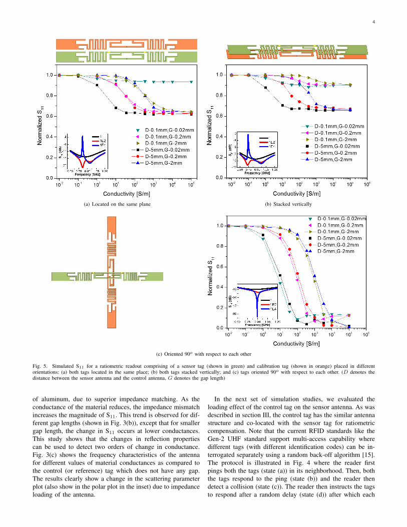
Fig. 5. Simulated S11 for a ratiometric readout comprising of a sensor tag (shown in green) and calibration tag (shown in orange) placed in differentorientations: (a) both tags located in the same place; (b) both tags stacked vertically; and (c) tags oriented 90o with respect to each other. (D denotes thedistance between the sensor antenna and the control antenna, G denotes the gap length)
of aluminum, due to superior impedance matching. As theconductance of the material reduces, the impedance mismatchincreases the magnitude of S11. This trend is observed for dif-ferent gap lengths (shown in Fig. 3(b)), except that for smallergap length, the change in S11 occurs at lower conductances.This study shows that the changes in reflection propertiescan be used to detect two orders of change in conductance.Fig. 3(c) shows the frequency characteristics of the antennafor different values of material conductances as compared tothe control (or reference) tag which does not have any gap.The results clearly show a change in the scattering parameterplot (also show in the polar plot in the inset) due to impedanceloading of the antenna.
In the next set of simulation studies, we evaluated theloading effect of the control tag on the sensor antenna. As wasdescribed in section III, the control tag has the similar antennastructure and co-located with the sensor tag for ratiometriccompensation. Note that the current RFID standards like theGen-2 UHF standard support multi-access capability wheredifferent tags (with different identification codes) can be in-terrogated separately using a random back-off algorithm [15].The protocol is illustrated in Fig. 4 where the reader firstpings both the tags (state (a)) in its neighborhood. Then, boththe tags respond to the ping (state (b)) and the reader thendetect a collision (state (c)). The reader then instructs the tagsto respond after a random delay (state (d)) after which each
5
TapePrimary Antibody Target
Gold nanoparticle conjugated secondary antibody
Gap
(I)
(II)
(III)
Nitrocellulose
Metallic silver Antenna part
(IV)
(a)
TapePrimary Antibody Target
Gold nanoparticle conjugated secondary antibody
Gap
(a)
(b)
(c)Nitrocellulose
Metallic silver Antenna part
(d)
(b)
Reservoir
Gold nanoparticle conjugated IgG
(V)
(VI)
(b)(VII)
Silver
enhancement powder
Nitrocellulose membrane
TapeWater
Antenna part
Metallic silver
(VIII)
(b)
Fig. 6. Working principle of the silver-enhancement process for dipole antenna based biosensor and humidity sensor. (a) IgG detection: (I) top view of thebiosensor structure with one gap on each side covered with NC membrane; (II) cross-sectional view of the antenna gap with gold nanoparticle conjugatedanti-rabbit IgG forming a sandwich structure before silver-enhancement; (III) cross-sectional view after the gap is bridged using silver-enhancement; (IV)top view of 915MHz COTS dipole antenna based RFID humidity sensor structure. (b) Moisture detection: (V) top view of the biosensor structure withone gap on each side; (VI) cross-sectional view of the antenna gap with gold nanoparticle conjugated anti-rabbit IgG immobilized on NC membrane beforesilver-enhancement; (VII) cross-sectional view after the gap is bridged after DI water is applied to facilitate the silver-enhancement; (VIII) top view of 915MHzCOTS dipole antenna based RFID humidity sensor structure.
of the tags respond separately (state (e) and (f)). Thus, eventhough the tags are co-located, a reader can measure the RSSIfor each of the tags. For our simulations we have assumedthat only one of the tags respond at a time and the effectof the non-responsive tag is to affect the antenna loadingcharacteristics. Fig. 5 shows the simulation results for threeconfigurations of tag placements: (a) when both the tags arelocated on the same plane; (b) when the tags are verticallystacked; and (c) when the tags are oriented 90o with respectto each other. For all the simulations the distance betweenthe two antennas D and the gap length G were varied alongwith the conductance of the gap material. In cases (a) and(b) the coupling effect can be clearly seen in the S11 plot(inset) which show multiple resonant peaks, peak broadeningand a shift in the resonance frequencies. However, if theS11 is measured at 915MHz, the response is still monotonicwith respect to the conductance of the gap material. However,from a practical point of view configuration (a) and (b) mightbe problematic because for both cases the reader sensitivitycould be significantly reduced due to the degradation in thequality factor. For the configuration shown in (c), both the S11
response and the conductance characteristics are minimallyaffected. Thus, this configuration will be used for our proof-of-concept experiments.
IV. PROOF-OF-CONCEPT APPLICATIONS
We apply the proposed RFID sensing for two proof-of-concept applications: (a) detection of IgG in a sample; and (b)detection of moisture in a sample. The functionalization andmodification of the antenna gap is shown in Fig. 6 for both theapplications. For all the experiments, commercial passive EPC
Gen 2 UHF RFID tags manufactured by Alien Technologieshave been used.
A. IgG Detection: Principle, Materials and Methods
The working principle of the proposed RFID biosensorfor IgG detection is shown in Fig. 6(a). The tag antennawith a gap on each side is first glued to a plastic backingmaterial as shown in Fig. 6 (I). The gap is then coveredby a nitrocellulose (NC) membrane with the NC side facingthe aluminum antenna. Then target specific antibodies (aIgG)are immobilized on the surface of NC membrane. When asolution of the conjugates of the target and the secondaryantibody (in this case IgG and gold nanoparticle conjugatedanti-IgG (aIgG-AuNP)), IgG-aIgG-AuNP, is applied from theside of the NC membrane, the conjugates move to the surfaceof NC membrane due to capillary forces. In this regard, theprocess of conjugation and hybridization with the immobilizedantibodies is similar to that of a lateral-flow immunoassay [16]and the details about fabrication of the application pad andthe conjugate pad can be found in [17] and has been omittedhere for the sake of brevity. Due to antibody-antigen hy-bridization, a sandwich structure (aIgG-IgG-aIgG-AuNP) isformed and is shown in Fig. 6 (II). The excess unbondedsandwich conjugates are washed away from the NC membranedue to capillary force. The remaining aIgG-IgG-aIgG-AuNPconjugates are now detected using the silver-enhancement ofthe RFID antenna as described in section II.
Silver Enhancement Kit for Proteins and Nucleic Acids wasobtained from Ted Pella (Redding, CA, USA). Anti-RabbitIgG (whole molecule) conjugated with gold nanoparticlesproduced in goat (product number: G7402), anti-rabbit IgG
6
antibody produced in goat (product number: R2004) and IgGfrom rabbit serum (product number: I5006) were purchasedfrom Sigma-Aldrich (St Louis, MO, USA). Glutaraldehydeand Methanol were also obtained from Sigma- Aldrich (StLouis, MO, USA). Nitrocellulose (NC) membrane with flowrate of 135 sec/4cm was purchased from Millipore (Billerica,MA, USA). Deionized (DI) water used in the experiment wasobtained through Millipore water purification systems (Bil-lerica, MA, USA). Passive 915 MHz UHF RFID tags (ALN9640) were purchased from atlasRFID store (Birmingham,AL, USA). Scanfob Ultra-BB2 Wireless GEN2 UHF RFIDReader/Writer (Cedar Park, TX, USA) was used as detector inthe experiment. All experiments were carried out in a certifiedBiological Safety Level II laboratory.
The NC membrane was cut into small pieces, washed withDI water three times and dried for 30min. Then NC membraneis immersed in 10% (v/v) methanol for 45min and left dryfor 30min in air. After that, it is washed with 0.5% (v/v)glutaraldehyde solution and dried in air for 60min. Anti-IgG (R2004, primary antibody used in this experiment) isthen applied on NC membrane, which is sealed with parafilmin petri dish and incubated at 37◦C for 1 hour. Then NCmembrane is washed with DI water for 3 times and air driedfor 1h. Until now, the pretreatment of NC membrane is doneand ready to use.
Each side of the dipole antenna is cut to form a small gap.The dipole antenna is attached to the plastic substrate withdouble-sided tape. The NC membranes are then attached tothe surface of antenna with tape to cover each of the gaps.Then the conjugates of the target and secondary antibody (IgG-aIgG-AuNP) are applied on two gaps of antenna from the sideedges of the NC membranes. The reagent volumes used fordifferent antennas are 2µl, 4µl and 6µl, separately. Then, thedipole antennas are sealed with parafilm in the petri dish andincubated at 37◦C for 1 hour. The NC membranes are thenwashed 3 times with DI water and dried in the drier box.Silver-enhancement solution is prepared by mixing the initiatorand enhancer with volume ratio of 1:1. The NC membrane isthen immersed in silver-enhancement solution. To facilitate thesilver ions reduction, the silver-enhancement reaction is takenplace in 37◦C for 25min instead of room temperature. Afterthe silver-enhancement process, the NC membrane is washedwith DI water, dried and ready to be read by 915MHz ScanfobUltra-BB2 reader. Photos of the NC membrane surface aretaken with optical microscope (magnification of 500×) beforeand after silver-enhancement, shown in Fig. 7 (a) and (b),respectively. Before silver-enhancement, the surface of NCmembrane is only functionalized with the sandwich structuredconjugates (aIgG-IgG-aIgG-AuNP). Due to the size of goldnanoparticle is around 10nm, Fig. 7 (a) is mainly showingthe texture of the porous NC membrane itself. Different fromthis, Fig. 7 (b) is the surface view of aIgG-IgG-aIgG-AuNPfunctionalized NC membrane with silver-enhancement. Silver-enhancement process resulted metallic silver is deposited onthe surface of gold nanoparticles, enlarges the size of thenanoparticles into micrometer scale and results in the forma-tion of micro-antennas, which can be visually observed fromthe micro-photograph.
50um 50um
(a) (b)
Fig. 7. (a) NC membrane with aIgG-IgG-aIgG-AuNP functionalized beforesilver-enhancement (microphotograph); (b) NC membrane with aIgG-IgG-aIgG-AuNP functionalized after silver-enhancement (microphotograph).
B. Humidity Detection: Principle, Materials and Methods
The working principle of the RFID biosensor for humiditydetection is shown in Fig. 6(b). The principle is similar tothat of IgG detection and is based on the principle of silver-enhancement technique that can electrically bridge the splitRFID dipole antenna parts. However, the difference is thatthe silver-enhancement solution is applied in a dried form.Silver-enhancement kit was purchased from the vendor intwo separate forms (named as initiator and enhancer) andin liquid forms. The initiator and enhancer were dried andcrystallized separately in a dark environment. The procedure ofthe NC membrane treatment is similar to that of the proceduredescribed in the previous section. The NC membrane is alsocut into small pieces, washed with DI water three times anddried. It is then treated 10% (v/v) methanol for 45 min anddried for 30min. 0.5% (v/v) glutaraldehyde solution is usedto treat NC membrane, which is dried in air for 60 min. Thedifference from the procedure described for IgG detection isthat the gold nanoparticle conjugated anti-IgG (aIgG-AuNP) isnow immobilized on the NC membrane. aIgG-AuNP is appliedon NC membrane, which is sealed with parafilm in petri dishand incubated at 37◦C for 1 hour. Then it is washed with DIwater and dried for 1h.
Each side of the RFID dipole antenna (ALN-9640) iscut to form a small electrically insulated gap of dimensions0.4mm. The pretreated NC membranes are glued to the surfaceof antenna with tape. Two gaps of the dipole antenna arecovered by aIgG-AuNP immobilized NC membranes withnitrocellulose side facing the aluminum antenna. On the otherside of the RFID dipole antenna (plastic substrate side of theRFID antenna), a reservoir is affixed right on each gap withJ-B KwikWeld super glue, shown in Fig. 6 (V) and (VI).The reservoir here works as a container for the storage ofsilver-enhancement powder. After 4 hours’ super glue curingtime, the powder of silver enhancer (with ratio of initiator andenhancer of 1:1) is filled into the reservoir. The basic humiditysensor’s operation principle is similar to that of the biosensordescribed previously in this paper. When the humidity sensor isexposed to the water, the dry silver-enhancement powder getsdissolved and liquid silver-enhancement solution is regener-ated. As the silver-enhancement solution diffuses through theNC membrane silver ions are reduced into metallic silver onthe surface of gold nanoparticles. Similar to the self-assemblyprinciple described in section II, the reduced silver electricallybridges the antenna gap, as shown in Fig. 6 (VII).
7
V. MEASURED RESULTS
The complete schematic RFID based detection and measure-ment system is shown in Fig. 1. The system includes a 915MHz RFID writer/reader (Scanfob Ultra-BB2) which can in-terfaces with a laptop with cable or smart phone via bluetoothconnection for data analysis and display. The formation ofmicro-antennas in the gap can effectively bridge the two splitdipole antenna parts, which modulates the length of the dipoleantenna. As a result, different concentration of target analytescan be quantified based on the RFID interrogation distanceunder the same power emitted from the RFID writer/reader.An unmodified 915 MHz dipole antenna (same structure asour experimental implemented biosensor dipole but withoutany treatment) is interrogated by the RFID writer/reader asa calibration source. Note that this procedure of using anCOTS RFID reader is more practical for use in the field ratherthan probing the feed-points of the antenna and measuring itseffective S11. Also, the antenna is loaded by the tag’s chipset(which is an active element) and therefore using a networkanalyzer to measure S11 may not serve as an accurate indicatorof the power reflected by the tag. The farthest distances of thebiosensor and the calibration tag that can be interrogated byRFID reader are denoted as L1 and L2, respectively. All themeasured maximum detection distances of the biosensor (L1)are normalized with regards to that of the calibration dipoleantenna (L2).
A. IgG Detection Results
Fig. 8(a) shows the normalized detection length of dipoleantenna biosensor when different amount of IgG-aIgG-AuNPconjugates (ranging from 0µl to 6µl) are used. For thebiosensor when no IgG-aIgG-AuNP conjugates are applied(equivalent to the situation that no target analyte is detected),the normalized detection length is only around 12% to thatof the calibration dipole antenna. When each side of theantenna is cut to form a small gap, the input impedance ofit is changed, which causes the RFID tag operating withlower efficiency. Under the same power emitted from theRFID writer, it can only be sensed in a much shorter distancecompared to the original unmodified dipole antenna. For dipoleantenna with certain amount of IgG-aIgG-AuNP conjugatesapplied, both the controlled (without silver-enhancement) andthe experimental (with silver-enhancement) were run. Themeasured results are monotonic with respect to the differentvolumes of IgG-aIgG-AuNP conjugates applied, shown inFig. 8(a). In this proof-of-concept study, a minimum amountof target analytes which can be differentiated from the controlexperiment was 26.9ng. The signal-to-noise threshold levelspre-programmed on the COTS RFID reader determines thislower-limit of detection for this study. When the gap of thedipole antenna is completely electrically bridged by the micro-antennas, the RFID antenna’s reflection properties is mainlydetermined by the host dipole structure. The detection lengthof the biosensor gets saturated in the range between 64% to77% when a high target concentration (53.8ng in this paper)is applied. Even if more target conjugates are applied to thebiosensor, it will not improve the bridging quality (impedance
2ul IgG 4ul IgG 6ul IgG0
0.2
0.4
0.6
0.8
1
No
rmal
ized
det
ecti
on
dis
tan
ce
Only cut treatmentBefore silver enhancementAfter silver enhancement
(a)
5 10 15 20 25 30 35 400.1
0.15
0.2
0.25
0.3
0.35
0.4
0.45
0.5
Different volumes of DI water and oil applied (ul)
No
rmal
ized
det
ecti
on
dis
tan
ce
DI waterOilWithout DI water
(b)
Fig. 8. (a) Normalized maximum detection length of dipole antenna biosen-sors with regard to that of the calibration antenna when different volumes ofIgG are applied; (b)Normalized maximum detection length of dipole antennahumidity sensor with regard to that of the calibration antenna when differentvolumes of DI water and oil are applied.
matching) and also will not contribute to the increase ofdetection length. For this experiment the resolution of thebiosensor was measured to be 5.58×10⁻⁴ per ng rabbit IgGover a detection range of 4 µl.
B. Humidity Detection Results
Fig. 8(b) shows the normalized maximum detection rangewhen different volumes of DI water (ranging from 5µl to40µl) are applied. There is an obvious increase in the detectionlength when water is applied to the humidity sensor comparedto that without DI water applied. For the dipole antennawithout the presence of DI water, the maximum normalizeddetection length is around 12% to 15% with respect to thatof the calibration antenna. The minimum amount of DI waterapplied to the humidity sensor in this experiment is 5µl and thedetection range increased to 19.89% of that of the calibrationantenna which is nearly doubled compared with the detectionlength without DI water applied. It indicates that the gap
8
between the separated antenna parts starts to be bridged bythe silver-enhancement. The measured detection range showsa nearly monotonic relationship with respect to the volume ofDI water. The detection length of the humidity sensor stops tomonotonously increase when the volume of applied DI waterreaches 25µl and keeps stable at the value between 40% and45%. It is because silver-enhancement process has completelybridged the gaps of the dipole antenna and the responseof the RFID tag is mainly determined by the host dipolestructure. The resolution of the sensor for detecting moisturewas measured to be 1.76×10⁻³ per µl. Vegetable oil (withvolumes ranging from 5µl to 40µl) is applied to the humiditysensor as control experiment. Fig. 8(b) shows that normalizeddetection range does not vary much (at a value between 13%and 16%) when different volumes of vegetable oil is applied.The measurements show that the applied vegetable oil will notcontribute to the increase of the humidity sensor’s detectionlength since it cannot facilitate the silver deposition whichmodifies the input impedance of the RFID dipole antenna.
VI. CONCLUSIONS
In this article we presented a novel approach for de-signing RFID based biosensors which used self-assembly ofthe tag antenna using a silver-enhancement technique. Thesilver-enhancement approach self-assembles a chain of micro-antennas (gold nanoparticle cored silver shelled particles)based on target analytes. The growth of these micro-antennaschanges the input impedance of the RFID dipole antennawhich ultimately modifies the reflection properties of the RFIDtag. The change in reflection properties can be detected andmeasured using a COTS RFID reader. In this paper, we havealso proposed a ratiometric approach for robust measurementof the reflected signal strength. The optimal configuration usestwo co-located tags that are oriented 90o with respect to eachother and minimizes mutual antenna loading. The approachhas been applied and demonstrated for two proof-of-conceptapplications: (a) detection of IgG in a sample; and (b) detectionof humidity in a sample. The measured results show that theratiometric measurement can not only be used to detect targetanalytes but also to measure their concentration levels withina certain range. The challenge for the proposed sensor andwill form part of the future research is the integration ofsample acquisition interface (like microfluidics or lateral-flowstructures) with the product package being monitored. Thefuture work will also explore the end to end multi-physicssimulation of the proposed concept that combines the physicsof analyte-receptor interactions with the physics of silver-enhancement and the physics of antenna propagation.
REFERENCES
[1] S. Roy, V. Jandhyala, J. R. Smith, D. J. Wetherall, B. P. Otis,R. Chakraborty, M. Buettner, D. J. Yeager, Y.-C. Ko, and A. P. Sample,“Rfid: From supply chains to sensor nets,” Proceedings of the IEEE,vol. 98, no. 9, pp. 1583–1592, 2010.
[2] R. Angeles, “Rfid technologies: supply-chain applications and imple-mentation issues,” Information Systems Management, vol. 22, no. 1, pp.51–65, 2005.
[3] S. Capdevila, L. Jofre, J.-C. Bolomey, and J. Romeu, “Rfid multiprobeimpedance-based sensors,” Instrumentation and Measurement, IEEETransactions on, vol. 59, no. 12, pp. 3093–3101, 2010.
[4] K. Chang, Y.-H. Kim, Y.-J. Kim, and Y. J. Yoon, “Functional antennaintegrated with relative humidity sensor using synthesised polyimide forpassive rfid sensing,” Electronics letters, vol. 43, no. 5, pp. 259–260,2007.
[5] Y. Jia, M. Heiß, Q. Fu, and N. A. Gay, “A prototype rfid humiditysensor for built environment monitoring,” in Education Technology andTraining, 2008. and 2008 International Workshop on Geoscience andRemote Sensing. ETT and GRS 2008. International Workshop on, vol. 2.IEEE, 2008, pp. 496–499.
[6] J. Siden, X. Zeng, T. Unander, A. Koptyug, and H.-E. Nilsson, “Remotemoisture sensing utilizing ordinary rfid tags,” in Sensors, 2007 IEEE.IEEE, 2007, pp. 308–311.
[7] D. Croux, T. Vangerven, J. Broeders, J. Boutsen, M. Peeters,S. Duchateau, T. Cleij, W. Deferme, P. Wagner, R. Thoelen et al.,“Molecular imprinted polymer films on rfid tags: a first step towardsdisposable packaging sensors,” physica status solidi (a), vol. 210, no. 5,pp. 938–944, 2013.
[8] H.-J. Lee and J.-G. Yook, “Biosensing using split-ring resonators atmicrowave regime,” Applied Physics Letters, vol. 92, no. 25, pp.254 103–254 103, 2008.
[10] M. Yuan, E. C. Alocilja, and S. Chakrabartty, “A novel biosensor basedon silver-enhanced self-assembled radio-frequency antennas,” SensorsJournal, IEEE, vol. 14, no. 4, pp. 941–942, April 2014.
[11] Y. Liu, D. Zhang, E. C. Alocilja, and S. Chakrabartty, “Biomoleculesdetection using a silver-enhanced gold nanoparticle-based biochip,”Nanoscale Research Letters, vol. 5, no. 3, pp. 533–538, 2010.
[12] Y. Liu, M. Gu, E. C. Alocilja, and S. Chakrabartty, “Co-detection:Ultra-reliable nanoparticle-based electrical detection of biomoleculesin the presence of large background interference,” Biosensors andBioelectronics, vol. 26, no. 3, pp. 1087–1092, 2010.
[16] Y. Liu, S. Chakrabartty, and E. C. Alocilja, “Fundamental buildingblocks for molecular biowire based forward error-correcting biosensors,”Nanotechnology, vol. 18, no. 42, p. 424017, 2007.
[17] T. C. Tisone and B. OFarrell, Manufacturing the next generation ofhighly sensitive and reproducible lateral flow immunoassay. Springer,2009.
Mingquan Yuan (S’14) received the B.S. degree inelectronic science and technology from HuazhongUniversity of Science and Technology, Wuhan,China, in 2009, and the M.S. degree in electron-ics engineering and computer science from PekingUniversity, Beijing, China, in 2012.
He is currently working towards the Ph.D. degreeat Michigan State University (MSU), East Lansing,MI. His research interests include passive wirelesssensors, RFID, micro/nano fabrication.
9
Premjeet Chahal (M’03) received the B.S. andM.S. degrees in electrical engineering from IowaState University, Ames, and the Ph.D. degree inelectrical engineering from the Georgia Institute ofTechnology, Atlanta, in 1999.
He was a Senior Researcher with Raytheon, Dal-las, TX, from 1999 to 2006, and Abbott Laborato-ries, Abbott Park, IL, from 2006 to 2008. He devel-oped many new technologies for sensing, devices,packaging, and components at Abbott Laboratoriesand Raytheon. He joined the faculty at Michigan
State University, East Lansing, in 2009. He holds four U.S. patents and hasapplied for four others. His current research interests include terahertz tech-nology and their applications, millimeter-wave devices and circuits, chemicaland biological sensors, and electronics packaging.
Evangelyn C. Alocilja (M’87) received the B.S. de-gree in chemistry (cum laude) from Silliman Univer-sity, Dumaguete City, Philippines, in 1973, the M.S.degree in soil chemistry/plant physiology from theUniversity of Philippines, Quezon City, Philippines,in 1981, and the M.S. and Ph.D. degrees in systemsscience/electrical engineering from Michigan StateUniversity, East Lansing, MI, in 1983 and 1987,respectively.
She is currently an Associate Professor in theDepartment of Biosystems and Agricultural Engi-
neering and an Adjunct Professor in the Institute of International Health,Michigan State University. From 1987 to 1990, she was a Postdoctoral Fellowin Agricultural Engineering, Crop Science, and Electrical Engineering atMichigan State University. From 1991 to 1992, she was a Research Consultantat the International Rice Research Institute, Philippines. In 1992, she wasa Research Consultant with the Commonwealth Scientific and IndustrialResearch Organization, Australia. She is a Co-investigator of the NationalCenter for Food Protection and Defense, Department of Homeland SecurityCenter of Excellence. Her research interests include the development ofnanoparticle-based biosensors for homeland security, food and water safety,and health care.
Shantanu Chakrabartty (SM’99-M’04-S’09) re-ceived his B.Tech degree from Indian Institute ofTechnology, Delhi in 1996, M.S and Ph.D in Elec-trical Engineering from Johns Hopkins University,Baltimore, MD in 2002 and 2004 respectively. He iscurrently a professor in the department of computerscience and engineering at Washington Universityin St. Louis. From 2004-2015, he was an asso-ciate professor in the department of electrical andcomputer engineering at Michigan State University(MSU). From 1996-1999 he was with Qualcomm
Incorporated, San Diego and during 2002 he was a visiting researcher atThe University of Tokyo. Dr. Chakrabartty’s work covers different aspectsof analog computing, in particular non-volatile circuits, and his currentresearch interests include energy harvesting sensors and neuromorphic andhybrid circuits and systems. Dr. Chakrabartty was a Catalyst foundationfellow from 1999-2004 and is a recipient of National Science Foundation’sCAREER award, University Teacher-Scholar Award from MSU and the 2012Technology of the Year Award from MSU Technologies. Dr. Chakrabartty isa senior member of the IEEE and is currently serving as the associate editorfor IEEE Transactions of Biomedical Circuits and Systems, associate editorfor the Advances in Artificial Neural Systems journal and a review editor forFrontiers of Neuromorphic Engineering journal.