15
Wireless Bridge RS-232 USERS MANUAL R02

Wireless Bridge RS-232
USERS MANUAL
R02
RS-232 WIRELESS BRIDGE USER’S MANAUL REV. 02 2
Contents
Overview ....................................................................................................................................................... 3
Specifications ................................................................................................................................................ 3
Performance ............................................................................................................................................. 3
Power Requirements ................................................................................................................................ 4
Mechanical ................................................................................................................................................ 4
Pinout and Wiring ..................................................................................................................................... 5
Operation ...................................................................................................................................................... 6
Basic Operation ......................................................................................................................................... 6
LED Indication ....................................................................................................................................... 6
Data Formats and Baud Rates ............................................................................................................... 7
Common Configurations and Use Cases ....................................................................................................... 7
Radio Architectures ................................................................................................................................... 7
Point-to Point ........................................................................................................................................ 7
Point-to-Multipoint ............................................................................................................................... 8
Communicating with the Wireless Bridge ................................................................................................ 8
RS-232 Command reference table ...................................................................................................... 10
Changing the Baud Rate .......................................................................................................................... 11
Configuring the XBee Module ................................................................................................................. 13
Antennas ..................................................................................................................................................... 13
Part Numbers and Compatibility ................................................................................................................ 14
Certifications ............................................................................................................................................... 15
RS-232 WIRELESS BRIDGE USER’S MANAUL REV. 02 3
Overview
The RS-232 wireless bridge is designed to be a transparent bidirectional three-wire RS-232 cable
replacement. The RS-232 Wireless Bridge has a DB9 DCE female connector for data and for the internal
radio module configuration, and a micro USB port to configure settings that are specific to the RS-232
Wireless Bridge. The RS232 Wireless Bridge is available in three different frequency and RF power
options depending on range requirements.
It is possible to mix and match wireless bridge products. The RS-232 Wireless Bridge will communicate
with the RS-485, Analog and Digital I/O and USB wireless bridge products that share the same radio
configuration. By using an RS-485 Wireless Bridge at point A and a RS-232 Wireless Bridge at point B, the
wireless bridges can act as a RS-485 to RS-232 over-the-air converter.
Specifications
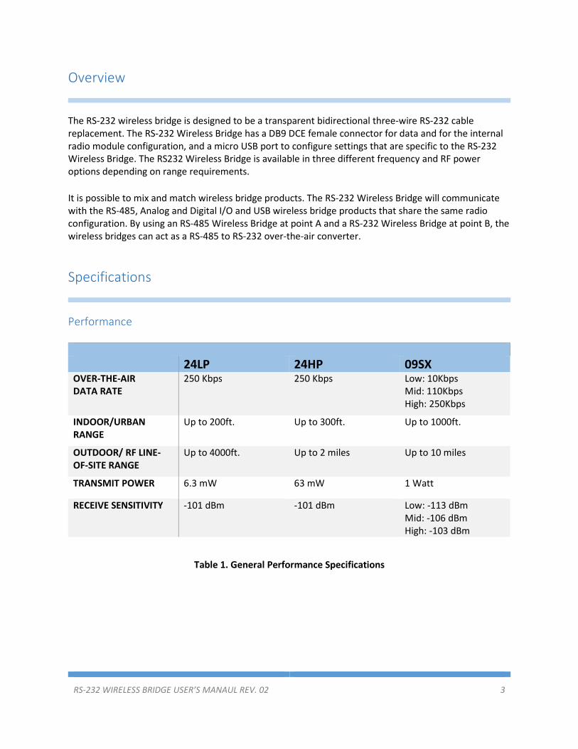
Performance
24LP 24HP 09SX OVER-THE-AIR
DATA RATE
250 Kbps 250 Kbps Low: 10Kbps
Mid: 110Kbps
High: 250Kbps
INDOOR/URBAN
RANGE
Up to 200ft. Up to 300ft. Up to 1000ft.
OUTDOOR/ RF LINE-
OF-SITE RANGE
Up to 4000ft. Up to 2 miles Up to 10 miles
TRANSMIT POWER 6.3 mW 63 mW 1 Watt
RECEIVE SENSITIVITY -101 dBm -101 dBm Low: -113 dBm
Mid: -106 dBm
High: -103 dBm
Table 1. General Performance Specifications
RS-232 WIRELESS BRIDGE USER’S MANAUL REV. 02 4
Power Requirements
24LP 24HP 09SX INPUT VOLTAGE 7-30VDC 7-30VDC 7-30VDC
TRANSMIT CURRENT 12mA @ 12V 40mA @ 12V 270mA @ 12V
RECEIVE CURRENT 12mA @ 12V 12mA @ 12V 17mA @ 12V
Table 2. Power Requirements
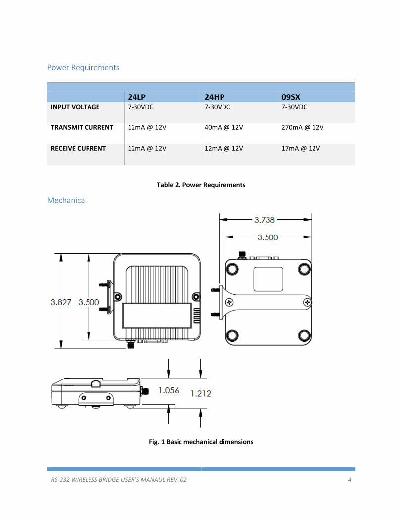
Mechanical
Fig. 1 Basic mechanical dimensions
RS-232 WIRELESS BRIDGE USER’S MANAUL REV. 02 5
The mechanical dimensions for the wireless bridge are shown in Figure 1. The mechanical dimensions
are shown with the optional DIN rail mount bracket which is not included in the basic part number.
Mechanical data for the antenna is not shown.
Pinout and Wiring
The pinout follows the standard RS-232 Data Communications Equipment (DCE) device. Signal names
for RS-232 are defined from the standpoint of a Data Terminal Equipment (DTE) device. The signal
named Receive data is an output from the RS-232 Wireless Bridge and the signal named Transmit data is
an input. Not all RS-232 signals are implemented on the Wireless Bridge. Transmit data, Receive data
and Ground are required for basic function. The DTR input may be used to control the pin sleep function
on the internal radio for reduced power draw.
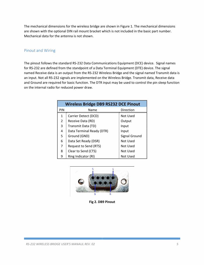
Wireless Bridge DB9 RS232 DCE Pinout
PIN Name Direction
1 Carrier Detect (DCD) Not Used
2 Receive Data (RD) Output
3 Transmit Data (TD) Input
4 Data Terminal Ready (DTR) Input
5 Ground (GND) Signal Ground
6 Data Set Ready (DSR) Not Used
7 Request to Send (RTS) Not Used
8 Clear to Send (CTS) Not Used
9 Ring Indicator (RI) Not Used
Fig 2. DB9 Pinout

RS-232 WIRELESS BRIDGE USER’S MANAUL REV. 02 6
Fig 3. Wireless Bridge Connectors and Pins
Operation
Basic Operation
The RS-232 Wireless Bridge is designed to be data transparent. By default, any data sent into one device
is broadcast and received by all other Wireless Bridge devices within range. Any device that receives the
transmitted data packet will send the received data out the serial port to its host. The Wireless Bridge
can operate in a point-to-point or point-to-multipoint mode.
The Wireless Bridge device is equipped with a micro USB connector. When the micro USB connector is
plugged into a USB host device such as a computer, the Wireless Bridge enumerates as two standard
serial COM ports. One port is a data port and can send and receive wireless data. The second COM port
is the device’s information port. When the micro USB connector is plugged into the RS-232 Wireless
Bridge, the DB9 port is disabled. The DB9 port is the default data port and is automatically used
whenever the USB cable is not plugged in.
The Wireless Bridge uses standard composite device drivers are enabled in Windows 10 and MAC
computers. Drivers will need to be installed for Windows 7 machines. While not every machine will
enumerate exactly the same, as a general. The lower numbered COM port is for Wireless Bridge
configuration. The higher numbered COM port can be used to transmit or receive data over the USB
port.
LED Indication
The wireless bridge has four LEDS for indication. The Blue Power LED is lit any time the Wireless Bridge is
properly powered. A green TX LED and a yellow RX LEDs indicate activity on the serial port of the device.
They do not necessarily reflect all activity that may be occurring over the air as they will only blink when
a properly addressed data packet is received. The Special function LED is lit when the USB port is in use.
RS-232 WIRELESS BRIDGE USER’S MANAUL REV. 02 7
Data Formats and Baud Rates
The default baud rate and data format is 9600 baud, 8 data bits, no parity and one stop bit. The baud
rate and data format can be adjusted by adjusting the BD and NB parameter of the radio module (See
the Configuring the Radio Module section). If the data of the sending or receiving devices do not
correspond with the data settings of the Wireless Bridge then data will be appear garbled.
Common Configurations and Use Cases
Radio Architectures
Point-to Point
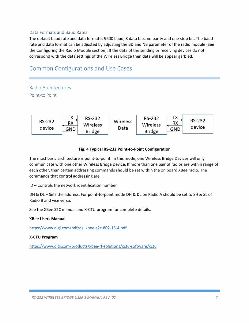
Fig. 4 Typical RS-232 Point-to-Point Configuration
The most basic architecture is point-to-point. In this mode, one Wireless Bridge Devices will only
communicate with one other Wireless Bridge Device. If more than one pair of radios are within range of
each other, than certain addressing commands should be set within the on board XBee radio. The
commands that control addressing are
ID – Controls the network identification number
DH & DL – Sets the address. For point-to-point mode DH & DL on Radio A should be set to SH & SL of
Radio B and vice versa.
See the XBee S2C manual and X-CTU program for complete details.
XBee Users Manual
https://www.digi.com/pdf/ds_xbee-s2c-802-15-4.pdf
X-CTU Program
https://www.digi.com/products/xbee-rf-solutions/xctu-software/xctu
RS-232 WIRELESS BRIDGE USER’S MANAUL REV. 02 8
Point-to-Multipoint
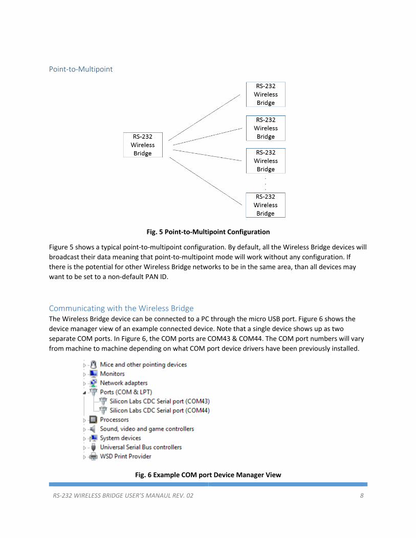
Fig. 5 Point-to-Multipoint Configuration
Figure 5 shows a typical point-to-multipoint configuration. By default, all the Wireless Bridge devices will
broadcast their data meaning that point-to-multipoint mode will work without any configuration. If
there is the potential for other Wireless Bridge networks to be in the same area, than all devices may
want to be set to a non-default PAN ID.
Communicating with the Wireless Bridge
The Wireless Bridge device can be connected to a PC through the micro USB port. Figure 6 shows the
device manager view of an example connected device. Note that a single device shows up as two
separate COM ports. In Figure 6, the COM ports are COM43 & COM44. The COM port numbers will vary
from machine to machine depending on what COM port device drivers have been previously installed.
Fig. 6 Example COM port Device Manager View

RS-232 WIRELESS BRIDGE USER’S MANAUL REV. 02 9
COM ports can be opened with any terminal program. Putty, Tera term and X-CTU may all be used to
send data and communicate with the Wireless Bridge. Links to some terminal programs can be found on
the Datawave website.
Once a COM port has been opened, pressing the ENTER key can determine which port is the data
terminal and which port is the information terminal. If a command prompt appears, than that port is the
information terminal. The command prompt for the RS-232 Wireless Bridge is
RS232>
Typing ‘help’ at the command prompt will display the menu as shown in Figure 7. Any data typed into
the data terminal window will result in the data being transmitted. This can be confirmed by watching
the TX LED blink when data is sent.
Fig. 7 Data and Information Terminals
RS-232 WIRELESS BRIDGE USER’S MANAUL REV. 02 10
RS-232 Command Reference Table
Main
command
Function Command
Name Command Description
Default
Value Value Range
help Displays list of main
commands NA No parameters
ver Displays loaded firmware
version NA No parameters
info Displays device serial number NA No parameters
set & get uart.rate
Changes the host to internal
radio baud rate. This
command should be used in
conjunction with changing the
radio baud rate.
9600 1200 - 115200
pkts.en
Enables JSON output format
when used with an ADIO
Wireless Bridge
0 0 or 1
store
Stores settings to non-volatile
memory. NA No parameters
defaults
Restores factory default
settings. NA No parameters
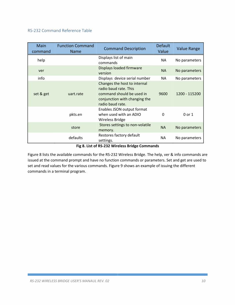
Fig 8. List of RS-232 Wireless Bridge Commands
Figure 8 lists the available commands for the RS-232 Wireless Bridge. The help, ver & info commands are
issued at the command prompt and have no function commands or parameters. Set and get are used to
set and read values for the various commands. Figure 9 shows an example of issuing the different
commands in a terminal program.
RS-232 WIRELESS BRIDGE USER’S MANAUL REV. 02 11
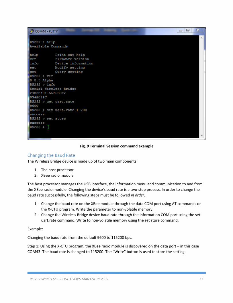
Fig. 9 Terminal Session command example
Changing the Baud Rate
The Wireless Bridge device is made up of two main components:
1. The host processor
2. XBee radio module
The host processor manages the USB interface, the information menu and communication to and from
the XBee radio module. Changing the device’s baud rate is a two-step process. In order to change the
baud rate successfully, the following steps must be followed in order.
1. Change the baud rate on the XBee module through the data COM port using AT commands or
the X-CTU program. Write the parameter to non-volatile memory.
2. Change the Wireless Bridge device baud rate through the information COM port using the set
uart.rate command. Write to non-volatile memory using the set store command.
Example:
Changing the baud rate from the default 9600 to 115200 bps.
Step 1: Using the X-CTU program, the XBee radio module is discovered on the data port – in this case
COM43. The baud rate is changed to 115200. The “Write” button is used to store the setting.

RS-232 WIRELESS BRIDGE USER’S MANAUL REV. 02 12
Fig. 10 X-CTU Baud Rate Setting
Step 2: On the Wireless Bridge information terminal – COM44 in this example, the set uart.rate 115200
is issued followed by set store.

RS-232 WIRELESS BRIDGE USER’S MANAUL REV. 02 13
Fig. 11 Uart Rate Setting Example
Configuring the XBee Module
The RS-232 wireless bridge utilizes the Digi XBee module. Consequently, all radio settings can be read or
set with Digi AT commands or The Digi X-CTU software. As a general rule the only commands that might
need be set are the Networking and Serial Interfacing commands. Any I/O commands or other features
are not used. See Digi’s website at www.digi.com and the XBee user manual and discussion forums for
more information.
Antennas
The Wireless Bridge uses an RP-SMA Female connector. The Wireless Bridge is approved to be used with
any 2.1dBi RP-SMA Male antennas that are frequency compatible. Datawave antenna part numbers
include
Part Number: ANT-2400-RP-2-A (2.4 GHz for the 24LP & 24HP variants)
Part Number: ANT-900-RP-2-A (900 MHz for the 09SX variant)
RS-232 WIRELESS BRIDGE USER’S MANAUL REV. 02 14
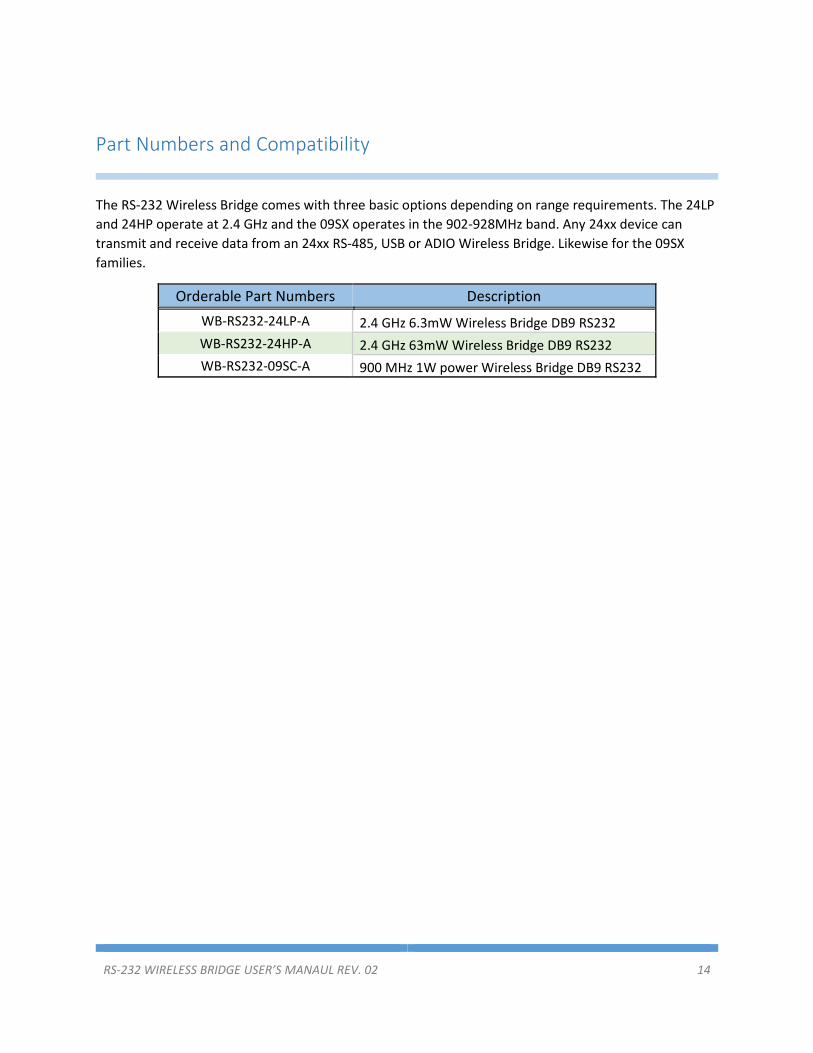
Part Numbers and Compatibility
The RS-232 Wireless Bridge comes with three basic options depending on range requirements. The 24LP
and 24HP operate at 2.4 GHz and the 09SX operates in the 902-928MHz band. Any 24xx device can
transmit and receive data from an 24xx RS-485, USB or ADIO Wireless Bridge. Likewise for the 09SX
families.
Orderable Part Numbers Description
WB-RS232-24LP-A 2.4 GHz 6.3mW Wireless Bridge DB9 RS232
WB-RS232-24HP-A 2.4 GHz 63mW Wireless Bridge DB9 RS232
WB-RS232-09SC-A 900 MHz 1W power Wireless Bridge DB9 RS232

RS-232 WIRELESS BRIDGE USER’S MANAUL REV. 02 15
Certifications
United States (FCC) The Datawave Wireless Bridges comply with Part 15 of the FCC rules and regulations.
Compliance with the labeling requirements, FCC notices and antenna usage guidelines is required.
FCC notices
IMPORTANT: The RF device has been certified for remote and base radio applications.
This equipment has been tested and found to comply with the limits for a Class B digital device, pursuant to Part
15 of the FCC Rules. These limits are designed to provide reasonable protection against harmful interference in a
residential installation. This equipment generates, uses and can radiate radio frequency energy and, if not installed
and used in accordance with the instructions, may cause harmful interference to radio communications. However,
there is no guarantee that interference will not occur in a particular installation.
If this equipment does cause harmful interference to radio or television reception, which can be determined by
turning the equipment off and on, the user is encouraged to try to correct the interference by one or more of the
following measures: Re-orient or relocate the receiving antenna, Increase the separation between the equipment
and receiver, Connect equipment and receiver to outlets on different circuits, or consult the dealer or an
experienced radio/TV technician for help.
Parts manufactured by Datawave Wireless meet the specific requirements of the EU directive (Directive
2011/65/EU of the European Parliament and of the Council of 8 June 2011 on the restriction of the use
of certain hazardous substances in electrical and electronic equipment) for the following banned
substances:
Cadmium (Cd)
Mercury (Hg)
Polybrominated Biphenyl (PBB)
Lead (Pb) (per exemption 6)
Hexavalent Chromium
Polybrominated Diphenyl ether (PBDE)


