PCB area reduced for more compatible applications DSP processing required
Sampling circuit
COMPANY PUBLIC 26
Communication
TXRX
• FSK ( Frequency Shift Keying)
• Speed: fop/512
• Bit-encoding: bi-phase
• Byte-encoding:
− Patten message : 8 bits
− Normal message: Start-bit, 8-bit data, parity-bit,
stop-bit
• Packet structure
− Header (1 Byte) : Indicates packet type and
message length
− Message (1 .. 27 Byte): identification and
configuration information
− Checksum (1 Byte)
COMPANY PUBLIC 27
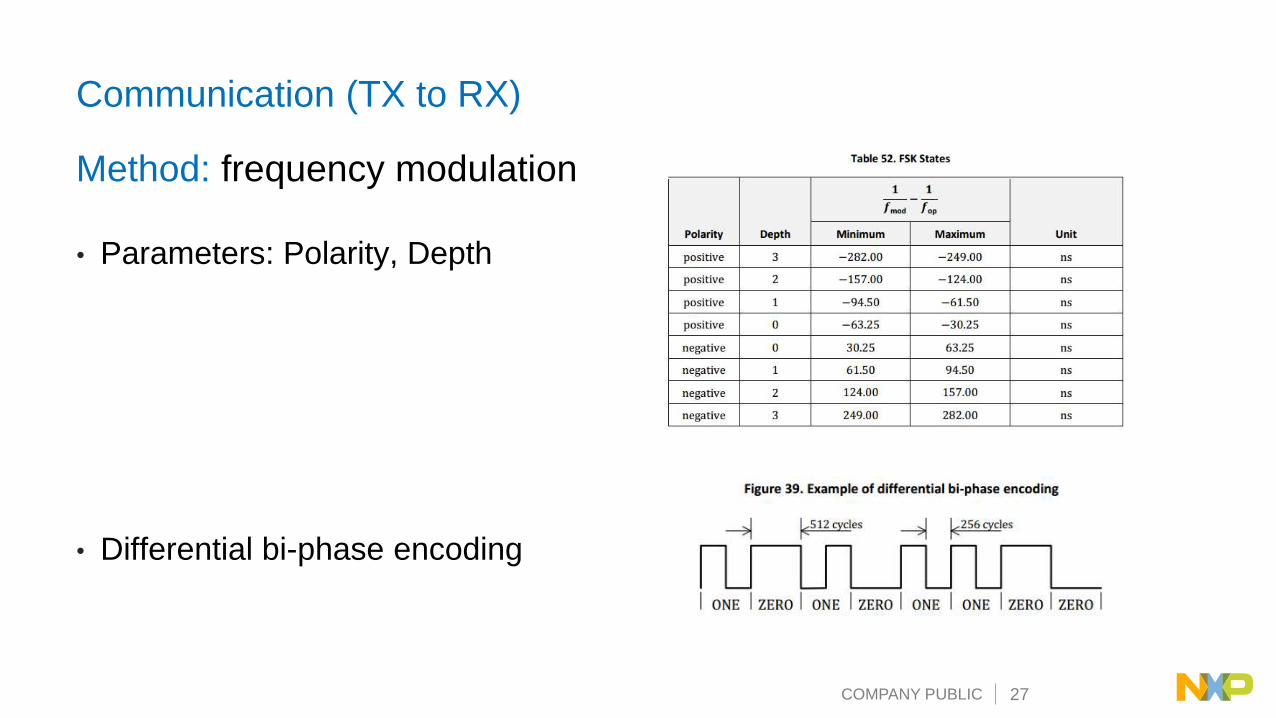
Communication (TX to RX)
Method: frequency modulation
• Parameters: Polarity, Depth
• Differential bi-phase encoding
COMPANY PUBLIC 28
Object Detection – Analog Ping
COMPANY PUBLIC 29
Object Detect – Analog Ping
• Use 5 PWM pulse, 50% duty cycle, full bridge, same frequency with
digital ping to motivate resonance waveform in TX resonance tank.
• Use ADC to sample resonance waveform.
• ADC is triggered by PWM, ADC samples once for every PWM cycle.
• ADC trigger is delayed a little from start of PWM pulse. For PWM
signal with 50% duty cycle, ADC trigger is delayed 25% PWM period.
• Only the latest ADC sample is used as analog ping sample result.
The latest ADC sample is the ADC sample after PWM pulse stops.
COMPANY PUBLIC 30
Object Detect – Analog Ping
• CH1: Resonance waveform
• CH2: PWM
• CH3: PWM
• CH4: ADC trigger
COMPANY PUBLIC 31
Foreign Object Detection (FOD)
COMPANY PUBLIC 32
FOD
• For baseline profile power RX:
− FOD based on power loss
• For extended profile power RX:
− Pre-Power transfer FOD based on Q
− FOD during Power transfer based on calibrated power loss
COMPANY PUBLIC 33
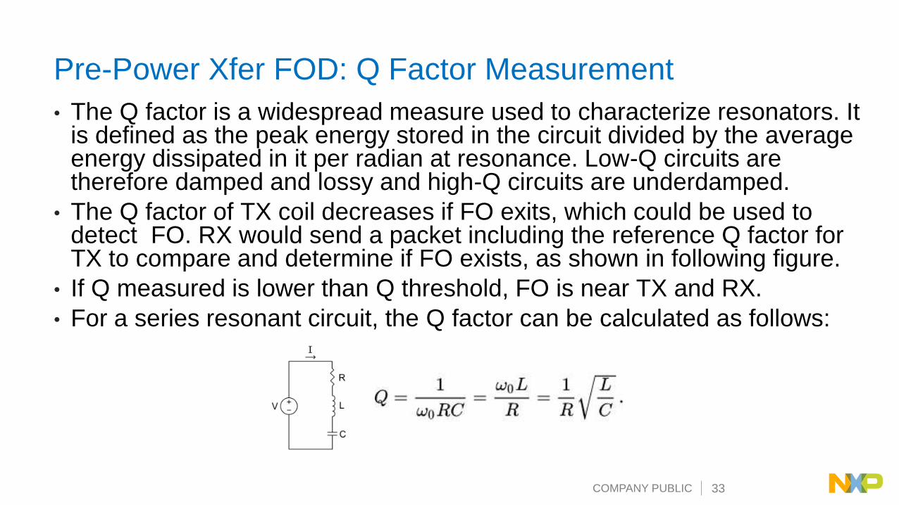
Pre-Power Xfer FOD: Q Factor Measurement
• The Q factor is a widespread measure used to characterize resonators. It is defined as the peak energy stored in the circuit divided by the average energy dissipated in it per radian at resonance. Low-Q circuits are therefore damped and lossy and high-Q circuits are underdamped.
• The Q factor of TX coil decreases if FO exits, which could be used to detect FO. RX would send a packet including the reference Q factor for TX to compare and determine if FO exists, as shown in following figure.
• If Q measured is lower than Q threshold, FO is near TX and RX.
• For a series resonant circuit, the Q factor can be calculated as follows:
COMPANY PUBLIC 34
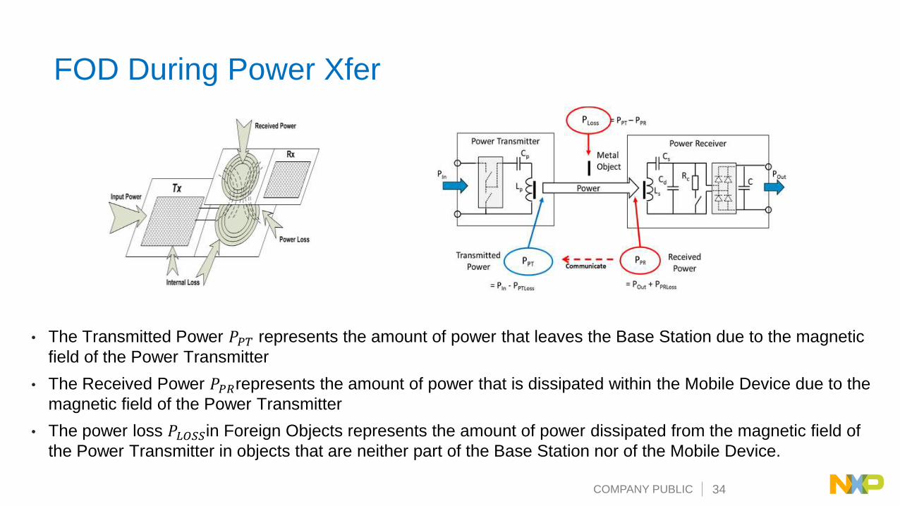
FOD During Power Xfer
• The Transmitted Power 𝑃𝑃𝑇 represents the amount of power that leaves the Base Station due to the magnetic
field of the Power Transmitter
• The Received Power 𝑃𝑃𝑅represents the amount of power that is dissipated within the Mobile Device due to the
magnetic field of the Power Transmitter
• The power loss 𝑃𝐿𝑂𝑆𝑆in Foreign Objects represents the amount of power dissipated from the magnetic field of
the Power Transmitter in objects that are neither part of the Base Station nor of the Mobile Device.
COMPANY PUBLIC 35
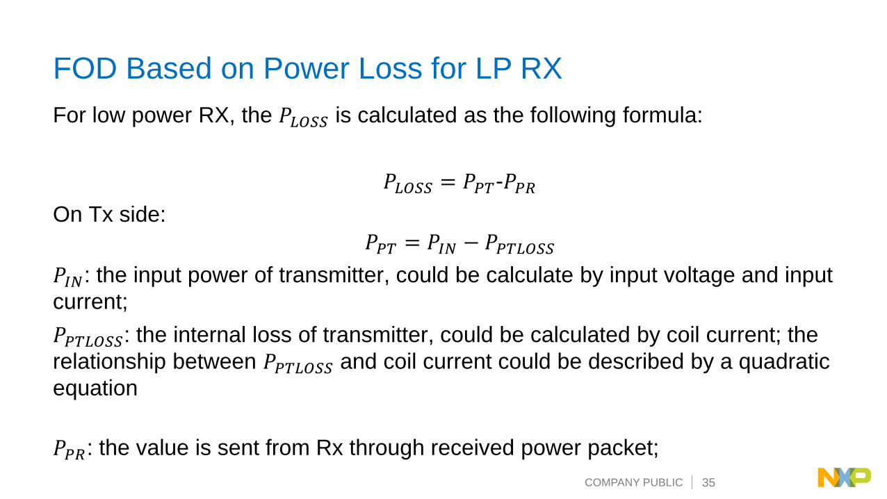
FOD Based on Power Loss for LP RX
For low power RX, the 𝑃𝐿𝑂𝑆𝑆 is calculated as the following formula:
𝑃𝐿𝑂𝑆𝑆 = 𝑃𝑃𝑇-𝑃𝑃𝑅
On Tx side:
𝑃𝑃𝑇 = 𝑃𝐼𝑁 − 𝑃𝑃𝑇𝐿𝑂𝑆𝑆
𝑃𝐼𝑁: the input power of transmitter, could be calculate by input voltage and input
current;
𝑃𝑃𝑇𝐿𝑂𝑆𝑆: the internal loss of transmitter, could be calculated by coil current; the
relationship between 𝑃𝑃𝑇𝐿𝑂𝑆𝑆 and coil current could be described by a quadratic
equation; the coefficients of the equation can be get by calibration through
FreeMASTER GUI.
𝑃𝑃𝑅: the value is sent from Rx through received power packet;
COMPANY PUBLIC 36
FOD Based on Calibrated Power Loss for MP RX
For middle power RX, the 𝑃𝐿𝑂𝑆𝑆 is calculated as the following formula:
𝑃𝐿𝑂𝑆𝑆 = 𝑃𝑃𝑇𝑐𝑎𝑙 − 𝑃𝑃𝑅
𝑃𝑃𝑇𝑐𝑎𝑙 is the calibrated transmitted power, which is used to remove the systematic bias
caused by estimated internal loss of TX and RX. And it can be gotten by the
following fomula:
𝑃𝑃𝑇𝑐𝑎𝑙 = 𝑎 ∗ 𝑃𝑃𝑇 + 𝑏
𝑃𝑃𝑇 = 𝑃𝐼𝑁 − 𝑃𝑃𝑇𝐿𝑂𝑆𝑆
The coefficients “a” and “b” is gotten during online calibration phase, including two
load conditions: a “light” load and a “connected” load.
COMPANY PUBLIC 37
15W 1COIL TX + NFC
• Qi charger typically use the Power Loss
Detection Method (PLD) to detect foreign
objects on their charger.
• Works perfectly for coins or other metallic
components.
• No detection of contactless cards, cards will
be destroyed.
• The LPCD (Low Power Object Detection) is based on
a change of the impedance of antenna-matching and
a low power wake up technology.
• After LPCD wakeup the NFC transmitter polls for any
RFID/NFC technology. On any reponse it determines
if further steps of charging are blocked.
• Specific polling scenarios are implemented to
distinguish between physical and emulated
RFID/NFC card.
• LPCD is based on a change of the impedence of
antenna-matching and low power wake up technique.
When a object is placed in charge area, NFC
antenna can trigger the wake-up.
• Foreign Object Detection • RFID HF tag / NFC card detection
COMPANY PUBLIC 38
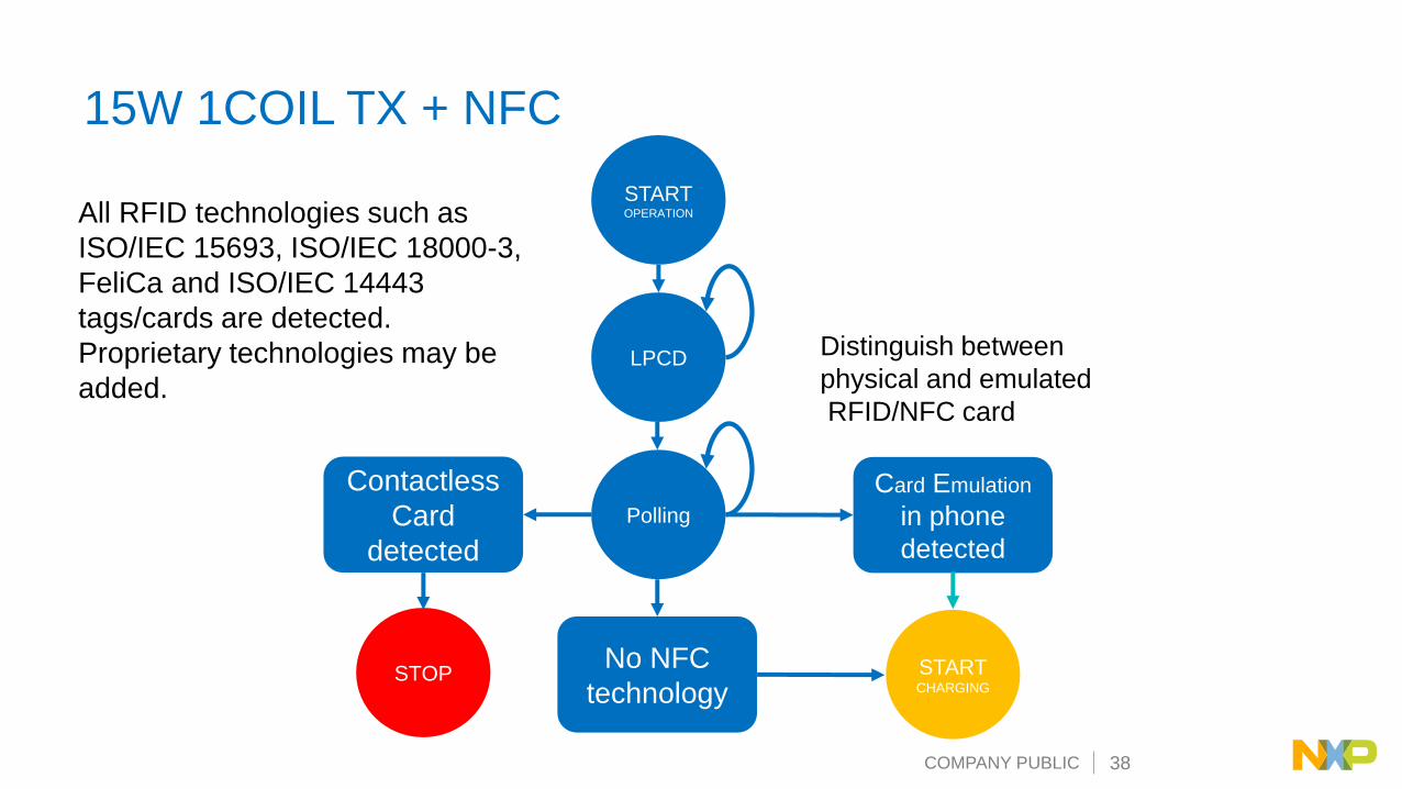
15W 1COIL TX + NFC
STARTOPERATION
LPCD
Polling
Contactless
Card
detected
STOPNo NFC
technology
Card Emulation
in phone
detected
STARTCHARGING
Distinguish between
physical and emulated
RFID/NFC card
All RFID technologies such as
ISO/IEC 15693, ISO/IEC 18000-3,
FeliCa and ISO/IEC 14443
tags/cards are detected.
Proprietary technologies may be
added.
COMPANY PUBLIC 39
NXP Wireless Charging solution
COMPANY PUBLIC 40
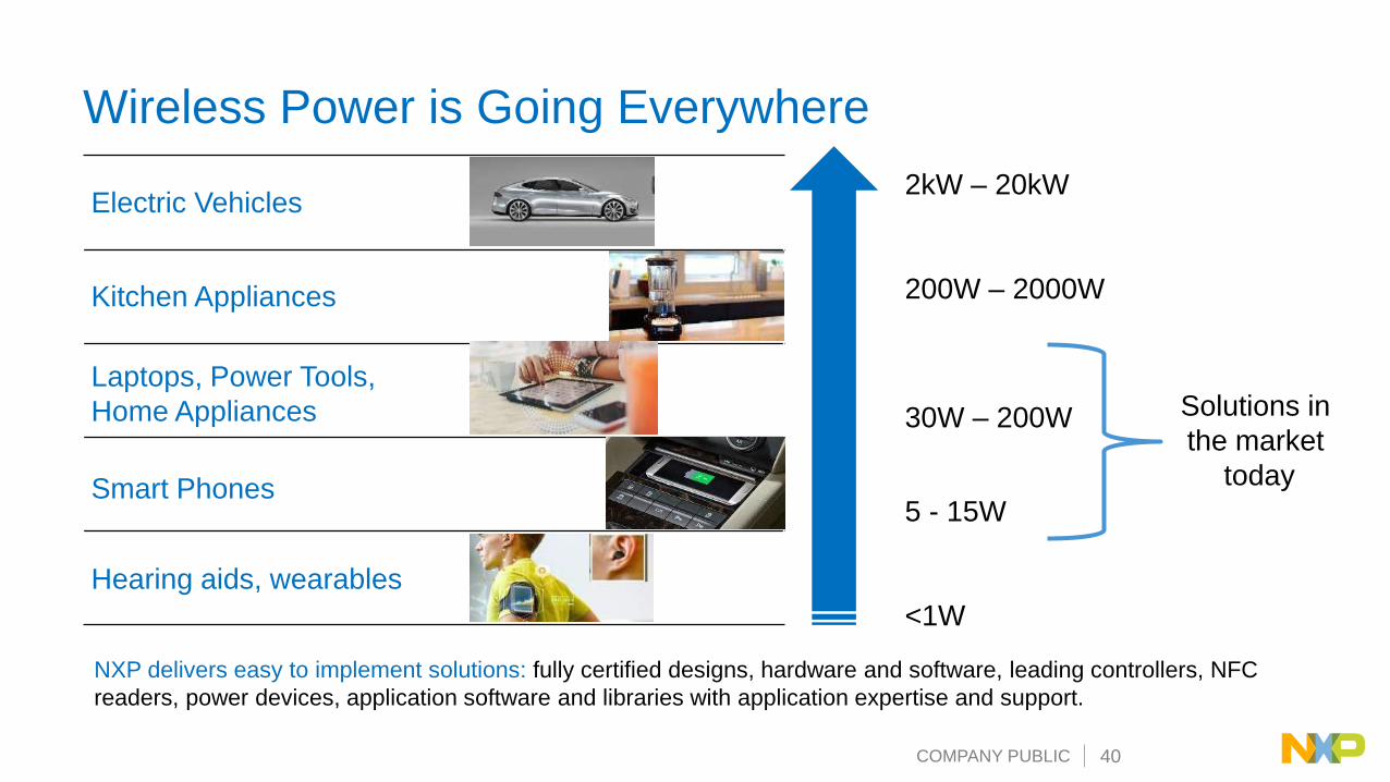
2kW – 20kW
200W – 2000W
30W – 200W
5 - 15W
<1W
Electric Vehicles
Kitchen Appliances
Laptops, Power Tools,
Home Appliances
Smart Phones
Hearing aids, wearables
Wireless Power is Going Everywhere
NXP delivers easy to implement solutions: fully certified designs, hardware and software, leading controllers, NFC
readers, power devices, application software and libraries with application expertise and support.
Solutions in
the market
today
COMPANY PUBLIC 41
NXP Wireless Charging with Fixed Operating Frequency
Why Fixed Frequency Operating Frequency is needed
• Reduce the emission to wide frequency band
• Avoid the interferences with other wireless control enabled electronics devices
− Such as remote keyless entry; Gate openers.
• Avoid the interference to AM band radio
• Meet the strict regulation in certain countries
COMPANY PUBLIC 42
MXP MP-A11: WCT-15WTX1FF15W iPhone Fast Charge Transmitter
Target Applications
• iPhone Fast Charging (7.5W)
Complete and Qi certified hardware and software solution
• Supports iPhone and Samsung Fast Charge, full 15W Qi
• Supports 1-n coils
• (Adding NFC card detection and USB PD supply)
Designed for consumer use cases
• High accuracy fixed frequency design (EMC control)
• Cost optimized design
Easy to use
• Complete hardware and software solution – charges out of the box!
• Hardware design files
Key NXP Content
• Software
• WCT controller
• NFC Reader
• USB C PD
Lead Customers
• Mophie / Belkin (in production)
• Zens, Griffin, Incipio, iHome (engaged)
COMPANY PUBLIC 43
1. ADC, hi-speed sampling
processing for accurate FOD
2. PWM controls high accurate
operation frequency and FSK
deviation
3. Digital Control Buck converter
for Vrail
4. DDM provides low cost
hardware circuits
5. GPIOs can be flexible
configured to
I2C/SCI/CAN/LED…
6. High performance MCU can
applied to run as customized
system controller
7. Flash/RAM, up-to 256KB flash
MP-A11 Block Diagram
COMPANY PUBLIC 44
Target Devices/Platforms:• MWCT1014S
Applications Usage:• 15W automotive multi-coil power TX
Application Features:• Compliant with Wireless Power Consortium (WPC) latest extended power profile
specifications to support up to 15W power transfer
• Support fast charging feature
• Integrated digital demodulation
• Power transfer efficiency exceed 70%
• Support two-way communication, transmitter to receiver by FSK and receiver to
transmitter by ASK
• Rail voltage control strategy
• Low standby power consumption
• Support MP FOD framework – Q factor and power loss FOD methods
• Support any free positioning multi-coil extended power transmitter
• Voltage/current/temperature protection
• Software based solution with Freescale embedded wireless charger software
libraries to provide maximum design freedom and product differentiation
• FreeMASTER GUI tool to enable customization and calibration
• Automotive qualified, AUTOSAR/function safety support
• NFC, CAN-FD enabled
• NXP IP
Availability:• Under development
NXP MP-A9 15W Automotive Power Transmitter
COMPANY PUBLIC 45
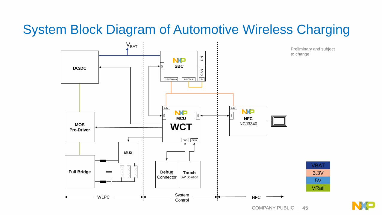
System Block Diagram of Automotive Wireless Charging
TouchSW Solution
Debug
Connector
NFC
NCJ3340
3.3V
SP
I
SBC
LIN
CA
N
5V/100mA3.3V/500mA 5V
SP
I
MCU
WCT
3.3V
SP
I
SP
I
GPIODBG
DC/DC
VBAT
MOS
Pre-Driver
Full Bridge
MUX
3.3V
VBAT
5V
VRail
WLPCSystem
ControlNFC
Preliminary and subject
to change
COMPANY PUBLIC 46
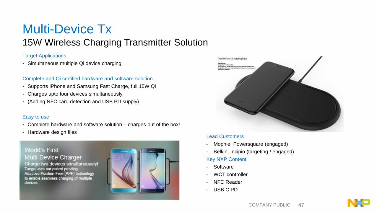
Wireless Charging 15W Transmitter Solution
Features and Enablement:
• Compliant with WPC-Qi medium power specifications
Complete and Qi certified hardware and software solution
• Supports iPhone and Samsung Fast Charge, full 15W Qi
• Charges upto four devices simultaneously
• (Adding NFC card detection and USB PD supply)
Easy to use
• Complete hardware and software solution – charges out of the box!
• Hardware design files Lead Customers
• Mophie, Powersquare (engaged)
• Belkin, Incipio (targeting / engaged)
Key NXP Content
• Software
• WCT controller
• NFC Reader
• USB C PD
COMPANY PUBLIC 48
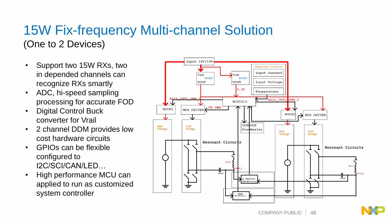
15W Fix-frequency Multi-channel Solution (One to 2 Devices)
• Support two 15W RXs, two
in depended channels can
recognize RXs smartly
• ADC, hi-speed sampling
processing for accurate FOD
• Digital Control Buck
converter for Vrail
• 2 channel DDM provides low
cost hardware circuits
• GPIOs can be flexible
configured to
I2C/SCI/CAN/LED…
• High performance MCU can
applied to run as customized
system controller
COMPANY PUBLIC 49
Quick Charge 4+ Power Bank
• QC 4+ compliance, Support QC 4, 3 and 2
• 15W Wireless Charging
• USB-type-C, Micro-USB & USB-type-A
• System and Solution provides:
– High efficiency and small from factor
– USB-PD Policy
– Real-time charger telemetry on Voltage, Current, Capacity and Temperature
– Dual-mode, Wall to battery & Battery to Devices
– Reference design + Technical support
• High NXP / QCOM BOM content, including:
– Wireless Charging Controller
– Type C and PD switches
– DCDC
– System software
COMPANY PUBLIC 50
NXP Wireless Charging Enablement
COMPANY PUBLIC 51
NXP Wireless Charging Controller Portfolio
• The basic kernel functions
of wireless charging is
packed as library form
• The add-on/customized
functions are provided as
API interfaces such as
FOD, Touch sensor, CAN,
NFC, IIC, indicator/buzzer,
etc.
• User is required to write
his/her code for those user
application code
• Sample code projects will
be provided for customer
reference to speed the
development time
COMPANY PUBLIC 52
WCT SW Layers
Application
WCT lib (binary)
WCT HAL
Platform HAL, BSP
Hardware
Callbacks
State mach
ine
Co
mm
Deco
der
PID
con
trol
Foreign
Ob
jD
etection
Co
il Selector
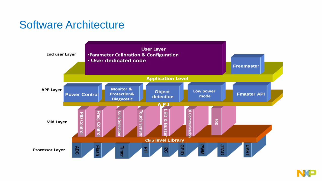
COMPANY PUBLIC 53
AD
C
Fla
sh
Tim
er
PIT
I2C
GP
IO
PW
M
JTA
G
UA
RT
Chip level Library
PID
Co
ntro
l
Fre
q. C
on
trol
Coils Selection
LE
D &
Bu
zzer
Qi
Co
mm
un
icatio
n
FOD
Tou
ch
se
ns
or
Application Level
User Layer•Parameter Calibration & Configuration• User dedicated code
A P I
Power Control Fmaster API
Monitor & Protection&Diagnostic
Object
detection
Processor Layer
Mid Layer
APP Layer
End user Layer
Low power mode
Freemaster
Software Architecture
COMPANY PUBLIC 54
SW System Diagram
Resonanc
e signal
AD
C
Q
factor
Q factor
COMPANY PUBLIC 55
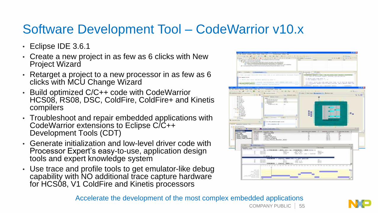
Software Development Tool – CodeWarrior v10.x• Eclipse IDE 3.6.1
• Create a new project in as few as 6 clicks with New Project Wizard
• Retarget a project to a new processor in as few as 6 clicks with MCU Change Wizard
• Build optimized C/C++ code with CodeWarrior HCS08, RS08, DSC, ColdFire, ColdFire+ and Kinetiscompilers
• Troubleshoot and repair embedded applications with CodeWarrior extensions to Eclipse C/C++ Development Tools (CDT)
• Generate initialization and low-level driver code with Processor Expert’s easy-to-use, application design tools and expert knowledge system
• Use trace and profile tools to get emulator-like debug capability with NO additional trace capture hardware for HCS08, V1 ColdFire and Kinetis processors
Accelerate the development of the most complex embedded applications
COMPANY PUBLIC 56
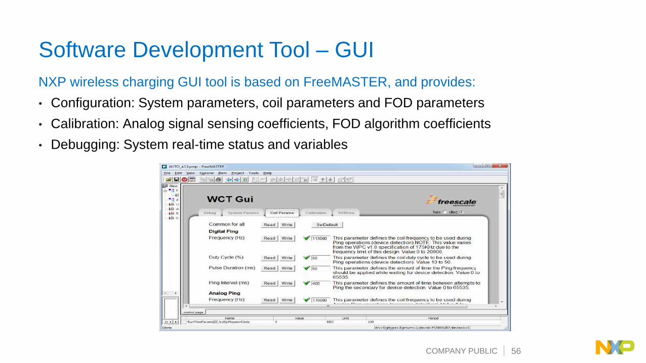
Software Development Tool – GUI
NXP wireless charging GUI tool is based on FreeMASTER, and provides:
• Configuration: System parameters, coil parameters and FOD parameters
• Calibration: Analog signal sensing coefficients, FOD algorithm coefficients
• Debugging: System real-time status and variables