Wireless Communication: Unit 3 - Wireless Network Architecture and Operation Prof. Suresha V, Dept. Of E&C E. K V G C E, Sullia, D.K-574 327 Page 1 UNIT-3 Wireless Network Architecture and Operation Learning Objectives: Upon completion of this unit, the student should be able to Understand the cellular concept and explain the advantages of frequency reuse. Know a typical cellular cluster and explain the meaning of frequency reuse number. Discuss how the capacity of a cellular system may be expanded. Explain the difference between cell splitting and sectoring. Discuss the use of backhaul networks for cellular systems. Explain the concept of mobility management and discuss the operations it supports. Discuss the concepts of power management and network security. 3.1 The Cellular Concept (a). Introduction: AT & T and Bell Labs offered first mobile telephone service. Use high power BS Txs with elevated antenna provide a larger coverage area. Typically 250 watt FM transmitter used paged a mobile when there was an incoming call for the mobile. The limitation of this system is limited users, no frequency reuse, cell congestion, high power requirement. Improvement: The main objective of cellular concept is to allocate more users in a limited allocated spectrum. The basic system characteristics are o Area divided into Cells, each served by base station with lower power transmitter covers a few hundred meters in some cities.. o Each cell gets portion of total number of channels, neighboring cells assigned different groups of channels in order to reduce the interference. o Multiple lower-power base stations that service mobile users within their coverage area and handoff users to neighboring base stations as users move. (b). The cellular Advantage. A large subscriber capacity and Efficient use of spectrum resources Nationwide coverage & Adaptability to traffic density Telephone service to both vehicle and portable user terminals including closed user groups with voice dispatch operations with Toll quality Affordability, which could eventually make it a mass-market service Power requirement for mobile is less due smaller cell and low power transmitter Longer battery life and smaller mobile station form factors.
Transcript
Wireless Communication: Unit 3 - Wireless Network Architecture and Operation
Prof. Suresha V, Dept. Of E&C E. K V G C E, Sullia, D.K-574 327 Page 1
UNIT-3
Wireless Network Architecture and Operation
Learning Objectives: Upon completion of this unit, the student should be able to
Understand the cellular concept and explain the advantages of frequency reuse.
Know a typical cellular cluster and explain the meaning of frequency reuse number.
Discuss how the capacity of a cellular system may be expanded.
Explain the difference between cell splitting and sectoring.
Discuss the use of backhaul networks for cellular systems.
Explain the concept of mobility management and discuss the operations it supports.
Discuss the concepts of power management and network security.
3.1 The Cellular Concept
(a). Introduction:
AT & T and Bell Labs offered first mobile telephone service.
Use high power BS Txs with elevated antenna provide a larger coverage area.
Typically 250 watt FM transmitter used paged a mobile when there was an incoming
call for the mobile.
The limitation of this system is limited users, no frequency reuse, cell congestion,
high power requirement.
Improvement: The main objective of cellular concept is to allocate more users in a
limited allocated spectrum. The basic system characteristics are
o Area divided into Cells, each served by base station with lower power transmitter
covers a few hundred meters in some cities..
o Each cell gets portion of total number of channels, neighboring cells assigned
different groups of channels in order to reduce the interference.
o Multiple lower-power base stations that service mobile users within their
coverage area and handoff users to neighboring base stations as users move.
(b). The cellular Advantage.
A large subscriber capacity and Efficient use of spectrum resources
Nationwide coverage & Adaptability to traffic density
Telephone service to both vehicle and portable user terminals including closed user
groups with voice dispatch operations with Toll quality
Affordability, which could eventually make it a mass-market service
Power requirement for mobile is less due smaller cell and low power transmitter
Longer battery life and smaller mobile station form factors.
Wireless Communication: Unit 3 - Wireless Network Architecture and Operation
Prof. Suresha V, Dept. Of E&C E. K V G C E, Sullia, D.K-574 327 Page 2
(c). Cellular Limitation: Initial implement cost is large due to
Deployment of large no. of low power stations
Acquisition of lands for cell sites
The associated hardware like RBS TxrRXr , controller, Antennas and towers
NOTE: But the cellular concept allows a large enough increase in capacity to make
these operations economically feasible.
(D). Implementation of basic cellular architecture:
Instead of one base station covering an entire city, the city was broken up into cells,
or smaller coverage areas. Each of these smaller coverage areas had its own lower-power
base station. The radio channels must be allocated to these smaller cells in such way as to
minimize interference but at the same time provide the necessary system performance to
handle the traffic load within the cells.
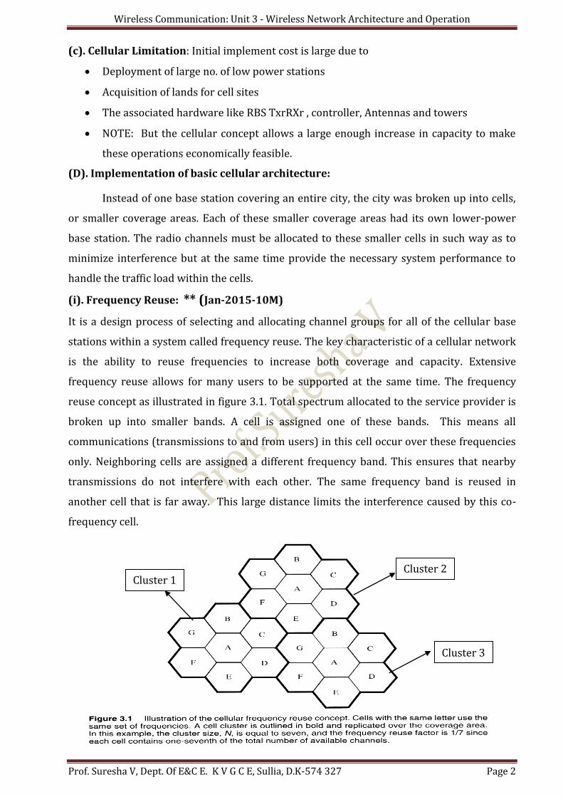
(i). Frequency Reuse: ** (Jan-2015-10M)
It is a design process of selecting and allocating channel groups for all of the cellular base
stations within a system called frequency reuse. The key characteristic of a cellular network
is the ability to reuse frequencies to increase both coverage and capacity. Extensive
frequency reuse allows for many users to be supported at the same time. The frequency
reuse concept as illustrated in figure 3.1. Total spectrum allocated to the service provider is
broken up into smaller bands. A cell is assigned one of these bands. This means all
communications (transmissions to and from users) in this cell occur over these frequencies
only. Neighboring cells are assigned a different frequency band. This ensures that nearby
transmissions do not interfere with each other. The same frequency band is reused in
another cell that is far away. This large distance limits the interference caused by this co-
frequency cell.
Cluster 1 Cluster 2
Cluster 3
Wireless Communication: Unit 3 - Wireless Network Architecture and Operation
Prof. Suresha V, Dept. Of E&C E. K V G C E, Sullia, D.K-574 327 Page 3
(ii). Cluster
It is a group of cell (see fig 3.1) that makes use of all the available radio spectrum.
Cluster has N cells with unique and disjoint channel.
Since adjacent cannot use the same frequency channels, the total frequency
allocation is divided up over the cluster and then repeated for other clusters in the
system.
The number of cells in a cluster is known as the cluster size or the frequency reuse
factor (1/N)
(iii). Illustration of cellular system capacity: An Example (June-2011-5M)
Consider service provider wants to provide cellular communications to a particular
geographic area. The provider is licensed = 5MHz. Each system subscriber bandwidth
(channel B.W) = 10 KHz.
If the service provider was to provide coverage from only one transmitter site, the
total theoretical number of possible simultaneous users = Total B.W/ Channel B.W
= 5 MHz/ 10kHz / user = 500 users.
If, however, the service provider implements a cellular system with 35 transmitter
sites, located to minimize interference and provide total coverage of area, determine
the new system capacity? Solution:
- Assume the cluster size N = 7
- The allocated B.W/cell= System B.W/ Number of cells in a cluster =5*106/7=714kHz
- Bandwidth per cell = 714 kHz.
- No. of cluster 35/7= 5.
- Each cell has a capacity =714kHz/10kHz/user = 71 users
- Total system capacity =35 cells*71 users/cell = 2485 users.
- This is a system capacity increase of =5 times.
Conclusion:
Smaller cells higher number of clusters higher Channel reuse higher
Capacity and + Lower power requirements for mobiles
o Undesirable factors: Additional base stations, More frequent handoffs and
Greater chance of ‘hot spots’
(iv). Cellular Hierarchy: It is created in the cellular system based on the cell size, as shown
in the below table. All type uses different radio link propagation & different technical cell
design concept.
Sl. No. Cell Type Cell diameter Operating Environment
1 Femtocells < 10 mts Personal Area network(PAN)
2 Picocells < 100 mt Indoor environment
3 Microcells 100-1000mts Outdoor to indoor and pedestrian
4 Macrocells >1000mts to Few Kms Vehicular and high antenna environment
5 Megacells Global coverage Vehicular and high antenna environment
Wireless Communication: Unit 3 - Wireless Network Architecture and Operation
Prof. Suresha V, Dept. Of E&C E. K V G C E, Sullia, D.K-574 327 Page 4
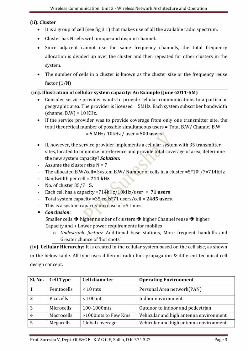
3.2. CELL FUNDAMENTALS
(i).Introduction: A Cell is a small geographic area within which each cellular base station is
allocated a group of radio channels to be used.
The Footprint: The actual radio coverage of a cell and is determined from field
measurements or propagation prediction models.
o Although Real footprint is formless in nature, a regular cell shape is needed for
systematic system design.
o Why circle cannot be used to represent the coverage area of a base station? because
adjacent circles cannot be overlaid upon a map without leaving gaps or creating
overlapping regions.
o Thus, when considering geometric shapes which cover an entire region without overlap
and with equal area, there are three sensible choices: a square; an equilateral triangle;
and a hexagon.
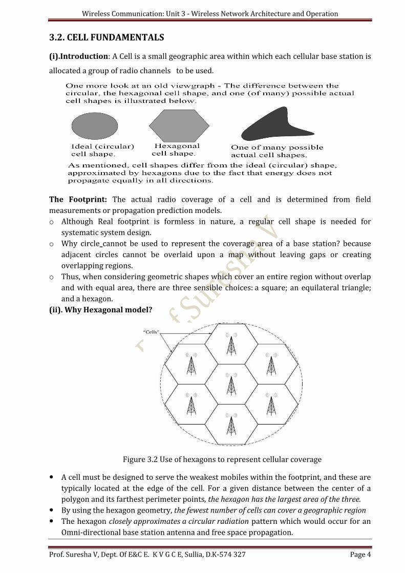
(ii). Why Hexagonal model?
Figure 3.2 Use of hexagons to represent cellular coverage
A cell must be designed to serve the weakest mobiles within the footprint, and these are
typically located at the edge of the cell. For a given distance between the center of a
polygon and its farthest perimeter points, the hexagon has the largest area of the three.
By using the hexagon geometry, the fewest number of cells can cover a geographic region
The hexagon closely approximates a circular radiation pattern which would occur for an
Omni-directional base station antenna and free space propagation.
Wireless Communication: Unit 3 - Wireless Network Architecture and Operation
Prof. Suresha V, Dept. Of E&C E. K V G C E, Sullia, D.K-574 327 Page 5
(iii). Reuse Number:
To gain the maximum reuse of the frequencies for a cellular system, cells are arranged in
clusters.
To determine the minimum size cluster that can be used it is necessary to calculate the
interference levels generated by the co-channel cells.
The reuse distance has been determined that relates cluster size N, cell radius R and the
reuse distance D.
The frequency reuse distance can be calculated by:
D = R (3N) 1/2
- Where R=cell radius and N=reuse pattern.
- Values of N can only take on numbers calculated from the following expression:
N = i2 + ij + j2, where i and j are integers.
Conclusion: If N decreased, then reuse distance D decrease, but Capacity C, Network
cost, Complexity, Handoff and Interference increase.
(iv).Relationship between cluster size (N) and reuse distance (D).
Example 1: For mobile system cluster size of 7, determine the frequency reuse distance if
the cell radius is five kilometers. Repeat the calculation for the cluster size of 4.
Solution:
Typical AMPS system uses a Cluster size of N=7, The reuse distance for cell is 5km.
Wireless Communication: Unit 3 - Wireless Network Architecture and Operation
Prof. Suresha V, Dept. Of E&C E. K V G C E, Sullia, D.K-574 327 Page 6
Use the expression N= i2 + ij + j2, one can show that possible value for N is 7. As shown in
fig 4-4, the hexagons (cells) are arranged with one hexagon in the centre of a cluster
and six other hexagons surrounding the middle hexagon. Adjacent clusters repeat the
previous pattern. The re-use distance is found from the following equation:
(1). for N=7, wkt D = R (3N) 1/2 =5(3*7)1/2 = 5(21)1/2 = 5(4.5823) = 22.913km.
(2). For N=4, D = 5(3*4)1/2 = 5(12)1/2 = 5(3.464) = 17.32km. Hence a smaller cluster
size results in a smaller re-use distance.
(v). Cellular Interference Issues (S/I)
More complex calculation can yield the S/I ratio for a particular cluster size, N.
S/I ratio gives an indication of the quality of the received signal
Using simple mathematical model for S/I ratio calculations involving unidirectional cells
yield the results tabulated in the table below for several common values of N :
Table below shows Signal to interference (S/I) ratio for various cluster sizes.
Cluster Size, N S/I ratio
3 11.3 dB
4 13.8 dB
7 18.7 dB
12 23.3 dB
Smaller cluster sizes will yield a larger possible subscriber
From above table, the trade-off is a lowered S/I ratio and the corresponding decrease in
the radio link quality.
The AMPS system did not yield usable voice quality radio links unless an S/I ratio
exceeding 18dB was available.
This value of S/I was only possible for a cluster of size 7 and up. Therefore, the typical
AMPS system was deployed with a cluster size of N=7.
The approaches to capacity expansion are either architecturally or technologically
enabled. They are
1. Cell splitting
2. Cell sectoring
3. Overlaid Cells
4. Channel allocation
5. Other capacity expansion schemes
o Lee’s Microcell Technology
o Smart Antenna Technology
o Migration to Digital Technology
Wireless Communication: Unit 3 - Wireless Network Architecture and Operation
Prof. Suresha V, Dept. Of E&C E. K V G C E, Sullia, D.K-574 327 Page 7
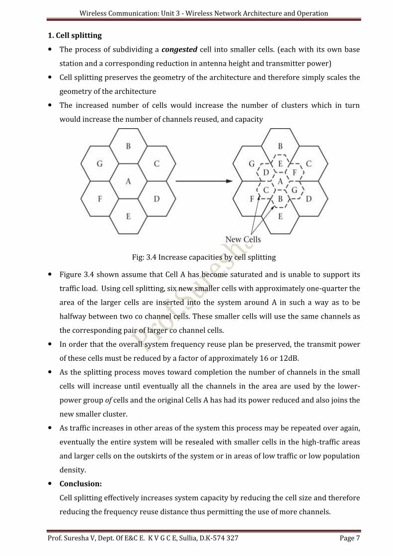
1. Cell splitting
The process of subdividing a congested cell into smaller cells. (each with its own base
station and a corresponding reduction in antenna height and transmitter power)
Cell splitting preserves the geometry of the architecture and therefore simply scales the
geometry of the architecture
The increased number of cells would increase the number of clusters which in turn
would increase the number of channels reused, and capacity
Fig: 3.4 Increase capacities by cell splitting
Figure 3.4 shown assume that Cell A has become saturated and is unable to support its
traffic load. Using cell splitting, six new smaller cells with approximately one-quarter the
area of the larger cells are inserted into the system around A in such a way as to be
halfway between two co channel cells. These smaller cells will use the same channels as
the corresponding pair of larger co channel cells.
In order that the overall system frequency reuse plan be preserved, the transmit power
of these cells must be reduced by a factor of approximately 16 or 12dB.
As the splitting process moves toward completion the number of channels in the small
cells will increase until eventually all the channels in the area are used by the lower-
power group of cells and the original Cells A has had its power reduced and also joins the
new smaller cluster.
As traffic increases in other areas of the system this process may be repeated over again,
eventually the entire system will be resealed with smaller cells in the high-traffic areas
and larger cells on the outskirts of the system or in areas of low traffic or low population
density.
Conclusion:
Cell splitting effectively increases system capacity by reducing the cell size and therefore
reducing the frequency reuse distance thus permitting the use of more channels.
Wireless Communication: Unit 3 - Wireless Network Architecture and Operation
Prof. Suresha V, Dept. Of E&C E. K V G C E, Sullia, D.K-574 327 Page 8
Advantages:
o Increases the system capacity.
o Reduces the cell size, frequency reuse distance.
o Increases the number of channels.
Disadvantages:
o Co channel interference increases
o Difficult to acquire appropriately located cell sites
o Prolonged conversion process, different cell size exists in the same area.
o No. of base station increases
o Trunking efficiency decreases and Handoff process increases
2. Sectoring
It increase capacity is to keep the cell radius unchanged and seek methods to decrease
the D /R ratio.
Uses directional antennas by replacing a single Omni-directional antenna at the base
station. It split the cell in to 3 new cells of 120o apart as shown in fig 3.5.
Figure 3.5: Increasing capacity by cell sectoring
It provides interference reduction, hence S/I ratio increases.
It does not require new cell sites and additional antennas and triangular mounting only.
Demerits: Increased network system architecture complexity
IIIustration of interference reduction due to cell sectoring as explained with fig 3.6 As shown in Figure 3.6 the sectoring of a cell results in a reduction in the amount of
interference that the sector experiences from its co channel neighbors in adjacent
Wireless Communication: Unit 3 - Wireless Network Architecture and Operation
Prof. Suresha V, Dept. Of E&C E. K V G C E, Sullia, D.K-574 327 Page 9
clusters and conversely the amount of interference that the sector supplies to its co
channel neighbors.
Fig 3.6: Interference reduction due to cell sectoring
Before sectoring, for a cluster size of 7, a cell receives and gives interference to six other
nearest co channel cells in other clusters. Now, as shown by Figure for Cell AO, the
number of interfering cells has been reduced to two (AI and A2).
This results in a higher S/I ratio for that sector and its companion sectors in other
clusters. Table below tabulates these new values for a three-sector scheme for some
common values of cluster size.
Cluster Size N S/I Ratio in dB
3 16.08
4 18.58
7 23.44
12 28.12
Comparison Between Cell splitting and Cell Sectoring Sl
no. Cell Splitting Cell Sectoring
1 Cell splitting achieves capacity improvement by essentially rescaling the system.
It is an antenna technique to increase the system capacity
2 By decreasing the cell radius R and keeping the co-channel reuse ratio D/R unchanged, cell splitting increases the number of channels per unit area.
It increase capacity is to keep the cell radius R unchanged and seek methods to decrease the D /R ratio
3 Here the number of handoffs decreases Here the number of handoffs increases
Wireless Communication: Unit 3 - Wireless Network Architecture and Operation
Prof. Suresha V, Dept. Of E&C E. K V G C E, Sullia, D.K-574 327 Page 10
4 It increase in trunking efficiency It decrease in trunking efficiency
3. Overlaid Cells
It was first introduced in the section on cell splitting.
This method can be used to expand the capacity of cellular systems in two ways.
1. Split-band analog systems.
2. Reduced cluster size systems
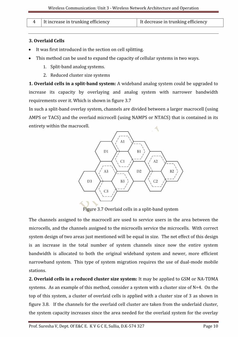
1. Overlaid cells in a split-band system: A wideband analog system could be upgraded to
increase its capacity by overlaying and analog system with narrower bandwidth
requirements over it. Which is shown in figure 3.7
In such a split-band overlay system, channels are divided between a larger macrocell (using
AMPS or TACS) and the overlaid microcell (using NAMPS or NTACS) that is contained in its
entirety within the macrocell.
Figure 3.7 Overlaid cells in a split-band system
The channels assigned to the macrocell are used to service users in the area between the
microcells, and the channels assigned to the microcells service the microcells. With correct
system design of two areas just mentioned will be equal in size. The net effect of this design
is an increase in the total number of system channels since now the entire system
bandwidth is allocated to both the original wideband system and newer, more efficient
narrowband system. This type of system migration requires the use of dual-mode mobile
stations.
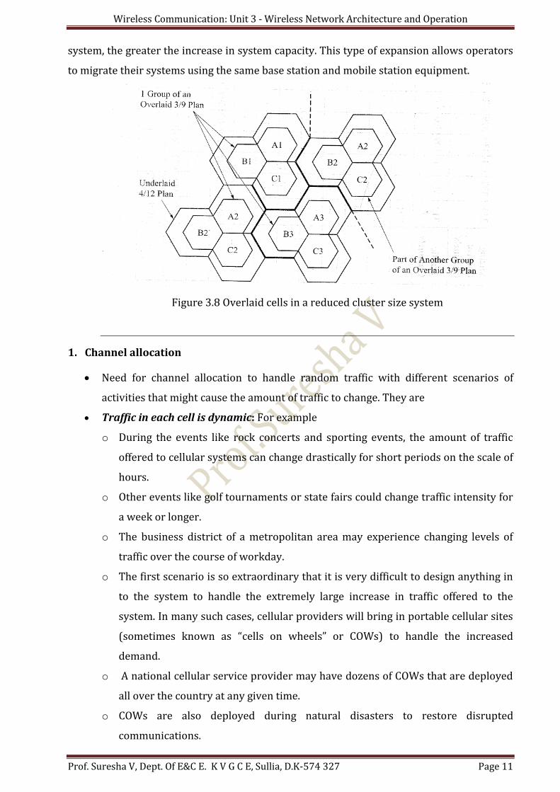
2. Overlaid cells in a reduced cluster size system: It may be applied to GSM or NA-TDMA
systems. As an example of this method, consider a system with a cluster size of N=4. On the
top of this system, a cluster of overlaid cells is applied with a cluster size of 3 as shown in
figure 3.8. If the channels for the overlaid cell cluster are taken from the underlaid cluster,
the system capacity increases since the area needed for the overlaid system for the overlay
Wireless Communication: Unit 3 - Wireless Network Architecture and Operation
Prof. Suresha V, Dept. Of E&C E. K V G C E, Sullia, D.K-574 327 Page 11
system, the greater the increase in system capacity. This type of expansion allows operators
to migrate their systems using the same base station and mobile station equipment.
Figure 3.8 Overlaid cells in a reduced cluster size system
1. Channel allocation
Need for channel allocation to handle random traffic with different scenarios of
activities that might cause the amount of traffic to change. They are
Traffic in each cell is dynamic: For example
o During the events like rock concerts and sporting events, the amount of traffic
offered to cellular systems can change drastically for short periods on the scale of
hours.
o Other events like golf tournaments or state fairs could change traffic intensity for
a week or longer.
o The business district of a metropolitan area may experience changing levels of
traffic over the course of workday.
o The first scenario is so extraordinary that it is very difficult to design anything in
to the system to handle the extremely large increase in traffic offered to the
system. In many such cases, cellular providers will bring in portable cellular sites
(sometimes known as “cells on wheels” or COWs) to handle the increased
demand.
o A national cellular service provider may have dozens of COWs that are deployed
all over the country at any given time.
o COWs are also deployed during natural disasters to restore disrupted
communications.
Wireless Communication: Unit 3 - Wireless Network Architecture and Operation
Prof. Suresha V, Dept. Of E&C E. K V G C E, Sullia, D.K-574 327 Page 12
o On the other hand, the traffic scenario within the business district can be dealt
with to some degree through channel allocation techniques.
Three main methods to achieve efficient channel allocation
1. Fixed channel scheme: The procedures of this scheme are
o Examines system wide traffic patterns over time.
o Allocating additional channels where needed to “fine-tuning” of the system. This means
that instead of equally dividing up the channels over the cells, some cells will receive
larger channel allocations than others.
o Use very complex algorithms to determine the final allocation of channels, and these
allocations are periodically updated as a traffic usage database grows and new patterns
of use emerge and periodically update this process.
2. Channel borrowing scheme: This scheme performs
o A high-traffic cell can borrow channels from low-traffic cells and keep them as needed or
until the offered traffic returns to normal.
o While borrowing channel, it should not effect on performance of the borrowed cell.
o After the traffic over the borrowed channel is complete, the channel is returned to use in
its original cell.
3. Dynamic channel allocation (DCA): It performs
o All the available channel are placed in channel pool
o Each channel assigned new call based on Signal to interference statistics
o Each Channel can used by each cell until SIR is met.
o This is an extremely complex system that uses many network resources to accomplish
its operation.
6. Other capacity expansion schemes
1. Lee’s Microcell technology
2. Smart Antenna Technology
3. Migration to newer technology
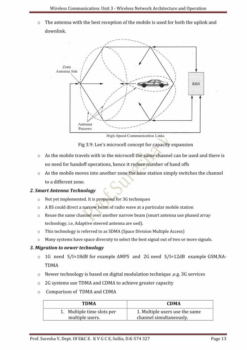
1. Lee’s Microcell technology
o In sectoring increases handoffs increasing loads on switching elements
o Here use zones instead of sectors
o It uses 3 antennas that provide coverage by “looking” into the microcell (see fig3.9).
o All 3 antennas are connected to the same BS by high-speed microwave or fiber links
Wireless Communication: Unit 3 - Wireless Network Architecture and Operation
Prof. Suresha V, Dept. Of E&C E. K V G C E, Sullia, D.K-574 327 Page 13
o The antenna with the best reception of the mobile is used for both the uplink and
downlink.
Fig 3.9: Lee’s microcell concept for capacity expansion
o As the mobile travels with in the microcell the same channel can be used and there is
no need for handoff operations, hence it reduce number of hand offs
o As the mobile moves into another zone the base station simply switches the channel
to a different zone.
2. Smart Antenna Technology
o Not yet implemented. It is proposed for 3G techniques
o A BS could direct a narrow beam of radio wave at a particular mobile station
o Reuse the same channel over another narrow beam (smart antenna use phased array
technology, i.e, Adaptive steered antenna are ued).
o This technology is referred to as SDMA (Space Division Multiple Access)
o Many systems have space diversity to select the best signal out of two or more signals.
3. Migration to newer technology
o 1G need S/I=18dB for example AMPS and 2G need S/I=12dB example GSM,NA-
TDMA
o Newer technology is based on digital modulation technique ,e.g. 3G services
o 2G systems use TDMA and CDMA to achieve greater capacity
o Comparison of TDMA and CDMA
TDMA CDMA
1. Multiple time slots per multiple users.
1. Multiple users use the same channel simultaneously.
Wireless Communication: Unit 3 - Wireless Network Architecture and Operation
Prof. Suresha V, Dept. Of E&C E. K V G C E, Sullia, D.K-574 327 Page 14
2. Immune to noise and interference
2.Interference handling capacity is inherent
3.Provide service with low S/I 3. Good S/I ratio
3.4 Cellular Backhaul Networks
o Backhaul – “Getting data to the network backbone or transmitting from a remote site
or network to a central or main site.
o The backhaul of 1G cellular system
The MSC and BS were typically connected together using T1/E1/J1 lines.
The connection between MSC & BS carried PCM-encoded voice signals at 64kbps.
T1/J1 can handle 24 voice band calls and an E1 can handle 30 voice calls.
o For 2G cellular system
Voice signals are transcoded at rate 8kbps or 16 kbps at BSC and sent over
T1/E1/J1 facilities at either allowing as many as 192 voice channels.
Fiber optic cables between MSC and PSTN, traffic was typically aggregated and, if
wanted, usually sent over larger T3 facilities that could provide for high traffic.
o For 2.5G, 2.5+G
o Cellular operator use own private wideband networks to backhaul both voice and
data between MSC and BS and from BSs to the BSCs and finally to the MSCs in an
effort to reduce costs.
o CDMA Cellular system data network connections
CDMA systems maintained the connection between the MSC and the BSC for
voice traffic.
Inter working function and packet data service node (IWF/PDSN) network
element that connects directly to the external packet network and BSC. As
shown in the fig 3.10
Wireless Communication: Unit 3 - Wireless Network Architecture and Operation
Prof. Suresha V, Dept. Of E&C E. K V G C E, Sullia, D.K-574 327 Page 15
Fig 3.10: CDMA Cellular system data network connections
o The IWF/PSDN node is responsible for proper protocol conversion and mapping
between the wireless network and the external packet network.
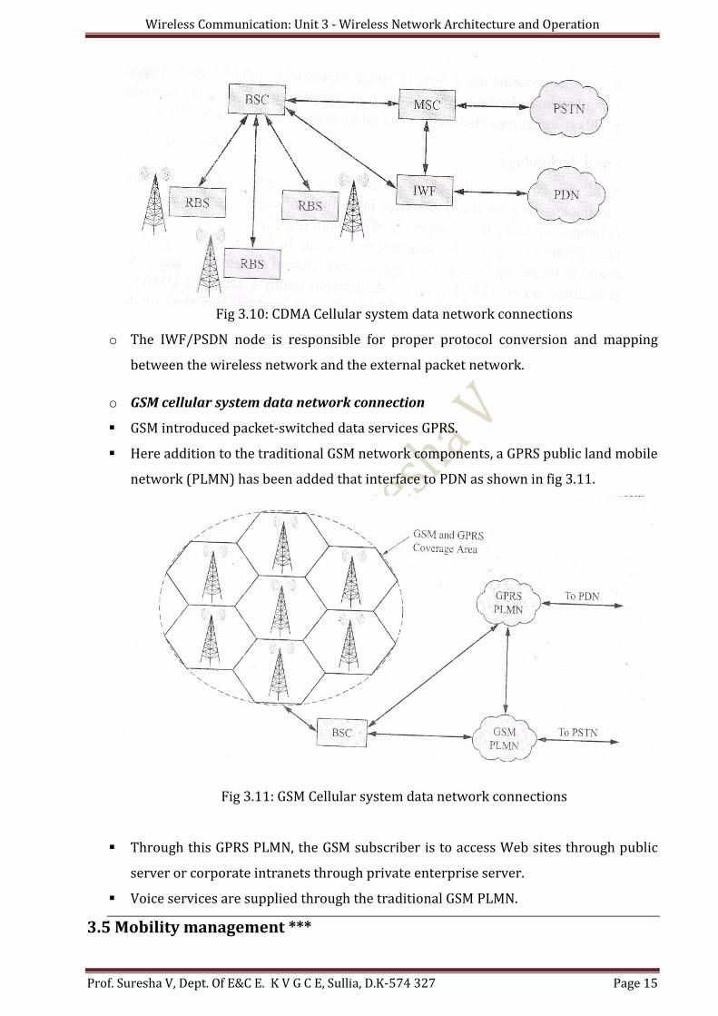
o GSM cellular system data network connection
GSM introduced packet-switched data services GPRS.
Here addition to the traditional GSM network components, a GPRS public land mobile
network (PLMN) has been added that interface to PDN as shown in fig 3.11.
Fig 3.11: GSM Cellular system data network connections
Through this GPRS PLMN, the GSM subscriber is to access Web sites through public
server or corporate intranets through private enterprise server.
Voice services are supplied through the traditional GSM PLMN.
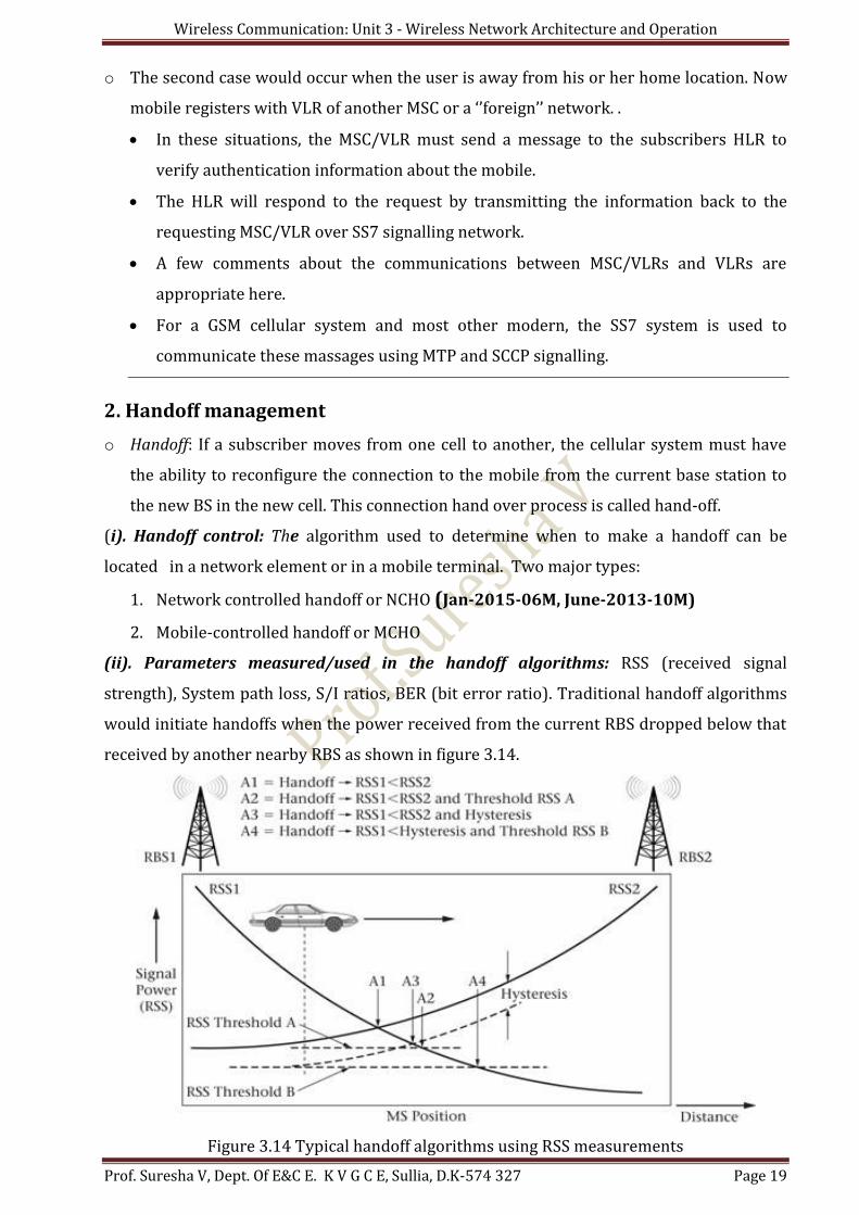
3.5 Mobility management ***
Wireless Communication: Unit 3 - Wireless Network Architecture and Operation
Prof. Suresha V, Dept. Of E&C E. K V G C E, Sullia, D.K-574 327 Page 16
It is important characteristics of wireless communication system are the ability to
provide mobility to the user.
It explains how the network knows where the subscriber is ( Location Management) and
how it keeps track of and in contact with the mobile station as the user moves from one
cell to another (Hand Off Management)
Mobility management = Location management + Hand off management
1. Location management*** (Dec-12-10M, June-2010-10M) It is the process of keeping track of the present or last known location of the MS and
delivery of both voice and data to it is move around.
Its main objectives are
1. Provide continuous radio link
2. Direct the packet in a network
3. Determine MS status in network
4. Check availability of the MS
Basic functions performed by Location management:****
1. Location updating
2. Paging messages
3. Transmission of location information between network elements
1. Location Updating
o It is performed by MS
o After initial power up registration, the MS and BS will exchange their identification
information.MS attached to a BS and is located initially and
o Periodically checked for changes
o MS sends update message every time it changes point of access(AP) in a network and
exchange information for handoff.
o If a connection fails, systems page group of surrounding stations to track a MS
o It tuned on with new registration. Balance required between number of update
messages and number of cells to be paged
o Greater degree of certainty in locating the MS & Call blocking due to frequent paging.
o Two types of updating schemes
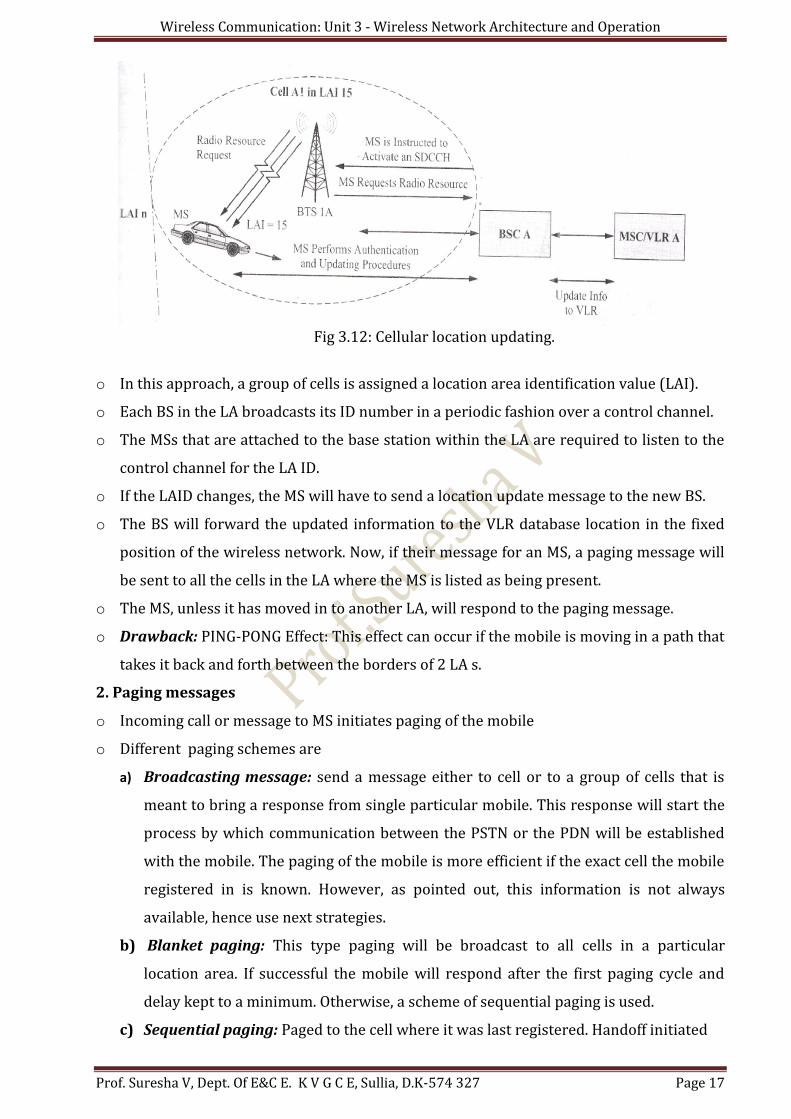
1. Static: It uses geographic layout determines updating requirements. Most
of cellular service provider uses this method as shown in figure 3.12