Naftali (Tuli) Herscovici AnTeg 52 Agnes Drive Framingham, MA 01901 USA +1 (508) 788-6226 (Fax) [email protected](e-mail) +1 (508) 788-5152 Wireless.Communications and An Overview Christos Christodoulou Department of Electricaland Computer Engineering university of New Mexico Albuquerque, NM 87131-1356 USA t1 (505) 277-1439 (Fax) [email protected](e-mail) +1 (505) 277-6580 Networking: Ramiro Jordan and Chaouki T. Abdallah Electrical & Computer Engineering Department, The University of New Mexico Albuquerque, New Mexico 87131 E-mail : { rjordan,chaouki}@eece. u n m.edu Abstract This paper presents an overview of wireless local-area networks (LANs) and wireless personal area networks (PANs), with emphasis on the two most popular standards: IEEE 802.1 1, and Bluetooth. While there are many such surveys in the current literature and online, we attempt here to present wireless LANs and PANS in a unified fashion as a viable alternative to wired LANs, while stressing the remaining challenges and limitations. Keywords:. Wireless local area networks; power control; land mobile radio data communications; personal communication networks: 802.1 1: Bluetooth 1. Introduction Wireless communications continue to enjoy exponential growth in the cellular telephony, wireless Intemet, and wireless home net- working arenas. The wireless networks reviewed in this paper include wireless local area networks (WLANs) and wireless per- sonal arca networks (WPANs) [a list of communications acronyms is given in Table 11. WPANs are differentiated from the WLANs by their smaller area of coverage, and their ad-hoc-only topology. The very first WPAN was probably the BodyLAN, resulting from a DARF’A project in the mid-1990s. It was a small-size, low-power, inexpensive network, with modest bandwidth, which connected personal devices within a range of 2 m. Motivated by this project, a WPAN group started in 1997 as a part of the IEEE 802 standardi- zation group [ 1 J [a list of communications organizations is given in Table 21. The IEEE 802.1 1 [2] group has been responsible for set- ting the standards in wireless LANs, focusing on the bottom-two layers of the Open System Interconnect (03) model (see Table 3). A similar effort is being conducted by IEEE 802.15 [3] for the wireless PANs (a list of IEEE 802 working groups is given in Table 4). This paper attempts to survey and compare the state of wire- less networking (both WLANs and‘WPANs). It is organized as follows. Section 2 presents a history of wireless communications and data. In Section 3, we discuss the challenges of mobility in communications systems, while Section 4 discusses various net- work concepts and technologies. Section 5 presents our conclu- sions. 2. History and General Concepts In this section, we present a brief overview of the history of wireless communication, and we describe the development of wireless local area networks and wide-area networks. IEEEAntenna’s and Propagation Magazine, Vol. 44, No. 1, February 2002 185
Transcript
Naftali (Tuli) Herscovici AnTeg 52 Agnes Drive Framingham, MA 01901 USA
Electrical & Computer Engineering Department, The University of New Mexico Albuquerque, New Mexico 87131
E-mail : { rjord an, chaou ki}@eece. u n m .ed u
Abstract This paper presents an overview of wireless local-area networks (LANs) and wireless personal area networks (PANs), with emphasis on the two most popular standards: IEEE 802.1 1, and Bluetooth. While there are many such surveys in the current literature and online, we attempt here to present wireless LANs and PANS in a unified fashion as a viable alternative to wired LANs, while stressing the remaining challenges and limitations.
Keywords:. Wireless local area networks; power control; land mobile radio data communications; personal communication networks: 802.1 1: Bluetooth
1. Introduction
Wireless communications continue to enjoy exponential growth in the cellular telephony, wireless Intemet, and wireless home net- working arenas. The wireless networks reviewed in this paper include wireless local area networks (WLANs) and wireless per- sonal arca networks (WPANs) [a list of communications acronyms is given in Table 11. WPANs are differentiated from the WLANs by their smaller area of coverage, and their ad-hoc-only topology. The very first WPAN was probably the BodyLAN, resulting from a DARF’A project in the mid-1990s. It was a small-size, low-power, inexpensive network, with modest bandwidth, which connected personal devices within a range of 2 m. Motivated by this project, a WPAN group started in 1997 as a part of the IEEE 802 standardi- zation group [ 1 J [a list of communications organizations is given in Table 21. The IEEE 802.1 1 [ 2 ] group has been responsible for set- ting the standards in wireless LANs, focusing on the bottom-two layers of the Open System Interconnect (03) model (see Table 3). A similar effort is being conducted by IEEE 802.15 [3] for the
wireless PANs (a list of IEEE 802 working groups is given in Table 4).
This paper attempts to survey and compare the state of wire- less networking (both WLANs and‘WPANs). It is organized as follows. Section 2 presents a history of wireless communications and data. In Section 3, we discuss the challenges of mobility in communications systems, while Section 4 discusses various net- work concepts and technologies. Section 5 presents our conclu- sions.
2. History and General Concepts
In this section, we present a brief overview of the history of wireless communication, and we describe the development of wireless local area networks and wide-area networks.
IEEEAntenna’s and Propagation Magazine, Vol. 44, No. 1, February 2002 185
Education www.gwec.org Technology alliance www.homerf.org Technical standards body www.ieee.org Global markets and www.itu.int 'standards International standards www.iso.org organization Education www.iol.unh.edu
Education www.wlana.org
acknowledge asynchronous connectionless link Advanced Mobile Phone System bit-error.rate binary phase-shift keying code-division multiple access clear-channel assessment complementary code keying complementary code-shift keying '
differential binary phase-shift keying Digital European Cordless Telecommunications differential quadrature phase-shift keying direct-sequence,spread spectrum Federal Communications Commission frequency-division multiple access frequency-hopping spread spectrum file transfer protocol Global System for Mobile Communications hypertext transfer protocol inter-frame space improved mobile telephone service international, scientific, medical International Standards Organization International Telecommunications Union logical-link control and adaptation protocol link management protocol media access control M-ary orthogonal keying network-allocation vector. orthogonal code-division multiplexing orthogonal frequency-division multiplexing open system interconnect quadrature amplitude modulation quadrature phase-shift keying pulse-code-modulation Personal Communications System pulse-position modulation request-to-send synchronous connection-oriented service-discovery protocol telephony control protocol time-division duplexing time-division multiple access US digital cellular Wired Equivalent Privacy algorithm wireless local area network wireless personal area network
first commercial trans-Atlantic wireless service was initiated, using huge ground stations and 30 m x 100 m antenna masts. World War I saw the rapid development o F communications intelligence, intercept technology, cryptography, and other technologies that later became critical to the advent of a modem wireless system.
In 1920, Marconi discovered shortwave ( < 100 m wave- length) transmission. Such waves undergo reflections, refractions, absorption, and bounce off the ionosphere, making for much more efficient transmission. The higher liequencies needed were made possible by vacuum tubes, which be8:ame available around 1906. In addition, cheaper, smaller, and bett er-quality transmitters became available. In 1915, wireless voice trmsmission between New York and San Francisco was achieved, and in 1920, the first commercial radio broadcast took place in Pittsburgh, Pennsylvania. In 1921, police cars in Detroit, Michigan, were equipped with wireless dis- patch radios. In 1935, the first telephone call around the world was made. During the World War I1 years, radio technology developed rapidly to assist with the war effort.
In 1946, the first public telephone service started in 25 major US cities. It used 120 kHz of RF'bandwidth in half-duplex mode. Then, in 1950, the FCC doubled the number of mobile channels, and improved technology cut the RF bandwidth to 60kHz. In 1960, the FM bandwidth was again cut, to 30 kHz. Also, trunking - was introduced, and telephone companies could offer full-duplex, auto-dial systems. In 1968, AT&T proposed the cellular concept to the FCC. By 1976, 543 customers ~(12 channels) could be accom- modated in the NY Bell mobile system. In 1982, the European Global System for Mobile Communications (GSM) was estab- lished; then, in 1983, the FCC allocated 666 duplex channels for the Advanced Mobile Phone System (AMPS) (40MHz in an 800MHz band, each channel with a one-way bandwidth of
Table 2. A list of some commiunications organizations.
Table 3. The OS1 seven-layer model.
2.1 History of Wireless Transmission
The following history is based mainly on [4]
The history of modem wireless communications started in 1896 with Marconi, who demonstrated wireless telegraphy by sending and receiving Morse code, based on long-wave (>> 1 km wavelength) radiation, using high-power transmitters. In 1907, the
186 /€€E Antenna's and Propagation Magazine, Vol. 44, No. 1, February 2002
Higher 802.1 1 b speeds Enhance 802.1 1 MAC and 802.1 l a PHY Enhance 802.11 MAC security
802.8 I Fiber Optics Technical Advisory group
802.11 5GSG 802.11 PC 802.1 1 R-REG 802.12
((FOTAG) -
1 Integrated Services LAN (ISLAN) working 802.9
Globalization of 5 GHz Publicity Regulatory issues Demand priority working group -
802.11f [ Access points interoperability I
807.14 ~
802.15
802.16
Cable-TV broadband communications working group Wireless Personal Area Network (WPAN) working group Resilient Packet Ring Study Group (RPRSG)
802.1 1 SG 1 Placement in Standards I
Table 5. A list of some wireless vendors. Product key: 1: the products are provided for Bluetooth; 2: the products are
provided for 802.11; 3: the products are provided for HomeRF, 4: access points and .PC cards; 5: bridges.
30 kHz). In 1984, AT&T was broken up, and the AMPS cellular system began deploying. In 1985, the FCC released the unlicensed ISM (international, scientific, and medical) bands, which were to become important in the development of wireless LANs. In 1989, the FCC granted an additional 166 channels (10MHz worth) to AMPS. In 1991, US digital cellular (USDC), or IS-54, which sup- ports three users in each 30 kHz channel, was released. This was later improved to accommodate six users per channel. In 1993, 1.8 GHz was released for the digital Personal Communications System (PCS), followed in 1994 by the introduction of IS-95 code- division multiple access (CDMA) [5]. During that year, approxi- mately 16 million cellular phones were in use.
With the advent of new digital standards, wireless data com- munication became more prevalent [6 ] . In fact, the GSM and IS-95 standards evolved, in the 1990s, to include wireless data transmis- sion as an integral part of their service. Finally, third-generation (3G) wireless systems, based on CDMA technologies, are being developed and deployed, with data and voice communications in tight integration. It is now projected that wireless data traffic will actually surpass that of voice traffic. Moreover, the cost of wireless data devices is now low enough to allow wide penetration in the home and office markets. Many universities (Camegie Mellon, Georgia Tech, University of Tennessee, etc.) are currently operat- ing a high-speed (1 1 Mbps) wireless network across their cam- puses.
2.2 Wireless Data
The original wireless networks were meant for voice traffic and, as such, are not particularly suitable for data traffic. As an example, delays of less than 100 ms are required for voice traffic, in order to avoid undesirable echoing effects, but larger delays may be tolerated for most if not all data. On the other hand, packetized speech can tolerate some packet loss, and bit-error rates (BERs) of 0.001. This may result in a slight quality loss, but no major after- math. A BER of < 0.00001 is required for data transmission, and no packet loss is allowed. Finally, telephone conversations last, on the average, between three and 20 minutes, so a setup time of a few seconds is acceptable. Data transmissions can vary from a few sec- onds for a short e-mail to minutes for a large data transfer, so the setup time should be very small. These differences greatly affect wireless LANs and PANS, as they are designed to accommodate both data and voice traffic.
2.2.1 WLANs
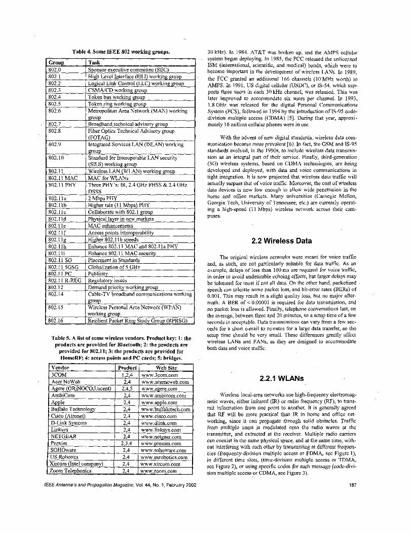
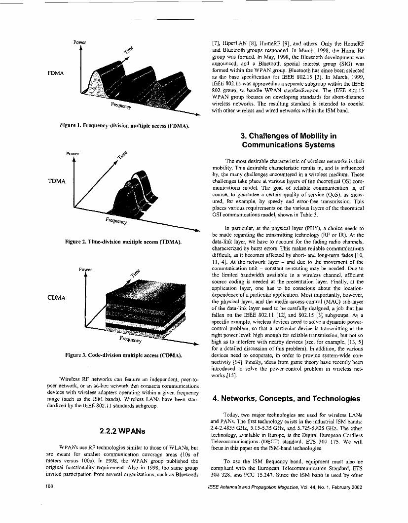
Wireless local-area networks use high-frequency electromag- 'netic waves, either infrared (IR) or radio frequency (RF), to trans- mit information from one point to another. It is generally agreed that RF will be more practical than IR in home and office net- working, since it can propagate through solid obstacles. Traffic from multiple users is modulated onto the radio waves at the transmitter, and extracted at the receiver. Multiple radio carriers can coexist in the same physical space, and at the same time, with- out interfering with each other by transmitting at different frequen- cies (frequency-division multiple access or FDMA, see Figure 1), in different time slots, (time-division multiple access or TDMA, see Figure 2), or using specific codes for each message (code-divi- sion multiple access or CDMA, see Figure 3).
1 a7 IEEE Antenna's and Propagation Magazine, Vol. 44, No. 1, February 2002
[71, HiperLAN [SI, HomeRF [9], and others. Only the HomeRF and Bluetooth groups responded. In March, 1998, the Home RF group was formed. In May, 1998, the Bluetooth development was aMoUnCed, and a Bluetooth special interest group (SIG) was formed within the WPAN group. Bluetooth has since been selected as the base specification for IEEE 802.15 [3]. In March, 1999, IEEE 802.15 was approved as a separate subgroup within the IEEE 802 group, to handle WPAN standardization. The IEEE 802.15 WPAN group focuses on developing standards for short-distance wireless networks. The resultinr standard is intended to coexist
FDMA
~l-..a'cy with other wireless and wired networks within the ISM band
3. Challenges of Mobility in Communications Systems
Power
The most desirable characteristic of wireless networks is their mobility. This desirable characteristic results in, and is influenced by, the many challenges encountered in a wireless medium. These challenges take place at V ~ ~ ~ D U S layers of the theoretical OS1 com- munications model. The goal of reliable communication is, of course, to guarantee a certain quality of service (QoS), as meas- ured, for example, by speedy and error-free transmission. This places various requirements on the various layers of the theoretical OS1 communications model, shown in Table 3.
TDMA
In particular, at the physical layer (PHY), a choice needs to he made regarding the transmitting technology (RF or R). At the data-link layer, we have to account for the fading radio channels, characterized by burst errors. This makes reliable communications difficult, as it becomes affected by short- and long-term fades [ 10, 11, 41. At the network layer - and due to the movement of the communication unit - constant re-routing may he needed. Due to the limited bandwidth available in a wireless channel. efficient
Figure 2. Time-division multiple access (TDMA).
CDM IA
Figure 3. Code-division multiple access (CDMA).
'Wireless RF networks can feature an independent, peer-to- peer network, or an ad-hoc network that connects communications devices with wireless adapters operating within a given frequency range (such as the ISM hands). Wireless LANs have been stan- dardized by the IEEE 802.11 standards subgroup.
2.2.2 WPANs
WPANs use RF technologies similar to those of WLANs, but are meant for smaller communication coverage areas (10s of meters versus 100s). In 1998, the WPAN group published the original functionality requirement. Also in 1998, the same group invited participation from several organizations, such as Bluetooth
source coding is needed at the presentation layer. Finally, at the application layer, one has to he conscious about the location- dependence of a particular application. Most importantly, however, the physical layer, and the media-access-control (MAC) sub-layer of the data-link layer need to he carefully designed, a job that has fallen on the IEEE 802.11 [12] and 802.15 [3] suhgroups. As a specific example, wireless devices need to solve a dynamic power- control problem, so that a particular device is transmitting at the right power level: high enough for reliable transmission, hut not so high as to interfere with nearby devices (see, for example, [13, 51 for a detailed discussion of this problem). In addition, the various devices need to cooperate, in order to provide system-wide con- nectivity [14]. Finally, ideas from game theory have recently heen introduced to solve the power-control problem in wireless net- works [15].
4. Networks, Concepts, and Technologies
Today, two major technologies are used for wireless LANs and PANS. The first technology exists in the industrial ISM hands: 2.4-2.4835 GHz, 5.15-5.35 GHz, and 5.725-5.825 GHz. The other technology, available in Europe, is the Digital European Cordless Telecommunications. (DECT) standard, ETS 300 175. We will focus in this paper on the ISM-band technologies.
To use the ISM frequency hand, equipment must also be compliant with the European Telecommunication Standard, ETS 300 328, and FCC 15.247. Since the ISM band is used by other
188 IEEE Anlenna's and Propagation Magazine, Vol. 44 No. 1, February 2002
equipment (such as garage-door openers and microwave ovens), avoiding interference from such equipment is important. The dif- ferent standards stipulate that spread spectrum must be used [16]. In a spread-spectrum system, users are multiplexed by assigning them different spreading keys. Such a system is called a code-divi- sion multiple access (CDMA) system. However, most wireless LAN and PAN products are not technically CDMA systems, since users belonging to the same wireless network utilize the same spreading key. Instead, users are separated in time using a carrier- sense multiple access (CSMA) protocol, similar to that used in the Ethemet.
The spreading techniques normally used in wireless LAN products can be divided into two families: frequency-hopping spread spectrum (FHSS) and direct-sequence spread spectrum (DSSS). FHSS resists interference by jumping from frequency to frequency in a pseudo-random way. The receiving system jumps synchronously, using the same pseudo-random sequence as the sender. DSSS resists interference by multiplying fast pseudo-ran- dom bits with the actual data. The receiver multiplies the same pseudo-random sequence (synchronized) by the received data, which generates the original data.
4.1 IEEE 802.11
The IEEE 802 standards committee formed the 802.11 Wire- less Local Area Networks Standards Working Group in 1987. The 802.11 working group - which contains members from intema- tional companies, universities, and organizations - first took on the task of developing a global standard for radio equipment and net- works operating in the 2.4 GHz unlicensed frequency band, for data rates of 1 and 2 Mbps. The 802.1 1 final approval was obtained in 1997. The standard does not specify technology or implementa- tion, but simply the specifications for the physical (PHY) layer and media-access-control (MAC) layer (see Table 3). The original standard called for a 2 Mbps data rate, using direct-sequence spread spectrum or frequency-hopping spread spectrum. In 1999, IEEE 802.1 l b - the high-rate standard, with data rates of up to 11 Mbps - using direct-sequence spread spectrum was adopted. Currently, IEEE 802.11a is looking into even faster rates (25 Mbps) in the 5 GHz band. The following discussion is taken mainly from [ 121.
4.1 .I Architecture
The IEEE 802.1 1 standard defines the protocol for two types of networks: ad hoc and clientfserver networks. An ad hoc network is a network where communications are established between mul- tiple nodes, without the need for an access point or server. The cli- entfserver network, on the other hand, uses an access point that controls the allocation of wireless-resources for all nodes, and allows mobile stations to roam from cell to cell. The access point is also used to interface the mobile radio to the wired or wireless backbone of the clientfserver network.
4.1.2 Media Access Control (MAC)
The access algorithm is based on carrier-sense multiple access (CSMA) with collision avoidance, or CSMMCA. The
media-access control supports a variety of physical layers, data rates, and propagation characteristics, including infrared and radio frequency. The media-access-control layer specification for 802.1 1 has similarities to the 802.3 Ethemet wired-line standard. The protocol for 802.1 1 uses carrier-sense multiple access, collision avoidance (CSMMCA). This protocol prevents collisions instead of detecting them, since collisions are bound to happen in a wire- less network, unless the protocol attempts to avoid them a priori. The media-access-control layer, together with the physical layer, samples the energy over the wireless medium. The physical layer uses a clear-channel assessment (CCA) algorithm to determine if the channel is clear. This is accomplished by measuring the RF energy at the antenna, and determining the strength of the received signal. This measured signal is commonly known as RSSI. If the received-signal strength is below a specified threshold, the channel is declared clear, and the media-access-control layer is given a green light for data transmission. If the RF energy is above the threshold, data transmissions are deferred, in accordance with the protocol’s rules. The standard provides another option for clear- channel assessment: carrier sense can be used to determine if the channel is available, by verifying that the channel contains a signal of the same carrier type as 802.1 1 transmitters, as opposed to sim- ply being corrupted by other RF transmitters. The carrier-sense multiple access, collision avoidance protocol also has options to minimize collisions, by using request-to-send (RTS), clear-to-send (CTS), data, and acknowledge (ACK) transmission frames, as described next. Communications are established when one of the wireless nodes sends a short-message request-to-send frame. The request-to-send frame includes the destination and the length of message. The message duration is termed the network-allocation vector (NAV). The network-allocation vector alerts all other nodes in the cell to “back off’ for the duration of the transmission. The receiving station issues a clear-to-send frame, which echoes the sender’s address and the network-allocation vector. If the clear-to- send frame is not received by the original sender, it is assumed that a collision occurred, and the request-to-send process starts over. After the data frame is received by the receiver node, an acknowl- edge frame is sent back to the sender, verifying successful data transmission.
A common limitation with wireless LAN systems is the hid- den-node problem. This can disrupt communication in a busy wireless environment. This problem occurs when there is a station that cannot detect the transmissions of another station, and thus assumes it is OK to transmit. As an example, assume that stations A and B are within communication range. Station C is also within communication range of station B, but not of A. Therefore, both stations A and C could try to transmit to station B at the same time. The use of request-to-send, clear-to-send, data, and acknowledge sequences helps to prevent the disruptions caused by this problem.
The IEEE 802.11 standard uses inter-frame spaces (IFS) to provide four types of priorities. The inter-frame spaces define the minimum time a station needs to wait after it senses that the medium is free. The smaller the inter-frame spaces, the higher the priority. If a collision occurs, an exponential-back-off algorithm is used to compete for the medium.
Security provisions are addressed in 802.11, as an optional feature. Data security is accomplished by the Wired Equivalent Privacy algorithm (WEP). WEP is based on protecting the trans- mitted data over the RF medium using a 64-bit seed key and the RC4 encryption algorithm. WEP only protects the data-packet information and not the physical-layer header, so that other stations on the network can listen to the control data needed to manage the
/€€€Antenna’s and Propagation Magazine, Vol. 44, No. 1, February 2002 189
network. Finally, power managcmcnt is supported at the media- access-control level for those applications requiring mobility under battery operation. Provisions are made in the protocol for the port- able stations to go to a low-powered “sleep” mode during a time interval defined by the base station.
4.1.3 IEEE 802.1 I Physical Layer
The IEEE 802.1 1 standard provides data rates of 1 Mbps with binary phase-shift keying (BPSK) modulation [17], or 2 Mbps with quadrature phase-shift keying (QPSK) modulation [ 171, for direct- sequence spread spectrum. To mitigate interference and selective fading, five 26 MHz overlapping subbands arc defined. The center frequencies are 2.412, 2.427, 2.442, 2.457, and 2.470 GHz. For frequency-hopping spread spectrum, data rates of 1 Mbps and 2Mbps are also defined. The band is divided into 79 subbands, each with a bandwidth of 1 MHz. Each subband hops at a rate of 2.5 hops/s. Unfortunately, BPSK and QPSK schemes do not meet the demands of higher-data-rate transmission schemes. To achieve the higher speeds, different modulation techniques should be implemented. The possible techniques considered by the IEEE 802.11 committee are 1) M-ary orthogonal keying (MOK), 2) complementary code keying (CCK), 3) complementary code-shift keying (CCSK), 4) pulse-position modulation (PPM), 5) quadra- ture amplitude modulation (QAM), 6) orthogonal code-division multiplexing (OCDM), and 7) orthogonal frequency-division mul- tiplexing (OFDM).
IEEE 802.1 lb selected the complementary code keying scheme, due to its resistance to multipath fading [ 10, 113 for high data rates in the 2.4 GHz band. Complementary code keying sup- ports both 5.5 Mbps and 11 Mbps modulation, and it is backward compatible with the 1-2 Mbps scheme. For the 5 GHz band, thc IEEE 802.11a task group called for a specification based on the orthogonal code-division multiplexing modulation scheme. The RF system operates in the 5.15-5.25, 5.25-5.35 and 5.725-5.825 GHz bands. The orthogonal code-division multiplexing system provides a data rate of 6-54 Mbps. The IEEE 802.1 l a and HiperLAN2 [8] physical layer will feature essentially the same physical layer.
In the direct-sequence spread spectrum systems, differential binary phase-shift keying (DBPSK) and differential quadrature phase-shift keying (DQPSK) [ 171 are used. Frequency-hopping spread spectrum uses 2-4 level Gaussian frequency-shift keying (FSK) as the modulation signaling method. The radiated RF power is set by the rules govemed by FCC part 15 for operation in the United States. The antenna gain is also limited to 6 dBi maximum. The radiated power is limited to 1 W for the United States, 10 mW pcr 1 MHz in Europc, and 10 mW for Japan.
The physical-layer data rates for frequency-hopping spread spectrum and direct-sequence spread spectrum systems are 1 Mbps and 2 Mbps, as stated before. The choice between frequency-hop- ping spread spectrum and direct-sequence spread spectrum will depend on a number of factors related to the user’s application and the environment in which the system will be operating. The direct- sequence spread spectrum physical layer uses an 1 1-bit Barker sequence to spread the data before it is transmitted. Each bit trans- mitted is modulated by the 1 1-bit sequence. The processing gain of the system is defined as ten times the log of the ratio of the spreading rate (also known as the chip rate) to the data. The receiver de-spreads the RF input to recover the original data. This provides 10.4 dB of processing gain, which meets the minimum
190
requirements for the FCC rules. The spreading architecture used in the direct-sequence physical laycr is not to bc confuscd with CDMA. All 802.11 compliant products utilize the same pseudo- random code and, therefore, do not have a set of codes available, as is required for CDMA operation.
The frequency-hop physical layer has 22 hop patterns from which to choose. The frequency-hopping spread spectrum physical layer is required to hop across the 2.4 GHz ISM band, covering 79 channels. Each channel occupies 1 MHz of bandwidth, and ,must hop at the minimum rate specified by the regulatory bodies of the intended country. A minimum hop rate of 2.5 hops per second is specified for the United States.
4.2 Bluetooth or IEEE 802.15
Bluetooth (named after the Viking king who unified Den- mark and Norway in the 10th century) is an open standard for short-range ad hoc wireless voice and data networks, operating in the unlicensed ISM 2.4 GHz frequency band. Bluetooth was origi- nally conceived by Ericsson in 1994. In 1998, Ericsson, Nokia, IBM, Intel, and Toshiba formed a special interest group (SIG) to expand the concept and to develop a standard under IEEE 802.15. Currently, over 2000 companies are participating in the Bluetooth SIG, and many are developing Bliietooth products. The Bluetooth SIG considers three application scenarios. The first is wire replacement, to connect a PC or laptop to its peripherals. The sec- ond is the ad hoc networking of several different users at short ranges in a small area, forming a “piconet,” similar to but smaller than an IEEE 802.1 1 cell. The third is to use Bluetooth as an access point to wide-area voice and data services provided by a wired network or cellular system. The last two application scenarios are in direct competition with the intended use of IEEE 802.1 1 .
Bluetooth transmits at 1 mV1 (0 dBm), using hybrid direct- sequence spread spectrum and frequency-hopping spread spectrum technologies. It can accommodate up to three voice channels or seven data channels per piconet, and a data speed of 721 Kbps per piconet. Its expected system range is around 10 m. It .can support up to eight devices per piconet, and 10 piconets in a given coverage area. It can provide some security at the link layer, and requires 2.7 V as a power source. Finally, a Bluetooth device consumes 30pA in sleep mode, 60 pA in hold mode, 300 pA in the standby mode, and 8-30 mA while transmitting.
4.2.1 Architecture
The topology of Bluetooth is referred to as a scattered ad hoc network. The network has to be sAf-reconfigurable, so that it can adapt to constantly changing users and resources. To implement this, the Bluetooth system provides different states for connecting to and disconnecting from the network. In addition, Bluetooth sta- tions have the capability of co-existing in multiple networks. The underlying access method allows the formation of small, independ- ent ad hoc cells, as well as the capability for connecting to existing large voice and data networks. Bluetooth also requires the interop- erability of protocols (to accommodate heterogeneous equipment) and their re-use.
The Bluetooth architecture defines a small cell, called a piconet, and identifies four states fix the stations: master (M), slave
/€€E Antenna’s and Propagation Magazine, Vol. 44, No. 1, February 2002
(S), standby (SB), and parked or hold (P). Each station can be in system that employs system polling to establish a link. The 1600 the master or slave state. Slave stations can participate in one or hops per second allow short time slots of 625 ps (625 bits at more piconets. A master station can handle seven simultaneous 1 Mbps) for one packet of transmission, which allows good per- links, and up to 200 active slaves in a piconet. If access is not pos- formance in the presence of interference. Frequency-hopping sible, a station enters the standby mode, waiting to join a piconet, CDMA allows tens of piconets to overlap in the same area, pro- but keeping its media-access control address. A station can be in viding an effective throughput that is greater than 1 Mbps. The the parked mode - that is, in a low-power connection - but in this access method in each piconet is time-domain multiple access/ case, it must release its media-access-control address. Up to 10 time-division-duplexing. Time-domain multiple access allows piconets can operate in one area. multiple voice and data stations to participate in a piconet. Time-
division duplexing (TDD) eliminates crosstalk between the trans- mitter and receiver. This allows a single-chip implementation, in which the radio alternates between transmitter and receiver modes. To share the medium among a large number of stations, at each slot the master station decides and polls a slave station. Polling is using instead of contention methods, because contention requires more overhead for the short packets (625 bits) that were selected for implementation of a fast frequency-hopping spread spectrum system.
The Bluetooth protocol stack for voice, data, and control sig- ’ naling consists of the following pieces: an RF layer, a baseband layer, a link-management-protocol (LMP) layer, a logical-link control and adaptation protocol (L2CAP) layer, a service-discovery protocol (SDP) layer, a telephony control protocol (TCS) layer, an RFCOMM layer, and the application layer. The overall structure of the protocol stack in Bluetooth does not completely match the OS1 model (which’is, after all, theoretical) and acronyms. The RF layer specifies the radio modem. The baseband layer specifies the link control at the bit and packet levels. It also specifies coding and ,
encryption for packet assembly and frequency-hopping operation. The link-management-protocol (LMP) layer configures the links by providing encryption and authentication, the state of stations in the piconet, power modes, traffic scheduling, and packet format. The logical-link control and adaptation protocol (L2CAP) layer provide connection-oriented or connectionless services to upper-layer pro- tocols, services such as multiplexing, segmentation and re-assem- bly of packets, and group abstractions for data packets up to 64 kB in size. The audio signal is directly transferred from an application to the baseband layer. Also, applications and the link-management- protocol layer exchange control messages to prepare the physical transport to a particular application. Different applications may use different protocol stacks, but all of them share the same physical and data-link control mechanisms. There are three other protocols above the logical-link control and adaptation protocol (L2CAP) layer. The service-discovery protocol (SDP) layer finds the char- acteristics of the services, and connects two or more Bluetooth devices to support a service such as faxing, teleconferencing, or e- business transactions. The telephony-control protocol (TCS) layer defines the call-control signaling and mobility management for the establishment of cordless applications. With these protocols, leg- acy telecommunication applications can be supported and devel- oped. The RFCOMM layer is a “cable replacement” protocol, which emulates standard RS-232 control and data signaling over the Bluetooth baseband. Using RFCOMM, legacy applications can be supported.
Audio data can be transferred between one or more Bluetooth devices. Various usage models are possible, and audio data in syn- chronous connection-oriented (SCO) packets is routed directly to and from the baseband layer, and it does not go through the logical- link control and adaptation protocol. The audio model is relatively simple within Bluetooth: any two Bluetooth devices can send and receive audio data between each other just by opening an audio link. The Bluetooth air interface is either a 64 kbps log pulse-code- modulated (PCM) format (A-law or p-law [4]), or a 64 kbps con- tinuous variable-slope delta modulation (CVSDM). The latter for- mat applies an adaptive delta-modulation algorithm with syllabic companding. The voice coding on the line interface should have a quality equal to or better than the quality of 64 kbps log pulse-code modulation.
The Bluetooth specifications provide for user protection and information confidentiality. There are three methods of operation: non-secure, service-level, and link-level security. Devices can also be classified into trusted and distrusted. Bluetooth security makes use of two secret keys: it uses 128 bits for user authentication, and eight to 128 bits for data encryption. It also uses 128 bits for ran- dom-number generation and for the 48-bit media-access-control address of devices. Any pair of stations will create a session or link key using an initialization key, the devices’ media-access-control address, and a personal-identification number (PIN).
The overall Bluetooth protocols can be divided into three 4.2.3 Physical Or Baseband and RF Layers groups. The core, exclusively-Bluetooth-specific protocols are the baseband, the link-management-protocol, the logical-link control and adaptation protocol, and the service-discovery protocol. Proto- cols developed based on existing protocols include the RFCOMM and telephony-control protocol binary and AT commands. The third group consists of protocols adopted by the Bluetooth SIG [7]. The Bluetooth specification is open, and other legacy protocols, such as HTTP (hypertext transfer protocol) and FTP (file transfer protocol) can be accommodated on top of the existing Bluetooth stack.
The RF and baseband layers of Bluetooth are located in the OS1 physical (PHY) layer. The Baseband layer contains the hard- ware that tums received radio signals into a digital form that can be processed by the host application. It also converts digital or voice data into a form that can be transmitted using a radio signal. Each packet contains information about where it is coming from, what frequency it is using, and where it is going. Packets also contain information on how the data was compressed, the order in which the packets were transmitted, and information used to verify the effectiveness of the transmission. When the data is received, it is checked for accuracy, extracted from the packet, reassembled, decompressed, and possibly filtered. The baseband processor han- dles all the tasks just described. It takes care of converting data 4.2.2 Media Access Control from one form to another (such as from voice to digital data),com- pressing it, putting it into packets, taking it out of packets, assign- ing identifiers and error-correction information, and then reversing
The media-access mechanism in Bluetooth is a fast fre- quency-hopping spread spectrudCDMNtime-division-duplexing
/€€€Antenna’s and Propagation Magazine, Vol. 44, No. 1, February 2002 191
the entire process for data that is received. In Bluetooth, the base- band function is called the link controller.
As mentioned earlier, the Bluetooth radio is a short-distance, low-power radio, which operates in the unlicensed ISM spectrum at 2.4 GHz, using a nominal antenna power of 0 dBm. At 0 dBm, the range is 10 m, meaning pieces of equipment must be within 10 m of each other (about 33 ft) to communicate using the Blue- tooth standard. Optionally, a range of 100 m (about 328 ft) may be achieved by using an antenna power of 20 dBm. Data is transmit- ted at a maximum gross rate of up to 1 Mbps. Communication- protocol overhead limits the practical data rate to a little over 72 1 kbps. Interference, or being out of range, may increase the bit- error rate (BER) and require packets to be re-sent, further decreas- ing the achievable data rate. The 2.4 GHz frequency is shared by other types of equipment, not the least being the IEEE 802.11 equipment. As a result, interference with Bluetooth devices is inevitable. The Bluetooth specification addresses this issue by using a two-level GFSK modem, employing frequency-hopping spread-spectrum techniques. The two-level GFSK modem allows a simple non-coherent detection implementation using FM demodu- lators. Bluetooth uses seventy-nine hop frequencies, spaced 1 MHz apart, in the frequency range of 2.402 to 2.480 GHz. The hop rate is 1600 hops per second (625 ps dwell time at each frequency). U the transmission encounters interference, it waits for the next fre- quency hop, and re-transmits on a new frequency. Each piconet ir. assigned a specific frequency-hopping pattern. The pattern ir determined by the piconet identity and the master clock of the master station. The overall hopping pattern is divided into two 32. hop segments, odd and even. Each 32-hop pattern starts at a poin in the spectrum, and hops over a pattern that covers 64 MHz. Afte completion of each segment, the sequence is altered, and the pat tem is shifted 16 frequencies in the forward direction. The 32 hop are concatenated, and the random selection of the index is change, for each new segment. The baseband layer uses inquiry and pagin- procedures to synchronize the transmission-hopping frequency and clock of different Bluetooth devices. It provides two different kinds of physical links with their corresponding baseband packets, syn- chronous connection-oriented (SCO) and asynchronous connec- tionless (ACL), which can be transmitted in a multiplexed manner on the same RF link. Asynchronous connectionless packets are used for data only, while the synchronous connection-oriented packet can contain audio only, or a combination of audio and data. All audio and data packets can be provided with different levels of forward error correction or cyclical-redundancy checked (CRC) error correction, and can be encrypted. Furthermore, the different data types, including link management and control messages, are each allocated a special channel. The Bluetooth system provides a point-to-point connection (only two Bluetooth units involved), or a point-to-multipoint connection. In the point-to-multipoint connec- tion, the channel is shared among several Bluetooth units. Two or more units sharing the same channel form a piconet. One Bluetooth unit acts as the master of the piconet, whereas the other unit(s) acts (act) as slave(s). Up to seven slaves can be active in the piconet. In addition, many more slaves can remain locked to the master in a so-called parked state. These parked slaves cannot be active on the channel, but remain synchronized to the master. Both for active and parked slaves, the channel access is controlled by the master. Multiple piconets with overlapping coverage areas form a “scatter- net.” Each piconet can only have a single master. However, slaves can participate in different piconets on a time-division-multiplexed basis. In addition, a master in one piconet can be a slave in another piconet. The piconets are not to be time or- frequency synchronized. Each piconet has its own hopping channel. Two link types may be defined between a master and slave(s): 1) synchronous connection-
oriented (SCO) links, and 2) asynchronous connection-less (ACL) links. The synchronous connection-oriented link is a point-to-point link between a master and a single slave in the piconet. The master maintains the synchronous connection-oriented link by using reserved slots at regular intervals, The asynchronous connection- less link is a point-to-multipoint link between the master and all the slaves participating on the piconet. In the slots not reserved for the synchronous connection-orienied link(s), the master can estab- lish an asynchronous connection-less link on a per-slot basis to any slave, including the slave(s) already engaged in an synchronous connection-oriented link.
4.3 Convergeiice Scenario
The application spaces of Bluetooth and IEEE 802.11 over- lap. Many of the applications envisioned for IEEE ’802.1 1 are also defined for Bluetooth. Yet, there are situations and conditions where IEEE 802.11 is better suited for transmitting data than Bluetooth, and vice versa. Both IEEE 802.1 1 and Bluetooth con- sider data exchange as a primary function. Bluetooth and IEEE 802.1 1 both use the same upper-layer protocol to implement these data-transfer applications, which zllows Bluetooth and IEEE802.11 devices to coexist.
Bluetooth’s maximum mobility within the piconet allows for data-exchange applications that may be difficult with IEEE 802.1 1. For example, with Bluetooth, a person could synchronize their phone with a PC without taking the phone out of their pocket. An important feature of both Bluetooth and IEEE 802.1 1 is the ability to wirelessly connect to a wired network. Bluetooth’s multipoint capability allows multiple devices to efficiently share the media. The one potential area of weakness for Bluetooth, compared to IEEE 802.1 1, is performance. Bluetooth’s aggregate bandwidth is limited to 1 Mbps, while IEEE 802.11 supports 11 Mbps, with 25 Mbps under development. Moreover, the Bluetooth coverage area is much smaller than that of IEEE 802.11.
A native feature of the Bluei.ooth specification is synchronous voice channels. Bluetooth has tht: ability to reserve bandwidth for carrying digital voice data. Finally, note that IEEE 802.11 devices are currently widely available and cost effective. Some manufac- turers have completely integrated IEEE 802.1 1 solutions into their computers. However, Bluetooth’s promise remains unfulfilled as of today, although Bluetooth gadgets are beginning to appear (see Table 5).
Note that recent work is a h being done on marrying IEEE 802.1 1 to the Telecommunicaiions Industry AssociatiodElec- tronics Industry Alliance (TWEIA) IS-856 standard [18]. While IEEE 802.1 1 focuses on WLANs. IS-,856 deals with wireless wide- area networks ranging to the tens of kilometers.
5. ConcAusions
In this paper, we have presented an overview of wireless LANs and PANS, stressing the two most-common standards, IEEE 802.1 1 and Bluetooth. While limited in scope, we have attempted to give the reader a quick comparison between the two technolo- gies, stressing various problem:;, and solutions to wireless net- working problems.
192 /€€€Antenna’s and Propagation Magazine, Vol. 44, No. 1, February 2002
6. References
1. IEEE 802 Group Web site: http://grouper.ieee.org/groups/802.
2. IEEE 802.11 Group Web site: http://grouper.ieee.org/groups/802 . /11.
3. IEEE 802.15 Group Web site: http://grouper.ieee.org/groups/802 115.
4. T. S. Rappaport, Wireless Communications: Principles and Practice, Upper Saddle River, New Jersey, Prentice Hall, 2002.
5. A. J. Viterbi, CDMA Principles of Spread Spectrum Communi- cation, Reading, MA, Addison-Wesley, 1995.
6. V. K. Garg, Wireless Network Evolution: 2G to 3G, Upper Sad- dle River, New Jersey, Prentice Hall, 2002.
7. Bluetooth SIG Web site: http://www.bluetooth.org.
8. HiperLAN2 Global Forum Web site: http://www.hiperlan2.com ,
9. HomeRF Web site: http://www.homerf.org.
10. W. C. Y. Lee, Mobile Cellular Telecommunications Systems, New York, McGraw Hill, 1989.
11. M. Yacoub, Foundations of Mobile Radio Engineering, CRC Press, 1993.
12. IEEE, Wireless Media Access Control (MAC) and Physical Layer (PHY) Specification, P802.11D6.2, July 1998.
13. Aly ElOsery, Autonomous Power Control in CDMA Cellular ‘Systems, PhD dissertation, EECE Department, University of New Mexico, 2001.
14. P. Gupta and P. Kumar, “The Capacity of Wireless Networks,” IEEE Transactions on Information Theory, IT-46, May 2000.
15. A. B. MacKenzie and S. B. Wicker, “Game Theory and the Design of Self-Configuring, Adaptive Wireless Networks,” IEEE Communications Magazine, 39, 11, November 2001, pp. 126-131.
16. R. Ziemer, R. Peterson, and D. Borth, Introduction to Spread Spectrum Communications, Upper Saddle River, New Jersey, Prentice-Hall, 1995.
17. W. C. Y. Lee, Digital Communications, 4th Edition, New York, McGraw Hill, 2000.
18. J. W. Norenberg, “Bridging Wireless Protocols,” IEEE Com- munications Magazine, 39, 1 1 , November 2001, pp. 90-97.
Introducing the Authors
Ramiro Jordan was bom in Bolivia, South America, and did his postgraduate studies at the Unviersidad Nacional de la Plata, in Argentina, from where he obtained the title of Electrical Engineer. In 1987, he received his doctorate in Electrical Engineering at the Kansas State University. Since then, he has been in the Electrical and Computer Engineering Department at the University of New Mexico, Albuquerque, New Mexico where he is currently an Asso- ciate Professor and Associate Chair. He has centered his activities of research in the areas of software engineering, digital processing of signs and images, communications networks, microprocessors and microcontrollers. In 1990, he created the ISTEC (Ibero-Ameri- can Science & Technology Education Consortium), of which he is now the Strategic Manager.
Dr. Jordan has received several awards and distinctions, including the Order of Rio Branco in the Official Rank, granted in 1998 by the government of Brazil. He received the International Award of Excellence from the University of New Mexico in 1999.
Chaouki Abdallah received his BE degree in Electrical Engineering in 198 1 from Youngstown State University, Youngs- town, Ohio, his MS degree in 1982 and the PhD in Electrical Engi- neering in 1988 from Georgia Tech, Atlanta, Georgia. Between 1983 and 1985, he was with SAWTEK Inc., Orlando, Florida. He joined the Department of Electrical and Computer Engineering at the University of New Mexico, Albuquerque, New Mexico, in 1988. He was promoted to Associate Professor in August, 1994, and to full Professor in 1999. Since 2000, he has served as the Director of the graduate program and Associate Chair of the EECE department. Dr. Abdallah was Exhibit Chair of the 1990 Intema- tional Conference on Acoustics, Speech, and Signal Processing (ICASSP), and the Local Arrangements Chair for the 1997 Ameri- can Control Conference. He is currently serving as the Program Chair for the 2003 Conference on Decision and Control.
His research interests are in the areas of wireless communica- tions, robust control, and adaptive and nonlinear systems. Dr. Abdallah is a senior member of the IEEE. He is a co-Editor of the IEEE press book, Robot Control: Dynamics, Motion Planning, and Analysis. He co-authored Control of Robot Manipulators (MacMillan), and Linear Quadratic Control: An Introduction (Prentice Hall; Krieger). ’.E
IEEE Antenna’s and Propagation Magazine, Vol. 44, No. 1, February 2002 193