E2E™ Online Community ................................................................ 61
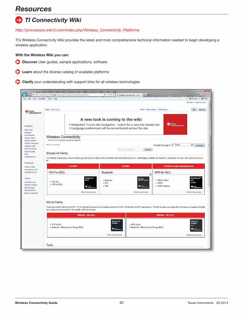
TI Connectivity Wiki ......................................................................... 62
TI Worldwide Technical Support ...................................................... 63
Wireless Connectivity Guide
Table of Contents
With the industry’s broadest wireless connectivity portfolio TI offers cost-effective, low-power solutions for short-range, long-range, mesh and IP networks, as well as personal area networks and more in the Internet of Things. TI SimpleLink™ solutions leverage more than a decade of wireless expertise and are designed to enable easier and faster development of RF applications. The SimpleLink portfolio supports technololgies: Wi-Fi®, Bluetooth®, Bluetooth low energy, ANT™, ZigBee® PRO, IEEE 802.15.4, ZigBee RF4CE, NFC/RFID, 6LoWPAN and PurePath™ Wireless audio, GPS as well as a selection of RF ICs and proprietary protocols for the Sub-1 GHz and 2.4 GHz frequency bands. TI provides an ecosystem of support such as development tools, technical documentation, reference designs, application samples, customer support and services from the Texas Instruments Design Network and university programs.
Getting started: Which wireless connectivity technology is right for your design
Finding the best connectivity fit for your application or system is a must and can be daunting. Below are two basic considerations – Maximum throughput and power source. For more information on how to get started, go to www.ti.com/wirelessconnectivity and learn more.
The right wireless connectivity solution
Whatever type of wireless technology you need for your next Internet of Things (IoT) designs, TI can help you find the right one for your application.
With the industry’s broadest wireless connectivity portfolio, TI supports more than a dozen wireless technologies for:• 802.15.4standards-basedmesh and IP networks• Personalareanetworks• ProprietaryRFsub-1GHz• ProprietaryRF2.4GHz• RFID/NFC• GPS
Connecting to the Internet of Things and more
Analysts estimate that the IoT is quickly growing with the expectation of 50 billion connected devices by 2020. TI is connecting the IoT now with the industry’s broadest portfolio of embedded wireless connectivity technologies, microcontrollers, processors and analog solutions. Examples of how IoT-ready connectivity is used:
SimpleLink self-contained solutions were designed to simplify wireless development and certification by minimizing the amount of RF expertise you need to wirelessly enable a wide range of applications. TI offers SimpleLink solutions for multiple wireless technologies including Wi-Fi®, ZigBee®, 6LoWPAN, ANT™ and GPS with an expanding portfolio to come.
Wireless solutions optimized for TI’s embedded processing portfolio
Decrease your development time with TI’s wireless technologies pre-integration and TI Embedded Processing solutions.
Our connectivity solutions are designed for the industry’s broadest embedded processing portfolio – from high-performance processors to low power MCUs.
Resources that make development easyOur solutions are paired with resources that make development fast and easy and reduce time-to-market.
TI’s out-of-the-box development tools will get you quickly started. Through TI you’ll have access to a broad variety of cost-effective development tools, reference designs and supporting application and design notes.
Get answers to your design questions from the TI design experts through our interactive online E2E™ community.
If you need help to speed up your application development, TI has an extensive network of third parties to help accelerate your design. The network consists of recommended companies, RF consultants, and independent design houses that provide a series of hardware module products and design services.
Wi-Fi IEEE 802.11 a/b/g/nWi-Fi continues to effectively penetrate the wireless market with an installed base of over 3.5B units with an annual shipment rate exceeding a billion units. Nine out of 10 Americans surveyed in a consumer poll said they would rather do without Starbucks for a year than give up their Wi-Fi connection! It is easy to see how the Internet of Things (IoT) is expected to grow to 50 billion connected devices by 2020.
Application areas•Medicaldevicesandremotepatient
monitoring• Consumerdevices(tablets,e-books,
media players), web browsing, Internet connectivity, and streaming multimedia
• Industrialandhomeautomation,remote monitoring, controlling, data-logging and diagnostics
How does Wi-Fi technology work?Wi-Fi networks use radio technologies based on the IEEE 802.11a, 802.11b, 802.11g and 802.11n to provide secure, reliable, fast wireless connectivity. Wi-Fi networks operate in the unlicensed 2.4- and/or 5-GHz radio bands at rates of 54 Mbps or greater. They can provide real-world performance similar to the basic 10BaseT wired Ethernet networks. For more information on Wi-Fi technology, visit www.wi-fi.org.
Why TI Wi-Fi?Texas Instruments is the world’s leading supplier of Wi-Fi products for portable, battery-powered products
leveraging nearly a decade of experience and eight generations of products which are optimized for the needs of personal technology and handheld products for the IoT. TI is also the market leader in combined wireless products such as the pre-certified, preWiLink™ 8 module (single-chip Wi-Fi/Bluetooth®/Bluetooth low energy device) which further solve issues such as coexistence, antenna sharing in size-constrained devices, cost and power consumption.
TI enables simple Wi-Fi connectivity with the self-contained SimpleLink™ CC3000, which allows very short design cycles by eliminating the need for extensive RF and Wi-Fi expertise.
Easy embedded Wi-Fi Internet-on-a-chip™ solutions for the Internet of ThingsCC3100/CC3200
Learn more at: www.ti.com/simplelinkwifi
TI makes connectivity even easier with the next-generation SimpleLink Wi-Fi solutions. The product family features Internet-on-a-chip solutions to solve industry challenges in designing a broad array of embedded Internet of Things (IoT) applications. The plat-forms enable:
Two options are available, both pin-to-pin compatible.
CC3100 Wireless Network ProcessorThe CC3100 device is a Wi-Fi, self-contained network processor with on-chip web server and embedded TCP/IP stack that connects easily to any low-cost and low-power microcontroller (MCU) such as the MSP430F552, thanks to a simple UART or SPI driver and host memory footprint as low as 7kB of code to reside on the MCU. Hardware design is made easy for space-constrained boards with a small 64-pin 9×9-mm QFN package. Certified modules are coming soon.
CC3200 Wireless MCUThe SimpleLink Wi-Fi CC3200 solutionThe industry’s first Wi-Fi wireless mi-crocontroller with user-dedicated MCU capitalizes on the CC3100 benefits and integrates a high-performance 80-MHz ARM® Cortex®-M4 MCU and peripherals. Developers can fully ac-cess the MCU portion with 200kB of application code available fully inde-pendent from the Wi-Fi processing. The peripheral set includes parallel
Get started with development tools• Bothdevicesaresupportedwithlow-costdevelopmentboardsandbyasoftware
development kit (SDK) including software drivers, sample applications, API guide, user documentation and a world-class support E2E™ community.
camera, I2S audio, SDMMC, ADC, SPI, UART, I2C, PWM, I/Os, built-in power management and RTC enabling many MCU embedded applications to con-nect to the cloud. Certified modules will be available.
2.4-GHz Wi-Fi + Bluetooth®/Bluetooth low energy pre-integrated modules
WL1801, WL1805, WL1831, WL1835
Learn more at: www.ti.com/wilink8
OverviewTI’s newest WiLink 8 module family enables FCC/IC/ETSI-compliant and fully integrated Wi-Fi and Bluetooth technology solutions for the Internet of Things with high throughput and ex-tended range. WiLink 8 solutions provide certified Wi-Fi and Bluetooth/Bluetooth low energy co-existence in a power-optimized design.
WiLink 8 is provided as certified modules by TI to reduce development time, lower manufacturing costs, save board space and minimize RF expertise required. Additionally, Linux™ and Android™ drivers for Wi-Fi and Bluetooth are pre-integrated with software development kits for TI’s AM335x and other Sitara™ microprocessors.
Key features and benefits• High-performanceWi-Fi 802.11 b/g/n 2.4-GHz Radio/
Baseband/MAC 20- and 40-MHz channels 2×2 MIMO (2.4 GHz) Up to 110 Mbps (UDP) of
throughput MRC for extended range of 1.4×
(2.4 GHz) Station and soft access point – Wi-Fi direct multi-channel
multi-role Personal and enterprise security Linux™ and Android™ drivers• Dual-modeBluetooth Bluetooth and Bluetooth low energy
(BT 4.0 compliant) Wi-Fi/Bluetooth single antenna
co-existence• Built-inpowermanagement• Advancedlow-powermodes• Hostinterfaces SDIO for Wi-Fi and UART for
ZigBee/IEEE 802.15.4ZigBee is a standards-based technology for remote monitoring, control and sensor network applications. The ZigBee standard was created to address the need for a cost-effective, standards-based wireless networking solution that supports low data-rates, low-power consumption, security, and reliability.
ZigBee supports self-healing mesh networking which is a decentralized network topology very similar to the Internet. It allows nodes to find new routes throughout the network if one route fails, making ZigBee a robust wireless solution.
Application areasA technology specifically targeted for wireless sensor networks, ZigBee 802.15.4 can be used in any monitoring and control application that requires a wireless link. The primary target markets are:
• Home,buildingandindustrialautomation
• SmartwirelesslightingcontrolandLED bulbs
• Homecontrol/security
• Medical/patientmonitoring
• Logisticsandassettracking
• SensornetworksandactiveRFID
• Advancedmetering/smartenergy
• Commercialbuildingautomation
• Energyharvesting
Why TI ZigBee?Texas Instruments is a founding member of the ZigBee Board of Directors. Unlike other hardware suppliers that outsource their ZigBee stack development, our software engineering team delivers golden
unit certified platforms which are the benchmark for other developer companies to test against. TI is the lead technical editor for the next generation IP based protocol stack. TI’s ZigBee solutions include:
• Cortex®-M3 based System-on-Chip (SoC) is targeted for dual stack SE and HA applications offering hardware security acceleration for fast commissioning.
• TIprovidescompleteandfreesoftware solution on various platforms (8051 and Cortex-M3 SoCs, ultra-low power MSP430™)
• TheCC2538ARM® Cortex-M3 SoC is the industry’s first 512-kB Flash device with enough on-chip memory to support onboard over-the-air download.
• TheZigBeesecond-generationCC2530 system-on-chip (SoC) is a ZigBee golden unit that is targeted for low-power applications and small-form-factor designs.
• ByrunningtheCC2530asaZigBeeNetwork Processor, it will run the ZigBee stack and handle all the network processing, offloading a separate host processor that runs the main application. The host processor communicates with the CC2530 over a serial interface. This partitioning option allows the designer to keep the ZigBee application profile and any other applications on the main processor.
• Thesecond-generationCC2520IEEE 802.15.4 transceiver can be used with the MSP430 MCU and Tiva™ suite of ARM Cortex-M3 technology. It is recommended for designers who want additional Flash and RAM.
SoC
small footprint, high
integration, low cost
Co-processor
flexible, easy to use and
reduced time to market
Dual-chip
ultra-low power or
high performance
Co
mp
lete
Zig
Be
eS
olu
tio
ns
Application CC2530 CC2538or Any MCU ( ™, ™)MSP430 Tiva
Any MPU ( ™)Sitara
MSP430
Protocol
stack
CC253x-based coprocessors
with UART/SPI/USB interface:
Three paths to ZigBee• Stack and application profile
OverviewThe world of wireless lighting control has seen a dramatic shift from custom or proprietary lighting solution as efficient and low cost solutions have been introduced to the general market. Consumers recognize the value of convenience, security, and comfort that wireless devices bring to the home or office. The barrier to these systems in the past has been that most product manufacturers do not provide a system that allows interoperability among different lighting control vendors.
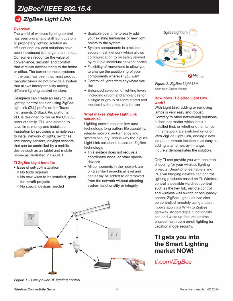
Designers can create an easy to use lighting control solution using ZigBee light link (ZLL) profile on the Texas Instruments Z-Stack Pro platform. ZLL is designed to run on the CC2530 product family. ZLL was created to save time, money and installation frustration by providing a simple easy to install network of lights, switches, occupancy sensors, daylight sensors that can be controlled by a mobile device such as an tablet and mobile phone as illustrated in Figure 1.
TI ZigBee Light benefits• Easeofset-up/installation No tools required No new wires to be installed, great
for retrofit projects No special devices needed
• Scalableovertimetoeasilyaddyour existing luminaries or new light points to the system
• Systemcomponentsinareliablesecure mesh network which allows communication to be safely relayed by multiple individual network nodes
• Flexibilityofmovementtoallowyouto change the positioning of your components wherever you want
• Controloflightsfromanywhereyoulike
• Enhancedselectionoflightinglevels(including on/off) and ambiances for a single or group of lights stored and recalled by the press of a button
What makes ZigBee Light Link valuable?Lighting control requires low cost technology, long battery life capability, reliable network performance and system security. This is why the ZigBee Light Link solution is based on ZigBee technology.• Thissystemdoesnotrequirea
coordinator node, or other special devices
• Allcomponentsinthenetworkareon a similar hierarchical level and can easily be added to or removed from the network without affecting system functionality or integrity
ZigBee®/IEEE 802.15.4
ZigBee Light Link
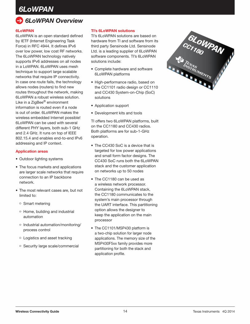
How does TI ZigBee Light Link work?With Light Link, adding or removing lamps is very easy and robust. Contrary to other networking solutions, it does not matter which lamp is installed first, or whether other lamps in the network are switched on or off. With ZigBee Light Link, adding a new lamp at a remote location is as easy as adding a lamp nearby in range. Figure 2 demonstrates the solution.
Only TI can provide you with one stop shopping for your wireless lighting projects. Smart phones, tablets and PCs via bridging devices can control lighting products based on TI. Wireless control is possible via direct control such as the key fob, remote control and wireless wall switch or occupancy sensor. ZigBee Light Link can also be controlled remotely using a tablet mobile app via a Wi-Fi to ZigBee gateway. Added digital functionality can add wake up features or time phased multi room on/off lighting for vacation mode security.
TI gets you into the Smart Lighting market NOW!
ti.com/ZigBee
Figure 1 – Low-power RF lighting control
Figure 2. ZigBee Light Link Courtesy of ZigBee Alliance
The CC2538 is a cost-effective, low-power, and full System-on-Chip (SoC) solution specifically tailored to IEEE 802.15.4 point-to-point, star, and ZigBee PRO mesh network advanced applications as well as ZigBee IP Smart Energy 2.0 applications and 6LoWPAN products.
The CC2538 combines a fully integrat-ed high-performance RF transceiver with an industry-standard enhanced Cortex®-M3 MCU, Flash, RAM and other powerful supporting features and peripherals.
The CC2538 comes in multiple memory and feature options, among them 256KB/512KB Flash memory, 16KB/32KB RAM memory and multiple security features such as AES engine with 128-, 192-, 256-bit key support and Public Key Accelerator ECC and RSA-2048.
Key features• Futureproofmemorysizes Up to 512 KB TSMC Flash to
enable on-chip OTA Up to 32 KB RAM (16 KB with
retention) to comfortably implement ZigBee IP routers
• Lower-powerIEEE802.15.4radio 20 mA in Rx 24 mA in Tx @ 0 dBm• PowerfulMCUsystem 1.2 µA sleep current with RTC with
120 µs wake up for long battery life Robust and proven power manage-
ment system• Capablesecuritycorereadyfor
ZigBee SE 2.0: AES engine with 128, 192, 256-bit
key support• CCM,GCM,CTR,CBC-MAC,ECB
modes of operation• SHA-256hashfunction• Securekeystoragememory• Highthroughput Public key accelerator• ECCandRSA-2048• Sidechannelattackprotectionagainst
The CC2520 is TI’s second generation ZigBee/IEEE 802.15.4 RF transceiver for the 2.4-GHz unlicensed ISM band. This chip enables industrial-grade applications by offering state-of-the-art noise immunity, excellent link budget, operationupto125°Candlow-voltage operation.
In addition, the CC2520 provides extensive hardware support for packet handling, data buffering, burst transmissions, data encryption, data authentication, clear channel assessment, link quality indication and packet timing information. These features reduce the load on the host controller.
The CC2530 is a cost-effective, low-power, and true System-on-Chip (SoC) solution specifically tailored to IEEE 802.15.4 point-to-point and star or ZigBee PRO mesh network applications.
The CC2530 comes in four different versions: CC2530-F32/64/128/256, with 32/64/128/256-KB Flash memory respectively, and combines a fully integrated high-performance RF transceiver with an industry-standard enhanced 8051 MCU, 8-KB RAM and other powerful supporting features and peripherals.
Key features• Upto256-KBFlashwith20Kerase
cycles to support over-the-air updates, large applications
• 8-KBRAMformorecomplex applications and ZigBee profiles
• Programmableoutputpower upto+4.5dBm
• Lessthan1-µAcurrent consumption in power down with sleep timer running
• Includespowerfuladdressrecogni-tion and packet processing engine
Benefits• SupportsZigBeePRO,ZigBee
RF4CE, 6LoWPAN, and all 802.15.4-based solutions
•Excellentreceiversensitivityand programmable output power
•VerylowcurrentconsumptioninRX, TX,andmultiplelow-powermodesensure long battery lifetime
• Best-in-classselectivityandblocking performance, with lowest packet error rate. Suited for battery applications.
The CC2531 is a USB-enabled SoC solution for IEEE 802.15.4, ZigBee PRO and RF4CE applications which enables USB dongles or USB upgrad-able network nodes to be built with low total bill-of-material costs. The CC2531 combines the performance of a leading RF transceiver with an industry-standard enhanced 8051 MCU, in-system programmable Flash memory, 8-KB RAM, and many other powerful features. Combined with the golden-unit-status (ZigBee PRO) from TI, the CC2531 provides a robust and complete ZigBee PRO dongle for firmware upgradable network node.
SECURITY & ALARMSensors can use lighting network for visual alarms in addition to sound
MOTION DETECTORUsed by alarm & lighting systems
HEATING & AIR CONDITIONINGWireless temperature sensors to maintain ideal temperature while lowering energy cost
ACCESS CONTROLKey fob can be used to lock door, turn on alarm and turn off lights
ENVIRONMENTAL MONITORINGWireless sensors for temperature, humidity & pressure minimize water usage & energy cost
REMOTE CONTROL
AUTOMATIC NOTIFICATIONUse gateway to GSM or other standard to be notified of alterations directly to a handset
LIGHTING CONTROLLight schemes to dim or turn on/off large number of lights
WINDOW CONTROLLight sensor and remote controls can be used to control the blinds
DSL MODEMUse gateway to Internet for monitor & control of home network
SECURITY & ALARMSensors can use lighting network for visual alarms in addition to sound
REMOTE CONTROL
ZigBee®/IEEE 802.15.4
Z-Stack™ – ZigBee® Protocol Stack
Z-Stack™ – TI’s industry-leading ZigBee protocol stackZ-Stack is TI’s protocol stack for a growing portfolio of IEEE 802.15.4 products and platforms. Z-Stack is a certified ZigBee-Compliant Platform for the ZigBee 2012 specifications on the C2538 System-on-Chip (SoC), CC2530SoCandMSP430+CC2520transceiver. Z-Stack supports the Smart Energy, Home Automation, Light Link, Building Automation and Health Care application profiles. The latest ZigBee PRO stack is downloadable from the TI web site without any royalty charge.
Key features• AfullycompliantZigBeePROfeature
set on the CC2530 and CC2538 family of SoCs and an extensive family of MSP430™ microcontrollers coupled with the CC2520 transceiver
• Arangeofsampleapplicationsincluding support for the ZigBee Smart Energy, ZigBee Home Automation and ZigBee Light Link Profiles
CC2591 (www.ti.com/cc2591) and CC2590 (www.ti.com/cc2590), the latest RF front ends which support regionalrequirementsfor+20dBmand+14dBmtransmitpowerandimproved receive sensitivity
Benefits• GoldenUnitZigBeePROsoftware
stack: deployed in millions of systems worldwide today
• OverTheAir(OTA)featureallowsfuture updates for your deployed hardware
• Abroadrangeofcertifiedsample applications reduce your development costs
• Flexiblearchitecturechoices
Application areasZigBee 802.15.4 can be used in anymonitoring and control application that requires a wireless link:• Commercialandresidentiallighting• Home,buildingandindustrial
6LoWPAN6LoWPAN is an open standard defined by IETF (Internet Engineering Task Force) in RFC 4944. It defines IPv6 over low power, low cost RF networks. The 6LoWPAN technology natively supports IPv6 addresses on all nodes in a LoWPAN. 6LoWPAN uses mesh technique to support large scalable networks that require IP connectivity. In case one route fails, the technology allows nodes (routers) to find new routes throughout the network, making 6LoWPAN a robust wireless solution. Like in a ZigBee® environment information is routed even if a node is out of order. 6LoWPAN makes the wireless embedded Internet possible! 6LoWPAN can be used with several different PHY layers, both sub-1 GHz and 2.4 GHz. It runs on top of IEEE 802.15.4 and enables end-to-end IPv6 addressing and IP context.
Application areas
•Outdoorlightingsystems
• Thefocusmarketsandapplicationsare larger scale networks that require connection to an IP backbone network.
• Themostrelevantcasesare,butnotlimited to:
Smart metering
Home, building and industrial automation
Industrial automation/monitoring/process control
Logistics and asset tracking
Security large scale/commercial
TI’s 6LoWPAN solutionsTI’s 6LoWPAN solutions are based on hardware from TI and software from its third party Sensinode Ltd. Sensinode Ltd. is a leading supplier of 6LoWPAN software components. TI’s 6LoWPAN solutions include:
• Completehardwareandsoftware6LoWPAN platforms
• High-performanceradio,basedonthe CC1101 radio design or CC1110 and CC430 System-on-Chip (SoC)solutions
• Applicationsupport
• Developmentkitsandtools
TI offers two 6LoWPAN platforms, built on the CC1180 and CC430 radios. Both platforms are for sub-1-GHz operation.
• TheCC430SoCisadevicethatistargeted for low power applications and small form factor designs. The CC430 SoC runs both the 6LoWPAN stack and the customer application on networks up to 50 nodes
• TheCC1180canbeusedasa wireless network processor. Containing the 6LoWPAN stack, the CC1180 communicates to the system’s main processor through the UART interface. This partitioning option allows the designer to keep the application on the main processor
• The CC1101/MSP430 platform is a two-chip solution for larger node applications. The memory size of the MSP430F5xx family provides more partitioning for both the stack and application profile.
The CC1180 is a cost effective, low power, sub-1-GHz network proces-sor that provides wireless 6LoWPAN functionality for system designers that want to connect their end products to the Internet using standards based IPV6 technology. The CC1180 is a preloaded version of the CC1110F32 SOC, where the TI third party Sensinode’s 6LoWPAN stack. Nanostack 2.0 Light runs on the CC1180 Network processor. The application controlling the network processor runs on an external host microcontroller. The CC1180 network processor handles all the timing critical and processing intensive 6LoWPAN protocol tasks and leaves the applica-tion microcontroller free to handle.
Key features
• EasyIntegrationof6LoWPANwithmesh support into any design
• Compactstack(around20k) optimized for sensor applications
• UARTinterfacetoalmostanymicro-controller running the application
• StandardIPsocketprogramming: Supports updating of the NanoStack 2.0 Lite 6LOWPAN stack using Sensinode NanoBoot API
Benefits
• Integratedhardwaredesignshortens time to market by 25%
• Embeddedstackwithsimplesampleapplications reduce firmware development by up to 50%
• Compactradioreferencedesign makes it ideal for small form factor end devices and sensors
• Lowcurrentconsumptionoptimizedfor sleeping end nodes and battery operated devices
BluetoothBluetooth wireless technology is one of the most prominent short-range communications technologies with an installed base of more than three billion units. Bluetooth is intended to replace the cables connecting portable and/or fixed devices while maintaining high levels of security, low power and low cost. A fundamental strength of Bluetooth is the ability to simultaneously handle data and voice transmissions. Bluetooth is designed to have very low power consumption by allowing radios to be powered down when inactive. The Bluetooth specification defines a uniform structure with global acceptance to ensure interoperability of any Bluetooth-enabled device.
How does Bluetooth technology work?Bluetooth technology operates in the unlicensed industrial, scientific and medical (ISM) band at 2.4 to 2.485 GHz, which is available and unlicensed in most countries. Bluetooth uses a spread spectrum, frequency hopping, full-duplex signal which was designed to reduce interference between wireless technologies sharing the 2.4-GHz spectrum. Bluetooth tech-nology provides greater performance even when other technologies are being used along with Bluetooth technology. Information above cited from the Bluetooth SIG. For more information on Bluetooth technology, visit www.Bluetooth.com.
Why TI Bluetooth?TI is one of the leading semiconductor companies providing Bluetooth wireless technology for portable, battery-powered devices leveraging nearly a decade of experience and seven generations of products which are optimized for the needs of handheld products. TI is also the market leader in combined wireless products such as the WiLink™ 8 solution single-chip Wi-Fi®/Bluetooth/Bluetooth low energy device), CC2560 (Bluetooth), CC2564 (Bluetooth/
Bluetooth low energy), which further solve issues such as coexistence, antenna sharing in size-constrained devices, cost and power consumption.
Dual modeDual-mode Bluetooth low energy technology is available as a part of TI’s proven WiLink connectivity combo solutions. These solutions support Wi-Fi and dual-mode operations by providing classic Bluetooth technology capability along with Bluetooth low energy technology. The WiLink 8 module solution includes on-chip coexistence, which yields size, cost, performance and power advantages that ease customer development cycles. WiLink brings connectivity features to mainstream products such as smart phones, mobile Internet devices (MIDs), portable media players (PMPs), gaming devices and personal navigation devices (PNDs).
For longer range, higher throughput and ability to connect to any mobile phone or tablet on the market, TI also has a Bluetooth dual-mode solution, the CC2564. It is used for audio and data applications and supports Bluetooth and Bluetooth low energy, assisted audio (SBC encode/decode) or ANT™ running simultaneously.
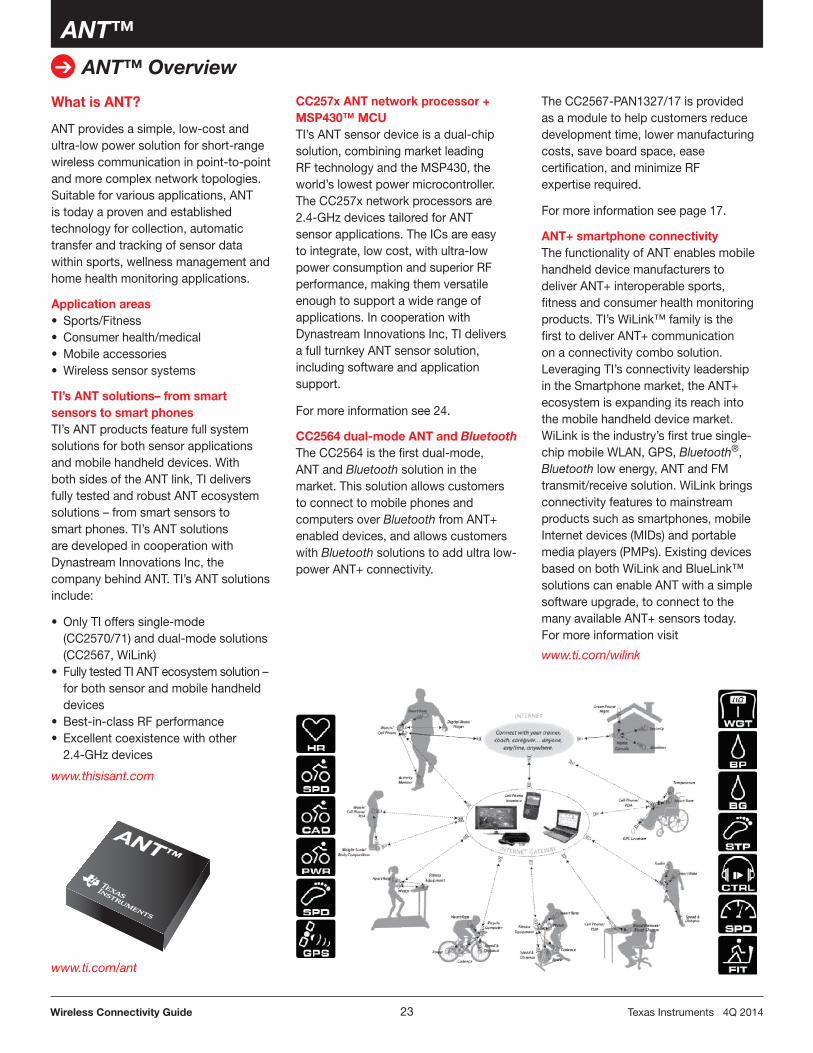
OverviewTI SimpleLink CC256x solutions are complete Bluetooth® BR/EDR/LE HCI or Bluetooth+Bluetooth Low Energy solutions that reduce design effort and enable fast time to market.
A royalty-free software Bluetooth stack available from TI is pre-integrat-ed with TI’s MSP430™ and ARM® Cortex®-M4 MCUs. The stack is also available for MFi solutions and on other MCUs. Examples of profiles sup-ported today include: serial port profile (SPP), human interface device (HID), A2DP (Advanced Audio Distribution Profile), AVRCP (Audio/Video Re-mote Control Profile) and several BLE profiles (profiles can vary based on the supported MCU).
In addition to software, reference designs are available with a low BOM cost. For example, TI’s Audio Sink solution uses the Bluetooth device for audio processing, an MSP430, audio DAC and USB charger. TI’s Audio Source solution is also available. For more information, visit TI Designs.
Benefits
• Best-in-classlinkbudgetextendsapplication range
• Simplifiedhardwareandsoftwaredevelopment
• Reduceddevelopmenttimeandcosts
• EnablessimultaneousoperationsofBluetooth with Bluetooth low energy
Dual-mode Bluetooth 4.1 controller available in certified modules with integrated audio capabilitiesCC2560, CC2564Learn more at: www.ti.com/bluetooth
Bluetooth® low energy technologyBluetooth low energy technology offers ultra-low power, state-of-the-art communication capabilities for consumer medical, mobile accessories, sports and wellness applications. Compared to classic Bluetooth capabilities, Bluetooth low energy is a connectionless protocol, which significantly reduces the amount of time the radio must be on. Requiring only a fraction of the power consumption of traditional Bluetooth technology, Bluetooth low energy can enable target applications to operate on a coin cell for more than a year.
TI’s Bluetooth low energy solutions – single mode and dual modeTI provides Bluetooth low energy single-mode solutions for sensor applications and dual-mode solutions for mobile handheld devices. With both sides of the link, TI delivers a fully tested and robust Bluetooth low energy ecosystem. TI also offers Dual mode Smart Ready solutions based on CC2564. This dual mode solution allows customers to create solutions that talk with both classic Bluetooth devices and Bluetooth low energy devices. TI’s Bluetooth low energy solutions include:
• TIprovidesbothsinglemodeanddual-mode Bluetooth low energy solutions
• Bothsidesofthelinktocreateafully tested Bluetooth low energy ecosystem – from smart sensors to smart phones
• LeadingRFperformanceupto–97dBm
• Excellentcoexistencewithother 2.4-GHz devices
• CC2540Systemonachipintegratedsolution (host and controller) and certified modules available
Single modeTI’s Bluetooth low energy solution for sensor applications includes the CC254x 2.4-GHz system-on-chip (SoC), TI protocol stack, profile software and application support. The CC254x is an ultra-low power, true one-chip integrated solution with controller, host and application on one device. It is a Flash-based and flexible device, with ultra-low power consumption, leading RF performance and excellent coexistence with other 2.4-GHz devices. Combined with the Bluetooth low energy protocol stack, the CC254x forms the market’s most flexible and cost-effective single-mode Bluetooth low energy solution.
For more information see page 20.
www.ti.com/bluetoothlowenergy
Bluetooth low energy for personal connectivity and health and fitness applications
The CC2540 is a cost-effective, low- power, true System-on-Chip (SoC) solution for single-mode Bluetooth low energy applications, including mobile accessories, sports and fitness, consumer health, sensors and actuators, remote controls, HID, proximity, and more. The CC2540 combines a 1-Mbps GFSK RF transceiver, offering superior range over the competition with a periph-eral rich 8051 MCU core. This highly integrated and low cost SoC, coupled with TI’s Bluetooth low energy stack, offers a true one-chip integrated solution.
Key features• Trueone-chipsingle-mode
Bluetooth low energy solution•OptimizedRFperformanceincluding
Tx/Rx power and selectivity• Extensiveperipheralsetincluding
USB, DMA, GPIO, USARTs, ADC, timers
• Flexiblelowpowermodestomaximize system lifetime when battery powered
Benefits• Versatilefeature-richdeviceallows
lowest cost system when integrating application and stack on single chip
• RFperformancemaximizescommunication range while simulta-neously minimizing the effect of interference sources
• Supportsrangeofapplicationsandreduces BOM cost through all-in-one SoC solution
• Ultra-lowaverage-powerconsump-tion in low-duty cycle systems
•Bluetooth low energy packet sniffer• Applicationprofiles,sample
applications, documentation and more
DGND_USB
USB_P
USB_N
DVDD_USB
P1_5
DVDD2
P1_1
P1_2
P1_3
P1_4
R301
C251
C261
C262 C253
C252
L251
L261
L252 L253
XTAL1
C221 C231
2LAT
X
C321
C331
C401
Optional 32-kHz Crystal(1)
CC2540DIE ATTACH PAD
RBIAS
AVDD4
AVDD1
AVDD2
RF_N
AVDD5
XOSC_Q1
XOSC_Q2
AVDD3
RF_P
0_1P
7_0P
6_0P
5_0P
4_0P
N_TES
ER
0_0P
1_0P
2_0P
3_0P
LP
UO
CD
1D
DV
D
6_1P
7_1P
0_2P
6D
DVA
1Q_K23
CS
OX/4_2P
2Q_K23
CS
OX/3_2P
2_2P
1_2P
Antenna(50 )
1
2
3
4
5
6
7
8
9
10
11 12 13 14 15 16 17 18 19 20
21
22
23
24
25
26
27
28
29
30
31323334353637383940
(1) 32-kHz crystal is mandatory when running the chip in low-power modes, except if the link layer is in the standbystate (Vol. 6 Part B Section 1.1 in [1]).NOTE: Different antenna alternatives will be provided as reference designs.
The CC2541 is a power-optimized true system-on-chip (SoC) solution for both low energy and proprietary 2.4-GHz applications. It enables robust network nodes to be built with low total bill-of-material costs. The CC2541 combines the excellent performance of a leading RF transceiver with an industry-standard enhanced 8051 MCU, in-system programmable Flash memory, 8-KB RAM, and many other powerful supporting features and peripherals. The CC2541 is highly suited for systems where ultra-low power consumption is required. This is specified by various operating modes. Short transition times between operating modes further enable low power consumption.The CC2541 is pin-compatible with the CC2540 in the 6-mm × 6-mm QFN-40 package, if the USB is not used on the CC2540 and the I2C/extra I/O is not used on the CC2541.
Key features• Trueone-chipsinglemode
Bluetooth low energy solution•OptimizedRFperformanceincluding
Tx/Rx power and selectivity• Extensiveperipheralsetincluding
I2C, DMA, GPIO, USARTs, ADC, timers
• Flexiblelowpowermodestomaximize system lifetime when battery powered
Benefits• Versatilefeature-richdeviceallows
lowest cost system when integrating application and stack on single chip
• RFperformancemaximizescommunication range while simulta-neously minimizing the effect of interference sources
• Supportsrangeofapplicationsandreduces BOM cost through all-in-one SoC solution
• Ultralowaverage-powerconsump-tion in low-duty cycle systems
Single-Mode Bluetooth® Low Energy System-on-ChipCC2541
Get samples, evaluation modules and application notes at: www.ti.com/sc/device/CC2541
General CharacteristicsParameter Min Typ Max Unit
Frequencyrange 2402 2480 MHz
Datarate — 1000 — kBaud
Operatingvoltage 2 — 3.6 V
Operatingtemperature –40 — 85 ºC
Outputpower –20 — 0 dBm
RX mode Receiversensitivity — –93 — dBm
Current consumptionCurrentconsumption,RX — 17.9 — mA
BLEStack – Bluetooth Low Energy Protocol Stack and Tools
TI’s Bluetooth® low energy (BLE) software development kit includes all necessary software to get started on the development of single-mode Bluetooth low energy applications using the CC2540/CC2541 system-on-chip. It includes object code with the Bluetooth low energy protocol stack, a sample project and applications with source code, and BTool, a Windows PC application for testing Bluetooth low energy applications. In addition to the software, the kit contains documentation, including a developer’s guide and Bluetooth low energy API guide.
Key features• Bluetooth specification version 4.0
compliant, single mode low energy host and controller sub-system. Stack certified as controller and host sub-systems.
• TI’s Bluetooth low energy solution includes System-on-Chip (SoC), in-house developed protocol stack, profile software and application support
• Profilesupportplannedbasedon specific profile specifications (attribute, PUID, proximity, remote and more)
• Bothmasterandslaverolesupport,multi-role support
ANT provides a simple, low-cost and ultra-low power solution for short-range wireless communication in point-to-point and more complex network topologies. Suitable for various applications, ANT is today a proven and established technology for collection, automatic transfer and tracking of sensor data within sports, wellness management and home health monitoring applications.
TI’s ANT solutions– from smart sensors to smart phonesTI’s ANT products feature full system solutions for both sensor applications and mobile handheld devices. With both sides of the ANT link, TI delivers fully tested and robust ANT ecosystem solutions – from smart sensors to smart phones. TI’s ANT solutions are developed in cooperation with Dynastream Innovations Inc, the company behind ANT. TI’s ANT solutions include:
• OnlyTIofferssingle-mode(CC2570/71) and dual-mode solutions (CC2567, WiLink)
• FullytestedTIANTecosystemsolution–for both sensor and mobile handheld devices
CC257x ANT network processor + MSP430™ MCUTI’s ANT sensor device is a dual-chip solution, combining market leading RF technology and the MSP430, the world’s lowest power microcontroller. The CC257x network processors are 2.4-GHz devices tailored for ANT sensor applications. The ICs are easy to integrate, low cost, with ultra-low power consumption and superior RF performance, making them versatile enough to support a wide range of applications. In cooperation with Dynastream Innovations Inc, TI delivers a full turnkey ANT sensor solution, including software and application support.
For more information see 24.
CC2564 dual-mode ANT and BluetoothThe CC2564 is the first dual-mode, ANT and Bluetooth solution in the market. This solution allows customers to connect to mobile phones and computers over BluetoothfromANT+enabled devices, and allows customers with Bluetooth solutions to add ultra low-powerANT+connectivity.
The CC2567-PAN1327/17 is provided as a module to help customers reduce development time, lower manufacturing costs, save board space, ease certification, and minimize RF expertise required.
For more information see page 17.
ANT+ smartphone connectivityThe functionality of ANT enables mobile handheld device manufacturers to deliverANT+interoperablesports,fitness and consumer health monitoring products. TI’s WiLink™ family is the firsttodeliverANT+communicationon a connectivity combo solution. Leveraging TI’s connectivity leadership intheSmartphonemarket,theANT+ecosystem is expanding its reach into the mobile handheld device market. WiLink is the industry’s first true single-chip mobile WLAN, GPS, Bluetooth®, Bluetooth low energy, ANT and FM transmit/receive solution. WiLink brings connectivity features to mainstream products such as smartphones, mobile Internet devices (MIDs) and portable media players (PMPs). Existing devices based on both WiLink and BlueLink™ solutions can enable ANT with a simple software upgrade, to connect to the manyavailableANT+sensorstoday. For more information visit
The CC2570 and CC2571 are ANT RF network processors that implement the easy-to-use, power-efficient ANT protocol. The CC2570 supports 1 ANT channel, while the CC2571 supports 8 ANT channels. The CC2570/71 can be connected to a host MCU (such as an MSP430™) through a UART or SPI serial interface and accessed through a set of API calls. The majority of the ANT protocol is built into the CC2570/71, including the ANT-FS file system functionality; only the applica-tion and profile layers need to reside on the host MCU, thus keeping host MCU memory requirements to a minimum.
Key features• ANTcompliantRFnetwork
processors• UART/SPIserialinterfaceto
easy-to-use API command set• ExcellentRFperformance(avg.
power and boosted output power)• Accuratefull-rangeRSSIfunction
suited for proximity• ANT-FSsupportBenefits• Easy-to-integrateintoANTproducts• Simple,accessibleserialinterfaceto
ANT-enable your product•Optimizedlowpowerforlongdevice
lifetime• HighresolutionRSSIproximity
pairingApplications• Sportsandfitnessequipment• Healthandmedicalequipment• Consumerhealthdevices• Consumerelectronics•WirelesssensornetworksDevelopment tools and software• ANTC7EK1CC257x
Development Kit• ANTware• IntegratedANT-FSreferencedesign• ANT-FSPChost• Embeddedreferencedesign
ANT™ Network ProcessorCC2570/CC2571
Get samples, evaluation modules and application notes at: www.ti.com/sc/device/CC2570
General CharacteristicsParameter Min Typ Max Unit
Operating conditionsFrequencyrange 2400 2507 MHz
Datarate — — kBaud
Operatingvoltage 2.0 — 3.6 V
Operatingtemperature –40 — 85 ºC
Outputpower –20 — 4 dBm
RX modeReceiversensitivity — –85.8 — dBm
Adjacentchannelrejection,+2MHz — 23 — dB
Adjacentchannelrejection,–2MHz — 23 — dB
Alternatechannelrejection,+4MHz — 39 — dB
Alternatechannelrejection,–4MHz — 39 — dB
Current consumptionCurrentconsumption,RX — 23.7 — mA
With the use of ZigBee® RF4CE radio frequency (RF) technology, remote control applications can operate non-line-of-sight and provide more advanced features based on bidirectional communication.ZigBee RF4CE advanced features for remote control applications:
• Nonline-of-sightcontrol
• Longerrange
• Richercommunication
• Increasedreliability
• Enhancedfeaturesandflexibility
• Interoperability
• Longerbatterylife
Application areas• Remotecontrols
• Set-topboxes,TVs,Blu-Rayplayers
• 3Dglasses
TI’s RF4CE solutions include:
• Matureandbroadportfolio(third-generation 802.15.4 SoC, RF4CE golden platform)
• Marketleadingperformance(best-in-class adjacent/alternate channel rejection, lowest system power consumption)
• Systemexpertise(HW,SW,toolsexperts, influential contributor to RF4CE standard)
•WWWsupport
RemoTI™ is a complete hardware and software solution for RF4CE remote control applications. TI has a mature and broad Portfolio (3rd generation 802.15.4 SoC and RF4CE golden platform):
• Software:Theindustry-leadingRF4CE-compliant stack feature the ZRC profile, a simple API, easy to understand sample application code and remote control reference design.
• Hardware:CC2533System-on-Chip (SoC) optimized for IEEE 802.15.4-based remote-control applications. The CC2533 enables single-chip remote controls to be built with lower power, higher reliability and lower bill-of material cost than alternative devices.
• Extensiveworldwidesupportandtools to ensure that development of ZigBee RF4CE-based products is simple, fast and can be completed at minimal cost.
TI’s industry-leading ZigBee RF4CE protocol stackTI’s ZigBee RF4CE-compliant protocol stack for remote control applications is built on TI’s well proven IEEE 802.15.4 compliant TIMAC. It offers a simple, easy-to-use, intuitive software architectural framework and all of the tools, documentation, and support
needed to build an RF4CE compliant product.
The stack is compliant with the ZigBee RF4CE specification and supports the ZRC (ZigBee Remote Control) profile and will support the upcoming ZID (ZigBee Input Device) profile.
The latest RemoTI stack is downloadable from the TI web site without any royalty charge.
Key features• CC2530,CC2531(USB),and
CC2533 RF SoC and CC259x RF front-end support
• Remotecontrolandproprietaryprofile support
• USBHIDclasssupportincludingkeyboard and consumer controls pages
The CC2533 is a cost-effective, low power, and true System-on-Chip (SoC) solution specifically tailored to IEEE 802.15.4/RF4CE applications. The CC2533 comes in three differ-ent versions: CC2533-F32/64 with 32/64-KB Flash memory and 4 KB of RAM and the CC2533-F96 with 96KB Flash and 6 KB of RAM. The CC2533 combines a fully integrated high-performance RF transceiver with an industry-standard enhanced 8051 MCU and powerful supporting features and peripherals.
Key features• Upto96-KBFlashwith20Kerase
cycles to support over-the-air updates, large applications
• Upto6-KBRAMforcomplexremote control applications
• Programmableoutputpowerupto+7dBm
• Lessthan1-μAcurrentconsumptionin power down with sleep timer running
• UART,I2C and SPI interfaces• IRgenerationandmodulation
PurePath™ Wireless AudioBy employing proprietary technology called PurePath Wireless, the CC85xx device family provides robust, high-quality, short-range 2.4-GHz wireless digital audio streaming in low-cost, single-chip solutions.
Two or more devices form a PurePath Wireless audio network. Great care has been taken to ensure that this audio network provides gap-less and robust audio streaming in varied environments and that it can coexist with existing wireless technologies in the crowded 2.4-GHz ISM band.
Most applications can be implemented without any software development and only require the CC85xx to be connected to an external audio source or sink (such as an audio codec, S/PDIF interface or class-D amplifier) and a few push buttons, switches or LED for human interaction. Advanced applications can interface a host processor or DSP directly to the CC85xx and directly stream audio and control most aspects of device and audio network operation.
Wireless headphone/headset design
•Cost-optimizeddesignwith100% TI content
•2×longerbatterylifethantypical headphone (22hr on 465mah battery)
•Wellsuitedforhigh-quality headphones/headsets
•DesignfilesavailablefromTI
The PurePath Wireless Configurator, a PC-based configuration tool, is used to set up the desired functionality and parameters of the target system and then produces firmware images that subsequently must be programmed into the embedded Flash memory of each CC85xx.
All devices in the CC85xx family interface seamlessly with the CC2590 RF range extender device to allow for even wider RF coverage and improved robustness in difficult environments.
Built-in wireless audio protocol with excellent robustness and coexistence through multiple techniques:
The CC8520 is used to build a lossless wireless audio link. One CC8520 acts as audio source and the other as audio sink. I2S data is taken as input on the audio source side, audio data is transmitted without loss to the audio sink which then outputs the I2S audio data.
Key features• Embeddedaudionetworkprotocol
with state-of-the art error correction and concealment techniques
The following product brief applies to the TC6000GN – a highly-integrated GPS module offered by GNS usingTexas Instruments’ SimpleLink™ GPS CC4000. The GNS TC6000GN module enables applications benefitting from precise time, location, and/or velocity data. This solution provides industry standard NMEA protocol data for accurate time, position, latitude, longitude, satellite status, course and speed. This solution provides industry standard NMEA protocol data for accurate time, position, latitude, longitude, satellite status, course and speed. Autonomous warm start and hotstart are enabled by on-board memory, improving start-up performance. A single GPIO is used to initiate a GPS fix (Push-to-fix), activating power management for active and deep sleep modes. Applications requiring high precision timing benefit from an independent programmable PPS generator. Further, the GPS driver and firmware is fully integrated into the module, greatly minimizing loading on the host CPU, and reducing system complexity. This allows GPS functionality to simply integrate with very small MCUs and MPUs. This solution is provided as a module to help customers reduce development time, lower manufacturing costs, save board space, and minimize RF and GPS expertise required.
The CC430 family of ultra-low-power microcontroller System-on-Chip (SoC), with integrated CC1101 RF transceiver core, consists of several devices featuring different sets of peripherals, targeted for a wide range of applications. The architecture, combined with up to seven low-power modes, is optimized to achieve extended battery life in portable measurement applications. The device features the powerful MSP430™ 16-bit RISC CPU, 16-bit registers, and constant generators that contribute to maximum code efficiency. The CC430 family provides a tight integration between the microcontroller core, its peripherals, software, and the RF transceiver, making these true SoC solutions easy to use as well as improving performance.
Development tools and software• eZ430-Chronoswirelesswatch
development tool• CC430F5137andCC430F6137
wireless development tools• CC430F6147wirelessdevelopment
tool (with DC-DC converter & LCD)
• SupportedbyIntegratedDevelop-ment Environments (IDEs) from TI and third parties including Code Composer Studio™ IDE (CCStudio) and IAR Embedded Workbench for MSP430 from IAR Systems.
The CC430 family of ultra-low-power microcontroller System-on-Chip (SoC),withintegratedCC1101RFtransceiver core, consists of several devices featuring different sets of peripherals, targeted for a wide range of applications. The architecture, combined with up to seven low-power modes, is optimized to achieve extended battery life in portable measurement applications. The device features the powerful MSP430™ 16-bit RISC CPU, 16-bit registers, and constant generators that contribute to maximum code efficiency. The CC430 family provides a tight integration between the microcontroller core, its peripherals, software, and the RF transceiver, making these true SoC solutions easy to use as well as improving performance.
Development Tools and Software• eZ430-Chronoswirelesswatch
development tool• CC430F5137andCC430F6137
wireless development tools• CC430F6147wireless developmenttool(withDC-DCconverter&LCD)
• SupportedbyIntegrated Development Environments (IDEs)fromTIandthirdpartiesincluding Code Composer Studio(CCS)andIAREmbeddedWorkbench for MSP430 from IAR Systems.
CC430F61xx/CC430F51xx
RF Microcontrollers Unified Clock System:
PMM:
Integrated CC1101 RF Transceiver
AES128 Encryption/DecryptionComparator B with 16-ch Analog MUX
Integrated solution provides low cost and high performanceThe CC110E is a highly integrated, multi-channel RF transceiver designed for low-power wireless applications in the 470-MHz and 950-MHz ISM bands.
Integrated solution provides low cost and high performanceThe CC1101 is a highly integrated, multi-channel RF transceiver designed for low-power wireless applications in the 315/433/868/915-MHz ISM bands. The CC1101 is an upgrade of the CC1100 transceiver with improvements for spurious response, close-in phase noise, input saturation level, output power ramping and extended frequency range.
Key features• Sub-1GHzFSK/GFSK/MSK/ASK/
OOK RF transceiver• 1.2to500-kBauddatarate• Low-power,lowsystemcost• Sleepcurrent:200nA• 90-µsPLLlocktime:240µsfromsleeptoRX/TX
•On-chipsupportforsyncworddetection, address check, flexible packet length and automatic CRC checking
• Separate64-ByteRXandTXdataFIFOs (enable burst mode data
transmission)• Suitableforsystemstargeting compliance with EN 300 200
(Europe) and FCC CFR Part 15 (U.S.)
Benefits• Fastdevelopmenttimeandlow system cost • Flexibleoptimizationofrangepower• Enablesuseofinexpensive
microcontroller• Enablesadaptivechannelselection
with increased robustness and coexistence of the wireless link • Smallsizesolution
Power consumptionCurrentconsumptionRX,868MHz — 14.7 — mA Inputwellabovesensitivitylimit
CurrentconsumptionTX ——
15.030.0
——
mAmA
0dBm12dBm
Currentconsumption,powerdown — <1 — µA
As part of the CC1101 family, the CC1101-Q1 (Transceiver), CC1131-Q1 (Receiver) and CC1151-Q1 (Transmitter) are available as automotive-qualified versions in accordance to AEC-Q100 Grade 1. All three parts come in a pin-to-pin and software-compatible 5×5-mm QFN-32 package and offer an extended temperature rangefrom–40to+125°C,tighterspecificationvaluesandguaranteedsensitivityvalues. See 36 for more information.
Integrated solution provides high performance. The CC1101-Q1 is a highly integrated, multichannel RF transceiver designed for low-power wireless applications in the 315/433/868/915-MHz ISM bands. The CC1101-Q1 is the automotive derivate of the CC1101 transceiver qualified in accordance to AEC-Q100 with extended electrical specification and extended temperature rangeupto+125°C.
Key features• Sub-1GHzFSK/GFSK/MSK/ASK/
OOK RF transceiver• 1.2to250-kBauddatarate• Low-power,lowsystemcost• Sleepcurrent:700nA• 90-μsPLLlocktime:240μsfrom sleeptoRX/TX
Radio, MCU and Flash all-in-one chipThe CC1110Fx family consists of three Systems-on-Chip designed for low-power and low-voltage wireless communication applications. With a 315/433/868/915-MHz radio transceiver, a single-cycle 8051 MCU, 8/16/32-kB Flash memory and additional peripherals, these unique all-in-one devices make it easier than ever to finish your design faster while offering numerous application possibilities.
Key features• High-performance,low-power8051
MCU core, typically with 8× the per-formance of a standard 8051
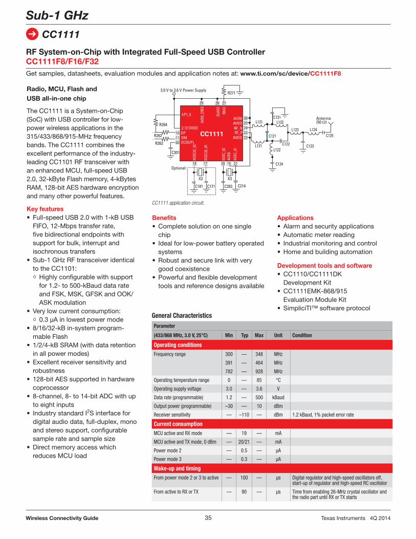
The CC1111 is a System-on-Chip (SoC) with USB controller for low-power wireless applications in the 315/433/868/915-MHz frequency bands. The CC1111 combines the excellent performance of the industry-leading CC1101 RF transceiver with an enhanced MCU, full-speed USB 2.0, 32-kByte Flash memory, 4-kBytes RAM, 128-bit AES hardware encryption and many other powerful features.
Key features• Full-speedUSB2.0with1-kBUSB
FIFO, 12-Mbps transfer rate, five bidirectional endpoints with support for bulk, interrupt and isochronous transfers
• Sub-1GHzRFtransceiveridenticalto the CC1101:
Highly configurable with support for 1.2- to 500-kBaud data rate and FSK, MSK, GFSK and OOK/ASK modulation
• Verylowcurrentconsumption: 0.3 µA in lowest power mode• 8/16/32-kBin-systemprogram-
mable Flash• 1/2/4-kBSRAM(withdataretention
in all power modes)• Excellentreceiversensitivityand
robustness• 128-bitAESsupportedinhardware
coprocessor• 8-channel,8-to14-bitADCwithup
to eight inputs• IndustrystandardI2S interface for
digital audio data, full-duplex, mono and stereo support, configurable sample rate and sample size
• Directmemoryaccesswhichreduces MCU load
RF System-on-Chip with Integrated Full-Speed USB Controller CC1111F8/F16/F32Get samples, datasheets, evaluation modules and application notes at: www.ti.com/sc/device/CC1111F8
Integrated solution provides high performance. The CC1131-Q1 is a highly integrated, multichannel RF receiver designed for low-power wireless applications in the 315/433/868/915-MHz ISM bands. The CC1131-Q1 is the receiver only derivate of the CC1101-Q1 transceiver qualified in accordance to AEC-Q100 with extended electrical specification and extended temperature rangeupto+125°C.
Key features• Sub-1GHzFSK/GFSK/MSK/ASK/
OOK RF receiver• 1.2-to250-kBauddatarate• Low-power,lowsystemcost• Sleepcurrent:700nA• 90-μsPLLlocktime:240μsfrom sleeptoRX
•On-chipsupportforsyncworddetection, address check, flexible packet length and automatic CRC checking
• 64-ByteRXdataFIFOs(enableburstmode data reception)
• Suitableforsystemstargetingcom-pliance with EN 300 200 (Europe) and FCC CFR Part 15 (U.S.)
Benefits• Fastdevelopmenttimeandlow
system cost• Flexibleoptimizationofrangepower• Enablesuseofinexpensive
microcontroller • Enablesadaptivechannelselection
with increased robustness and coexistence of the wireless link
• Easysystemscalingfromunidi-rectional to bidirectional systems through compatible device family
Integrated solution provides high performance. The CC1151-Q1 is a highly integrated, multichannel RF transmitter designed for low-power wireless applications in the 315/433/868/915-MHz ISM bands. The CC1151-Q1 is the transmitter only derivate of the CC1101-Q1 transceiver qualified in accordance to AEC-Q100 with extended electrical specification and extended temperaturerangeupto+125°C.
Key features• Sub-1GHzFSK/GFSK/MSK/ASK/
OOK RF transmitter• 1.2-to250-kBauddatarate• Low-power,lowsystemcost• Sleepcurrent:700nA• 90-μsPLLlocktime:240μsfrom sleeptoTX
•On-chipsupportforsyncwordinsertion, address insertion, flexible packet length and automatic CRC insertion
• 64-ByteTXdataFIFOs(enableburstmode data transmission)
• Suitableforsystemstargeting compliance with EN 300 200 (Europe) and FCC CFR Part 15 (U.S.)
Benefits• Fastdevelopmenttimeandlowsys-
tem cost• Flexibleoptimizationofrangepower• Enablesuseofinexpensive
microcontroller • Enablesadaptivechannelselection
with increased robustness and coex-istence of the wireless link
• Easysystemscalingfromunidirec-tional to bidirectional systems thru compatible device family
The CC1190 is range extender for the sub-1-GHz low-power RF transceivers and System-on-Chip (SoC) devices from Texas Instru-ments. The CC1190 integrates a power amplifier (PA), a low noise amplifier (LNA), switches, and RF matching for the design of high-performance wireless systems. The CC1190 increases the link budget by providing a power amplifier for increased output power, and an LNA with low noise figure for improved sensitivity. The CC1190 provides an efficient and easy-to-use range extender in a compact 4×4mm package.
Key features• Seamlessinterfacetosub-1-GHz
low-power RF devices from TI
• Upto27dBm(0.5W)outputpower
• 2.9dBLNAnoisefigureincludingswitch and external antenna match
• Fewexternalcomponents:theintegrated PA, LNA, switches, matching network and inductors improve system performance over typical discrete front end solutions
• HightransmitpowerefficiencyPAE=50% at 26 dBm output power
Benefits• Anintegratedfrontendreduces
development time by up to 70%
• UsingtheCC1190withevenasmall6dB increase in link budget doubles the range, making the CC1190 a great choice for remote monitoring
• Acompactreferencedesignreducesthe board space for a front end by up to 50%
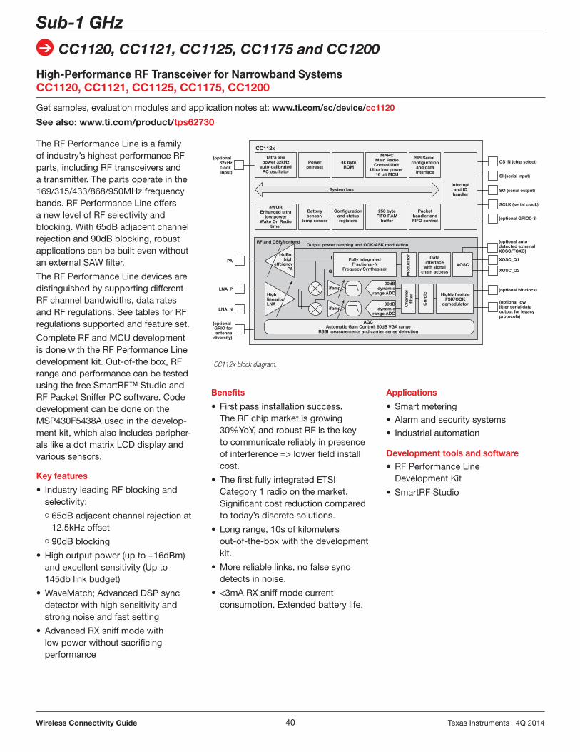
The RF Performance Line is a family of industry’s highest performance RF parts, including RF transceivers and a transmitter. The parts operate in the 169/315/433/868/950MHz frequency bands. RF Performance Line offers a new level of RF selectivity and blocking. With 65dB adjacent channel rejection and 90dB blocking, robust applications can be built even without an external SAW filter.
The RF Performance Line devices are distinguished by supporting different RF channel bandwidths, data rates and RF regulations. See tables for RF regulations supported and feature set.
Complete RF and MCU development is done with the RF Performance Line development kit. Out-of-the box, RF range and performance can be tested using the free SmartRF™ Studio and RF Packet Sniffer PC software. Code development can be done on the MSP430F5438A used in the develop-ment kit, which also includes peripher-als like a dot matrix LCD display and various sensors.
Key features
• IndustryleadingRFblockingandselectivity:
65dB adjacent channel rejection at 12.5kHz offset
90dB blocking
• Highoutputpower(upto+16dBm)and excellent sensitivity (Up to 145db link budget)
•WaveMatch;AdvancedDSPsyncdetector with high sensitivity and strong noise and fast setting
• AdvancedRXsniffmodewith low power without sacrificing performance
High-Performance RF Transceiver for Narrowband SystemsCC1120, CC1121, CC1125, CC1175, CC1200
Get samples, evaluation modules and application notes at: www.ti.com/sc/device/cc1120
See also: www.ti.com/product/tps62730
Benefits
• Firstpassinstallationsuccess.The RF chip market is growing 30%YoY, and robust RF is the key to communicate reliably in presence of interference => lower field install cost.
• ThefirstfullyintegratedETSICategory 1 radio on the market. Significant cost reduction compared to today’s discrete solutions.
• Longrange,10sofkilometersout-of-the-box with the development kit.
•Morereliablelinks,nofalsesyncdetects in noise.
• <3mARXsniffmodecurrentconsumption. Extended battery life.
Applications
• Smartmetering
• Alarmandsecuritysystems
• Industrialautomation
Development tools and software• RFPerformanceLine
Development Kit
• SmartRFStudio
CC112x block diagram.
CC112x
Ultra lowpower 32kHz
auto-calibratedRC oscillator
Poweron reset
4k byteROM
MARCMain Radio
Control Unit Ultra low power
16 bit MCU
SPI Serial configuration
and datainterface
Interruptand IOhandler
System bus
CS_N (chip select)
SI (serial input)
SO (serial output)
SCLK (serial clock)
(optional GPIO0-3)
eWOREnhanced ultra
low powerWake On Radio
timer
Batterysensor/
temp sensor
Configurationand statusregisters
256 byteFIFO RAM
buffer
Packethandler andFIFO control
(optional 32kHzclock
input)
PA
LNA_P
LNA_N
(optional GPIO forantenna
diversity)
RF and DSP frontend
14dBmhigh
effciencyPA
HighlinearityLNA
Output power ramping and OOK/ASK modulation
Fully integratedFractional-N
Frequecy Synthesizer
Mo
dul
ato
rC
hann
elfi
lter
Co
rdic
Datainterface
with signalchain access
XOSC
Highly flexibleFSK/OOK
demodulator
AGCAutomatic Gain Control, 60dB VGA range
RSSI measurements and carrier sense detection
I
Q
ifamp
ifamp
90dBdynamic
range ADC
90dBdynamic
range ADC
(optional autodetected externalXOSC/TCXO)
XOSC_Q1
XOSC_Q2
(optional bit clock)
(optional low jitter serial data output for legacyprotocols)
The RF Value Line is a family of low cost RF parts, including a transceiver, a receiver and a transmitter. The parts are pin, register and code compatible, and they can be used to migrate between 1-way and 2-way RF solutions using the same PCB for both options. The parts operate in the 315/433/868/915MHz bands. The RF Value Line is based on TI’s very popular CC1101 RF transceiver, and the devices have inherited the key benefits of this platform. This includes very flexible modulation formats and data rates to be compatible with almost any existing RF solution, advanced digital features and a vast pool of design resources with more than 50 application notes have been published on the platform.
To make RF development easier and more accessible an RF Booster-Pack for the MSP430 LaunchPad is also available. The new 430BOOST-CC110L RF BoosterPack includes ETSI-compliant and FCC-certified modules to help speed development time, reduce certification costs and eliminate barriers associated with the RF hardware design process.
Key features
• CC1101RFperformance•FlexibleRFmodulationformats
2-FSK, 4-FSK, GFSK and OOK, data rates from 0.6 to 600kbps
CC2543/44/45 is a family of 2.4GHz RF Value Line System-on-Chip (SoC) with MCU, 32KB Flash and 1/2KB RAM on a single die. They feature 2-Mbps data rate, 102dB link budget and <1µA sleep current with sleep timer running. The family members are distinguished by different number of general I/O pins, and CC2544 has a USB interface.
The CC2543-CC2544 Development Kit provides a complete hardware performance test platform and generic software development environment for 2.4-GHz RF proprietary applications. The kit includes two CC2543-based RF evaluation modules, one CC2544-based USB dongle, general purpose development boards (SmartRF05EB) for software and hardware prototyping, cables, antennas and documentation to get you up and running with the CC2543, CC2544, and CC2545 quickly and easily.
Complete RF and MCU development is done with the CC2543-CC2544 Development Kit. Out-of-the box, RF range and performance can be tested using the free SmartRF Studio. Code development can be done on embedded 8051 core used in the development kit, which also includes peripherals like a dot matrix LCD display and various other interfaces.
CC2543/44/45 is a family of 2.4GHz RFValueLineSystem-on-Chip(SoC)with MCU, 32kB flash and 1/2kB RAM on a single die. They feature 2Mbps data rate, 102dB link budget and <1uA sleep current with sleeptimer running. The family members are distinguished by different number of general I/O pins, and CC2544 has a USB interface.
The CC2543-CC2544 Development Kit provides a complete hardware performance test platform and generic software development environment for 2.4GHz RF proprietary applications. The kit includes two CC2543-based RF evaluation modules, one CC2544-based USB dongle, general purpose developmentboards(SmartRF05EB)for software and hardware prototyping, cables, antennas and documentation to get you up and running with the CC2543, CC2544, and CC2545 quickly and easily.
Complete RF and MCU development is done with the CC2543-CC2544 Development Kit. Out-of-the box, RF range and performance can be tested using the free SmartRF Studio. Code development can be done on embedded 8051 core used in the development kit, which also includes peripherals like a dot matrix LCD display and various other interfaces.
CC2590 and CC2591 are 2.4-GHz range extenders specially designed for all existing and future 2.4-GHz RF transceivers and System-on-Chip (SoC) solutions from TI. CC2590/CC2591 increase the link budget by providing a power amplifier for improved output power and an LNA with low noise figure for improved receiver sensitivity. They contain PA, LNA, switches, RF-matching, and balun for simple design of high-performance wireless applications.
The PaLFI – Passive Low-Frequency Interface TMS37157 enables short-range two way communication without the need of a battery by harvesting the RF energy transmitted from the base-station. It combines a Low-Frequency RFID Transponder with EEPROM memory and an SPI Interface to connect to a microcon-troller. The EEPROM memory is accessible via the LF and SPI interface without battery support. It is ideal for data-logging applications (configuration or updating a device without the need of a battery), for medical applications (non-battery operated bio-sensors) and as a method for recharging batteries while enabling two way communications. The TMS37157 can also be used in combination with active low power devices to wake up the active device in a defined read zone and thus conserve the battery life. Dependent on system parameters such as antenna sizes and base station power, the device wirelessly powers an MSP430 MCU at ranges up to 1.5 meter.
Key features• Lowfrequencyhalfduplex(HDX)
interface Special selective addressing
mode allows anti collision Up to 8 kbit/s LF uplink data rate• 3-wireSPIinterface• 1008bitEEPROM: 968-bit free available EEPROM
user memory 32-bit unique serial number 8-bit selective address Pages are irreversible lockable
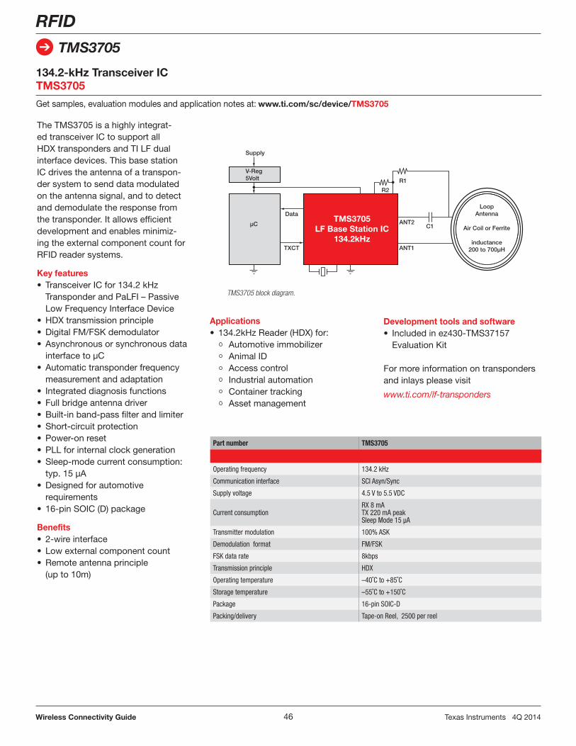
The TMS3705 is a highly integrat-ed transceiver IC to support all HDXtranspondersandTILFdualinterface devices. This base station IC drives the antenna of a transpon-der system to send data modulated on the antenna signal, and to detect and demodulate the response from the transponder. It allows efficient development and enables minimiz-ing the external component count for RFID reader systems.
Key features• TransceiverICfor134.2kHz
Transponder and PaLFI – Passive Low Frequency Interface Device
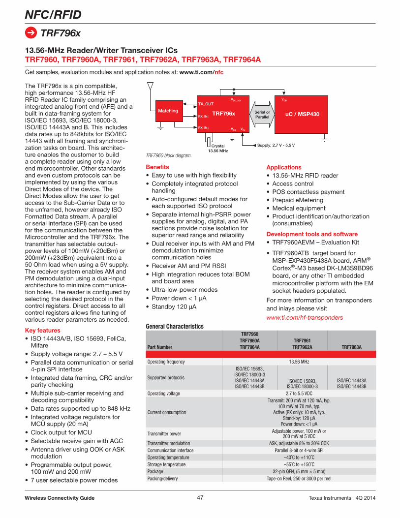
The TRF796x is a pin compatible, high performance 13.56-MHz HF RFID Reader IC family comprising an integrated analog front end (AFE) and a built in data-framing system for ISO/IEC 15693, ISO/IEC 18000-3, ISO/IEC 14443A and B. This includes data rates up to 848kbits for ISO/IEC 14443 with all framing and synchroni-zation tasks on board. This architec-ture enables the customer to build a complete reader using only a low end microcontroller. Other standards and even custom protocols can be implemented by using the various Direct Modes of the device. The Direct Modes allow the user to get access to the Sub-Carrier Data or to the unframed, however already ISO Formatted Data stream. A parallel or serial interface (SPI) can be used for the communication between the Microcontroller and the TRF796x. The transmitter has selectable output-powerlevelsof100mW(+20dBm)or200mW(+23dBm)equivalentintoa50 Ohm load when using a 5V supply. The receiver system enables AM and PM demodulation using a dual-input architecture to minimize communica-tion holes. The reader is configured by selecting the desired protocol in the control registers. Direct access to all control registers allows fine tuning of various reader parameters as needed.
The TRF7970A is the newest addition to the TRF796x HF Transceiver IC Family. TRF7970A supports Near Field Communication (NFC) Standards NFCIP-1 (ISO/IEC 18092) and NFCIP-2 (ISO/IEC 21481) which defines the selec-tion of any of the four possible commu-nication modes (NFC peer-to-peer, card emulation, proximity reader/writer – ISO 14443A/B, Mifare or FeliCa and Vicinity reader/writer – ISO 15693). Integrated encode, decode and data framing capability for data rates up to 848bps, wide supply voltage range support (2.7V – 5.5V), large FIFO buffer for RF communication, relevant NFC software stack libraries and an innovative RF field detector allow for easy development ef-forts and robust, cost effective designs. Finally, eight selectable power modes and ultra-low power operation enable the longest battery life in the industry. The devices also offer unparalleled flexibility via the various direct communication modes on the device to allow implemen-tations of custom protocols as well as other 13.56-MHz standards. The receiver system enables AM and PM demodula-tion using a dual-input architecture to maximize communication robustness.
Development tools and software• TRF7970AEVM evaluation kit• TRF7970ATBtargetboardfor MSP-EXP430F5529boardoranyotherTI embedded microcontroller platform with the EM socket headers populatedGeneral Characteristics
TI Embedded Processors – A perfect companion to our radios in wireless systemsMicrocontrollers are an integral part of all wireless connectivity systems, especially in low-power wireless solutions. From being the main applications and/or protocol processor to performing power management functions to coordinating communications, microcontrollers play a key role both in battery operated end nodes as well as host devices such as coordinators and routers. TI’s broad industry leading portfolio of embedded processors, from the ultra-low power MSP430™ microcontrollers to our high-performance Sitara™ portfolio and DSP products, ensures you have the choice of the right device for any wireless connectivity application.
TI recognizes the importance of embedded software in wireless connectivity solutions. Our embedded processors are supported by a wide variety of software stacks, including protocol and network solutions.
Finally we offer a comprehensive suite of development tools and online resources to make your wireless connectivity design robust, easy and fast.
TI Embedded Processors
Code Composer Studio™ IDE
16-Bit Ultra-LowPower MCUs
MSP430™
Microcontroller (MCU)
Embedded Processing Portfolio
• Up to 25 MHz• Up to 512 KB Flash• Up to 64 KB FRAM• Analog I/O, ADC• LCD, USB, RF
Measurement,Sensing, General
purpose
ARM®-Based Processor Digital Signal Processor (DSP)
32-BitReal-Time MCUs
C2000™
• 40 MHz to 300 MHz• Flash, RAM 16 KB to 512 KB• PWM, ADC, CAN, SPI, I2C
32-BitARM MCUs
Tiva™ C SeriesARM Cortex™-M4
• Up to 80 MHz• Flash 32 KB to 256 KB• USB OTG, CAN, ADC, PWM, SPI
The MSP430 family of ultra-low-power microcontrollers
MSP430 microcontrollers (MCUs) from Texas Instruments (TI) are 16-bit, RISC-based, mixed-signal processors designed for ultra-low power. Our MCUs offer the lowest power consumption and the perfect mix of integrated peripherals for thousands of applications – including yours. We also provide all of the hardware and software tools you need to get started today! Not only that, TI has a plethora of complementary components to meet your needs. Learn more today at ti.com/msp430. Visit www.ti.com/msp430 for a complete product portfolio and more information.
By making RF design easy, performance-rich and power-efficient, the MSP430 helps advance RF networking applications from RFID to Bluetooth®/Bluetooth low energy as well as proprietary protocols. These applications include, but are not limited to, industrial/building automation, asset tracking, industrial
MSP430 embedded software:
The MSP430 microcontroller supports several wireless connectivity protocol and networking software stacks with more options coming soon.
monitoring and tamper detection, alarm and security systems, sports/body monitoring, wireless keyboard/mouse products, wireless gaming accessories and automatic metering
infrastructure (AMI). The ultra-low power consumption of the MSP430 also enables energy harvesting applications with wireless systems.
Advanced peripherals• High-performanceanalog• Optimizedserialcommunications• Operateinlow-powermodesMinimize physical footprint and bill of materials• USB• LCDdrivers• Sigma-DeltaADCs
Scale your applications• 400+devices• Upto512KBFlashand64KBRAM• 25+packageoptions
Unlimited possibilities with TI• Datacollection• Wirelessconnectivity• Powersolutions
Now, let’s talk hardware! MSP430 MCUs are supported by a broad collection of hardware development tools for beginners as well as experienced engineers. Our tools range from low-cost development kits like the MSP430 LaunchPad Evaluation Kit to highly-integrated, application-specific platforms and target boards for integrating MSP430 into your designs.
Hardware support tools
One tool to rule them all. The MSP430 Flash Emulation Tool (MSP-FET430UIF) supports all MSP430 devices when paired with the appropriate target board.
BoosterPacks are plug-in modules for the LaunchPad, which enable customers to stack additional functionality such as wireless, capacitive touch and more.
Explore the ecosystem at www.ti.com/launchpad
Full-featured development kits
MSP430 LaunchPad and BoosterPack ecosystem
LaunchPad Evaluation Kits provide customers everything needed to get started.
Try it out with Energia for the simplified user experience! Learn more about this easy-to-use IDE at www.energia.nu/
MSP-TS430PM64
MSP-FET430UIFBundle availableMSP-FET430U64
MSP-EXP430F5529LPconnected to the CC3000-BOOST
Production programmer
The MSP-GANG can program up to eight identical MSP430 Flash or FRAM devices at the same time and allows the user to fully customize the process.
The MSP430 eZ430 development tools are the best way to get familiar with the MSP430 MCU and include all the software and hardwareneededtodevelopacompleteprojectandareavailableforaslittleas$20.MosteZ430toolsincludeaprogramminginterface that provides full debugging and programming capabilities for the detachable MSP430 target boards. For more information visit www.ti.com/ez430.
These innovative kits feature select MSP430 devices and include additional hardware components to take advantage of the high level of analog integration available for easy system evaluation and prototyping. These kits are ideal for learning the MSP430 architecture, testing the capabilities of available peripherals and include integrated headers for plugging in low-power RF modules (CCxxxxEMK).
TI’s Sitara processors based on the ARM9™ and ARM® Cortex®-A8/-A9 cores, in conjunction with TI’s Wi-Fi®/Bluetooth® connectivity options provide the right combination of performance, power and peripherals to meet any wireless application need. Drive down system cost, simplify design and expand connectivity of your current design all while maintaining software compatibility across TI’s ARM9 and ARM Cortex-A8/ -A9 processor portfolio.
Key features•Multipleoperatingfrequenciesfor
optimizing power vs. performance
• 3Dgraphicsacceleration,multiplepackaging options and temperature ranges
• TIconnectivitysolutions(Wi-Fi/Bluetooth) support
• High-bandwidthconnectivity peripherals such as Gigabit Ethernet,
DDR2/DDR3 interfaces, CAN, SATA 2.0 and USB 2.0
Part Number BeagleBoneBlack–BEAGLEBK AM335xStarterKit–TMDSSK3358 AM437xEVM–TMDXEVM437X
USB interface• Multipleserialports• Touch-screenLCDcontrollers• Industrialperipheralsupport
Portfolio
• Leverage TI’s extensive portfolio of embedded ARM devices to maximize your product’s changing needs
• Reuse of both software and hardware design across portfolio
• Fully pin-for-pin and software-compatible options across portfolio
Ease of Use
• Free and easy access Linux™ and Android™
• Application-specificand advanced development kits
• Third-partyRTOSecosystem
Development toolsThese full-featured development boards come complete with hardware, software and documentation and a wireless connectivity module to accelerate hardware/software development. Available from TI and distributors. Additional low-cost community-based boards can be obtained from numerous partners and distributors. www.ti.com/sitara
TI provides development tools that enable both software and hardware designers to quickly get up and running with wireless connectivity products. The general-purpose low-power RF development tools consist of three elements – the Evaluation Module, Evaluation Board and PC Tools:
Evaluation Module (EM)A small plug-in board with thecomplete reference design for the radiodevice, ensuring maximum performance.
Evaluation Board (EB)Contains sockets for the EM.Platform for testing theperformance of the radio andfor development of protoypesoftware.
PC ToolsConnect the EB to the PC anduse available tools to test,configure and debug softwarerunning on the chip.
There are several types of hardware development tools.
Development Kit (DK)
The DK contains all the hardware that is necessary to start development of an RF system. In most configurations, a development kit consists of two Evaluation Boards, two small RF modules, antennas and cables.
Mini Development Kit (DK-MINI)
Mini Development Kits are low-cost development kits that contain the basic hardware for prototyping and for developing simple demonstration applications. The kits can also be used for basic evaluation of the device.
Evaluation Module Kit (EMK)
The EMK contains two RF modules (EM) and antennas. The EMK can be ordered separately and can be used as add-ons to existing kits, compatible motherboards or other boards with matching connectors.
USB Dongles
Small form-factor dongles with the USB enabled System-on-Chip (SoC) and PCB antenna.
ZigBee® and ZigBee RF4CE Development Kits
The ZigBee Development Kit (ZDK) has all the features of a development kit, but contains additional nodes for experimenting with the mesh capabilities of ZigBee. The kit is preprogrammed with a ZigBee demo application, giving you ZigBee directly out of the box.
A specific ZigBee Network Processor (ZNP) kit demonstrates the concept with a CC2530 running the Z-Stack and a small MSP430 running the application code.
To get quickly up and running with ZigBee RF4CE, there’s a dedicated kit containing a fully functional remote controller, a receiver board with a multitude of connection options and a USB dongle for PC connectivity.
Bluetooth low energy Development KitsTI has made it easy for a fast and convenient development with Bluetooth Low Energy by the use of the CC2540DK-MINI. It contains a USB dongle and a key fob for rapid prototyping. Complete Evaluation Module Kits for CC2540 and CC2541 are also available.
Bluetooth low energy SensorTag Development KitThe award-winning SensorTag development kit, based on the CC2541 SoC, shortens the design time for Bluetooth application development from months to hours with no hardware or software expertise required. The over-the-air download feature provides the ability to update firmware from a central device like a smartphone, tablet or PC. The SensorTag has limitless possibilities in applications including health and fitness, educational tools, toys, remote controls and mobile phone accessories. Find out more at ti.com/tool/ cc2541dk-sensor.
TI University Program offers universities the industry’s broadest wireless connectivity portfolio, supporting more than a dozen different wireless technologies.
Add TI to your curriculum, contact: www.ti.com/univcontacts
What can I do with a DK?In most configurations, a development kit consists of two Evaluation Boards, two small RF modules, antennas and cables. When the RF modules are connected to the Evaluation Board, it is possible to control the radio from the PC using SmartRF™ Studio. Most of the development kits also come preprogrammed with a Packet Error Rate test application, which makes it easy to perform practical range testing with the radios. In addition, the development kits are flexible platforms and it is easy to connect your own peripherals and controllers to break-out pins on the boards. The development kit would also serve as a known good platform during test and verification of your own system. For development kits with system-on-chips (SoC), the evaluation boards make it possible to debug and program the chip with no additional hardware. The kit also gives access to useful user interfaces for testing of the various peripherals and capabilities of the SoC. The hardware in the kit can also be used as a packet sniffer.
What is the purpose of the EMK?The Evaluation Module (EM) is exactly the same piece of hardware that is being used in characterization of the radio, and you will get datasheet performance from these boards. The EMK can be ordered separately and can be used as add-ons to existing kits, compatible motherboards or other boards with matching connectors. The modules are equipped with two 2×10 sockets from Samtec (SFM-110-02-SM-D-A-K-TR) matched with headers from Samtec (TFM-110-02-SM-D-A-K-TR).
Why do I need the Evaluation Board?The Evaluation Board (EB) is a flexible test and development platform. It makes it easy to perform basic functional RF tests. For example:• ConnecttheEBtoyourhardwareto
test your own RF design (running tests from SmartRF Studio)
•UseSmartRFStudio+EB+EMtosend packets that are received by your own system
•Useyourownsystemtosendpacketsand receive the packets using SmartRFStudio+EB+EM
Thus, you can easily verify the behavior of either your own software or your own hardware, eliminating multiple error sources and reducing the time it takes to debug and test an RF system.
What are MSP430™ Experimenter’s Boards?The MSP430 Experimenter’s Boards are versatile development boards for MSP430 with a lot of external peripherals, making it easy to experiment and make prototypes to explore the many features of the MSP430 peripherals. These boards are also equipped with connectors for the RF Evaluation Modules. Note that due to the pin out of the connectors, only a subset of the Evaluation Modules can be used with the boards. You will find schematics, software examples and application notes for the experimenter’s boards on the MSP430 development tools web pages.
Are the MSP430 Experimenter’s Boards compatible with SmartRF Studio?No
How do I adopt Wi-Fi®/Bluetooth®?TI has created platforms which are pre-integrated, fully validated and documented solutions to remove the obstacles of wireless design. Platforms provide complete system integration of all components including Wi-Fi and Bluetooth hardware, firmware, low-level drivers, stacks, profiles, and sample source applications. Platforms have also been optimized for reduced system level power consumption and higher throughput. A full suite of detailed user guides, developer guides, datasheets, and extensive FAQs are included.
Where can I go to learn more about Wi-Fi and Bluetooth tools?www.ti.com/connectivitywiki
Why modules?Customers greatly benefit from validated RF modules which help reduce development time, lower manufacturing costs, improve PCB yield, decrease board space, ease certification, and minimize RF expertise required.
What is the difference between the DK-EM2-2500S and the DK-EM2-2520Z?The DK-EM2-2500S is a kit tailored to work with the SimpliciTI™ software. It communicates using the CC2500EM but also comes with compatible software for the CC1101 as well as the CC2420. The DK-EM2-2500Z is a kit tailored to work with the ZigBee software. It uses the CC2520 to communicate with two re-programmable CC2530 battery boards.
SimpliciTI is a simple low-power RF network protocol aimed at small (<256 nodes) RF networks. Such networks typically contain battery operated devices, which require long battery life, low data rate and low duty cycle. They usually have a limited number of nodes talking directly to each other or through an access point or a range extender. Access points and range extenders are not required, but provide extra functionality such as storing and forwarding messages. With SimpliciTI the MCU resource requirements are minimal which results in a low system cost.
SimpliciTI was designed for easy implementation and out-of-the-box deployment on several TI RF platforms such as the MSP430™ family of low-power MCUs and the CC11xx/CC25xx transceivers and SoCs.
The latest update to SimpliciTI has extended the stack to include auto-acknowledgement, encryption, and dynamic network commissioning/decommissioning features. These additions increase the overall capabilities of SimpliciTI and broaden the scope of applications to which SimpliciTI can be applied. With the flexibility of SimpliciTI to ride on top of many forms of modulation, SimpliciTI is uniquely qualified to work as a basis for extending many existing proprietary formats.
SimpliciTI also supports the narrow band versions of TI’s radios in the 2.4-GHz and sub-1-GHz bands.
TIMAC – IEEE 802.15.4 medium access control software stack www.ti.com/timac
TIMAC is ideal when you need a wireless point-to-point or point-to-multipoint solution based on a standard (e.g., multiple sensors reporting directly to a master).
TIMAC is:• Astandardizedwirelessprotocol
for battery powered and/or mains powered nodes
• Supportforacknowledgementandretransmission
• Suitableforapplicationswithlowdata-rate requirements (about 100 kBps effective data rate)
TIMAC is distributed as object code free of charge. There are no royalties for using TIMAC.
RemoTI™ – ZigBee® RF4CE/IEEE
www.ti.com/remoti
RemoTI is the industry leading RF4CE-compliant software architecture. Built on TI’s well-proven IEEE 802.15.4 compliant TIMAC, RemoTI offers a simple, easy-to-use, intuitive software architectural framework and all of the tools, documentation, and support needed to build an RF4CE compliant product. RemoTI allows you to reduce development time and cost, and enables a quick time to market. RemoTI supports the CC2530, CC2531 and CC2533 platforms.
Z-Stack is compliant with the ZigBee 2007 (ZigBee and ZigBee PRO) specification. It is the perfect way to bring the power of mesh network connectivity to any application.Z-Stack supports multiple platforms including the CC2530 System-on-Chip(SoC),CC2531SoC,CC2520+MSP430 platform. They are all certified as ZigBee-compliant platforms.
Z-Stack is:• Robustandreliable(itwasone
of the first ZigBee stacks to be certified)
• Flexible(itoffersAPIsatdifferentlevels and enable several architectures, including network processor)
• Interoperable(itsupportsZigBeeSmart Energy and ZigBee Home Automation public profiles)
BLEstack – Bluetooth® low energy protocol stack
www.ti.com/blestack
TI’s Bluetooth low energy (BLE) solution includes all necessary software to get started on the development of single-mode Bluetooth low energy applications using the CC2540 system-on-chip. It includes object code with the Bluetooth low energy protocol stack, a sample project and applications with source code, and BTool, a Windows PC application for testing Bluetooth low energy applications. In addition to the software, the kit contains documentation, including a developer’s guide and Bluetooth low energy API guide.
Low-power RF application notes and design notes Low-power RF can provide you with more than 100 application notes and design notes. Find them on the Wireless Connectivity products web pages in the related literature. You will then get device
specific documentation. To access any of the application notes and design notes, type the URL: www.ti.com/wirelessconnectivity and then go to the documents tab and use the search engine to find the right information you need.
The TI Design Network for low-power RF developers, Wi-Fi® and Bluetooth® dual-mode is a worldwide community of respected, experienced, and well-established companies including those servicing the low-power RF market in the sub-1-GHz and 2.4-GHz ISM frequency bands and the 2.4-GHz wireless technologies market for Wi-Fi and Bluetooth.
This network consists of recom-mended companies, RF consultants and independent design houses that provide scalable projects from antenna circuit-board layout to turnkey
system design and FCC or ETSI compliance testing.
Benefits include:• Afasterdesign-to-production
schedule and experience with the TI Low-power RF product portfolio
• RFcircuit,low-powerRFandZigBee® design services
• Low-powerRFandZigBeemodulesolutions
• Developmenttoolsfortestingandtroubleshooting RF systems
•Onlinesearchtooltodeterminesuitable RF development partners
To find a suitable partner for your design and test project go to:
www.ti.com/lprfnetwork for ZigBee, sub-1 GHz, Bluetooth low energy and other proprietary wireless technologies
www.ti.com/tidn for Wi-Fi and Bluetooth 4.0 technologies
Are you interested in becoming a TI development partner? Send an e-mail to [email protected] for more information.
Featured third-party developersEurope
Amber Europe:Amber Wireless GmbH is a German electronics company specializing in the design, manufacturing and marketing of compact short range radio modules and modems for rapid implementation of cable-free data links and have become one of the leading suppliers for ISM/SRD radio modules and radio modems in Europe.
Contact details:Contact: Wolfgang EschE-mail: [email protected]: 0049-2203-6991950URL: http://www.amber-wireless.de/
Radiocrafts:Radiocrafts designs, manufactures and markets standard RF modules for operation in the license-free ISM bands at 315 / 433 / 429 / 868 / 915 MHz and 2.4 GHz.
Contact details:Contact: Peder Martin EvjenE-mail: [email protected]: (+47)40005195URL: http://www.radiocrafts.com
Sensinode 6LowPAN:Sensinode is the pioneer IP-based wireless sensor network solution provider and offers seamless Internet integration to embedded device and chip manufacturers through all industries on a worldwide level.
LS Research:L.S. Research provides complete design services for productdevelopmentincludingembeddedfirmware,RF design, antenna design, analog/digital design, PCB layout, and prototyping. L.S. Compliance provides FCC, CE, and ETSI testing services.
Contact details:Contact: Bill SteinikeE-mail: [email protected]: 262-375-4400 ext.103URL: http://www.lsr.com/
Anaren:Anaren (Nasdaq: ANEN) is a US-based global innovator of microwave/RF technology for the space, defense, wireless infrastructure, and consumer electronics sectors. As part of TI’s Low-power RF network, the company offer its Anaren Integrated Radio (AIR) module family – compact,pre-certified,SMTradiomoduleseOEMscanquickly and cost-effectively implement without deep RF expertise and operate at 433MHz, 868MHz, 900MHz, and 2.5GHz. (AIR-equipped test boards available for use with TI EZ430 and DK tools.)
Wireless connectivity ICs:CC1101, CC2500, CC8520 PurePath™ uncompressed wireless audio w/ CC2591 range extender; test boards
Contact details:Contact: Mark BowyerE-mail: [email protected] or [email protected]: Toll free in US: 800.411.6596 or 44-2392-232392 (in Europe) URL: www.anaren.com
Awarepoint:Awarepoint is providing its Real-Time Awareness Solutions® to healthcare clients that include prestigious teaching institutions, premiere independents, military facilities and members of major integrated delivery networks.
Panasonic:Panasonic Electronic Components provides powerful, highly flexible, cost effective RF modules for a wide variety of wireless Personal Area Network applications, while also specializing in contract manufacturing and design services.
Global Navigation systems GNS – GmbH:GNS-GmbH is a German electronics company. GNS production complies with ISO 9001. GNS provides complete design services, software IP, RF design, PCB layout , prototyping, testing and manufacturing of GPS only and GPS combo modules. GNS also provides Software IP for GPS, BT, BLE, and FM / TMC based on different OS like Android, Linux, Windows, WIN CE
Contact details:Contact: Werner KochE-mail: [email protected] Phone: 0049-2405-4148-16URL: http://www.gns-gmbh.com
Murata:Murata is a global leader in the manufacture of electronic components including wireless connectivity modules. Wireless modules are world class in terms of size, production capacity, and quality.
TI’s Online Community has been created to provide you with technical support forums, videos and blogs, and the chance to openly and freely interact with fellow engineers.
With the Online Community you can:
Exchange ideas, share knowledge and ask questions
View our latest videos covering basic knowledge to deep technical content
Interact with fellow engineers from all over the world
European Free Call 00800-ASK-TEXAS (00800 275 83927)
International +49 (0) 8161 80 2121
Russian Support +7 (4) 95 98 10 701
Note: The European Free Call (Toll Free) number is not active in all countries. If you have technical difficulty calling the free call number, please use the international number above.
JapanPhone Domestic 0120-92-3326Fax International +81-3-3344-5317 Domestic 0120-81-0036Internet/E-mail International support.ti.com/sc/pic/japan.htm Domestic www.tij.co.jp/pic
AsiaPhone International +91-80-41381665 Domestic Toll-Free Number Note: Toll-free numbers do not support
mobile and IP phones. Australia 1-800-999-084 China 800-820-8682 Hong Kong 800-96-5941 India 1-800-425-7888 Indonesia 001-803-8861-1006 Korea 080-551-2804 Malaysia 1-800-80-3973 New Zealand 0800-446-934 Philippines 1-800-765-7404 Singapore 800-886-1028 Taiwan 0800-006800 Thailand 001-800-886-0010Fax +8621-23073686E-mail [email protected] or [email protected] support.ti.com/sc/pic/asia.htm
B090712
Important Notice: The products and services of Texas Instruments Incorporated and its subsidiaries described herein are sold subject to TI’s standard terms and conditions of sale. Customers are advised to obtain the most current and complete information about TI products and services before placing orders. TI assumes no liability for applications assistance, customer’s applications or product designs, software performance, or infringement of patents. The publication of information regarding any other company’s products or services does not constitute TI’s approval, warranty or endorsement thereof.
The platform bar, BlueLink, C2000, C5000, C6000, Code Composer Studio, E2E, FlexRay, Hercules, MSP430, PurePath, RemoTI, Sitara, SimpleLink, SimpliciTI, SmartRF, Tiva, WiLink and Z-Stack are trademarks of Texas Instruments.All other trademarks are the property of their respective owners.
IMPORTANT NOTICETexas Instruments Incorporated and its subsidiaries (TI) reserve the right to make corrections, enhancements, improvements and otherchanges to its semiconductor products and services per JESD46, latest issue, and to discontinue any product or service per JESD48, latestissue. Buyers should obtain the latest relevant information before placing orders and should verify that such information is current andcomplete. All semiconductor products (also referred to herein as “components”) are sold subject to TI’s terms and conditions of salesupplied at the time of order acknowledgment.TI warrants performance of its components to the specifications applicable at the time of sale, in accordance with the warranty in TI’s termsand conditions of sale of semiconductor products. Testing and other quality control techniques are used to the extent TI deems necessaryto support this warranty. Except where mandated by applicable law, testing of all parameters of each component is not necessarilyperformed.TI assumes no liability for applications assistance or the design of Buyers’ products. Buyers are responsible for their products andapplications using TI components. To minimize the risks associated with Buyers’ products and applications, Buyers should provideadequate design and operating safeguards.TI does not warrant or represent that any license, either express or implied, is granted under any patent right, copyright, mask work right, orother intellectual property right relating to any combination, machine, or process in which TI components or services are used. Informationpublished by TI regarding third-party products or services does not constitute a license to use such products or services or a warranty orendorsement thereof. Use of such information may require a license from a third party under the patents or other intellectual property of thethird party, or a license from TI under the patents or other intellectual property of TI.Reproduction of significant portions of TI information in TI data books or data sheets is permissible only if reproduction is without alterationand is accompanied by all associated warranties, conditions, limitations, and notices. TI is not responsible or liable for such altereddocumentation. Information of third parties may be subject to additional restrictions.Resale of TI components or services with statements different from or beyond the parameters stated by TI for that component or servicevoids all express and any implied warranties for the associated TI component or service and is an unfair and deceptive business practice.TI is not responsible or liable for any such statements.Buyer acknowledges and agrees that it is solely responsible for compliance with all legal, regulatory and safety-related requirementsconcerning its products, and any use of TI components in its applications, notwithstanding any applications-related information or supportthat may be provided by TI. Buyer represents and agrees that it has all the necessary expertise to create and implement safeguards whichanticipate dangerous consequences of failures, monitor failures and their consequences, lessen the likelihood of failures that might causeharm and take appropriate remedial actions. Buyer will fully indemnify TI and its representatives against any damages arising out of the useof any TI components in safety-critical applications.In some cases, TI components may be promoted specifically to facilitate safety-related applications. With such components, TI’s goal is tohelp enable customers to design and create their own end-product solutions that meet applicable functional safety standards andrequirements. Nonetheless, such components are subject to these terms.No TI components are authorized for use in FDA Class III (or similar life-critical medical equipment) unless authorized officers of the partieshave executed a special agreement specifically governing such use.Only those TI components which TI has specifically designated as military grade or “enhanced plastic” are designed and intended for use inmilitary/aerospace applications or environments. Buyer acknowledges and agrees that any military or aerospace use of TI componentswhich have not been so designated is solely at the Buyer's risk, and that Buyer is solely responsible for compliance with all legal andregulatory requirements in connection with such use.TI has specifically designated certain components as meeting ISO/TS16949 requirements, mainly for automotive use. In any case of use ofnon-designated products, TI will not be responsible for any failure to meet ISO/TS16949.Products ApplicationsAudio www.ti.com/audio Automotive and Transportation www.ti.com/automotiveAmplifiers amplifier.ti.com Communications and Telecom www.ti.com/communicationsData Converters dataconverter.ti.com Computers and Peripherals www.ti.com/computersDLP® Products www.dlp.com Consumer Electronics www.ti.com/consumer-appsDSP dsp.ti.com Energy and Lighting www.ti.com/energyClocks and Timers www.ti.com/clocks Industrial www.ti.com/industrialInterface interface.ti.com Medical www.ti.com/medicalLogic logic.ti.com Security www.ti.com/securityPower Mgmt power.ti.com Space, Avionics and Defense www.ti.com/space-avionics-defenseMicrocontrollers microcontroller.ti.com Video and Imaging www.ti.com/videoRFID www.ti-rfid.comOMAP Applications Processors www.ti.com/omap TI E2E Community e2e.ti.comWireless Connectivity www.ti.com/wirelessconnectivity