42
Wireless DCC Radio Control and Battery Power for Model Railroad Locomotives or The Dead Rail System Duncan McRee, Ph.D. San Diego, California
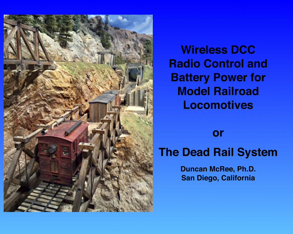
Wireless DCCRadio Control and Battery Power for
Model Railroad Locomotives
orThe Dead Rail System
Duncan McRee, Ph.D.San Diego, California
Copyright 2012 by Duncan McReeDead Rail Society Logo Copyright Robert Treat
Wireless DCC - Duncan McRee
2
On The Cover: A Dead Rail Box-cab locomotive by Justin Rasas pulling a train over a bridge on Dave
Balser’s now defunct Onion Valley Railroad.
A Dead Rail Society Publication
Introduction! 5
Chapter 1 - What is Wireless DCC?! 6
An Example Installation - On30 Bachmann Forney! 8
Programming the Decoder! 10
Chapter 2 - Batteries! 11
Nickel Cadmium and Nickel Metal Hydride! 11
Lithium! 12
Connecting cells together! 13
Wiring Cells! 13
Chapter 3 - The Radio ! 14
Chapter 4 - Installation! 18
Some example installations! 19
Chapter 5 - Charging from the track! 25
A simper system with NiMH Batteries! 28
The Future ! 31
Appendix - Technical Details ! 33
The Radios! 33
Schematics! 34
DIY wDCC! 36
Testing! 38
Troubleshooting! 38
Sources! 40
DRS1 System Sales and Installations! 40
Mike’s Backshop! 40
Lin's Junction! 40
Litchfield Station! 40
Parts Suppliers! 40
DRS1 Parts List! 41
Wireless DCC - Duncan McRee
4
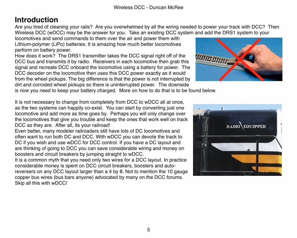
IntroductionAre you tired of cleaning your rails? Are you overwhelmed by all the wiring needed to power your track with DCC? Then Wireless DCC (wDCC) may be the answer for you. Take an existing DCC system and add the DRS1 system to your locomotives and send commands to them over the air and power them with Lithium-polymer (LiPo) batteries. It is amazing how much better locomotives perform on battery power.How does it work? The DRS1 transmitter takes the DCC signal right off of the DCC bus and transmits it by radio. Receivers in each locomotive then grab this signal and recreate DCC onboard the locomotive using a battery for power. The DCC decoder on the locomotive then uses this DCC power exactly as it would from the wheel pickups. The big difference is that the power is not interrupted by dirt and corroded wheel pickups so there is uninterrupted power. The downside is now you need to keep your battery charged. More on how to do that is to be found below.
It is not necessary to change from completely from DCC to wDCC all at once, as the two systems can happily co-exist. You can start by converting just one locomotive and add more as time goes by. Perhaps you will only change over the locomotives that give you trouble and keep the ones that work well on track DCC as they are. After all, its your railroad!Even better, many modeler railroaders still have lots of DC locomotives and often want to run both DC and DCC. With wDCC you can devote the track to DC if you wish and use wDCC for DCC control. If you have a DC layout and are thinking of going to DCC you can save considerable wiring and money on boosters and circuit breakers by jumping straight to wDCC.It is a common myth that you need only two wires for a DCC layout. In practice considerable money is spent on DCC circuit breakers, boosters and auto-reversers on any DCC layout larger than a 4 by 8. Not to mention the 10 gauge copper bus wires (bus bars anyone) advocated by many on the DCC forums. Skip all this with wDCC!
Wireless DCC - Duncan McRee
5
Chapter 1 - What is Wireless DCC?
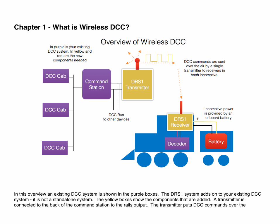
In this overview an existing DCC system is shown in the purple boxes. The DRS1 system adds on to your existing DCC system - it is not a standalone system. The yellow boxes show the components that are added. A transmitter is connected to the back of the command station to the rails output. The transmitter puts DCC commands over the
airwaves. It makes no attempt to filter the commands in any way; all the commands that would be put on to the track go over the air. You can keep your track connection at the same time. The wDCC system is completely compatible with normal DCC over the track. If you already have a wired layout, you can keep all of your existing infrastructure and add the wDCC to it. A single transmitted is used to transmit to as many locomotives as needed. Unlike a conventional DCC system where more power is needed for each locomotive on the track, each additional locomotive with a wDCC receiver provides on additional load as any power needed is provided by the battery on the locomotive.
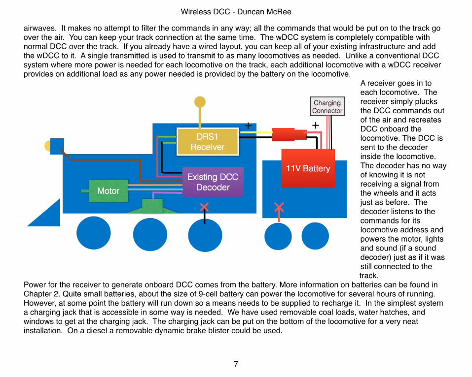
A receiver goes in to each locomotive. The receiver simply plucks the DCC commands out of the air and recreates DCC onboard the locomotive. The DCC is sent to the decoder inside the locomotive. The decoder has no way of knowing it is not receiving a signal from the wheels and it acts just as before. The decoder listens to the commands for its locomotive address and powers the motor, lights and sound (if a sound decoder) just as if it was still connected to the track.
Power for the receiver to generate onboard DCC comes from the battery. More information on batteries can be found in Chapter 2. Quite small batteries, about the size of 9-cell battery can power the locomotive for several hours of running. However, at some point the battery will run down so a means needs to be supplied to recharge it. In the simplest system a charging jack that is accessible in some way is needed. We have used removable coal loads, water hatches, and windows to get at the charging jack. The charging jack can be put on the bottom of the locomotive for a very neat installation. On a diesel a removable dynamic brake blister could be used.
Wireless DCC - Duncan McRee
7
An Example Installation - On30 Bachmann Forney
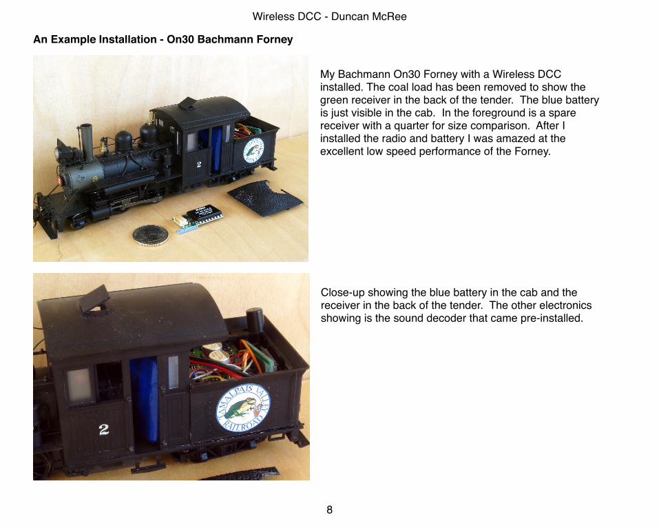
My Bachmann On30 Forney with a Wireless DCC installed. The coal load has been removed to show the green receiver in the back of the tender. The blue battery is just visible in the cab. In the foreground is a spare receiver with a quarter for size comparison. After I installed the radio and battery I was amazed at the excellent low speed performance of the Forney.
Close-up showing the blue battery in the cab and the receiver in the back of the tender. The other electronics showing is the sound decoder that came pre-installed.
Wireless DCC - Duncan McRee
8
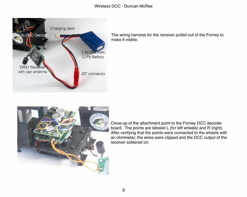
The wiring harness for the receiver pulled out of the Forney to make it visible.
Close-up of the attachment point to the Forney DCC decoder board. The points are labeled L (for left wheels) and R (right). After verifying that the points were connected to the wheels with an ohmmeter, the wires were clipped and the DCC output of the receiver soldered on.
Wireless DCC - Duncan McRee
9
Programming the DecoderThere are basically two ways to program a DCC decoder installed in a locomotive.Programming on the MainYou can use Programming on the Main for most CV values just as you would for a locomotive on the mainline of any DCC layout. However some decoders will not let you change the locomotive address this way. Service Mode (program track)For setting the address you can hook the transmitter to the programming track. Make sure only the locomotive you want to program is turned on as any locomotive that is turned on will be programmed! You cannot read the CV values back but you should see the locomotive move slightly when it accepts the programming instruction.
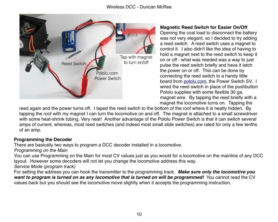
Magnetic Reed Switch for Easier On/OffOpening the coal load to disconnect the battery was not very elegant, so I decided to try adding a reed switch. A reed switch uses a magnet to control it. I also didn't like the idea of having to hold a magnet next to the reed switch to keep it on or off - what was needed was a way to just pulse the reed switch briefly and have it latch the power on or off. This can be done by connecting the reed switch to a handy little board from pololu.com, the Power Switch SV. I wired the reed switch in place of the pushbutton Pololu supplies with some flexible 30 ga. magnet wire. By tapping the reed briefly with a magnet the locomotive turns on. Tapping the
reed again and the power turns off. I taped the reed switch to the bottom of the roof where it is neatly hidden. By tapping the roof with my magnet I can turn the locomotive on and off. The magnet is attached to a small screwdriver with some heat-shrink tubing. Very neat! Another advantage of the Pololu Power Switch is that it can switch several amps of current, whereas, most reed switches (and indeed most small slide switches) are rated for only a few tenths of an amp.
Wireless DCC - Duncan McRee
10
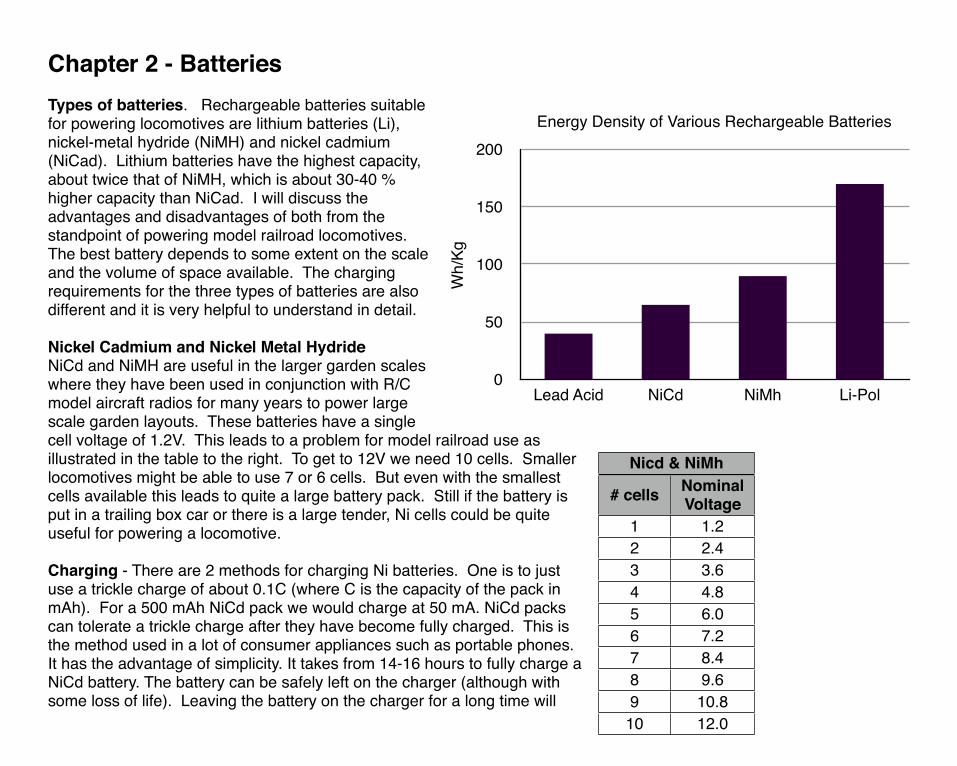
Chapter 2 - BatteriesTypes of batteries. Rechargeable batteries suitable for powering locomotives are lithium batteries (Li), nickel-metal hydride (NiMH) and nickel cadmium (NiCad). Lithium batteries have the highest capacity, about twice that of NiMH, which is about 30-40 % higher capacity than NiCad. I will discuss the advantages and disadvantages of both from the standpoint of powering model railroad locomotives. The best battery depends to some extent on the scale and the volume of space available. The charging requirements for the three types of batteries are also different and it is very helpful to understand in detail.
Nickel Cadmium and Nickel Metal HydrideNiCd and NiMH are useful in the larger garden scales where they have been used in conjunction with R/C model aircraft radios for many years to power large scale garden layouts. These batteries have a single cell voltage of 1.2V. This leads to a problem for model railroad use as illustrated in the table to the right. To get to 12V we need 10 cells. Smaller locomotives might be able to use 7 or 6 cells. But even with the smallest cells available this leads to quite a large battery pack. Still if the battery is put in a trailing box car or there is a large tender, Ni cells could be quite useful for powering a locomotive.
Charging - There are 2 methods for charging Ni batteries. One is to just use a trickle charge of about 0.1C (where C is the capacity of the pack in mAh). For a 500 mAh NiCd pack we would charge at 50 mA. NiCd packs can tolerate a trickle charge after they have become fully charged. This is the method used in a lot of consumer appliances such as portable phones. It has the advantage of simplicity. It takes from 14-16 hours to fully charge a NiCd battery. The battery can be safely left on the charger (although with some loss of life). Leaving the battery on the charger for a long time will
0
50
100
150
200
Lead Acid NiCd NiMh Li-Pol
Energy Density of Various Rechargeable Batteries
Wh/
KgNicd & NiMhNicd & NiMh
# cells Nominal Voltage
1 1.22 2.43 3.64 4.85 6.06 7.27 8.48 9.69 10.8
10 12.0
eventually damage the battery. This is at first an attractive method for charging batteries in a model locomotive. However, the issue becomes the long charging time. If the battery is too small and it runs down it takes far too long for the battery to recharge. This needs to be carefully worked out for each locomotive and its current use. Also constantly trickle charging the battery will lead to a short battery life. NiMh is also resistant to trickle charging.
The second method is to charge the batteries at higher rate, say 0.3C - 1.0C or higher and monitor the battery voltage. When it gets to a certain value the charger is disconnected. A dedicated charger is used that can detect the charge state of the battery and shut off when the battery is full. Slightly different methods are used for NiMH and for NiCd batteries so it is important to use the correct charger for the battery type.
NiCd batteries exhibit an called memory where they will not fully charge if they are partially charged several times. To counteract this a NiCd battery can periodically fully discharged and then given a full charge. This is referred to as cycling the battery and will help counteract the memory effect.
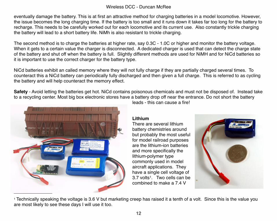
Safety - Avoid letting the batteries get hot. NiCd contains poisonous chemicals and must not be disposed of. Instead take to a recycling center. Most big box electronic stores have a battery drop off near the entrance. Do not short the battery
leads - this can cause a fire!
LithiumThere are several lithium battery chemistries around but probably the most useful for model railroad purposes are the lithium-ion batteries and more specifically the lithium-polymer type commonly used in model aircraft applications. They have a single cell voltage of 3.7 volts1. Two cells can be combined to make a 7.4 V
Wireless DCC - Duncan McRee
12
1 Technically speaking the voltage is 3.6 V but marketing creep has raised it a tenth of a volt. Since this is the value you are most likely to see these days I will use it too.
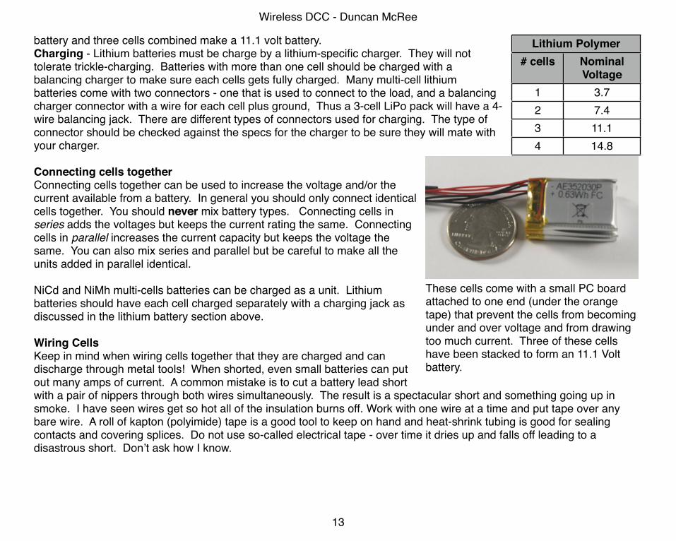
battery and three cells combined make a 11.1 volt battery.Charging - Lithium batteries must be charge by a lithium-specific charger. They will not tolerate trickle-charging. Batteries with more than one cell should be charged with a balancing charger to make sure each cells gets fully charged. Many multi-cell lithium batteries come with two connectors - one that is used to connect to the load, and a balancing charger connector with a wire for each cell plus ground, Thus a 3-cell LiPo pack will have a 4-wire balancing jack. There are different types of connectors used for charging. The type of connector should be checked against the specs for the charger to be sure they will mate with your charger.
Connecting cells togetherConnecting cells together can be used to increase the voltage and/or the current available from a battery. In general you should only connect identical cells together. You should never mix battery types. Connecting cells in series adds the voltages but keeps the current rating the same. Connecting cells in parallel increases the current capacity but keeps the voltage the same. You can also mix series and parallel but be careful to make all the units added in parallel identical.
NiCd and NiMh multi-cells batteries can be charged as a unit. Lithium batteries should have each cell charged separately with a charging jack as discussed in the lithium battery section above.
Wiring CellsKeep in mind when wiring cells together that they are charged and can discharge through metal tools! When shorted, even small batteries can put out many amps of current. A common mistake is to cut a battery lead short with a pair of nippers through both wires simultaneously. The result is a spectacular short and something going up in smoke. I have seen wires get so hot all of the insulation burns off. Work with one wire at a time and put tape over any bare wire. A roll of kapton (polyimide) tape is a good tool to keep on hand and heat-shrink tubing is good for sealing contacts and covering splices. Do not use so-called electrical tape - over time it dries up and falls off leading to a disastrous short. Don’t ask how I know.
Wireless DCC - Duncan McRee
13
Lithium PolymerLithium Polymer# cells Nominal
Voltage1 3.72 7.43 11.14 14.8
These cells come with a small PC board attached to one end (under the orange tape) that prevent the cells from becoming under and over voltage and from drawing too much current. Three of these cells have been stacked to form an 11.1 Volt battery.
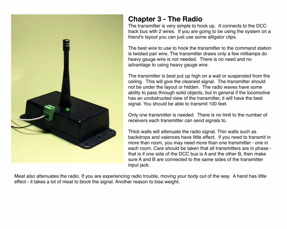
Chapter 3 - The RadioThe transmitter is very simple to hook up. It connects to the DCC track bus with 2 wires. If you are going to be using the system on a friend's layout you can just use some alligator clips.
The best wire to use to hook the transmitter to the command station is twisted pair wire. The transmitter draws only a few milliamps do heavy gauge wire is not needed. There is no need and no advantage to using heavy gauge wire.
The transmitter is best put up high on a wall or suspended from the ceiling. This will give the cleanest signal. The transmitter should not be under the layout or hidden. The radio waves have some ability to pass through solid objects, but in general if the locomotive has an unobstructed view of the transmitter, it will have the best signal. You should be able to transmit 100 feet.
Only one transmitter is needed. There is no limit to the number of receivers each transmitter can send signals to.
Thick walls will attenuate the radio signal. Thin walls such as backdrops and valences have little effect. If you need to transmit in more than room, you may need more than one transmitter - one in each room. Care should be taken that all transmitters are in phase - that is if one side of the DCC bus is A and the other B, then make sure A and B are connected to the same sides of the transmitter input jack.
Meat also attenuates the radio. If you are experiencing radio trouble, moving your body out of the way. A hand has little effect - it takes a lot of meat to block the signal. Another reason to lose weight.
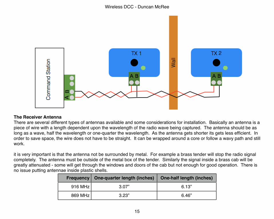
The Receiver AntennaThere are several different types of antennas available and some considerations for installation. Basically an antenna is a piece of wire with a length dependent upon the wavelength of the radio wave being captured. The antenna should be as long as a wave, half the wavelength or one-quarter the wavelength. As the antenna gets shorter its gets less efficient. In order to save space, the wire does not have to be straight. It can be wrapped around a core or follow a wavy path and still work.
it is very important is that the antenna not be surrounded by metal. For example a brass tender will stop the radio signal completely. The antenna must be outside of the metal box of the tender. Similarly the signal inside a brass cab will be greatly attenuated - some will get through the windows and doors of the cab but not enough for good operation. There is no issue putting antennae inside plastic shells.
Frequency One-quarter length (inches) One-half length (inches)
916 MHz 3.07” 6.13”
869 MHz 3.23” 6.46”
Wireless DCC - Duncan McRee
15
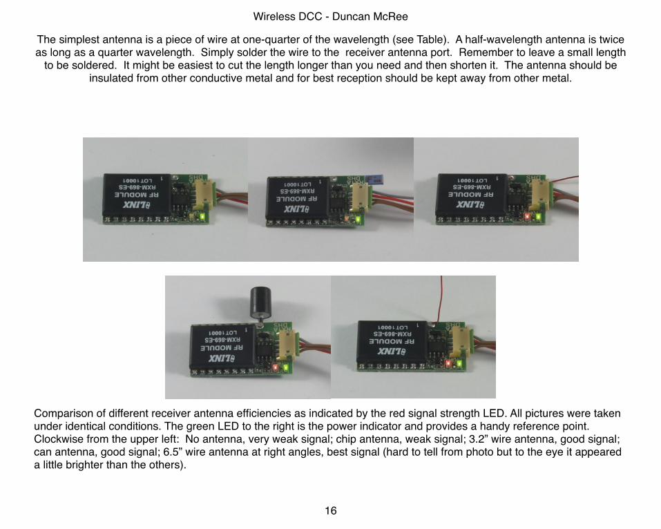
The simplest antenna is a piece of wire at one-quarter of the wavelength (see Table). A half-wavelength antenna is twice as long as a quarter wavelength. Simply solder the wire to the receiver antenna port. Remember to leave a small length
to be soldered. It might be easiest to cut the length longer than you need and then shorten it. The antenna should be insulated from other conductive metal and for best reception should be kept away from other metal.
Comparison of different receiver antenna efficiencies as indicated by the red signal strength LED. All pictures were taken under identical conditions. The green LED to the right is the power indicator and provides a handy reference point. Clockwise from the upper left: No antenna, very weak signal; chip antenna, weak signal; 3.2” wire antenna, good signal; can antenna, good signal; 6.5” wire antenna at right angles, best signal (hard to tell from photo but to the eye it appeared a little brighter than the others).
Wireless DCC - Duncan McRee
16
Wireless DCC - Duncan McRee
17
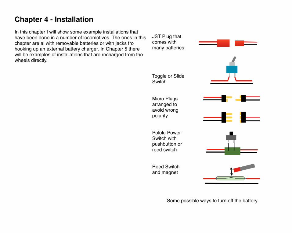
Chapter 4 - InstallationIn this chapter I will show some example installations that have been done in a number of locomotives. The ones in this chapter are al with removable batteries or with jacks fro hooking up an external battery charger. In Chapter 5 there will be examples of installations that are recharged from the wheels directly.
JST Plug that comes with many batteries
Toggle or Slide Switch
Micro Plugs arranged to avoid wrong polarity
Pololu Power Switch with pushbutton or reed switch
Reed Switch and magnet
Some possible ways to turn off the battery
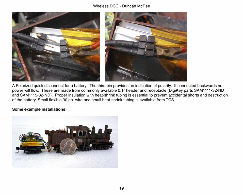
A Polarized quick disconnect for a battery. The third pin provides an indication of polarity. If connected backwards no power will flow. These are made from commonly available 0.1” header and receptacle (DigiKey parts SAM1111-32-ND and SAM1115-32-ND). Proper insulation with heat-shrink tubing is essential to prevent accidental shorts and destruction of the battery. Small flexible 30 ga. wire and small heat-shrink tubing is available from TCS.
Some example installations
Wireless DCC - Duncan McRee
19
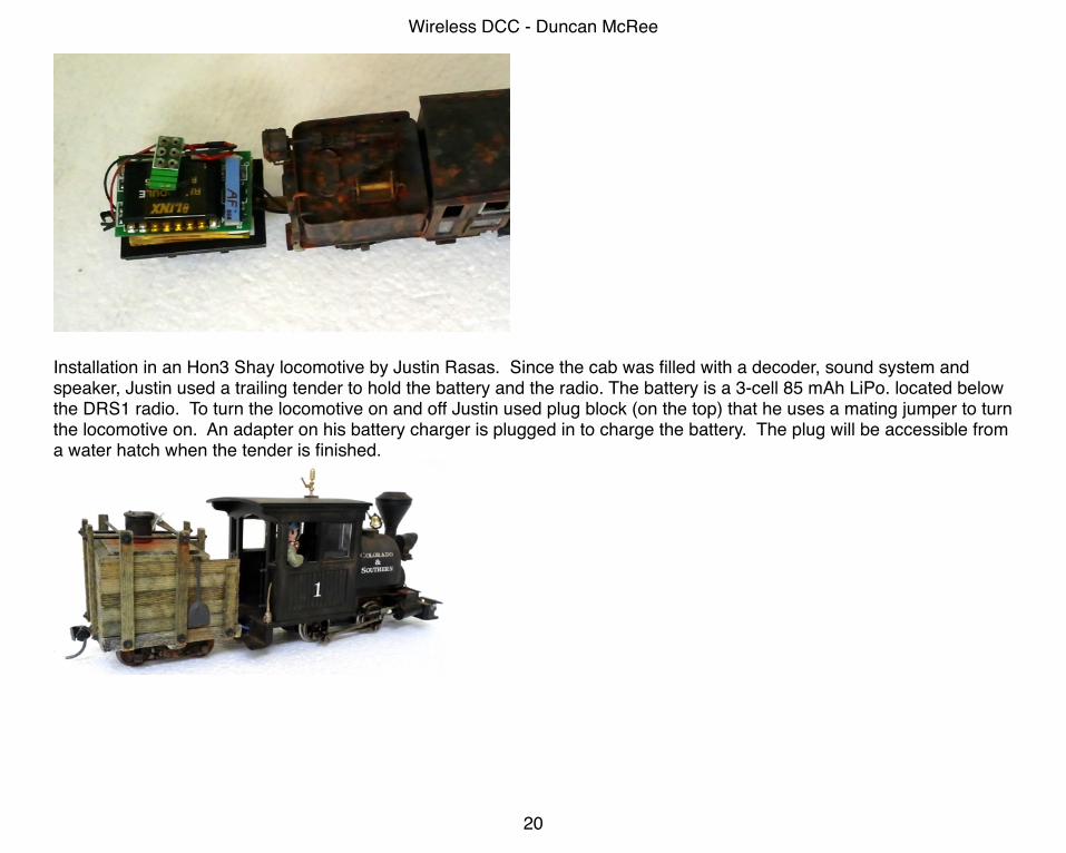
Installation in an Hon3 Shay locomotive by Justin Rasas. Since the cab was filled with a decoder, sound system and speaker, Justin used a trailing tender to hold the battery and the radio. The battery is a 3-cell 85 mAh LiPo. located below the DRS1 radio. To turn the locomotive on and off Justin used plug block (on the top) that he uses a mating jumper to turn the locomotive on. An adapter on his battery charger is plugged in to charge the battery. The plug will be accessible from a water hatch when the tender is finished.
Wireless DCC - Duncan McRee
20
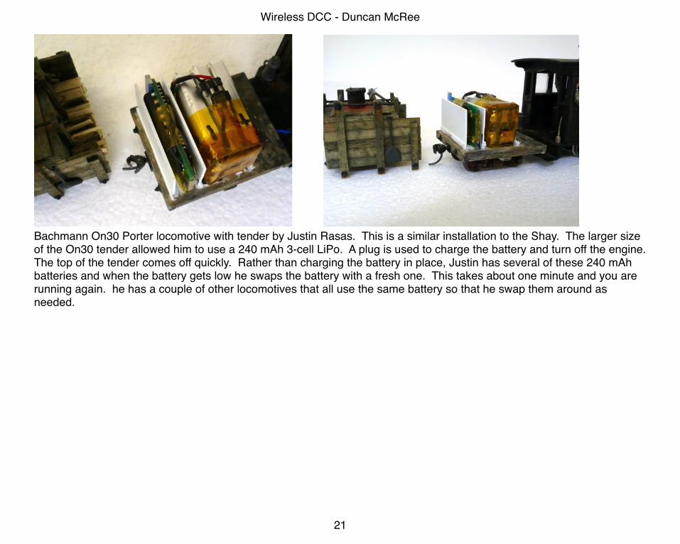
Bachmann On30 Porter locomotive with tender by Justin Rasas. This is a similar installation to the Shay. The larger size of the On30 tender allowed him to use a 240 mAh 3-cell LiPo. A plug is used to charge the battery and turn off the engine. The top of the tender comes off quickly. Rather than charging the battery in place, Justin has several of these 240 mAh batteries and when the battery gets low he swaps the battery with a fresh one. This takes about one minute and you are running again. he has a couple of other locomotives that all use the same battery so that he swap them around as needed.
Wireless DCC - Duncan McRee
21
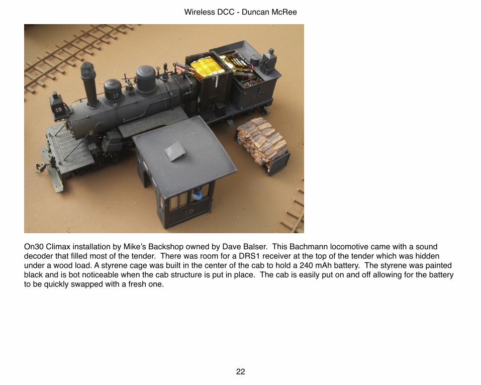
On30 Climax installation by Mike’s Backshop owned by Dave Balser. This Bachmann locomotive came with a sound decoder that filled most of the tender. There was room for a DRS1 receiver at the top of the tender which was hidden under a wood load. A styrene cage was built in the center of the cab to hold a 240 mAh battery. The styrene was painted black and is bot noticeable when the cab structure is put in place. The cab is easily put on and off allowing for the battery to be quickly swapped with a fresh one.
Wireless DCC - Duncan McRee
22
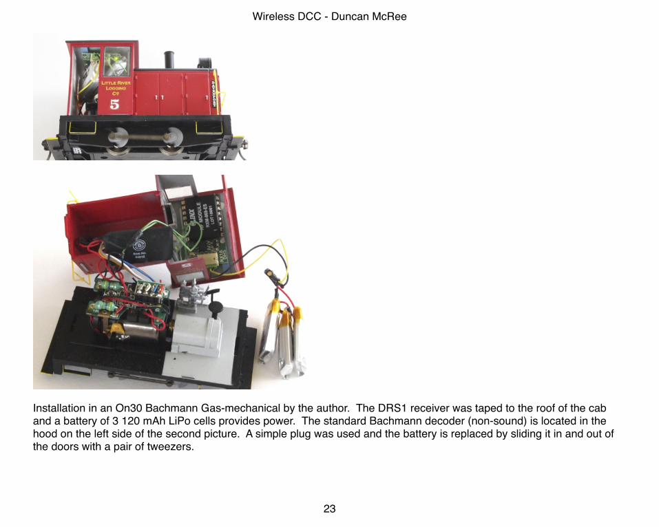
Installation in an On30 Bachmann Gas-mechanical by the author. The DRS1 receiver was taped to the roof of the cab and a battery of 3 120 mAh LiPo cells provides power. The standard Bachmann decoder (non-sound) is located in the hood on the left side of the second picture. A simple plug was used and the battery is replaced by sliding it in and out of the doors with a pair of tweezers.
Wireless DCC - Duncan McRee
23
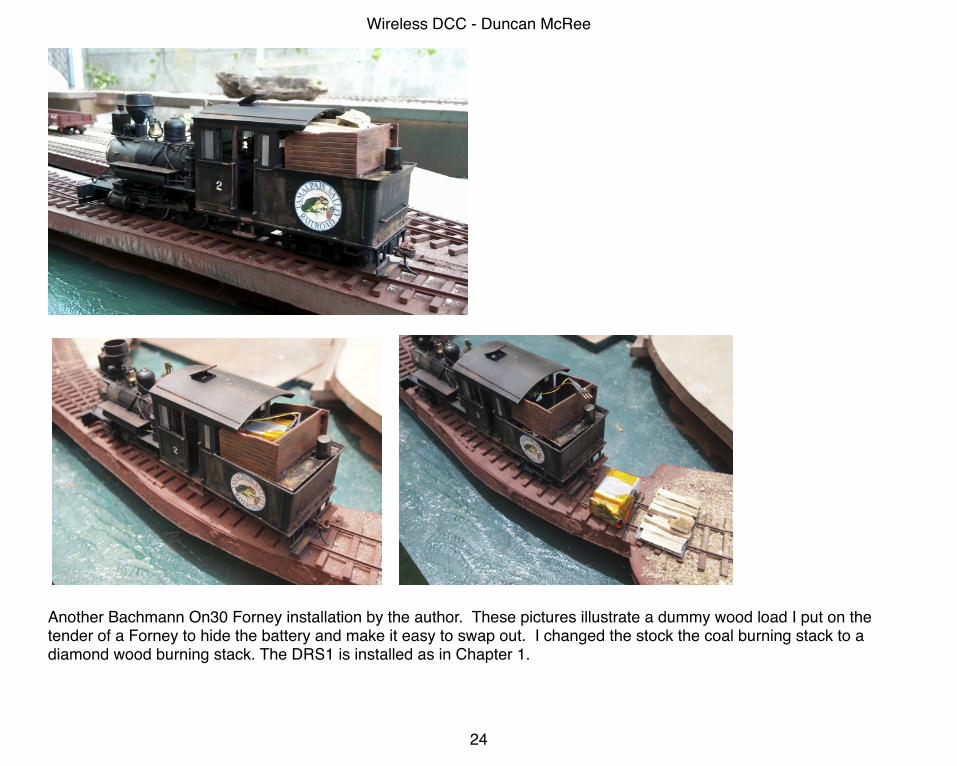
Another Bachmann On30 Forney installation by the author. These pictures illustrate a dummy wood load I put on the tender of a Forney to hide the battery and make it easy to swap out. I changed the stock the coal burning stack to a diamond wood burning stack. The DRS1 is installed as in Chapter 1.
Wireless DCC - Duncan McRee
24
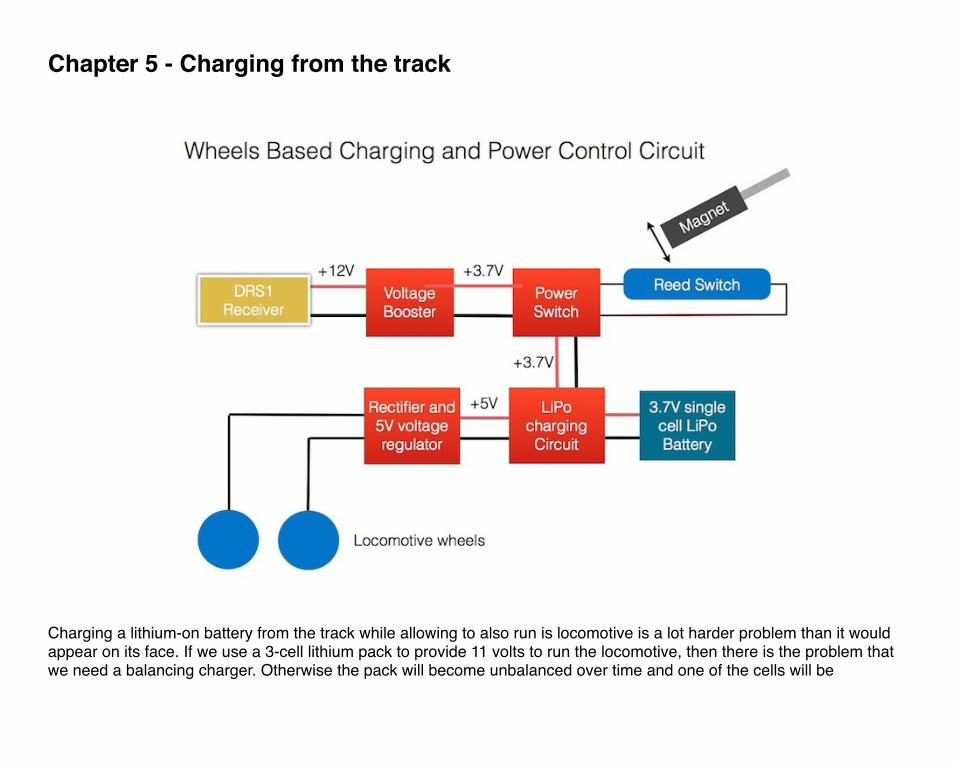
Chapter 5 - Charging from the track
Charging a lithium-on battery from the track while allowing to also run is locomotive is a lot harder problem than it would appear on its face. If we use a 3-cell lithium pack to provide 11 volts to run the locomotive, then there is the problem that we need a balancing charger. Otherwise the pack will become unbalanced over time and one of the cells will be
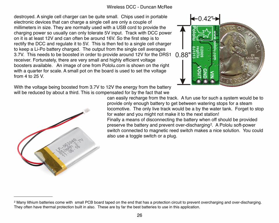
destroyed. A single cell charger can be quite small. Chips used in portable electronic devices that can charge a single cell are only a couple of millimeters in size. They are normally used with a USB cord to provide the charging power so usually can only tolerate 5V input. Track with DCC power on it is at least 12V and can often be around 16V. So the first step is to rectify the DCC and regulate it to 5V. This is then fed to a single cell charger to keep a Li-Po battery charged. The output from the single cell averages 3.7V. This needs to be boosted in order to provide around 12V for the DRS1 receiver. Fortunately, there are very small and highly efficient voltage boosters available. An image of one from Pololu.com is shown on the right with a quarter for scale. A small pot on the board is used to set the voltage from 4 to 25 V.
With the voltage being boosted from 3.7V to 12V the energy from the battery will be reduced by about a third. This is compensated for by the fact that we
can easily recharge from the track. A fun use for such a system would be to provide only enough battery to get between watering stops for a steam locomotive. The only live track would be a by the water tank. Forget to stop for water and you might not make it to the next station!Finally a means of disconnecting the battery when off should be provided preserve the battery and prevent over-discharging2. A Pololu soft-power switch connected to magnetic reed switch makes a nice solution. You could also use a toggle switch or a plug.
Wireless DCC - Duncan McRee
26
2 Many lithium batteries come with small PCB board taped on the end that has a protection circuit to prevent overcharging and over-discharging. They often have thermal protection built in also. These are by far the best batteries to use in this application.
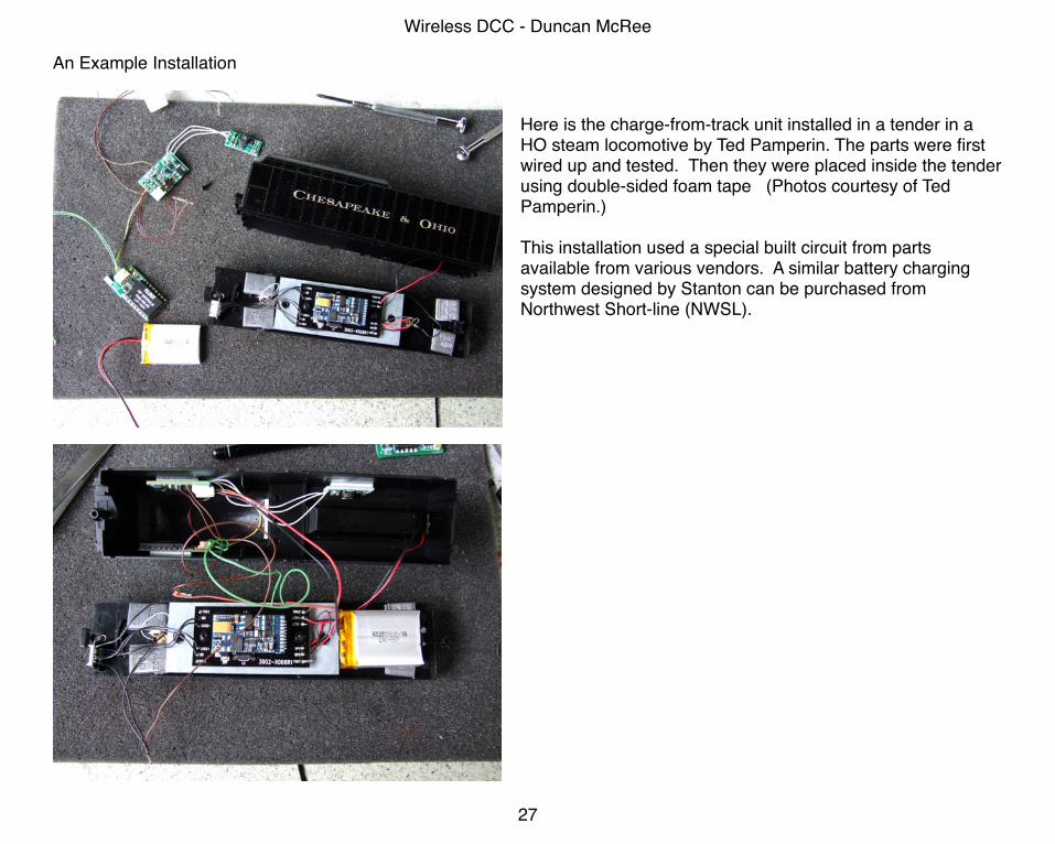
An Example Installation
Here is the charge-from-track unit installed in a tender in a HO steam locomotive by Ted Pamperin. The parts were first wired up and tested. Then they were placed inside the tender using double-sided foam tape (Photos courtesy of Ted Pamperin.)
This installation used a special built circuit from parts available from various vendors. A similar battery charging system designed by Stanton can be purchased from Northwest Short-line (NWSL).
Wireless DCC - Duncan McRee
27
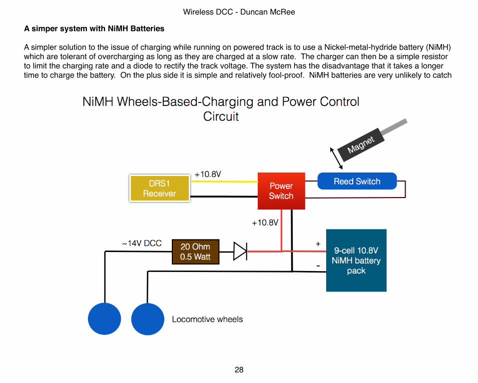
A simper system with NiMH Batteries
A simpler solution to the issue of charging while running on powered track is to use a Nickel-metal-hydride battery (NiMH) which are tolerant of overcharging as long as they are charged at a slow rate. The charger can then be a simple resistor to limit the charging rate and a diode to rectify the track voltage. The system has the disadvantage that it takes a longer time to charge the battery. On the plus side it is simple and relatively fool-proof. NiMH batteries are very unlikely to catch
Wireless DCC - Duncan McRee
28
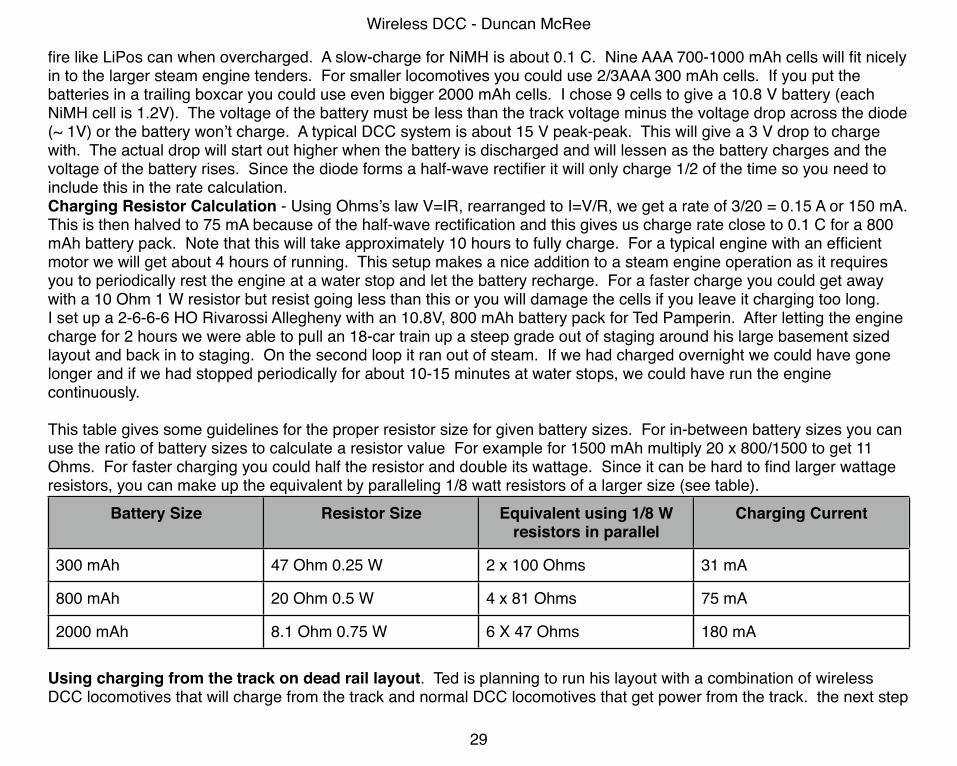
fire like LiPos can when overcharged. A slow-charge for NiMH is about 0.1 C. Nine AAA 700-1000 mAh cells will fit nicely in to the larger steam engine tenders. For smaller locomotives you could use 2/3AAA 300 mAh cells. If you put the batteries in a trailing boxcar you could use even bigger 2000 mAh cells. I chose 9 cells to give a 10.8 V battery (each NiMH cell is 1.2V). The voltage of the battery must be less than the track voltage minus the voltage drop across the diode (~ 1V) or the battery won’t charge. A typical DCC system is about 15 V peak-peak. This will give a 3 V drop to charge with. The actual drop will start out higher when the battery is discharged and will lessen as the battery charges and the voltage of the battery rises. Since the diode forms a half-wave rectifier it will only charge 1/2 of the time so you need to include this in the rate calculation.Charging Resistor Calculation - Using Ohms’s law V=IR, rearranged to I=V/R, we get a rate of 3/20 = 0.15 A or 150 mA. This is then halved to 75 mA because of the half-wave rectification and this gives us charge rate close to 0.1 C for a 800 mAh battery pack. Note that this will take approximately 10 hours to fully charge. For a typical engine with an efficient motor we will get about 4 hours of running. This setup makes a nice addition to a steam engine operation as it requires you to periodically rest the engine at a water stop and let the battery recharge. For a faster charge you could get away with a 10 Ohm 1 W resistor but resist going less than this or you will damage the cells if you leave it charging too long.I set up a 2-6-6-6 HO Rivarossi Allegheny with an 10.8V, 800 mAh battery pack for Ted Pamperin. After letting the engine charge for 2 hours we were able to pull an 18-car train up a steep grade out of staging around his large basement sized layout and back in to staging. On the second loop it ran out of steam. If we had charged overnight we could have gone longer and if we had stopped periodically for about 10-15 minutes at water stops, we could have run the engine continuously.
This table gives some guidelines for the proper resistor size for given battery sizes. For in-between battery sizes you can use the ratio of battery sizes to calculate a resistor value For example for 1500 mAh multiply 20 x 800/1500 to get 11 Ohms. For faster charging you could half the resistor and double its wattage. Since it can be hard to find larger wattage resistors, you can make up the equivalent by paralleling 1/8 watt resistors of a larger size (see table).
Battery Size Resistor Size Equivalent using 1/8 W resistors in parallel
Charging Current
300 mAh 47 Ohm 0.25 W 2 x 100 Ohms 31 mA
800 mAh 20 Ohm 0.5 W 4 x 81 Ohms 75 mA
2000 mAh 8.1 Ohm 0.75 W 6 X 47 Ohms 180 mA
Using charging from the track on dead rail layout. Ted is planning to run his layout with a combination of wireless DCC locomotives that will charge from the track and normal DCC locomotives that get power from the track. the next step
Wireless DCC - Duncan McRee
29
is to get rid of the DCC power in the track. A layout built like this with dead rails, would save a lot of money effort in not have to wire the layout with power districts, DCC breakers, auto-reversers and frog juicers. Instead you could have strategically placed stretches of track with power for charging. These would be located in the engine terminal and by water/fuel stops. Running a locomotive on such a layout the operators would have to pay attention to keeping the locomotive properly charged - the analog of fuel and water in the prototype. More fun!
Wireless DCC - Duncan McRee
30
The FutureWhere will wireless DCC go in the future? Although no one knows the future for certain, here are some educated guesses.
Better radios. The radio I used in the DRS1 was used mainly for its small size and its relative inexpensiveness. The trend in RC control has been to go to 2.4 GHz radios and to go towards radios that can channel hop to avoid interference with other devices on 2.4 GHz, such as wireless routers and portable phones. An interesting development has been a standard called Zigbee. It has the interesting ability to make a web-based network of radios. This way low-power radios can be used and a message sent a longer distance by hopping the message from radio to radio until it reaches the intended target (locomotive). Thus a large layout might have some radios at strategic locations hidden under the scenery to act as relays. Each net is identified with a unique pin code. At a train show where several modular groups could be operating simultaneously, each group would have its own unique pin code that would prevent the groups interfering with each other. If a friend showed up at your layout with a throttle with a Zigbee in it, you would tell him the PIN and he could operate your locomotives.Another direction would be to use small WiFi radios of the type used in smart phones. A wireless router could be used to create a network of throttles and locomotives. The throttles could be purpose made units or they could be smartphones or tablets. A computer running JMRI and the its builtin WiFi server is used to supply routes, turnouts and a roster of locomotives. This is similar to the setup explained earlier in the book except a DCC command station would not be needed at all. Similarly, several modular groups can co-exist with this setup since a number of WiFi networks can exist in the same area - you would join the group for the modular layout you want to operate and enter its password.
Wireless power. It is possible to use a small battery and have it charged through inductance from a wireless charger consisting of a loop. In the locomotive a smaller loop would pick up the power and charge the battery. There has been lots of talk of using a system like this for charging cell phones and the like. A number of these systems exist today but, as of this writing, none have taken off - probably because the wall plug in your home is cheap and power jacks are readily available in cars, airports and hotels. It would be fun to have a battery charging station in your engine terminal with a charging loop under the ready track for charging locomotives. Additional charging loops could be made available at water stops.
Smart Locomotives. Since the radios described above are bidirectional you can get messages back from the locomotives. This would allow for a battery level indicator (fuel/water gauge), real-time speed feedback, diagnostic information and even a low-resolution video shot from the cab. It would be a lot easier to program the locomotive with direct feedback. In fact less programming would be needed since a lot of the information could be stored in the throttle an uploaded on the fly. For example, a slider for momentum could pop up on the throttle and you could use this to vary the
momentum of the locomotive in real-time. Different operators could have their own momentum settings for the same engine and their setting could be uploaded when they grabbed the engine.
Location Services. Just like your smartphone can estimate its position from the signal strength of nearby cell towers, a locomotive could estimate its location from the strength of marker radios on the layout. They could thus know when they were entering a town or yard and send this information back to the throttle. In turn, the throttle could show relevant information for that location such as the track-plan, location of industries and so forth. Virtual train signals could display on the throttle giving the proper signals from a CTC system. This would help enormously with setting up a signal system. One difficulty on current signaled layouts is seeing the tiny signal from non-optimal viewing points. In a virtual signal system the signals would be easily seen on the throttle screen. Finally a virtual signaling system would be vastly less expensive. the location could also be used to generate the proper sound by interfacing the location information to a SurroundTrax sound system.The marker radios could be located in the four corners of a room. To calibrate the system you could imagine driving a locomotive around the layout and telling the system the current location of the locomotive. the system would then memorize the relative signal strengths and associate these with a particular town on the layout.
Wireless DCC - Duncan McRee
32
Appendix - Technical DetailsThe Radios
The wireless radios I use for the DRS1 are available from LINX Technologies. Electronic suppliers such as Mouser and Digi-Key carry them. These radios act as radio substitute for a piece of wire - they mirror whatever signal comes in on the data input of the transmitter and mirror on the receiver data line - subject to available bandwidth. All that is required is to add an antenna, to provide power and data. The bandwidth of a DCC signal is set by the 58 microsecond half-bit time for a “one”3. This gives us a minimum bandwidth requirement of 17.2 KHz. Looking at LINX data sheets this limits us to radios of 869 MHz and above. The smallest receivers are on the LINX RXM-869-ES (869 MHz, so-called Euro frequency) and the RXM-916-ES (916 MHz, Instrument-Medical band). The corresponding transmitters are the TXM-869-ES and the TXM-916-ES. In the US 869 Mhz is allocated to cell phones. However both these transmitters only use 8.5 mA when transmitting and if you did have a cell phone on the exact frequency, it would have to be right next to the transmitter to be interfered with. With 916 Mhz the bigger issue is that the frequency is popular with other radio devices used by model railroads for throttles and such. In fact some throttles use the exact same LINX radios - although this has been decreasing as these LINX radios are half-duplex and most throttles are moving towards full duplex. You will have to check with the throttle manufacturer to see what frequency they are using to see if there is interference. It is also the band used by 900Mhz portable phones. Most portable phones are frequency hopping these days so they can skip to a clear channel and avoid interference.
As far as I can see in the US the FCC allows for experimental use of the ISM band without needing to get FCC inspections. If you intend to make a marketable product then testing is needed to certify the product. This appears to be because an antenna is added to the system by the end user. More information is available at the LINX web-site. A ham radio license is not needed. Although ham radio training could be of a big benefit.
3 Each 1 or 0 on DCC acts as 2-bits when translated to digital logic, a 0 followed by a 1. Clever circuitry could reduce this to a single bit but at the expense of enlarging the receiver and increasing cost.
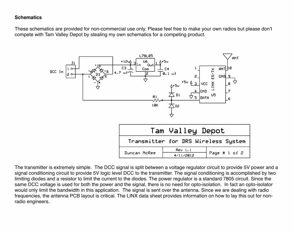
Schematics
These schematics are provided for non-commercial use only. Please feel free to make your own radios but please don’t compete with Tam Valley Depot by stealing my own schematics for a competing product.
The transmitter is extremely simple. The DCC signal is split between a voltage regulator circuit to provide 5V power and a signal conditioning circuit to provide 5V logic level DCC to the transmitter. The signal conditioning is accomplished by two limiting diodes and a resistor to limit the current to the diodes. The power regulator is a standard 7805 circuit. Since the same DCC voltage is used for both the power and the signal, there is no need for opto-isolation. In fact an opto-isolator would only limit the bandwidth in this application. The signal is sent over the antenna. Since we are dealing with radio frequencies, the antenna PCB layout is critical. The LINX data sheet provides information on how to lay this out for non-radio engineers.
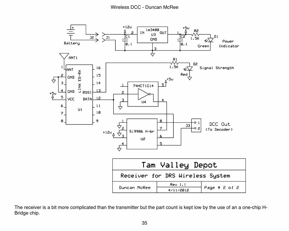
The receiver is a bit more complicated than the transmitter but the part count is kept low by the use of an a one-chip H-Bridge chip.
Wireless DCC - Duncan McRee
35
The battery is used to provide a 12V (or whatever voltage the battery is at) power supply and is regulated to 5V by the LM3480. The capacitors stabilize the regulator. The LED D1 and R2 provide a power indication to remind us to remove the battery when not in use.
The signal from the antenna is fed to the receiver and logic level DCC comes out of the data pin. The signal is sent through an inverter, U4, to provide a mirror image needed for the H-bridge. The (+) and inverted (-) signal is then fed to U2, a SI9986 single-chip H-bridge. Circuitry on the SI9986 takes care of issues with H-bridges such as overshoot and stabilization circuitry to provides a low part count of just one. The SI9986 can put out one amp continuous and close to two amps for a short burst. Some heat sinking is needed on the PC board to get the maximum performance out of the chip. This is done with vias to the copper ground plane on the PCB so that the whole PCB acts as thermal radiator. The output of U2 on pins 5 and 8 can be fed directly to a DCC decoder. Since the H-bridge is switching the power and not acting in a linear mode, it can pass a relatively high amperage without dissipating a lot of heat (i.e. it goes from a high-resistance off state to a low-resistance on-state in a very short time). This makes using a small PCB with no other heat-sink possible.
The signal strength is reported on the RSSI pin. Conveniently no signal is 1.7 V, the turn on voltage for most red LEDs and a strong signal approaches 3 volts which provides a bright indication on the LED. At low signal the 1.5K R1 resistor limits the current such that the LED will not light. The signal strength meter LED provides an invaluable resource for setting up the antenna and for troubleshooting radio interference.
Note that when the radio signal gets weak, the data line becomes noisy with very high frequency interference. The affect of this is that the H-bridge puts out power if the transmitter is turned off. If the decoder is set up to respond to DC then the locomotive will take off at a high rate of speed. The cure is to turn off the DC track option with the proper CV. You have no connections to the wheels any more so you can’t use the locomotive for DC!
DIY wDCC
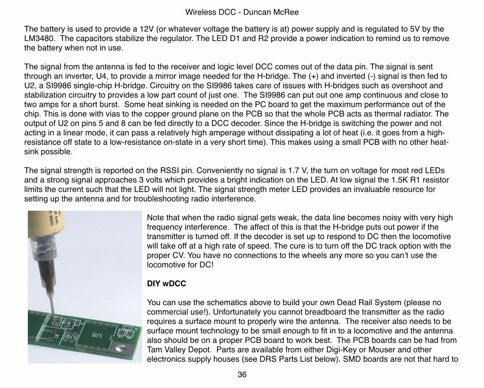
You can use the schematics above to build your own Dead Rail System (please no commercial use!). Unfortunately you cannot breadboard the transmitter as the radio requires a surface mount to properly wire the antenna. The receiver also needs to be surface mount technology to be small enough to fit in to a locomotive and the antenna also should be on a proper PCB board to work best. The PCB boards can be had from Tam Valley Depot. Parts are available from either Digi-Key or Mouser and other electronics supply houses (see DRS Parts List below). SMD boards are not that hard to
Wireless DCC - Duncan McRee
36
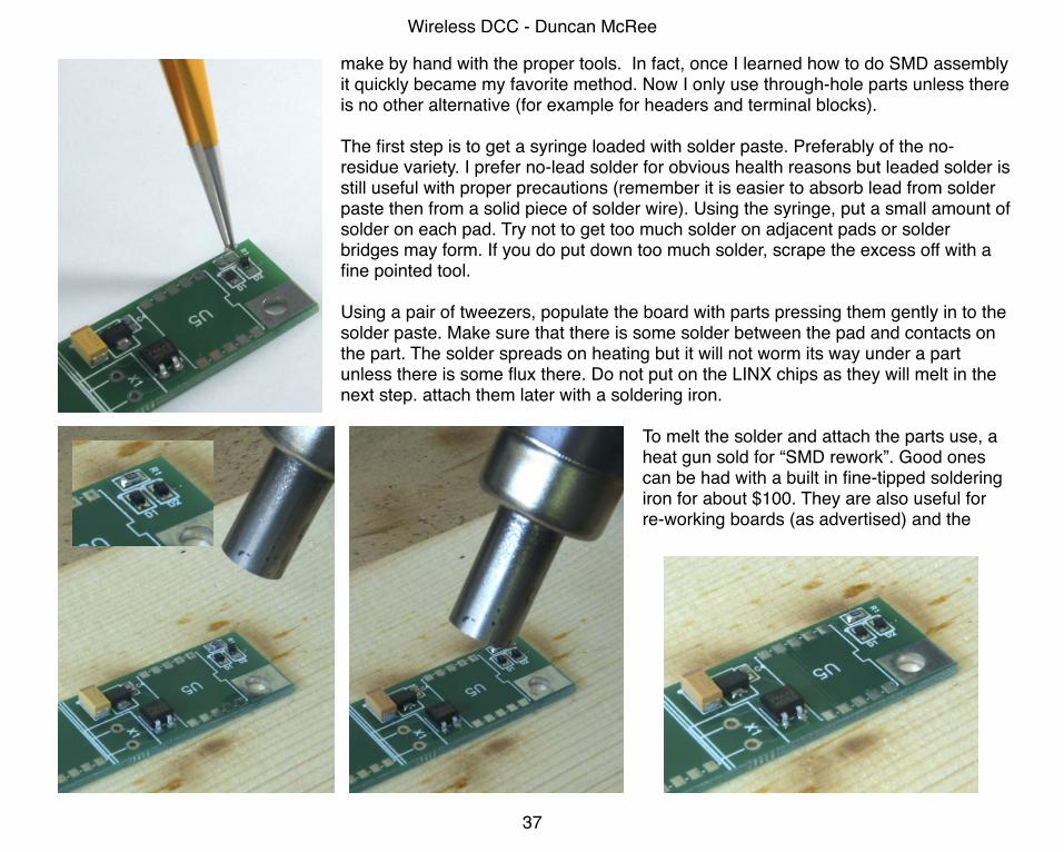
make by hand with the proper tools. In fact, once I learned how to do SMD assembly it quickly became my favorite method. Now I only use through-hole parts unless there is no other alternative (for example for headers and terminal blocks).
The first step is to get a syringe loaded with solder paste. Preferably of the no-residue variety. I prefer no-lead solder for obvious health reasons but leaded solder is still useful with proper precautions (remember it is easier to absorb lead from solder paste then from a solid piece of solder wire). Using the syringe, put a small amount of solder on each pad. Try not to get too much solder on adjacent pads or solder bridges may form. If you do put down too much solder, scrape the excess off with a fine pointed tool.
Using a pair of tweezers, populate the board with parts pressing them gently in to the solder paste. Make sure that there is some solder between the pad and contacts on the part. The solder spreads on heating but it will not worm its way under a part unless there is some flux there. Do not put on the LINX chips as they will melt in the next step. attach them later with a soldering iron.
To melt the solder and attach the parts use, a heat gun sold for “SMD rework”. Good ones can be had with a built in fine-tipped soldering iron for about $100. They are also useful for re-working boards (as advertised) and the
Wireless DCC - Duncan McRee
37
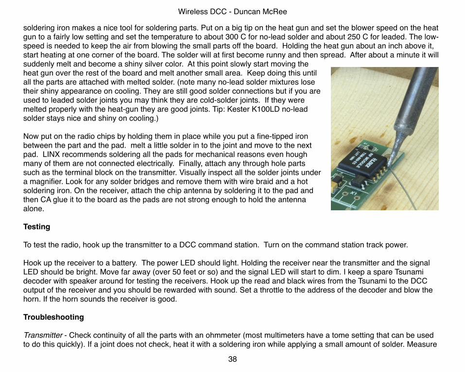
soldering iron makes a nice tool for soldering parts. Put on a big tip on the heat gun and set the blower speed on the heat gun to a fairly low setting and set the temperature to about 300 C for no-lead solder and about 250 C for leaded. The low-speed is needed to keep the air from blowing the small parts off the board. Holding the heat gun about an inch above it, start heating at one corner of the board. The solder will at first become runny and then spread. After about a minute it will suddenly melt and become a shiny silver color. At this point slowly start moving the heat gun over the rest of the board and melt another small area. Keep doing this until all the parts are attached with melted solder. (note many no-lead solder mixtures lose their shiny appearance on cooling. They are still good solder connections but if you are used to leaded solder joints you may think they are cold-solder joints. If they were melted properly with the heat-gun they are good joints. Tip: Kester K100LD no-lead solder stays nice and shiny on cooling.)
Now put on the radio chips by holding them in place while you put a fine-tipped iron between the part and the pad. melt a little solder in to the joint and move to the next pad. LINX recommends soldering all the pads for mechanical reasons even hough many of them are not connected electrically. Finally, attach any through hole parts such as the terminal block on the transmitter. Visually inspect all the solder joints under a magnifier. Look for any solder bridges and remove them with wire braid and a hot soldering iron. On the receiver, attach the chip antenna by soldering it to the pad and then CA glue it to the board as the pads are not strong enough to hold the antenna alone.
Testing
To test the radio, hook up the transmitter to a DCC command station. Turn on the command station track power.
Hook up the receiver to a battery. The power LED should light. Holding the receiver near the transmitter and the signal LED should be bright. Move far away (over 50 feet or so) and the signal LED will start to dim. I keep a spare Tsunami decoder with speaker around for testing the receivers. Hook up the read and black wires from the Tsunami to the DCC output of the receiver and you should be rewarded with sound. Set a throttle to the address of the decoder and blow the horn. If the horn sounds the receiver is good.
Troubleshooting
Transmitter - Check continuity of all the parts with an ohmmeter (most multimeters have a tome setting that can be used to do this quickly). If a joint does not check, heat it with a soldering iron while applying a small amount of solder. Measure
Wireless DCC - Duncan McRee
38
the output of the regulator with a voltmeter. It should read 5V. Check the 5V pin on the transmitter for the same reading. With a scope check that the data pin has a DCC signal on it at a 0-5 volt level. IF both of these check out then there is almost certainly a proper signal on the antenna.
Receiver - Check all the connections visually and with a continuity meter. Especially look at the inverter, U4. It is by far the hardest part to solder. Be very careful not to apply too much solder to the pins or they will from bridges. Measure the battery voltage. Measure the 5V pin on the receiver and verify it has 5V. If not check the voltage regulator U3. Measure the voltage on pin 3 of U2. It should be at the battery voltage. With a scope check the data output with the transmitter on and nearby. The receiver data pin (12) should be putting out 5V level DCC. With the scope check pins 6 and 7 on U2. They should both have 5V level DCC on them. If all these conditions are met, there should be DCC coming out of the receiver.
Wireless DCC - Duncan McRee
39
SourcesDRS1 System Sales and Installations
Mike’s BackshopAn expert in all types of Model Railroad radio installation from N to G scalesMike PfulbPhone 619-992-2234 E-Mail [email protected] Mikesbackshop.com
Lin's Junctionwww.linsjunction.com128 S. Line St., Linsdale, PA 19446Phone 215-412-7715
Litchfield Stationwww.litchfieldstation.com1412 N Central Ave Ste DAvondale AZ 85323-1316 USAPhone 623-298-7355
Parts Suppliers
Gold-plated Breakaway Connectors - I use these to make connections between the battery and the receiver. They are small, easy to plug and unplug and electrically reliable. Receptacle - Digi-Key SAM1115-32-ND. Header - Digi-Key SAM1111-32-ND.
Litium Polymer batteries - All RC stores that carry small electric airplanes and helicopters will have small 3-cell batteries. They can usually be made smaller by cutting off the heavy casing and adding a smaller connector made from breakaway headers (above). these batteries usually do not have circuit boards built in to them to protect them from over-charging and over-discharging. You can make your own 3-cell packs from these excellent batteries from SparkFun Electronics that do have the protective boards built-in: 400mAh LiPo. 110 mAh LiPo. Another source is All-battery.com - we like the 240 mAh Tenergy w/PCB.
Wireless DCC - Duncan McRee
40
Battery Charger. I like the HiTec X1. It can charge just about anything. It is not easy to use but then none of the better battery chargers are - they are just too complicated. I got mine by searching amazon.com but most RC stores have them and the helpful person behind the counter may be able to show you how to set it up to charge the battery you just bought.
Electronic Switch - You need a switch rated at least 1.5 Amps to turn the battery on and off. These can be quite big and bulky. An alternative is to use an electronic switch. This has a small momentary tactile switch that is used to toggle the power - Pololu Pushbutton Power Switch. I have mounted the pushbutton so that it can be toggled by a bamboo skewer through a small hole or window. The board has a green LED so you can tell when the power is on for locomotives without sound.
Reed Switch - An even better power switch can be made by replacing the pushbutton on the Pololu Power Switch with a small reed switch. You can then turn the power on and off with a small magnet. The reed switch can be hidden inside the shell. A small reed switch is available from Digi-Key 374-1083-ND. Small super magnets are available at hardware stores. I taped one to a small screwdriver to make my "magic wand" for turning my locomotives on and off.
Flexible Wire - TCS sells small very flexible 30 ga. wire in multiple colors. Also useful is solderable magnet wire from All Spectrum Electronics.
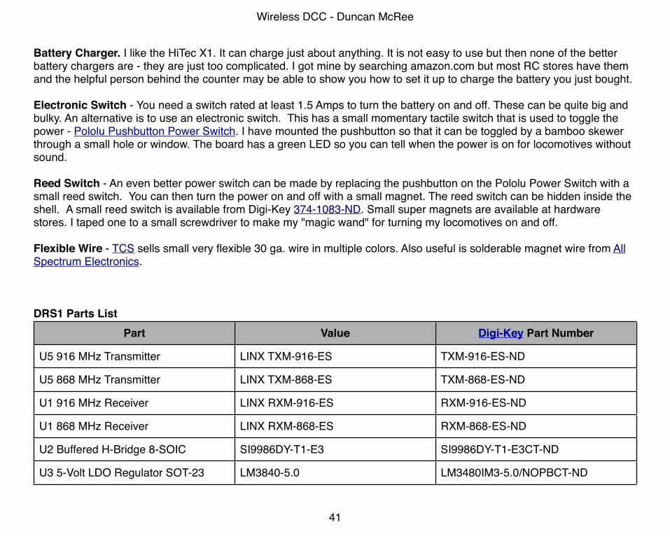
DRS1 Parts ListPart Value Digi-Key Part Number
U5 916 MHz Transmitter LINX TXM-916-ES TXM-916-ES-ND
U5 868 MHz Transmitter LINX TXM-868-ES TXM-868-ES-ND
U1 916 MHz Receiver LINX RXM-916-ES RXM-916-ES-ND
U1 868 MHz Receiver LINX RXM-868-ES RXM-868-ES-ND
U2 Buffered H-Bridge 8-SOIC SI9986DY-T1-E3 SI9986DY-T1-E3CT-ND
U3 5-Volt LDO Regulator SOT-23 LM3840-5.0 LM3480IM3-5.0/NOPBCT-ND
Wireless DCC - Duncan McRee
41
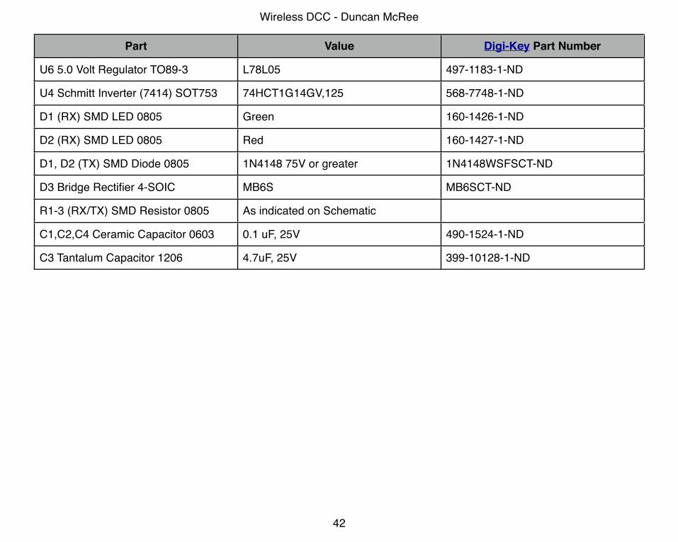
Part Value Digi-Key Part Number
U6 5.0 Volt Regulator TO89-3 L78L05 497-1183-1-ND
U4 Schmitt Inverter (7414) SOT753 74HCT1G14GV,125 568-7748-1-ND
D1 (RX) SMD LED 0805 Green 160-1426-1-ND
D2 (RX) SMD LED 0805 Red 160-1427-1-ND
D1, D2 (TX) SMD Diode 0805 1N4148 75V or greater 1N4148WSFSCT-ND
D3 Bridge Rectifier 4-SOIC MB6S MB6SCT-ND
R1-3 (RX/TX) SMD Resistor 0805 As indicated on Schematic
C1,C2,C4 Ceramic Capacitor 0603 0.1 uF, 25V 490-1524-1-ND
C3 Tantalum Capacitor 1206 4.7uF, 25V 399-10128-1-ND
Wireless DCC - Duncan McRee
42


