66
Wireless Ethernet IEEE 802.11 Standard Overview Dirk Grunwald Assoc. Professor Dept. of Computer Science University of Colorado, Boulder
| Date post: | 26-Dec-2015 |
| Category: |
Documents |
| Upload: | brendan-walters |
| View: | 216 times |
| Download: | 2 times |
Wireless EthernetIEEE 802.11 Standard
Overview
Dirk GrunwaldAssoc. Professor
Dept. of Computer ScienceUniversity of Colorado, Boulder
What’s Covered
High level overview of the 802.11 standard Motivation Organization Station Services MAC-level protocol Power Saving

Resources
Resources
IEEE 802 standards group http://grouper.ieee.org/groups/802/ 802.11 Specification is ~$450 or so
We have some copies

Differences Between WLANs and Wired LANs
Obviously, no wires Data is broadcast through free space, people can snoop Vagaries of electromagnetic propagation
Signals are not consistent Multipath and blocking may cause dead spots, even within open
areas
Mobility The problems that mobility brings
Problems Of Mobility
Orders of magnitude slower than fixed network Higher transmission bit error rates (BER) Uncontrolled cell population Difficult to ensure Quality of Service (QoS) Asymmetric duplex bandwidth Limited communication bandwidth exacerbates the
limitation of battery lifetime.
Limitations Imposed by Mobility
Lack of mobility-awareness by applications Inherently transparent programming model (object-,
components-oriented, but not aspect-oriented) Lack of environment test and set API support
Lack of mobility-awareness by the system network: existing transport protocols are inefficient to use
across heterogeneous mix of fixed/wireless networks session and presentation: inappropriate for the wireless
environment and for mobility operating systems: lack of env. related conditions and signals
• “you’ve lost your network” client/server: unless changed, inappropriate and inefficient

802.11 Design
Seemingly complex, but designed to overcome some of the complications of mobility
Components The station Access Point (AP) Wireless medium Basic Service Set (BSS) The Distribution System (DS) Extended Service Set (ESS) Station and Distribution Services

802.11 Design
Based on 802.2 LLC protocol Many similarities with other protocols Allows “seamless bridging” with other protocols using 802.2
LLC protocols
Supports variety of PHY IRDA 2.4 Ghz band
• 2 Mbit/s FHSS (802.11)• 1 / 2 / 5.5 / 11 Mbit/s DSSS (802.11b)
5.4 Ghz band• 24, 54 Mbit/s
The station
The station is a component that connects to the wireless medium
Consists of MAC and PHY Generally represented by a network interface card (NIC)
Station can be mobile, portable or stationary Each station supports station services such as
Authentication Deauthentication Privacy Deliver of Data Describe later..

The Basic Service Set
A BSS is a set of stations that communicate with one another
Does not refer to a physical area / region
If all the stations are mobile and there is no connection to a wired network, the BSS is called an independent BSS or IBSS
Also called “adhoc mode” IBSS is typically short-lived (“adhoc”)
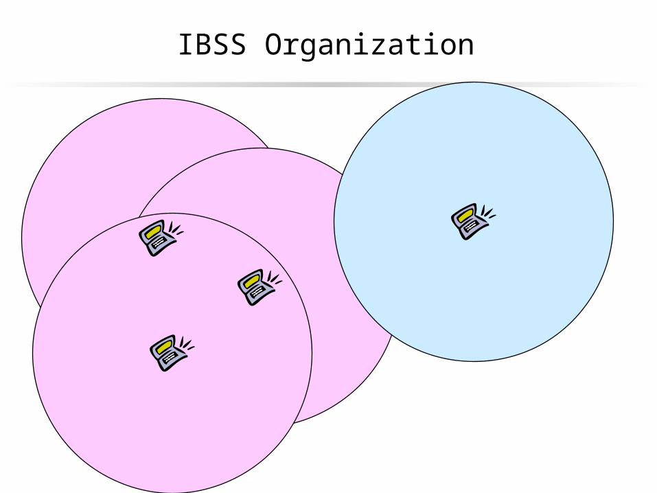
IBSS Organization

IBSS / Adhoc Organization
Stations send messages directly to other stations Only stations within the transmission range are “in the
IBSS”
There’s still an association / disassociation service
There is no centralized coordination for transmission
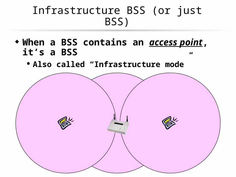
Infrastructure BSS (or just BSS)
When a BSS contains an access point, it’s a BSS Also called “Infrastructure mode”

Infrastructure BSS
In Infrastructure mode, each station sends messages only to the access point
The access point redistributes or retransmits the messages
Both on the wireless network and an associated wired network
Stations must associate with an access point and possibly authenticate themselves
The access point can control when stations transmit Power savings mode only possible when using an access point

Extended Service Set (ESS)
Extended Service Set
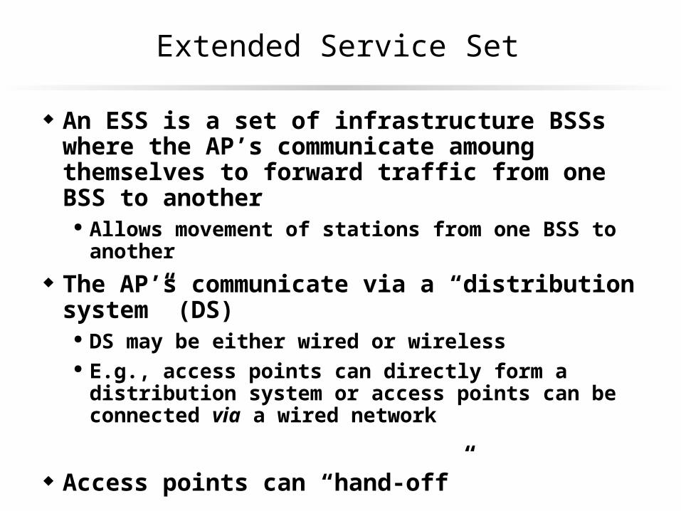
An ESS is a set of infrastructure BSSs where the AP’s communicate amoung themselves to forward traffic from one BSS to another
Allows movement of stations from one BSS to another
The AP’s communicate via a “distribution system” (DS) DS may be either wired or wireless E.g., access points can directly form a distribution system or
access points can be connected via a wired network
Access points can “hand-off”

Extended Service Set (ESS)
Router

Inter-ESS Coordination
Inter-Access Point Protocol Not part of 802.11 & no documentation available But not rocket science – access points know the IP address of
different access points. Access points inform other access points when a station associates. Maps are maintained and messages forwarded
Bridging Must be on same subnet If a destination is a broadcast or
unknown MAC address, the AP sendsit to the wired network
AP records MAC for all stations,grabs all frames with those MACs
A
B
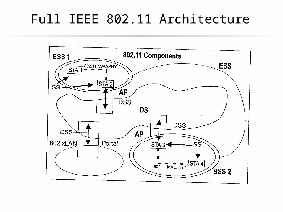
Full IEEE 802.11 Architecture

Station Services
Authentication – used to prove identity of one station to another
Deauthentication – eliminate previous authorized user from use of network (security revocation)
Privacy – wired equivalent privacy, similar to that of in-wall wiring
Data Delivery – reliable deliver of data frames from one MAC to another, with minimal duplication or reordering
Distribution Services
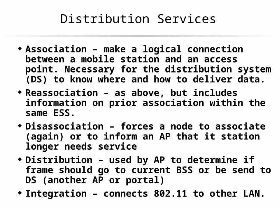
Association – make a logical connection between a mobile station and an access point. Necessary for the distribution system (DS) to know where and how to deliver data.
Reassociation – as above, but includes information on prior association within the same ESS.
Disassociation – forces a node to associate (again) or to inform an AP that it station longer needs service
Distribution – used by AP to determine if frame should go to current BSS or be send to DS (another AP or portal)
Integration – connects 802.11 to other LAN.

Association & Authentication
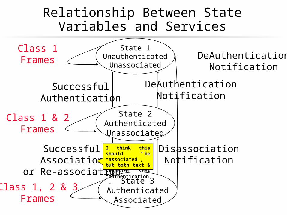
Each station must maintain two state variables for each other station with which it communicates
Each station may be authenticated with many stations at the same time, but is associated with only one at a time.
There are three classes of frame types – the station must respond to certain classes in different connection states.
Relationship Between State Variables and Services
State 1Unauthenticated
Unassociated
State 3Authenticated
Associated
State 2AuthenticatedUnassociated
SuccessfulAuthentication
SuccessfulAssociation
or Re-association
Class 1Frames
Class 1 & 2Frames
Class 1, 2 & 3Frames
DisassociationNotification
DeAuthenticationNotification
DeAuthenticationNotification
I think this should be “associated”, but both text & standard show “authentication”.
Messages
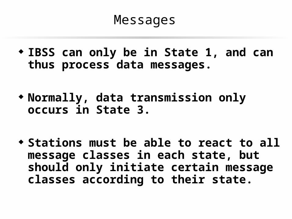
IBSS can only be in State 1, and can thus process data messages.
Normally, data transmission only occurs in State 3.
Stations must be able to react to all message classes in each state, but should only initiate certain message classes according to their state.

MAC Layer Functions
Provide reliable data delivery Hidden node & exposed node problem Solutions
Fairly control access to shared media Distributed coordination function Point coordination function
Protect the data that is delivered WEP
Wireless Ethernet Is Not Ethernet
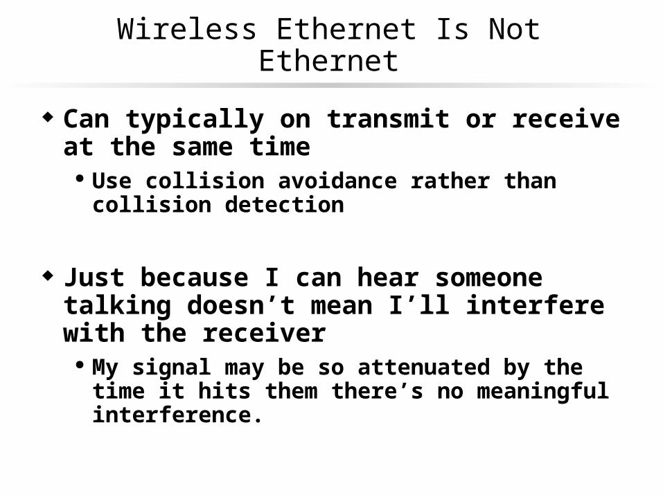
Can typically on transmit or receive at the same time Use collision avoidance rather than collision detection
Just because I can hear someone talking doesn’t mean I’ll interfere with the receiver
My signal may be so attenuated by the time it hits them there’s no meaningful interference.

Hidden Node Problem In CSMA
A B C
A B C

Exposed Node Problem In CSMA
A B C D
A B C D
802.11 MACA Protocol
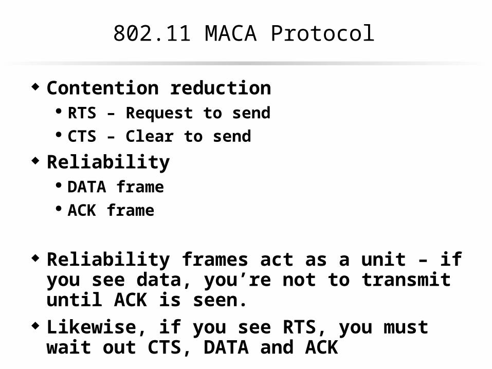
Contention reduction RTS – Request to send CTS – Clear to send
Reliability DATA frame ACK frame
Reliability frames act as a unit – if you see data, you’re not to transmit until ACK is seen.
Likewise, if you see RTS, you must wait out CTS, DATA and ACK
802.11 MA/CA
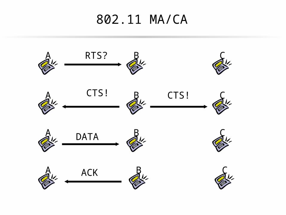
A B CRTS?
A B CCTS! CTS!
A B CDATA
A B CACK
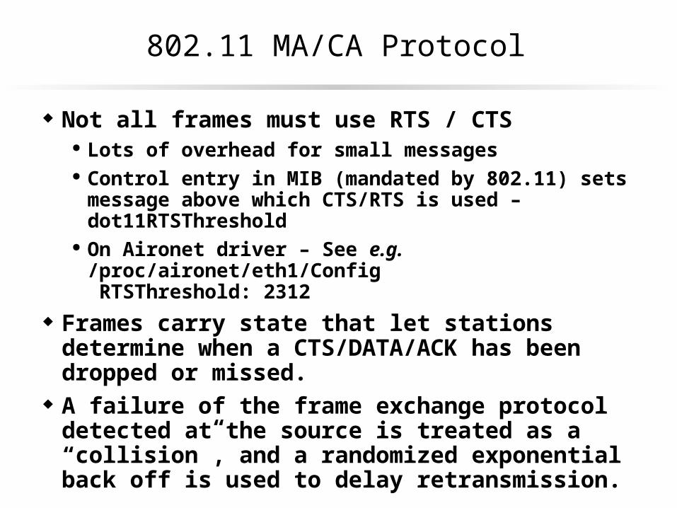
802.11 MA/CA Protocol
Not all frames must use RTS / CTS Lots of overhead for small messages Control entry in MIB (mandated by 802.11) sets message above
which CTS/RTS is used – dot11RTSThreshold On Aironet driver – See e.g. /proc/aironet/eth1/Config
RTSThreshold: 2312
Frames carry state that let stations determine when a CTS/DATA/ACK has been dropped or missed.
A failure of the frame exchange protocol detected at the source is treated as a “collision”, and a randomized exponential back off is used to delay retransmission.
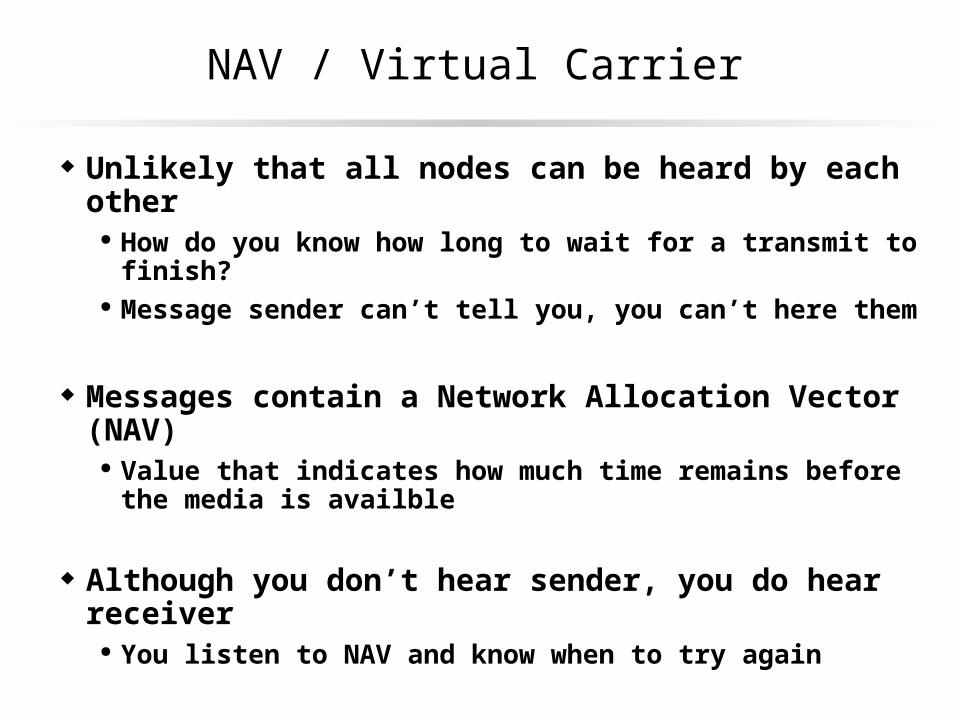
NAV / Virtual Carrier
Unlikely that all nodes can be heard by each other How do you know how long to wait for a transmit to finish? Message sender can’t tell you, you can’t here them
Messages contain a Network Allocation Vector (NAV) Value that indicates how much time remains before the media is
availble
Although you don’t hear sender, you do hear receiver You listen to NAV and know when to try again

Timeline of RTS / CTS & NAV
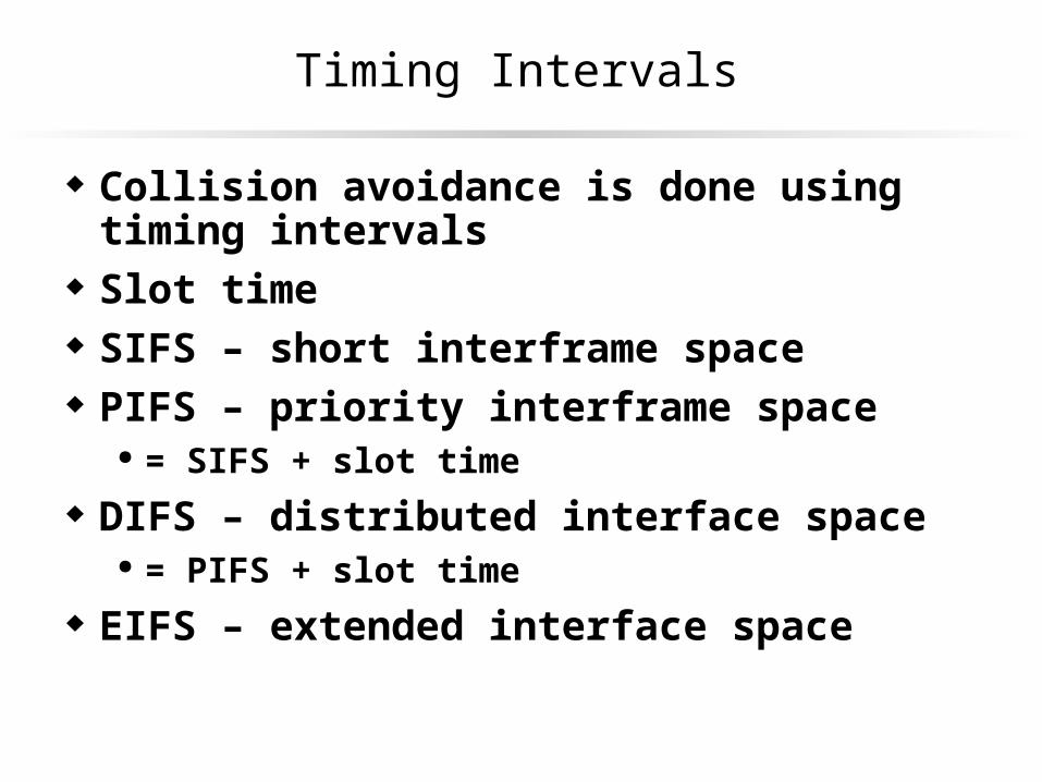
Timing Intervals
Collision avoidance is done using timing intervals Slot time SIFS – short interframe space PIFS – priority interframe space
= SIFS + slot time
DIFS – distributed interface space = PIFS + slot time
EIFS – extended interface space

Some IFS Relationships
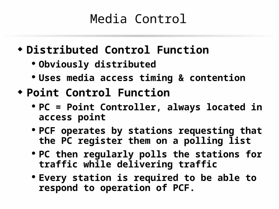
Media Control
Distributed Control Function Obviously distributed Uses media access timing & contention
Point Control Function PC = Point Controller, always located in access point PCF operates by stations requesting that the PC register them
on a polling list PC then regularly polls the stations for traffic while delivering
traffic Every station is required to be able to respond to operation of
PCF.
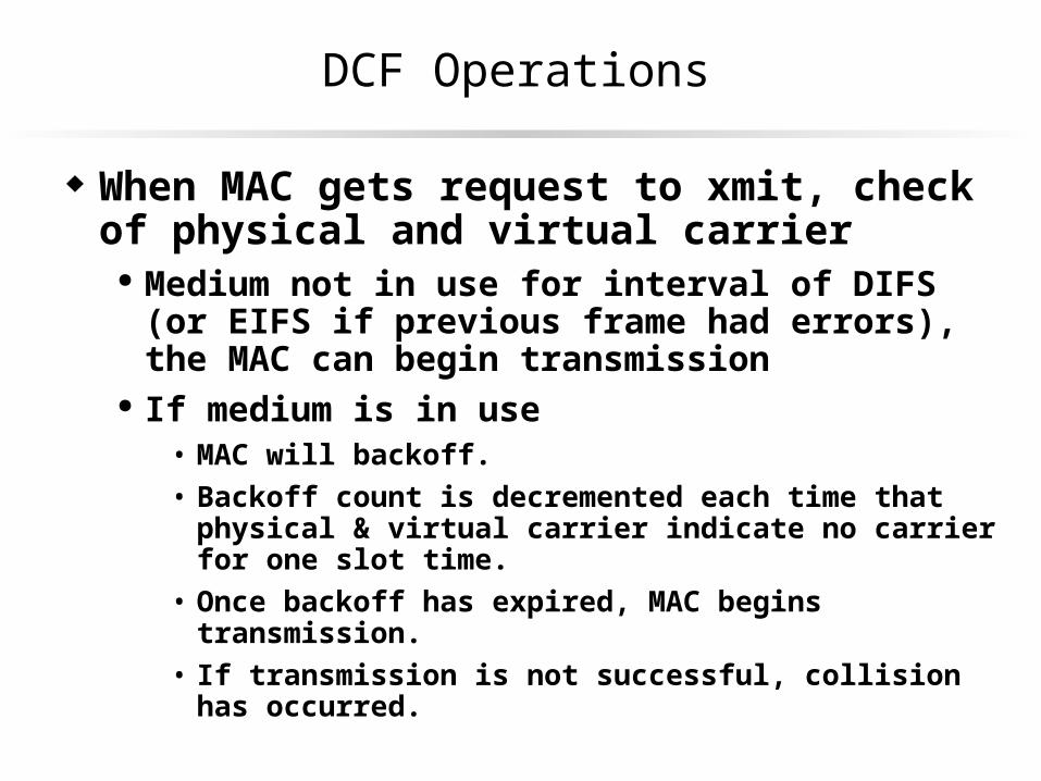
DCF Operations
When MAC gets request to xmit, check of physical and virtual carrier
Medium not in use for interval of DIFS (or EIFS if previous frame had errors), the MAC can begin transmission
If medium is in use• MAC will backoff.• Backoff count is decremented each time that physical & virtual carrier
indicate no carrier for one slot time.• Once backoff has expired, MAC begins transmission.• If transmission is not successful, collision has occurred.

Model of Contention in DCF Mode
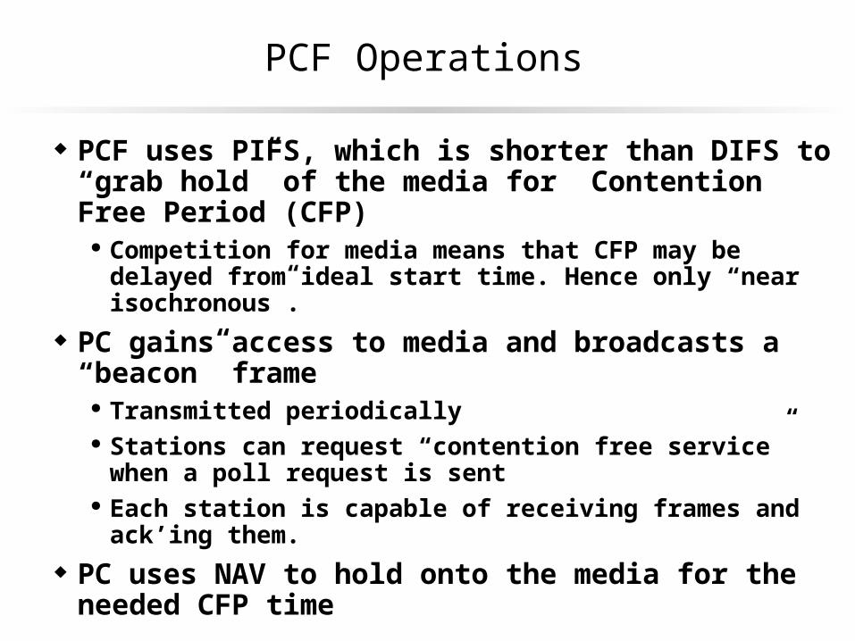
PCF Operations
PCF uses PIFS, which is shorter than DIFS to “grab hold” of the media for Contention Free Period (CFP)
Competition for media means that CFP may be delayed from ideal start time. Hence only “near isochronous”.
PC gains access to media and broadcasts a “beacon” frame
Transmitted periodically Stations can request “contention free service” when a poll
request is sent Each station is capable of receiving frames and ack’ing them.
PC uses NAV to hold onto the media for the needed CFP time

PC Polling
PC sends a “contention free poll” (CF-Poll) to stations requesting contention-free service
If station has traffic, it may send one frame for each CF-Poll
Can piggy back both ACK and the CF-Poll on data frames during CFP
“PC Can combine CF-Poll and ACK with data frame as well”hence, PC may be sending a frame to one station, along with a CF-Poll and ACK a frame received from an entirely different station.

Holding Media in PCF
NAV is primary mechanism to hold media Announced in Beacon at beginning of CFP
PIFS is secondary mechanism in case some station did not hear Beacon
During CFP, PC assures no interval on medium less than PIFS. If response not received within SIFS, PC will send frame before
PIFS expires
PC announces end of CF period using a CF-End frame Once NAV is reset, stations compete using DCF
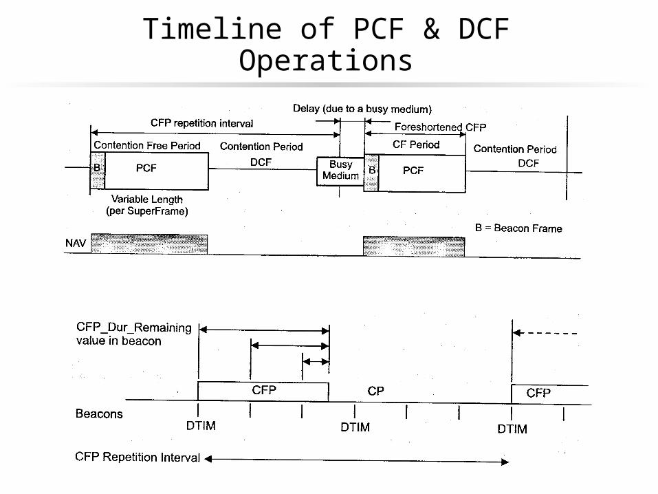
Timeline of PCF & DCF Operations
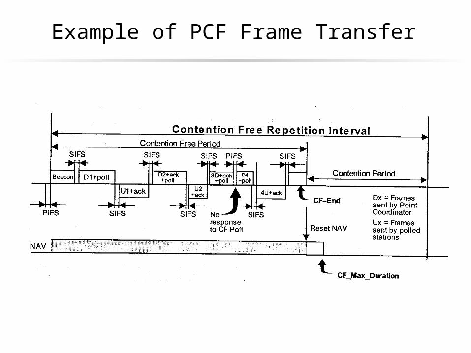
Example of PCF Frame Transfer

Station Identifiers
SSID is the service set identify 32 byte “network name” Zero length “name” is broadcast (I.e. any network)
BSSID is the Basic Service Set ID Shorter numeric value, randomly generated
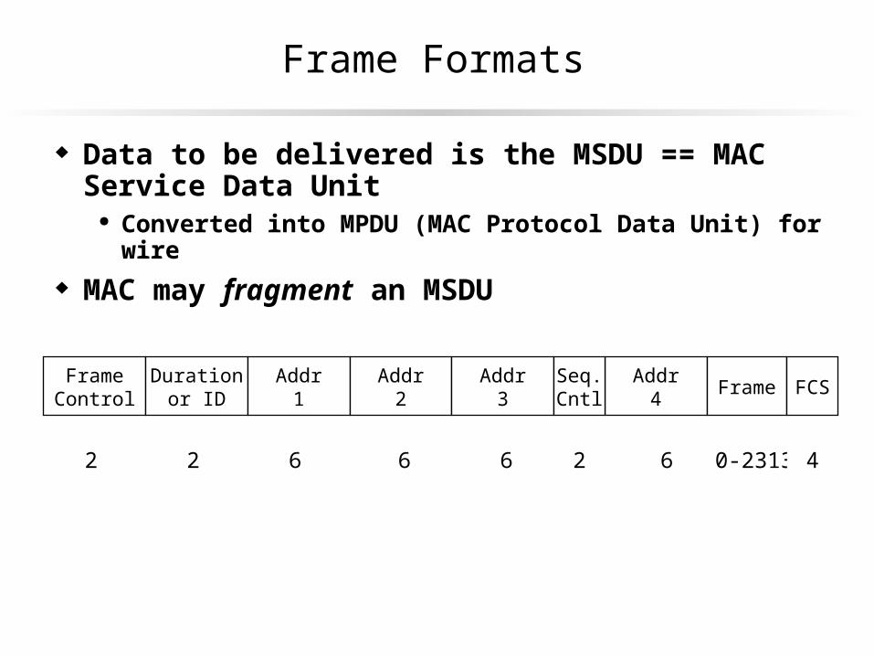
Frame Formats
Data to be delivered is the MSDU == MAC Service Data Unit Converted into MPDU (MAC Protocol Data Unit) for wire
MAC may fragment an MSDU
Addr4
FrameControl
Durationor ID
Addr1
Addr2
Addr3
2
Seq.Cntl Frame FCS
2 6 6 6 2 6 0-2313 4
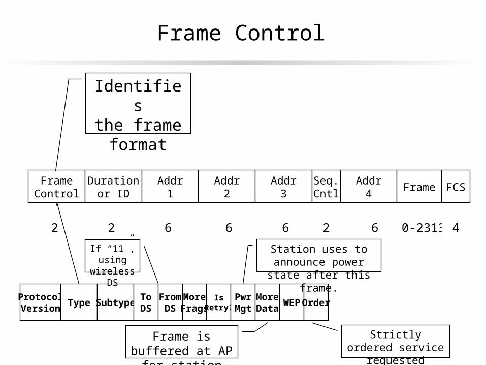
Frame Control
Addr4
FrameControl
Durationor ID
Addr1
Addr2
Addr3
2
Seq.Cntl Frame FCS
2 6 6 6 2 6 0-2313 4
Identifiesthe frame
format
ProtocolVersion
Type SubtypeToDS
FromDS
MoreFrags
IsRetry?
PwrMgt
MoreData
WEP Order
If “11”, using wireless DS
Station uses to announce power state after this frame.
Frame is buffered at AP for station
Strictly ordered service requested
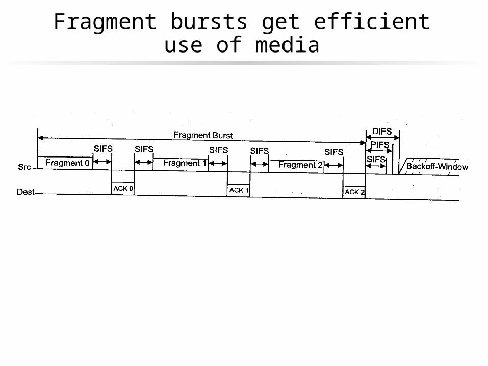
Fragment bursts get efficient use of media
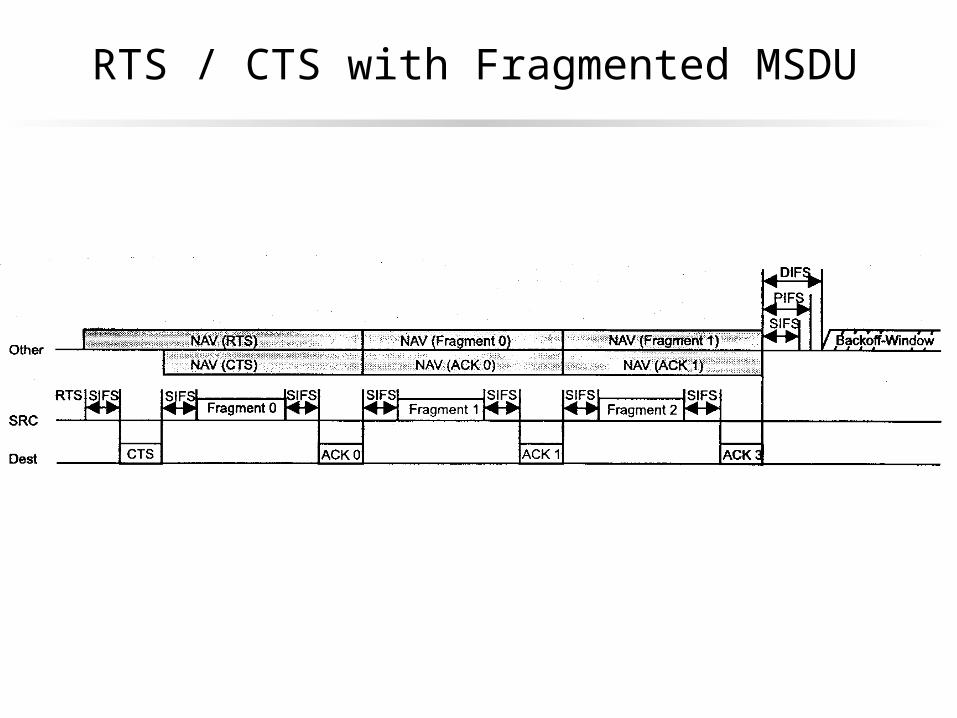
RTS / CTS with Fragmented MSDU
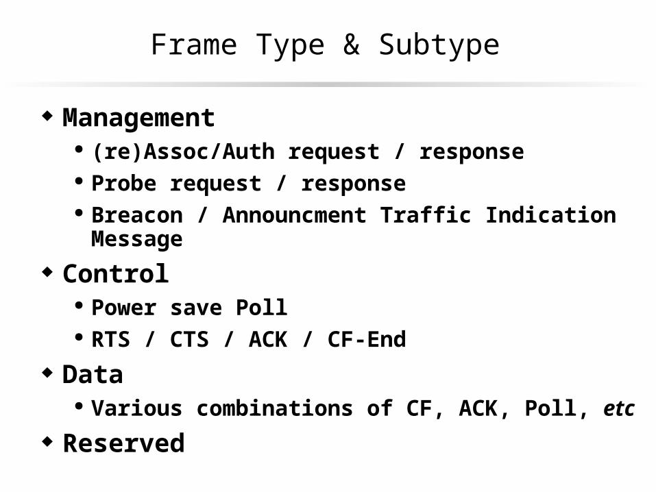
Frame Type & Subtype
Management (re)Assoc/Auth request / response Probe request / response Breacon / Announcment Traffic Indication Message
Control Power save Poll RTS / CTS / ACK / CF-End
Data Various combinations of CF, ACK, Poll, etc
Reserved
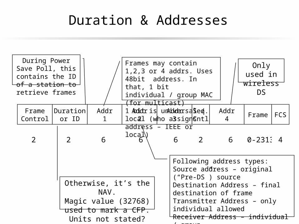
Duration & Addresses
Addr4
FrameControl
Durationor ID
Addr1
Addr2
Addr3
2
Seq.Cntl Frame FCS
2 6 6 6 2 6 0-2313 4
During Power Save Poll, this contains the ID of a station to retrieve frames
Otherwise, it’s the NAV.Magic value (32768) used to
mark a CFP. Units not stated?
Following address types:Source address – original (“Pre-DS”) sourceDestination Address – final destination of frameTransmitter Address – only individual allowedReceiver Address – individual / groupBSS Identifier – unique ID for BSS. MAC of AP if infrastructure, else local random address.
Frames may contain 1,2,3 or 4 addrs. Uses 48bit address. In that, 1 bit individual / group MAC (for multicast)1 bit is universal / local (who assigns address – IEEE or local)
Only used in wireless DS
Power Save Poll
PS poll is 20 bytes Purpose is to request an AP to deliver frames that are
queued on the AP while station was in power save mode.
BSSID identifies AP to which poll is directed (should be associated device)
Beacon Frames
Transmitted periodically to allow mobile stations to locate and identify a BSS
Allows device to the BSS (in time & PHY) at any time I.e., sync clocks & select media
Allows conveys info about buffered frames Frame contains
Timestamp of stations synchronization timer when frame was transmitted
Beacon interval Capabilities – SSID, supported rates, one or more PHY
parameter sets, optional CFP parameter set, optional IBSS parameter set and optional traffic indication map
Probe Request / Response
Used to locate a WLAN with a particular SSID or to locate any WLAN at all.
Contains SSID of requested WLAN Supported rates
In BSS, AP will always respond to beacon In IBSS, station that send last beacon will respond Probe frame contains almost all the same info as a
beacon frame
Traffic Indication Map (TIM)
May be from 6 to 256 bytes Carries information about frames that are buffered at AP AP buffers all multicast when there are any stations
operating in low power mode. DTIM (Delivery TIM) inform mobile stations when
multicast frames that have been buffered at AP will be delivered and how often that delivery will occur. Value is in terms of beacon frames
There’s also a bitmask, indexed by an Association ID (AID) that is assigned at Assoc. Used to indicate if station has messages waiting.

Security (WEP)
2 mechanisms Set of up to 4 default keys shared by all stations
Distributed to all stations
“Key Mapping” relationship with another station Key mapping lets you create a key used only with a single other
station. Not required in standard.
Authentication
Normally between station & AP 2 Mechanisms “Open System Authentication”
For people who do not use WEP Authentication always works
“Shared Key Authentication” Shared WEP key Uses WEP to encrypt and decrypt a “challenge text” Mobile station A sends identity assertion to B, B sends text to
A, A encrypts, returns to B, B decrypts and returns success / failure.
Only authenticates A to B, not B to A.
Hacking Authentication
Rogue could adopt SSID of the ESS Announce presence through beacon Stations attempt to authenticate Rogue always replies with success

Association
Association request includes information on the capabilities of a station, etc.
Policies and standards for accepting an association not specified in standard

Power Management in IBSS
Power management fully distributed in IBSS Station enters low power mode turns of receiver and
transmitter Must complete handshake with any other station and set the
power mode bit
Station must awake to receive every beacon Must stay away after the beacon to receive the ATIM
(adhoc traffic announcement message window) Other stations announce frames during that window
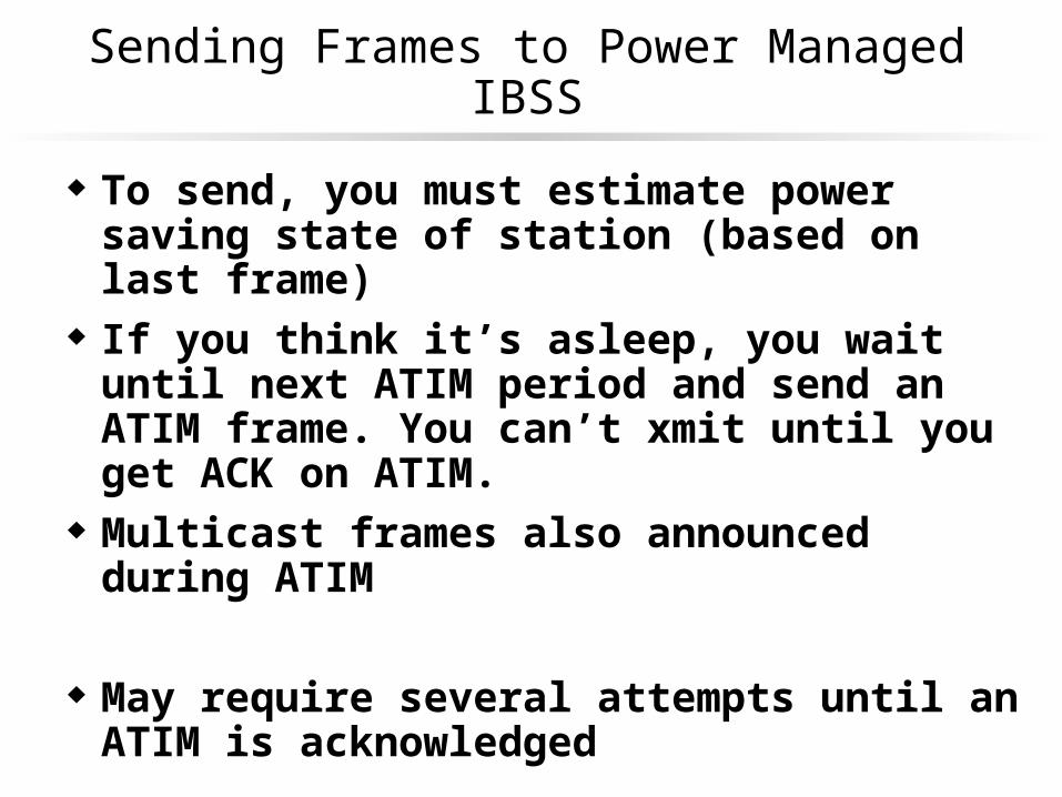
Sending Frames to Power Managed IBSS
To send, you must estimate power saving state of station (based on last frame)
If you think it’s asleep, you wait until next ATIM period and send an ATIM frame. You can’t xmit until you get ACK on ATIM.
Multicast frames also announced during ATIM
May require several attempts until an ATIM is acknowledged
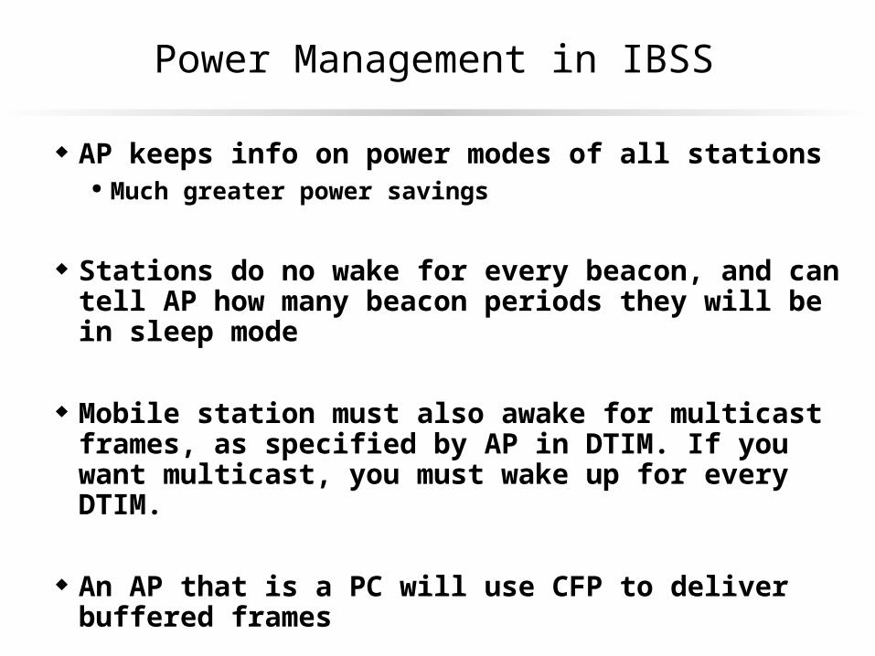
Power Management in IBSS
AP keeps info on power modes of all stations Much greater power savings
Stations do no wake for every beacon, and can tell AP how many beacon periods they will be in sleep mode
Mobile station must also awake for multicast frames, as specified by AP in DTIM. If you want multicast, you must wake up for every DTIM.
An AP that is a PC will use CFP to deliver buffered frames
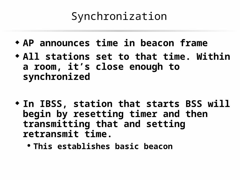
Synchronization
AP announces time in beacon frame All stations set to that time. Within a room, it’s close
enough to synchronized
In IBSS, station that starts BSS will begin by resetting timer and then transmitting that and setting retransmit time.
This establishes basic beacon

Beacon Transmission in IBSS
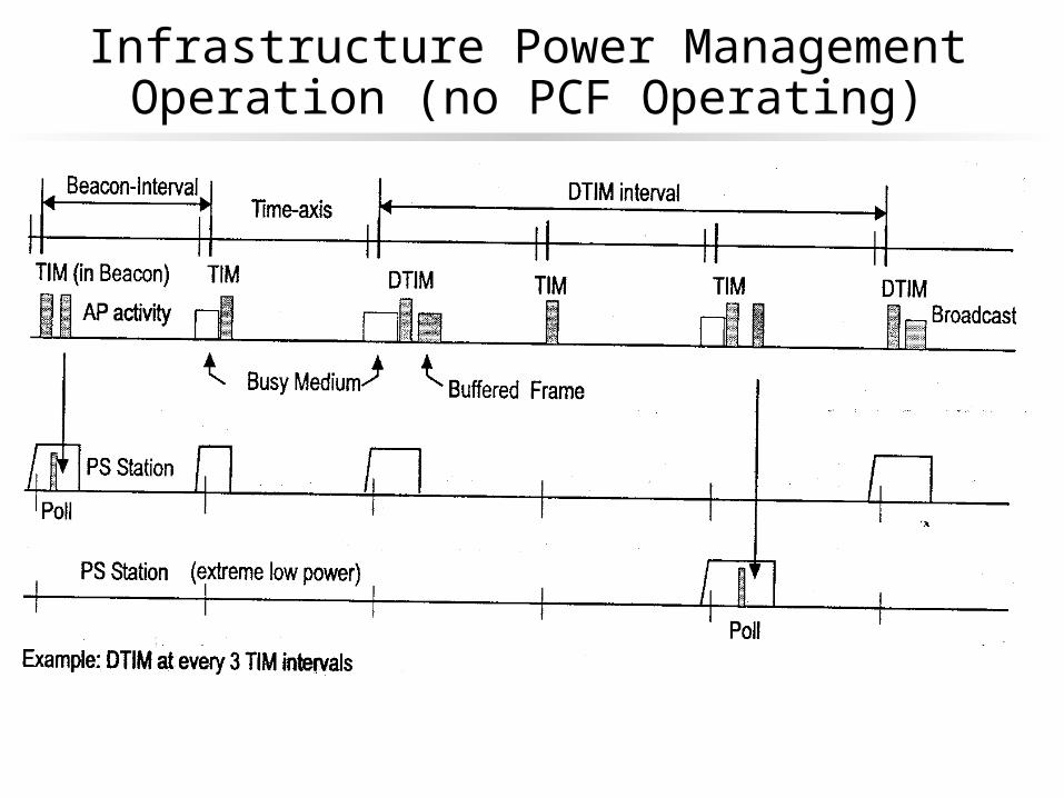
Infrastructure Power Management Operation (no PCF Operating)

Power Management in an IBSSBasic Operation


