Page 1
Wireless Intrusion Detection System
Using
FingerPrinting
Manish Sachdev
Department of Computer Science and Engineering
National Institute of Technology Rourkela
Rourkela-769008, Odisha, India
May 2014
Page 2
Wireless Intrusion Detection System
Using
FingerPrinting
Thesis submitted in partial fulfillment of the requirements for the degree of
Master of Technology
in
Computer Science and Engineering(Specialization: Information Security)
by
Manish Sachdev(Roll No.- 212CS2367)
under the supervision of
Prof. S. K. Jena
Department of Computer Science and Engineering
National Institute of Technology Rourkela
Rourkela, Odisha, 769 008, India
MAY 2014
Page 3
Department of Computer Science and EngineeringNational Institute of Technology RourkelaRourkela-769 008, Odisha, India.
Certificate
This is to certify that the work in the thesis entitled Wireless Intrusion De-
tection System using FingerPrinting by Manish Sachdev is a record of
an original research work carried out by him under my supervision and guidance
in partial fulfillment of the requirements for the award of the degree of Master
of Technology with the specialization of Information Security in the department
of Computer Science and Engineering, National Institute of Technology Rourkela.
Neither this thesis nor any part of it has been submitted for any degree or academic
award elsewhere.
Place: NIT Rourkela (Prof. S. K. Jena)Date: May 31, 2014 Professor, CSE Department
NIT Rourkela, Odisha
Page 4
Author’s Declaration
I hereby declare that all work contained in this report is my own work unless
otherwise acknowledged. Also, all of my work has not been submitted for any
academic degree. All sources of quoted information has been acknowledged by
means of appropriate reference.
Place: NIT Rourkela (Manish Sachdev)Date: May 31, 2014 M.Tech, 212cs2367, CSE Department
NIT Rourkela, Odisha
Page 5
Acknowledgment
Writing of thesis is a journey through gravel road, but you can make it with the
help of the people and resources you get in touch through out your journey. I am
thankful to all of these peers who have contributed towards shaping this thesis.
First of all, I would like to express my sincere thanks to Prof. S. K. Jena for his
observations and advice during my thesis work constantly encouraged me to estab-
lish the overall direction to the research and to move forward with investigation
in depth. He has helped me greatly and been a source of knowledge and my road
become straight and easier to go. I am also thankful to all the professors at the
department for their support. I would also like to special thank to Asish Dalai
Sir, PhD Scholar at NIT Rourkela, for their help and support to clear my hurdles
and understanding. I would like to thank all my friends and lab-mates for their
encouragement and understanding. Their help can never be penned with words.
One of the most important acknowledgment is for the academic resources that I
have got from NIT Rourkela. I would like to thank administrative and technical
staff members of the Department who have been kind enough to advise and help
in their respective roles. Last, but not the least, I would like to dedicate this
thesis to my Mom and Dad for their love, patience, and understanding.
Manish Sachdev
Roll No-212CS2367
Page 6
Abstract
Wireless network is the network which is easy to deploy and very easy to
access that network and that network is user friendly. The main reason behind of
getting popular is because it provide benefits, like as easy to installation, flexibility,
mobility, scalability and reduced cost-of-ownership. But drawback in these wireless
networks is that it doesn’t provide security as much as required, due to that user
faces attacks of various types which are damageable to user informations. One of
the serious attack is Identity based attacks which steals the identity of some other
user in that network and performed some other attack. The available present
security tools to detect such these identity(spoofed MAC) based attacks are quite
limited.
In this proposed work a new technique is developed for detecting masquer-
ade(identity) attacks or spoofed MAC attack exploited in 802.11 wireless network.
Current methods of device fingerprinting includes only probe request packets fin-
gerprinting, which results in large amount of false positive. In our proposed work
fingerprint is created on basis of three frames which are required in three section of
connectivity phase and that frames are probe request frame, authentication frame
and association frame. Time differences between consecutive frames are take into
consideration and on the basis of that fingerprint is created of different device. In
this proposed technique cross-correlation method is used to estimate the signals
similarity in terms of time lagging to each other. Those signals are captured by
different devices. Stored signature of actual device and captured signal of trans-
mitting device is compared using this technique and after that result analysis,
identification of device is done.
Keywords: Masquerade Attacks,Device FingerPrinting, Probe-request, au-
thentication request and association request, cross-correlation.
Page 7
Contents
Certificate ii
Declaration iii
Acknowledgement iv
Abstract v
List of Figures viii
List of Tables ix
1 Introduction 2
1.1 Wireless Networking Basics . . . . . . . . . . . . . . . . . . . . . . 4
1.2 802.11 WLAN . . . . . . . . . . . . . . . . . . . . . . . . . . . . . . 4
1.2.1 802.11 Protocol . . . . . . . . . . . . . . . . . . . . . . . . . 4
1.2.2 WLAN Components . . . . . . . . . . . . . . . . . . . . . . 5
1.2.3 WLAN Connection Process . . . . . . . . . . . . . . . . . . 7
1.2.4 802.11 authentication model . . . . . . . . . . . . . . . . . . 10
1.2.5 IEEE 802.11 Rate Adaptation . . . . . . . . . . . . . . . . . 11
1.3 Address Resolution Protocol . . . . . . . . . . . . . . . . . . . . . . 12
1.4 MAC Layer Attacks . . . . . . . . . . . . . . . . . . . . . . . . . . . 13
1.4.1 ARP Poisoning Attack . . . . . . . . . . . . . . . . . . . . . 13
1.4.2 Denial of service (DoS) or Distributed Denial of service (DDoS)
attack . . . . . . . . . . . . . . . . . . . . . . . . . . . . . . 14
1.4.3 Man-In-The-Middle Attack . . . . . . . . . . . . . . . . . . . 15
1.5 Security Solutions Basics . . . . . . . . . . . . . . . . . . . . . . . . 15
1.5.1 802.11 Management frames FingerPrinting . . . . . . . . . . 15
1.5.2 Sequence Numbers . . . . . . . . . . . . . . . . . . . . . . . 17
vi
Page 8
1.5.3 Signal Strength . . . . . . . . . . . . . . . . . . . . . . . . . 18
1.6 Intrusion Detection Systems . . . . . . . . . . . . . . . . . . . . . . 19
1.7 Summary . . . . . . . . . . . . . . . . . . . . . . . . . . . . . . . . 20
1.8 Thesis Organization . . . . . . . . . . . . . . . . . . . . . . . . . . . 20
2 Literature Review 23
2.1 Summary . . . . . . . . . . . . . . . . . . . . . . . . . . . . . . . . 29
3 Proposed Technique and Simulation 32
3.1 Introduction . . . . . . . . . . . . . . . . . . . . . . . . . . . . . . . 32
3.2 Our Proposed Technique . . . . . . . . . . . . . . . . . . . . . . . . 33
3.2.1 Spoofed Wireless Device Detection using Management Frames
Fingerprinting . . . . . . . . . . . . . . . . . . . . . . . . . . 33
3.2.2 Basics Behind Proposed Technique . . . . . . . . . . . . . . 34
3.2.3 Proposed Technique . . . . . . . . . . . . . . . . . . . . . . 36
3.3 Implementation . . . . . . . . . . . . . . . . . . . . . . . . . . . . . 38
3.3.1 Experimental Setup . . . . . . . . . . . . . . . . . . . . . . . 38
3.3.2 Required Equipment . . . . . . . . . . . . . . . . . . . . . . 38
3.3.3 Required Software . . . . . . . . . . . . . . . . . . . . . . . 38
3.3.4 Complete Detailed Process . . . . . . . . . . . . . . . . . . . 39
3.3.5 Results . . . . . . . . . . . . . . . . . . . . . . . . . . . . . . 42
3.4 Summary . . . . . . . . . . . . . . . . . . . . . . . . . . . . . . . . 47
4 Conclusion And Future Scope 49
4.1 Conclusion . . . . . . . . . . . . . . . . . . . . . . . . . . . . . . . . 49
4.2 Future Scope . . . . . . . . . . . . . . . . . . . . . . . . . . . . . . 49
Bibliography 51
Page 9
List of Figures
1.1 802.11 and OSI Model . . . . . . . . . . . . . . . . . . . . . . . . . 5
1.2 Connection Phases . . . . . . . . . . . . . . . . . . . . . . . . . . . 8
1.3 Association Process . . . . . . . . . . . . . . . . . . . . . . . . . . . 9
1.4 802.11 authentication model [1] . . . . . . . . . . . . . . . . . . . . 11
3.1 MAC Layer Packet Structure [2] . . . . . . . . . . . . . . . . . . . . 34
3.2 Probe request timing estimation for atheros ar 9485 NIC card . . . 42
3.3 Probe request timing estimation for DW1520 Half-Mini card NIC
card . . . . . . . . . . . . . . . . . . . . . . . . . . . . . . . . . . . 43
3.4 Authentication Request relative time estimation after each probe
response for atheros ar-9485 . . . . . . . . . . . . . . . . . . . . . . 43
3.5 Authentication Request relative time estimation after each probe
response for DW1520 Half-Mini card . . . . . . . . . . . . . . . . . 44
3.6 Association Request relative time estimation after each authentica-
tion response for atheros ar-9485 . . . . . . . . . . . . . . . . . . . 44
3.7 Association Request relative time estimation after each authentica-
tion response for DW1520 Half-Mini card . . . . . . . . . . . . . . . 45
3.8 Cross correlation estimation for probe request between atheros NIC
and DW1520 Half-Mini card . . . . . . . . . . . . . . . . . . . . . . 46
3.9 Cross correlation estimation for Authentication request signal be-
tween atheros NIC and DW1520 Half-Mini card . . . . . . . . . . . 46
3.10 Cross correlation estimation for Association request signal between
atheros NIC and DW1520 Half-Mini card . . . . . . . . . . . . . . . 47
viii
Page 10
List of Tables
1.1 802.11 standard family [3] . . . . . . . . . . . . . . . . . . . . . . . 4
3.1 802.11 Management Frames [4] . . . . . . . . . . . . . . . . . . . . 35
3.2 802.11 Control Frames [4] . . . . . . . . . . . . . . . . . . . . . . . 36
3.3 Management frames usable fields . . . . . . . . . . . . . . . . . . . 37
ix
Page 11
Introduction
Wireless Networking Basics
802.11 WLAN
Address Resolution Protocol
MAC Layer Attacks
SecuritySolutions Basics
Intrusion Detection System
Summary
Thesis Organizations
Page 12
Chapter 1
Introduction
Wireless LANs(local area network) are hard and difficult and hard to provide
stronger security as compared to wired local area network(WLANs), main reason
behind these weakness and possibility of attacks is the fact that, these network
can be accessed by anyone because wireless signals may goes beyond the physical
boundaries. It is not possible to stop the signal to go out of organization or
specified boundaries .
Today IEEE 802.11 Wireless LAN(WLAN) [5] got so much popularity which
makes it target for attacks and hackers broke the security for unauthorized access.
IEEE 802.11 has certain weakness and vulnerabilities in design of MAC protocol
which gives more power to hacker to do some big attacks on WLAN. [6]
There are some workstations available which work as a WLAN monitoring
systems that observe the nature of network traffic and detect possible and likely
attacks in real time. This nature of monitoring system contribute their part in
security and robustness of WLAN networks.
There are some already present network-based intrusion detection system [7] [8]
which works on IP layer or above and identify an attack that misuse the avail-
able weakness of the network and exploit that vulnerability. NIDS(network-based
intrusion detection system) [7] [8] identifies the attack irrespective of transfer
of packet either through wired network or wireless network. In present, attacks
which are hard to detectable by presently available network-based intrusion detec-
tion systems are mostly due to weakness of data link-layer protocol vulnerabilities.
Some internal properties of IEEE 802.11 WLAN gave a lot of security challenges
2
Page 13
Introduction
kind of access of network resources and services after breaching the authorization,
promiscuously sniffing of information traveling in that network off the air, identity
attacks, denial of service attack, rogue access points, session hijacking attacks and
ARP poisoning all are made easier after exploiting the vulnerabilities of data link-
layer [9] [10] [11] . In all these attacks DoS(denial of service) or distributed DoS is
the kind of attack to perform in which attacker tries to interrupt the availability
of WLAN services to the client. These attacks are easy to performed because
physical address(MAC address) of NIC(network interface controller) is very easy
to make modification in it and that process is called spoofing of MAC address.
These spoofing based attacks are specifically dangerous, because these attack hide
the identity of actual user and give power to user to perform major attacks.
Today Many organizations by yourself use authentication on application layer,
used only into organization campus as IDs and their passwords. Difficulty occur
in this approach is that authenticate users credentials are not associated tightly
to that client. Here is the case that there is possibility an authenticated user can
give his/her ID and password to another user who may be not authenticate to the
network and wants access to that network without authenticated ID and password.
In the other cases the authenticated user may be cheated into disclosing his/her
Id and password through phishing technique [12] [13] [37].
There are some more risk excluding above risks that there is notable important
affect of authorized users,who bring unauthorized machines to bring the possibility
of harm the network by introducing processes which further introduce malicious
activity. [13]
The easily perceived solution is to give authentication assistance to each and
every data frame together with control and management frames transmitted from
source. Although IEEE 802.11i provide privacy and authentication standard to
only data frames not for control and management frames. [6]
3
Page 14
1.1 Wireless Networking Basics Introduction
1.1 Wireless Networking Basics
The basic technologies of wireless network systems.
1.2 802.11 WLAN
A wireless local area network (WLAN) is a kind of data communication service
providing technique in which that network can use either radio frequency technol-
ogy or infrared technology to make transmission of information and also receiving
information over the air. 802.11 standard was implemented and installed as the
first Wireless LAN standard and it is based on technology which operates in fre-
quency level of 2.4 GHz and it provides throughput maximum of 1Mbps to 2
Mbps. Today the most used deployment standard is IEEE standard 802.11b and
it operates in the frequency range which is same as past 802.11 standards, but it
provides speed of maximum of 11 Mbps. [3]
Table 1.1: 802.11 standard family [3]
Protocol Frequency(GHz)
Typicalthroughput(Mbps)
Max. data rate(Mbps)
Modulation
802.11 2.4 0.9 2 IR/FHSS/DSSS802.11a 5 23 54 OFDM802.11b 2.4 4.3 11 DSSS802.11g 2.4 19 54 OFDM802.11n 2.4/5 74 600 OFDM802.11y 3.7 23 54 OFDM
1.2.1 802.11 Protocol
IEEE 802.11 standard have two separate layers defined in its standard
1. LLC- Logical Link Control layer
2. MAC- Media Access Control layer
covered upto OSI model’s Data Link Layer. 802.11 IEEE standard which is used
for wireless network defines configurations and specifications for the layer MAC-
4
Page 15
1.2 802.11 WLAN Introduction
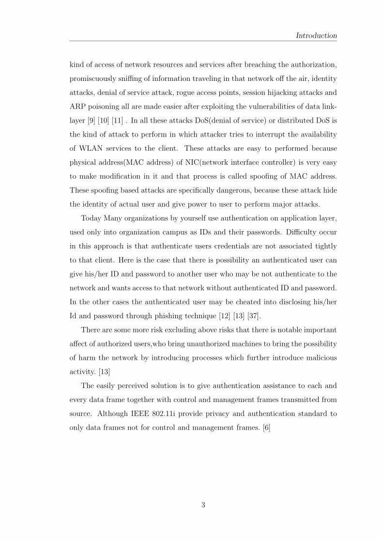
media access control and for the layer below MAC, PHY-physical layer that is
used for communication up to the LLC layer, as figure-1.1 shows that [14].
Figure 1.1: 802.11 and OSI Model
1.2.2 WLAN Components
Physical visible architecture of WLAN is somewhat simple and easy to manage.
Primary components required in WLAN are Network Interface Cards (NICs) also
known as client machine adapters and access points (APs) [3].
Access Points
Access Point ( AP ) is actually equal to a wireless LAN hub . It is a device
that allows wireless devices connect to a wired network in a wireless manner also
known as Wi-Fi using given standards. The AP normally connects through wired
network to router as a standalone device, but it can also be an internal part of the
router itself. An Access Point works within a specific provided frequency spectrum
and modulation technique that uses the definite 802.11 standard. Main purpose
and work of access point is tell the clients which are available of its presence and
provide services to that client after authentication and association of that client
to the network provided by that Access Point [3].
5
Page 16
1.2 802.11 WLAN Introduction
Network Interface Cards (NICs)
Wireless client adapter which is known as NIC card in workstation in an infrastruc-
ture mode or in ad-hoc peer to peer mode [15] connected to Access Point(AP) [3]
which provide wireless connectivity to ethernet. PCI- peripheral component in-
terconnect and PCMCIA- Personal Computer Memory Card International Asso-
ciation card is available at the mobile computing devices and also for desktop
machines which connects wirelessly to all the network resources available links.
NIC card of a station machine scans the available channels of different frequencies
provided by wireless access point or another clients for connectivity and associa-
tion to that AP or that client. There is a software driver which enable the NIC in
station machine [3].
MAC Address(Physical Address)
It is also known as physical address of a NIC or a network device. MAC(media
access control) address [16] defined for Network Interface Controller hardware of
a network device. Each workstation or network device has a MAC address for its
NIC card or some other like modems etc. and each and every addresses assigned
to these devices are unique and different. These MAC addresses structure is of
type XX:XX:XX:XX:XX:XX and values are in hexadecimal format expression, it
can contain letters A to F and number 0 to 9. In windows MAC address can be
find out by typing ipconfig /all in cmd and in linux/unix system MAC address
can be find out by typing ifconfig -a in terminal.
Channel Scanning
The main purpose of IEEE 802.11 standard MAC protocol is to scan for available
wireless(WLAN) networks. The wireless workstation searches for present wire-
less networks and after that try to associate with that wireless service resource
provider. According to IEEE 802.11 network standards scanning techniques di-
vided into two types. [13]
1. Passive scanning:- This scanning mode include the process in which the NIC
of a workstation listens for beacon frames at a time only on one channel
6
Page 17
1.2 802.11 WLAN Introduction
transmitted from Access Points(AP). By using that beacon frames it collects
related signal strength of that station and other useful information needed
by that Access Point(AP). After using that information,the NIC chooses the
Access Point for association to that. [13] [17]
2. Active scanning:- In this mode of scanning Probe request frames are trans-
mitted on every available channels. In responses of probe request frame
workstation got Probe response frames from near Access Point(AP) which
are eventually processed and analyzed by the workstation NIC. By default
scanning technique is Active scanning for most of the NIC card, In this scan-
ning no station have to wait for beacon frames transmitted by access points
for connectivity. It provide quick response from an AP. [13] [17]
1.2.3 WLAN Connection Process
IEEE 802.11 standard defined in its standard that each and every stations must
have to maintain two variables which are totally dependent on the Authentication,
De-Authentication process and other one is Association, DisAssociation, ReAsso-
ciation services. Those two variables are
1. Authentication state
2. Association state
Main working of these variables is to find out the order in which some specific
services have to be invoked and the other purpose of these variables is to find
out when a station starts the service of data delivery. A workstation may be si-
multaneously authenticated with many available different stations but at a time
that workstation be associated with only one other station [5]. All the wireless
workstation start in state 1, In this state workstation may use fixed frame types.
This frames are used to find out what 802.11 WLAN, an ESS(Extended Service
Set) [5], and its Access Points are available and which are required to process the
mandatory frame handshake protocols, and to process the authentication service.
Only If a workstation is IBSS(Independent Basic Service Set) [5],have permission
7
Page 18
1.2 802.11 WLAN Introduction
Figure 1.2: Connection Phases
to process data service in state 1 [18]. Probe requests frames announce work-
stations sustainable transmission data rates and 802.11 other capabilities. Here
probe request frame is broadcast from the workstation to BSSID of ff:ff:ff:ff:ff:ff
all Access points(AP) and after that all Access Point who receives probe request
frames it will respond.
All Access Points who received the probe request frame find out that work
station has at least one same sustainable transmission data rates. If they have
well matched transmission data rates, a probe response frame is transmitted, which
advertising wireless network name in terms of SSID, supported transmission data
8
Page 19
1.2 802.11 WLAN Introduction
Figure 1.3: Association Process
rates, required encryption if necessary, and other remaining 802.11 capabilities of
the Access Point. Workstation receives probe responses from all AP and among all
the available network it chooses most compatible network for association. Decision
of selecting most Compatibility would be based on encryption type,data rates etc.
Once most compatible network is decided workstation will try to authenticate
to that APs. Workstation sends a 802.11 authentication frame to an AP from
which it wants to associate and setting the authentication process to open and the
sequence.At Access Point side it receives the authentication frame transmitted
by workstation and responds to tha workstation with authentication frame set to
open indicating a sequence [5] [18].
9
Page 20
1.2 802.11 WLAN Introduction
When process enters into state 2 which shows that workstation decided the
access point and authenticated state has to be achieved in these state and after
achieving this state process moves toward third state. Completion of this state
shows successful authentication. After completion of this state additional frame
like association frames or disassociation frames are transmitted to that access
point to make associate, re-associate, and disassociate services to the network.
Association request frame include chosen compatible required encryption type
and remaining other compatible 802.11 capabilities. If the information in the
association request frame is same as the capabilities of the AP, Association ID
will be created as a result by Access Point for that workstation and after that
respond with an association response frame with a message which shows that
workstation is now allowed to access network [5] [18].
In this last state 3, all frames are allowed and data delivery service is also
allowed. A workstation have to process all the frames it receives in each of the
states, it has to process those frames also which are not allowed in that specific
state. If a workstation receives frames that are not allowed in state 1 and from
other workstation which are not authorized to receiving workstation then it will
send a de-authentication frame for deauthentication notification to other work-
station. In another case if a workstation receives frames which are not allowed
in state 2 from any machine which is authenticated to receiving machine but not
associated to that machine will send a dis-association frame for notify disassocia-
tion state to that other workstation. All these notifications from workstation will
make the situation that other workstation will make a transition to the proper
state for proceeding further [5] [18].
1.2.4 802.11 authentication model
Supplicant - Host device/workstation (STA)
Authenticator - Light weight access point(LAP)/access point (AP)
Authentication server - It is an access point or an dedicated server machine on
which server application is running
Port - It is a state of logical type which is implemented in software in the AP
10
Page 21
1.2 802.11 WLAN Introduction
The supplicant(Host machine) requests for accessing the services provided in other
Figure 1.4: 802.11 authentication model [1]
words wants to connect to the network.
The authenticator(access point) controls the services and decide that which host
machine can access to that services (controls the state of a port).
The authentication server(access point or any other machine) authorizes the host
machine so that it can access to the services.
1. First step include authentication of supplicant(host machine) to the authen-
tication server.
2. If the authentication phase is successful, the authentication server com-
manded the authenticator to switch the port on so that services can be
accessible.
3. The authentication server(AP) tells the supplicant(host machine) that ser-
vice access is allowed [1].
1.2.5 IEEE 802.11 Rate Adaptation
Standards in IEEE 802.11 implementation provide one of the modulation DSSS
(Direct Sequence Spread Spectrum) mainly propose only two data transmission
rates: all the transferral and communication are either through speed of 1Mbps
or 2Mbps transmission rate. In past, the IEEE specify two high transmission rate
expansion:
11
Page 22
1.3 Address Resolution Protocol Introduction
1. 802.11b whose modulation type is DSSS technology of 2.4GHz band, pro-
viding transmission data rates up to 11Mbps.
2. 802.11a, whose modulation type is OFDM(Orthogonal Frequency Division
Multiplexing) technology of 5GHz band, providing transmission data trans-
ferral rates up to speed of 54 Mbps.
The 802.11g standard that expand the capabilities of 802.11b protocol supports
transmission data transferral rates up to speed of 54 Mbps in same band of 2.4
GHz. Wireless Network (802.11 Standard ) is highly changeable and inconsistent
in nature and there are various reasons for these kind of nature of wireless network.
Wireless Network performance will affected mainly due to degradation in quality
of with mainly reason are getting interference form other wireless source, fading
in strength of signal and attenuation etc.
As the signal becomes weaker, changes of modulation mode and data rate to
optimize performance Adaptive Rate Selection (ARS) invoked. In this technique
there will be switch between different higher transmission rates [19].
1.3 Address Resolution Protocol
This protocol’s main working is to solve out the mapping purpose of logical IP
addresses of 32 bit into their corresponding MAC(physical) address of 48 bits.
ARP protocol implementation communicates using four messages.
1. ARP Request message:- This message is used to request for resolving given
logical IP address to its corresponding associated MAC(physical) address.
This ARP-Request frames are broadcasted to every available devices con-
nected to that network.
2. ARP Reply message:- Each workstation which receives this message will
process to that request and check it out that if it is allocated that specific
IP address and if it contained that requested IP address(logical) then it will
inform its MAC address to the requesting workstation.
12
Page 23
1.4 MAC Layer Attacks Introduction
3. Reverse ARP (RARP) Request message:- A RARP Request is reverse pro-
cess of ARP request message. In this message it request for IP address(logical)
of the device whose given MAC address(physical) transmitted into that re-
quest message.
4. Reverse ARP (RARP) Reply message:- It is the response of the RARP
request, which containing the MAC address(physical) of corresponding IP
address(logical).
Once a workstation receives ARP reply message from other workstation it updates
and fill its ARP cache table with the new updated information about association
of IP address to MAC address and vice-versa [20].
1.4 MAC Layer Attacks
In Wireless networks it is very easy for attackers who are within range of that
network to perform various kind of attacks because it is very easy to sniff that
network transmissions. 802.11 standard have many flaws and weakness in its secu-
rity mechanisms due to some vulnerabilities in its MAC protocol design which give
power to attacker to perform various number of possible harmful attacks.There
are two ways to perform attack first is passive and other one is active.
Attacks which are due to flaws in MAC Protocol:-
1.4.1 ARP Poisoning Attack
ARP cache poisoning is a activity in which an attacker workstation sends spoofed(fake)
(ARP) messages onto a Wireless Local Area Network. Idea behind this activity
is to associated IP address of victim(exploited) machine with the MAC address of
attacker’s machine. So that all the traffic which are meant to be passed to that
IP address(victim machine) will now be passed to the attacker machine. ARP
spoofing may allow an attacker to track all data frames on a WLAN, modifica-
tion of the traffic, or instead of modification attacker can stop the traffic too.
Mostly this attack is performed for opening door for other attacks, like as session
13
Page 24
1.4 MAC Layer Attacks Introduction
hijacking attacks, man in the middle(MITM) attack and DoS(denial of service)
attack [20] [21].
1.4.2 Denial of service (DoS) or Distributed Denial of ser-vice (DDoS) attack
Today Denial of service (DoS) or distributed DoS attacks have become a ma-
jor serious threat to wireless networks. Mainly today it is hard for attackers to
overload the victims resources from it’s single machine because of cheap hard-
ware,so all the DoS attacks were launched with the help of different distributed
machines(attacking hosts). These attacks with this technique is called distributed
denial of service (DDoS) attacks. In these attack victim machine get saturated to
communication requests or from accessing to resources and due to that it can not
respond to authorized legal traffic, or if anyhow it will responds to that it is very
slowly as to be seems like not available currently.
To perform this attack attacker may spoof its MAC address with MAC address
of victim machine and then send frame like de-authentication or disassociation
frame to access point which results victim machine also get disconnects to that
wireless network or attacker may spoof its MAC address with the MAC address
of Access Point and send disassociation packets to all the machine connected to
that Access Point and get all the resources to itself [10] [22].
A SYN flood part of DoS attack happens when a attacker sends a flood of
TCP/SYN packets,with a spoofed sender MAC address. All of these packets is like
a request for connection,which causing the server to sending back a TCP/SYN-
ACK(acknowledge) packet for start and maintain a half-open connection, and
after that waiting for a response packet from the sender address but the response
never comes because of spoofed sender address . These all half-open connections
overload the server capabilities of making connections to other workstations, and
due to these half-open connections all legitimate requests goes rejected [22].
14
Page 25
1.5 Security Solutions Basics Introduction
1.4.3 Man-In-The-Middle Attack
MITM-man in the middle attack in wireless network is a kind of eavesdropping
in which the attacker make connections independently with each of the victims
and repeat messages between them, attacker makes them believe that they are
communicate to each other directly as in a connection which work as private after
handshake,but the true fact is that all the complete communication is watched and
controlled by that attacker. In this attack attacker is possibly be able to snatches
and checks all messages which are going between that two victims and attacker can
also create new messages and inject them into between there communications.A
man in middle attack only be possible when attacker succeed in pretend to be
second victim for first one and first victim for second one. In the short each hosts
be satisfactory to the other host.
In this attack attacker first find out the victim’s IP addresses and then perform
arpspoof to victim 1 with the IP address of victim 2 and with own MAC address
and together with that process perform same process with victim 2 that send spoof
arp messages to victim 2 by faking itself as victim 1. Then all the traffic will be
pass through that attacker machine and to grab some credentials there are various
tools like dsniff [23] [24].
1.5 Security Solutions Basics
1.5.1 802.11 Management frames FingerPrinting
The implementations of 802.11 standards describe broadly various types of frames
used by NICs of workstations and access points for communications to each other,
and they are also used for controlling and managing the wireless network. Every
frame used by wireless network has a control field that describe the IEEE 802.11
frame type, protocol version, and various other useful informations like as power
management is active or not, whether WAP/WAP2 is used and so on. In all of
these frames there is one information which is always present and that information
is MAC addresses of the both destination and source workstation either it may
be client machine or access point, for error detection- frame check sequence,frame
15
Page 26
1.5 Security Solutions Basics Introduction
sequence number etc.
802.11 management frames are the frames type which are used to enable work-
stations and access point to create and maintain communications between sta-
tions.All IEEE 802.11 management frames have a 24 Bytes standard header.
They contain: Frame control,Duration/ID,Destination address(DA),Source ad-
dress(SA),BSSID,Sequence control,Frame Check Sequence(FCS). The following
are common 802.11 management frame subtypes used [25]
� Beacon Frame
� Probe Requets Frame
� Probe-Response Frame
� Authentication Request frame
� Authentication Response
� Association Request frame
� Association Response frame
� Disassociation frame
� Deauthentication frame
� Reassociation Request frame
� Reassociation Response frame
� Information Elements and Fields
� Management Frame Fields
� Management Frame Information Elements
FingerPrinting :- FingerPrinting is the Process of collecting information from
the specific workstation to make its profile in order to the identify this workstation
in future by comparing its profile to current nature of workstation. This fingerprint
16
Page 27
1.5 Security Solutions Basics Introduction
should be like the fingerprint in human because human fingerprints are unique and
different individually and can’t be spoofed. Through this process all the informa-
tion about workstation, NIC drivers,software and different drivers workstation is
using can be find out uniquely as they are observable characteristics.
In this technique a profile is created of workstation through analysis of timing
behavior of different 802.11 management frames. Unique timing profile is created
because that timing profile is used to find out the actual device by comparing the
stored profile to current captured profile [26]. FingerPrinting can be done in two
ways
1. Passive: It uses a sniffer to capture traffic sent from a system. It analyzes
that traffic to find out what the system implementation is. A key point is
that passive technique does not send any traffic to the target system but
instead just collects the traffic and analyzes it. This technique also refers
as noninvasive technique because it does not require co-operation from the
system of which fingerprinting is performing [13].
2. Active: It discovers related informations about the firmware, the chipset
or the driver of an 802.11 standard wireless device by observing and an-
alyzing its responses to a series of crafted, non-standardized malformed
802.11 frames. It is also known as invasive technique because it requires
co-operation from the system because this technique depend upon the reply
it gets from the system on which fingerprinting is performing [13].
1.5.2 Sequence Numbers
There is a field known as sequence number field present in the 802.11 standard
MAC frame header. Each and every frame transmitted from hosts device has a
unique sequence number associated with it, host device increments the sequence
number every time it transmit a frame. This sequence number field is needed
because of re-assembling of fragments at destination hosts device. Re-assemble is
needed because of fragments are transmitted in different order so ta reorder all
the fragments that sequence number is needed. According to the defined 802.11
17
Page 28
1.5 Security Solutions Basics Introduction
standard sequence number field value of each and every frame is assigned by
a defined counter variable, value of this counter variable is incremented by one
whenever a frame is transmitted and value of sequence number field is always
modulo 4096 [6].
According to IEEE 802.11 standards every device which are connected to that
network and communicating and during communication each and every manage-
ment frame and data frame contains the 12-bit sequence number field in its 802.11
MAC header, which is incremented by one every time. Control frames types trans-
mission do not get a sequence number field in their frames [4]. If a workstation is
seems as another workstation means one workstation using the identity of another,
then this condition(kind an attack) will generate two different chain of values of
sequence numbers field which can be detected easily.
There is a wayout by which refined attacker could hide his steps would be have
latest values of sequence number of current actual device recently transmitted
MAC frame, so that attacker can send its frame by same frame number and by
turn that frame into retransmission of that frame by flipping the retransmission
bit the 802.11 header and making all this situation as natural retransmission.
In another way attacker would include hijacking the complete sequence by
corrupting the actual legal frame by victim machine and instead of that sending
out a frame with the next successive sequence number and corrupted frames got
drop by the other machine. In this technique there is a weakness that even if
sequence number analysis effectively be done there is always a possibilities that
refined attacker can easily hide its tracks with respect to the sequence numbers [4].
1.5.3 Signal Strength
This technique may be either passive or active. In this fingerprinting approach,
the location of each and every host machine measured by the received signal
strength (RSS) of host-transmitted frames and packets with related to n number
of installed access points(AP) within that range of that access point. The resultant
signal strength(RSSI) in combination of n-tuple represent the signalprint [27] [28]
of each host machine at that some location. To handle the situation when there
18
Page 29
1.6 Intrusion Detection Systems Introduction
will nonstationary hosts are present, the signalprint(fingerprint) of each wireless
host is constantly tracked and updated. That RSS-Received signal strength [27]
information, which has been used for Identity Based Attacks detection technique
because of its property of location distinction and availability of this feature in the
network interface controller (NIC) card in the present off-the-shelf devices. signal
strength profiles, which are created as a fingerprint profiles are location specific
and that can be used as Identity Based Attacks detection in environments which
are static type. In this technique, the receiver machine asks the sender machine
(associated with an identity) to report the RSS records and create profiles at the
time of their past communication captured. If at some time there is no Identity
Based Attacks, the announced RSS(signal strength) variation should be related
with the receiver’s machine observation. In any case if there is an Identity Based
Attacks, the RSS(signal strength) records and profiles observed and analyzed by
a exploited node should be a mixture of the RSS produced by the genuine client
machine and the attacker machine. Since the attacker machine cannot figure it out
that the RSS(signal strength) variations analyzed by the genuine user machine,
its reported records and profiles should be less correlated with the victim node’s
machine, and the attack can be detected [27] [28].
1.6 Intrusion Detection Systems
Intrusion detection System(IDS) [29] [7] [9] can be elaborate as detection system
which is of type automated and which is used to alert the available system and
security systems by generating an alarm at a location where that attack is taken
place. If any attack or intrusions have taken place or something different from
natural activity happened IDS come into existence and actions have been taken.
An Intrusion Detection system (IDS) is a system used for detection and also as
for defensive purpose from network attacks by detecting hostile activities/differ-
ent from daily activity in a network and then tries to possibly detects and stop
such activities that may exploit and compromise the system or network security.
IDS attain detection by continuously monitoring and analyzing the network for
19
Page 30
1.7 Summary Introduction
abnormal activity, some special attacks and activity which are different from daily
activity. The prevention part of Intrusion detection and prevention system may
involve issuing alerts and generation of alarms as well as taking actions like as di-
rect prevention measures such as blocking a real or suspected host or untrustable
connection. In different definition, intrusion detection system is a technique and
process which identifying unusual activity and after that make response to that
abnormal and malicious activity targeted at computing and networking resources.
Apart from these functionality IDS are capable of differentiate between attacks
which are generated from inside(insider attacks) the network and external ones
generated from outside.
1.7 Summary
Throughout this chapter, what ever is discussed is just to create a basic under-
standing for this research work. It begins with knowledge basically required like
the 802.11 standard, Wireless Network basics, connectivity phases and identity
based attacks on 802.11 networks. Basics related to Intrusion Detection Systems
and techniques is also discussed. This all basics are very helpful in our proposed
technique and also in implementing our technique.
For some more basics information is there are sources available majorly like
802.11 wireless networks MAC layer working and Physical layer working [5] [4].
Intrusion Detection System can be more find out in research paper wired and
wireless intrusion detection system :classifications, good characteristics and state
of art [8] [7]. Information about identity based attacks on wireless network is on
security issues in wireless network [9] [20] [22].
1.8 Thesis Organization
The rest of the thesis is organized as follows.
In Chapter-2 will provide a overview of the related work and research done
till now on detection of identity(spoofed) based attack. Which will lighten you up
with a little deep knowledge about spoof attacks and their detection techniques
20
Page 31
1.8 Thesis Organization Introduction
and help you to understand the needs, the drawbacks and various way to detection
of spoofed(identity) based attacks.
In Chapter-3 will take you through our proposed technique of spoofed wireless
device detection with management frames with some basic theoretical knowledge
about the technology used and the simulation and results of our proposed work.
In Chapter-4 the overall work with drawbacks is expressed in the section
Conclusion and the possible future work is described in the Future Work section.
21
Page 32
Literature Review
Page 33
Chapter 2
Literature Review
Detecting Identity Based Attacks in Wireless Networks Using Signal-
prints
In this paper they create a profile called signalprinting type of fingerprint using
signal strength reported by access points which are further used for find out what
are reliable authorized client stations and other misbehaving unauthorized device.
Signalprints are tightly related to current physical location of clients workstation.
In this technique any interested packet like as authentication/deauthentication
request is transmitted over the wireless network, and then it is captured by access
points within that range, that packet include information about signal strength
measurements as RSSI levels and passed that information to the centralized server.
That information is then stored for future comparison as a signalprint profile, this
profile is a tuple created by collecting all measurements reported by all the access
points. All signalprint is characterized as a vector in which there will be one entry
for each access point captured signal strength measurements. There are different
transmitters are installed at different locations which generate different signal-
prints because signal strength changed either increase or decrease with decreasing
or increasing in distance, which helps the monitor system to correctly differentiate
clients workstations located at different locations.
One limitation of this technique is that it may not able to differentiate between
two devices which are located physically nearby to each other. Masquerading
attacks can be detected only if there is difference in signal strength (RSSI) is
23
Page 34
Literature Review
notable with respect to at least one or more access point.
This technique may also not be capable to detect DoS attacks which are com-
posed of only less packets for example single-packet deauthentication attack which
de authenticates the victim machine from that network may go unnoticeable. This
attack only be detectable if there are more enough packets involved so that there
will be more signalprints for processing and comparison [27].
Identifying Unique Devices through Wireless Fingerprinting
In this paper they propose a wireless device fingerprinting technique in which
there will be a profile which is created of different devices using probe request
frames timing behaviour.They developed a completely passive technique. Here
passive means the process which did not require assistance and help from the fin-
gerprintee machine. Their technique is depend on the probe request frames timing
behaviour and its analysis. This process is done by creating the fixed size time
interval bins so that all the frames are divided into that timing bins according to
their timing information for all the known workstations into that network and that
complete information of timing bins is called signature(fingerprint) of machines.
Signature is created for each and every machine existed in that network and stored
in database for future use.
One of the advantages of this technique is that it doesn’t required coopera-
tion from other machine and through this technique they find out uniform minute
differences in probe request’s timing intervals transmitted from different worksta-
tions, even when they used same NIC drivers.
The first limitation in this technique that the two devices which are actually
same, sometimes due to traffic in network shows different behaviour and thats the
reason its not easy to infer that two devices are same. Sometimes in the other case
due to limited samples some different devices also seems like they are the same
device because of similar limited samples.
The second limitation is the data and time required to fingerprint each device
in that network. As this fingerprinting technique concentrate only on analyzing
24
Page 35
Literature Review
the inter-burst latencies and due to that it will take around at least an hour , so
that profile of signature can be used for finding out which devices are authorized
and which are not [26].
On Physical-Layer Identification of Wireless Devices
In this work, they focus and develop techniques using physical layer properties and
thats why this technique is called physical layer identification. In this technique
wireless devices are identified characteristics of their analog circuitry which are
unique and different from others. In this process physical-layer device identifica-
tion [30] is done by taking and analyzing properties of analog circuitry of a device
during communications between devices and develop a fingerprinting [26] using
properties of physical layer. This process identification of device using properties
of physical-layer is possible due to imperfections in hardware analog circuitry dur-
ing manufacturing process. Results of these imperfections and defects introduced
in hardware analog circuitry shows in the transmitted signal which makes them
correctly measurable. Even if there will be more precise and correct manufactur-
ing and quality control is very good there is possibilities that these manufacturing
imperfections could minimized but in practical it is hard to achieve because of
high rate productions .
In their process two modules are used for identification of system: enrollment
and other one is identification. In enrollment module, signals are captured when
devices are communicating from each and every device. These signals are stored
as informative manner and called fingerprints of each device stored in database.
All devices fingerprint linked with some unique ID representing the corresponding
device. In identification module,devices which are communicating in that network
are identified using stored reference fingerprints obtained in enrollment module.
They use different Physically Unclonable Functions(PUF) [31] [30] for identifi-
cation of device using physical properties of that device. Devices which contain
PUF-enabled RFID processors contain a circuit which represents input challenges
to output responses using a function (PUF)and which is discovered by the internal
25
Page 36
Literature Review
characteristic and variations of that circuit [30].
Passive Data Link Layer 802.11 Wireless Device Driver Fingerprinting
The researcher proposed technique in this paper is completely passive, means no
need of getting reply from the victim machine. They choose passive fingerprinting
techniques [26] because these techniques have advantages over active techniques
interms of transmitting data that passive approaches do not transmit data.Their
proposed fingerprinting approach takes advantages of implementations differences
to fingerprinting a device because algorithm used for scanning access points is
not defined properly and universally in the 802.11 standard. So lack of stan-
dard specification of a probing algorithm make wireless device drivers different
from each other. Particularly, their approach is focused around statistical analy-
sis of the timing differences(inter-frame) between transmitted probe requests [25].
This timing-based(inter-frame) technique has a many benefits over a content-based
technique. There fingerprinting approach moves in two modules: first one is cap-
turing traces and second one is generation of fingerprinting. In first module probe
request are capture for fingerprinting of that device. In the second phase probe
request behaviour is characterized using that captured data. They chooses binning
technique to implement their proposed technique. By using binning approach they
characterizes probe requests delta time. Binning approach works by converting an
continuous data points(frame timing interval) into discrete size bins. A time bin
is an integral time value used for dividing continuous data in discrete. They use
equal-width binning means where size of each bin is same. They calculating bin
probabilities and bin mean as device signature(fingerprint). These signature are
used in future during verification of device. There will be calculating of closeness
between stored signature and current collection of device traces.
Drawbacks of their fingerprinting technique is when a new driver version came
that version is patched with previous vulnerabilities in driver. Due to that device
fingerprint works differently and stored fingerprint work differently [32].
26
Page 37
Literature Review
A Passive Approach to Wireless Device Fingerprinting
In this research they provide a wireless device fingerprinting passive approach that
utilizes a blackbox-based [33] process. This approach can be used for defensive
or offensive purposes and is extensile to any wireless network device. Blackbox
testing process is a popular approach which is used to testing the software where
the contents used are obscure to the tester. To lead the test, a stimulant is given
as input of the software and after that output is analyzed. In this process tester
can figure out the result that how the software will respond to the input. In this
research blackbox is Access Point instead of software and just same as testers of
software are not stick and serious to source code of software, researches in this
process not considered the proprietary structure of the Access Point. The packet
train is given as input to blackbox which is a access point and after that output
which is also packet train is analyzed, although there will be shifting in time of
that individual packets in that packet train. That shifting of time is a output
of the internal structure of the access point(AP). Because each and every access
point(AP) has a structure which distinguish itself from others, and this shifting
of time is different for each access point which make it unique for access point.
Researchers used wavelet analysis [34] to extract the unique and different patterns
which are as a result from internal structure [35].
One limitation of their research work was that the results were for based on
very few access point tested. They conduct their experiments using a wireless test
set with imitate network traffic as instead of real traffic [35].
27
Page 38
Literature Review
Detection of Masqueraded Wireless Access Using 802.11 MAC Layer
Fingerprints
This paper acknowledges the situation where the spoofer(attacker) holds up till the
authorized client has completed the its session, and afterward of session completion
attacker exploits that whitelisted MAC address for the network access [2]. They
create a technique focused around analysis statistically of the timing difference
between transmitted probe request [25] as interframe timing of probe requests
with a specific end goal to recognize a particular wireless driver, and the conclusion
is that the dominant part of wireless drivers do have a different fingerprint [26].
There are various differences in implementations of the Null Data frames that
can be used for making differences in different NIC drivers. They used seven
rules [36] to recognize diverse behaviour with respect to the Null Data frames. The
main center of focus in this research is on the attack type MAC spoofing where
the exploited machine and attacker don’t have to be connected all the while.
MAC layer [2] behaviour differs from station to station in various perspectives
because of implementations and usage differences of the 802.11 protocol.These
differences found out in properties and standards is called fingerprinting properties,
and base for making differences are Null Data frame behavior [36].they used various
distinctive featrues for making diffeences between various devices. Features are
like PS-Poll, Keep Alive, Null before Probe, Null Data Type, Listen Interval,
Association Request Duration, Fixed Interval etc.
Advantage of this technique is that this are capable to find out spoofing attacks
where the attacker and exploited user is not connected simultaneously. Precom-
puted stored database of fingerprints is not required [37] .
Sequence Number-Based MAC Address Spoof Detection
In This paper they proposes a technique related to link-layer in which sequence
number field of MAC header is used.During communication each host transmit
MAC frame with a unique sequence number [2] [4], which the every hosts device
28
Page 39
2.1 Summary Literature Review
increments by one every time it transmits a frame. The main purpose of sequence
number is to re-assemble and re-organize fragments of a MAC frame at destination
hosts device same as source hosts device. According to their proposed technique
monitor system keeps track of each wireless device latest sequence number so that
if some attacker try to imitate a hosts device it will need to spoof the MAC source
address of that hosts device as well as its related sequence number used during
that communication. There are two cases which monitor system covers :-
1. In the first case if captured spoofed frame’s sequence number is smaller or
equal to current sequence number of that transmitting actual hosts device
than that spoofed frame is observed as a retransmitted frame and thus if it
is retransmitted frame than that frame’s content have to be same as the last
frame with the equal sequence number. So in the first case spoofed frame
can not do any damage to system because its just a replica to the previous
frame same sequence number.
2. In second case if captured spoofed frame’s sequence number is larger than
the current sequence number of that transmitting actual hosts device, than
there is spoofed message whose content is different and may be harmful to
the system. This attack cannot be detected soon. This attack can only be
exposed if later when actual device transmit its frame with that spoofed
frame sequence number and content of its frame is not as same as spoofed
message [6].
one weakness figured out in this technique which is most principal that it requires
the exploited person machine and attacker machine ought to be in the same net-
work, so that by utilizing ARP request and ARP response to upgrade most latest
exploited person sequence number.
2.1 Summary
These are the some of the related I have studied on spoofed device attack iden-
tification techniques. Through this literature review all the techniques till now
29
Page 40
2.1 Summary Literature Review
either works on only probe request, signal strength or sequence number field and
latest technique is using 802.11 MAC layer implementation properties, which is
used to distinguish one device from other. In the case of sequence number de-
tection technique, compulsory and most needed thing is both victim and attacker
together will be present in the network only that time attack will be detected. I
found the spoofing detection is more tough when both victim and attacker both
are not present simultaneously.
30
Page 41
Proposed Techniqueand Simulation
Introduction
Our Proposed Technique
Implementation
Summary
Page 42
Chapter 3
Proposed Technique andSimulation
3.1 Introduction
The real motivation behind this proposed work is that today there are several vul-
nerabilities and weakness in implementations of 802.11 MAC layer standards [5].
Attacks of type MAC spoofing are a remarkable serious threat to 802.11 wireless
networks because it is very easy to theft identity of authorized clients in that
network and perform other serious attack without showing their actual identity.
This proposed algorithm is developed to fingerprint the device using MAC layer
properties to find out that spoofing attacks where victim machine and attacker
machine not connected together to the network. Fingerprint is created on the basis
of different behavior shown by device of which fingerprint is created and each de-
vice behavior is unique because there are differences available in implementations
of 802.11 protocol. The proposed technique have some part active and some part
passive in nature, means it creates fingerprint of the device by using both active
and passive technique [37]. Passive technique give positive and strong detection
in compare to active technique because this active technique provide stronger de-
tection only if gets reply from the other target system. But active technique is
much more faster than passive ones and detects after few frames exchanged.
32
Page 43
3.2 Our Proposed Technique Proposed Technique and Simulation
3.2 Our Proposed Technique
3.2.1 Spoofed Wireless Device Detection using Manage-ment Frames Fingerprinting
802.11 standards are diverse in implementations which differ the behavior of each
device from other devices [5]. These differences are the main property which make
possible for developing fingerprinting using management and control frames of
MAC layer and other properties. There is the fact that the approach used in
channel scanning for finding out the available nearest access points is not defined
in standard manner in 802.11 protocol standards [32] [35]. Due to this fact all
manufacturers have implement algorithms and approach in there way which are
different from others. By taking all these properties together and creating a profile
which is unique for each device and that profile is used for identification of device
in future. This whole process is called Wireless Device Driver Fingerprinting and
majority of wireless device drivers do have a distinct and unique fingerprint [37].
There is already an available approach [13] [32] which is based on inter-frame
timing (timing difference between probe requests) and for fingerprinting statistical
analysis is used so that in future that analysis can be used for identifications of
that fingerprint device [26] [30] .
Our main approach is based on timing signal behavior which provide diversities
in the NIC card [37]. To detect these MAC spoofing attack, our approach mainly
focus on timing differences between different frames transmitted by NIC card
during communication setup phases [38] [4].
There are various challenges faced during implementation of our proposed de-
vice fingerprint approach.
1. In the MAC protocol standards there are various properties and parameters
which are associated to MAC frame and combinations of that properties and
parameters are distinct for a device. Choosing that parameters is one of the
biggest challenge.
2. Upgradation of device firmware can change its possible normal last version
of device behavior.
33
Page 44
3.2 Our Proposed Technique Proposed Technique and Simulation
3. Last challenge is like devices from same vendors or different vendors which
may have same implementations of MAC protocol standards.
3.2.2 Basics Behind Proposed Technique
This section will give basic knowledge on the 802.11 MAC protocol standard,
802.11 MAC frames [5] used in network. These frames are used for fingerprinting
the device.
Functionality of MAC Layer
1. Providing data delivery in reliable way
2. Good Control access to the shared wireless medium.
3. Data delivers in protective way [5].
MAC Layer Packet Structure
The basic MAC(Medium Access Control) [5] layer packet format [2] which is passed
to PHY(Physical) layer from the MAC layer is shown in figure. Some of the fields
of this basic frame format is not contained by all the packets. But in data packets
all of these fields are present. Four addresses field are present in frame format
and all of these needed because sometimes users are connected to different access
points and due to that MAC address of access point is also required. So addresses
of both the access points and addresses of both the clients are present in these
four address fields [39].
Figure 3.1: MAC Layer Packet Structure [2]
34
Page 45
3.2 Our Proposed Technique Proposed Technique and Simulation
Management Frames The main purpose and use of management frames are
to create and maintain the wireless network between the station machine and
access point. The usage of management frames is not just important for creating
link between devices but also they are useful in maintaining the network link in for
confirming that the station machine are still present there, but with considering
this there are other network link also present with some good related parameters
to get a best connectivity. These frames have many different subtypes [40].
Table 3.1: 802.11 Management Frames [4]
Type Description Subtype value Subtype DescriptionManagement 0000 Association requestManagement 0001 Association responseManagement 0010 Reassociation requestManagement 0011 Reassociation responseManagement 0100 Probe requestManagement 0101 Probe responseManagement 0110 Timing AdvertisementManagement 0111 ReservedManagement 1000 BeaconManagement 1001 ATIMManagement 1010 DisassociationManagement 1011 AuthenticationManagement 1100 DeauthenticationManagement 1101 ActionManagement 1110 Action No AckManagement 1111 Reserved
Control Frames The main purpose of these control frames are in the supporting
in data frames delivery. These frames purpose is to avoid collision between frames
due to hidden station problem connectivity. The other purpose is to acknowledge
frames during transmission of frames are correctly. Sequence control field which
is available in default MAC frame format is not present in control frames [40].
35
Page 46
3.2 Our Proposed Technique Proposed Technique and Simulation
Table 3.2: 802.11 Control Frames [4]
Type Description Subtype value Subtype DescriptionControl 00000110 ReservedControl 0111 Control WrapperControl 1000 Block Ack Request (BlockAckReq)Control 1001 Block Ack (BlockAck)Control 1010 PS-PollControl 1011 RTSControl 1100 CTSControl 1101 ACKControl 1110 CF-EndControl 1111 CF-End + CF-Ack
Null Data Frames Behavior These frames are important and special type
of used frames in 802.11 wireless network. They are special data frames in which
frame body field is empty in MAC frame format and these are the only frame
which are not defined universally in the 802.11 standards [5]. But in actual NIC
implementation these frames are used in variety of features used by NIC card
like scanning of channel, association keep alive, PS-Power save management etc.
There are seven rules defined in “Null Data Frame: A Double-Edged Sword in
IEEE 802.11 WLANs” [36] which is used for identification of different behavior
shown by these frames [37].
3.2.3 Proposed Technique
In our proposed approach available features of 802.11 standard implementation
[5] which make distinguishable each device from other device are used, and this
complete collection of this information is called fingerprinting properties.
The whole proposed approach is divided into three types of information first is
based on Probe request details, second is authentication request details, and third
one is association request details.
36
Page 47
3.2 Our Proposed Technique Proposed Technique and Simulation
The whole process working is divided into 3 phases
1. Packet capture and Information extraction
2. Creation of Fingerprint signature
3. Measurement of Similarity
First Phase
In this phase probe requests frames, authentication request frames,and association
request frames and other management frames are captured and from those frames
information are extracted like inter arrival time,delta time between frames,power
constraint,supported rates etc. These information are features of NIC card which
makes it distinguishable from others device NIC card [4].
Table 3.3: Management frames usable fields
Property ValuesArrival time Arrival time of FrameEpoch time time relative to epoch
Time delta from previous frame Time difference between two consecutive frameTime from first frame Relative time from first frame
Timestamp Time synchronizationType/Subtype different type and subtype of management frames
Sequence number Sequence number field mod 4096 in each frame
Second Phase
After the process of frames capturing and extraction of information from selected
three frames- probe request, authentication request, and association request trans-
mitted by network device of which want to make fingerprint as a signature of that
device. Second phase is generation of fingerprint. In this phase selected main
information are used which distinguish the device from others. So for generating
fingerprint Autocorrelation function is used. In this phase all the three related
frames informations are passed to autocorrelation function [44] [45] and generated
result is used as a fingerprint of that device and stored in the database. That
stored fingerprint later used for identification.
37
Page 48
3.3 Implementation Proposed Technique and Simulation
Third phase
In the third phase measurement is done and find out the most similar signature
from the database to find out the actual device.
3.3 Implementation
3.3.1 Experimental Setup
In this section all necessary setup are discussed. All software,specific NIC con-
figurations, hardware for capturing and processing informations which is required
in this approach. Some of the NIC properties and configurations makes process
harder for collecting all the required informations. All the collected informations
should be in such a manner which should be processable.
3.3.2 Required Equipment
In this experiment all the main machines and hardware used are :-
1. DAP-1155 Wireless N150 Access Point -Access Point
2. HP laptop(Pavilion dv6-3053tx) with kali linux operating system and atheros
model ar9285 802.11 b/g/n wifi adapter - monitor system
3. HP laptop(Pavilion G6-2309TU) with windows 8 operating system and atheros
model ar9485 802.11 b/g/n wifi adapter - host machine
4. Dell Laptop (Inspiron 15 3521) with ubuntu operating system and DW1520
Wireless-N WLAN Half-Mini Card - host machine
3.3.3 Required Software
1. Wireshark (version 1.8.14):- This software is a open source network analyzer
and packet sniffer. This tool can put the NIC(Network interfcae controller)
into promiscuous mode(only supportable) so that it can see all flowing traffic
in that network on that selected interface. Output file produced by this tool
is in pcap format. Tshark is the terminal based mode of wireshark and this
38
Page 49
3.3 Implementation Proposed Technique and Simulation
terminal mode is used to convert pcap file into csv(comma seperated value)
file which is used for processing [41].
2. Airmon-ng (version 1.1):- Airmon-ng is the part of Aircrack-ng network
software suite which include analysis tool,packet sniffer, wireless security
(WEP/WPA/WPA2) cracker. Airmon-ng is a script which is used for putting
NIC into monitor mode on selected interfaces and for again putting that NIC
into normal managed mode [42].
3. Matlab (version R2012a):- This software provide environment interactive in
nature and used for computation of numerical data, data visualization, high
level programming. It provide functionality of graph plotting derived from
data and functions, manipulations in matrix, different algorithms implemen-
tations [43].
3.3.4 Complete Detailed Process
First Phase :- Capturing Packets
This process is done by first put the NIC card of monitor system into monitor mode
using airmon-ng [42] tool. After that wireshark [41] start capturing packets on that
monitor interface. If the packet capturing in an environment where various other
network are also present than after capturing the packet filtering is done according
to device of which fingerprinting is created. That pcap file is converted into csv
file using tshark terminal mode of wireshark. Commands which are used on kali
linux terminal for changing managed mode to monitor mode is given below
1. ifconfig - used to find out the interface used by wireless card
2. iwconfig - find out the card working mode
3. ifconfig wlan0 down - down interface wlan0
4. airmon-ng start wlan0 - create an interface whose working is in monitor
mode. That interface is a sub-interface of wlan0
5. ifconfig wlan0 up - up interface wlan0
39
Page 50
3.3 Implementation Proposed Technique and Simulation
After capturing packets of type probe request,authentication request and associ-
ation request and other management frames(Informative elements) in pcap file.
Filtering is perfomed and useful information is collected using tshark and that is
used to convert that pcap file into csv(comma separated values) file.
1. tshark -r capturedfile.cap -T fields -e frame.number - e frame.time -e
frame.time relative -e frame.time epoch -e netmon 802 11.timestamp -e
wlan.sa -e wlan.seq >capturedfile.csv
Second Phase:- FingerPrint Generation Process
Timing intervals of Probe request,Authentication request, Authentication request
for any specific device have periodical and nearly same assumable each time traffic
is captured. Past experiments shown that probe requests intervals are different
for every NIC [13] [32]. In this phase information collected about probe request,
authentication request and association request for fingerprinting the device has
been presented as signal s(t) in terms of timing, where s is event discrete in nature
that happens in time t. Analysis and fingerprint is generated based on timing
property of all these three packets and together with this process a profile is
created of device using informative element shown in table-3.3 [37] [4].
First of all mean and variance is calculated for timing differences for each of
probe request and relative time from last frame for authentication request frame
and association request frame. After that autocorrelation function is used. This
function is used for finding periodic patterns in the signal etc. Dataset of n data
values {D1,D2. . .Dn} of which mean µ and variance σ2 is known then autocorre-
lation function [44] [45] is defined as
A(k) =1
n ∗ σ2
n−k∑t=1
(Dt − µ)(Dt+k − µ) (3.1)
where k < n
After calculating the autocorrelation of signal to itself discrete fourier trans-
form(DFT) [46] is applied to that for generating the signal.
Yl(f) =l−1∑n=0
Al[n]e−2πkn/N , kεZ (3.2)
40
Page 51
3.3 Implementation Proposed Technique and Simulation
autocorrelation function is also used to find out the similarity between observa-
tions as a function of the time lag between them. If correlated function applied to
signal to itself then that function is called autocorrelation function.
Third Phase- FingerPrint Comparison
In this phase device identification is performed with the help of cross correlation.
Cross correlation technique is used to analysis and find out the similarity between
between two signals, one is the stored database signal(fingerprint) and another
one is captured during the time of identification of device. This functions find
out the correlations between signals in terms of similarity or tell about the offset
between two signal. Result obtained after applied the cross correlation provide
a offset value, which tells that device is actual device or device with faked MAC
address.The cross-correlation [47] function onto the frequency domain obtained
from fourier transform [46] is called the cross spectrum or cross energy density
spectrum. Cross correlation for frequency domain can be calculated as
Φ = FT [Y ∗(f)Z(f)] (3.3)
corr = ifft(conjugate(fft(Y (f))) ∗ fft(Z(f))) (3.4)
where fft=fast fourier transform
ifft= inverse fast fourier transform
Y(f)=Stored signal
Z(f)=captured signal during identification
41
Page 52
3.3 Implementation Proposed Technique and Simulation
we have applied all these three phases used for identification of device. All
these three phases experimented on 4 machines and one monitor machine. From
those 2 machines one have atheros ar9485 NIC card and other one have dw1520
wireless Wlan half-mini NIC card. By using properties of MAC layer and after
analysis of those properties and decision is made that either device is actual one
or not the actual device as it is behaving and registered as some one else.
3.3.5 Results
In this section results will be shown of our proposed technique of different machine
and discussed about them.
Figure 3.2: Probe request timing estimation for atheros ar 9485 NIC card
Figure-3.2 and Figure-3.3 is the result of probe request frames transmitted
by atheros ar-9485 card (hp machine) and DW1520 Wireless-N WLAN Half-Mini
card (Dell machine). This is generated by processing timing details of each frames
transmitted by both of the machine and then resul is converted that time sig-
nal into frequency signal which tells the power trasnmitted by that signal on
corresponding device. This signal is generated by after applying autocorrelation
function [44] [45] to that signal itself.
42
Page 53
3.3 Implementation Proposed Technique and Simulation
Figure 3.3: Probe request timing estimation for DW1520 Half-Mini card NIC card
Figure-3.4 and Figure-3.5 is the result of Authentication request frames trans-
mitted by atheros ar-9485 card (hp machine) and DW1520 Wireless-N WLAN
Half-Mini card (Dell machine). This frame is transmitted by probe response from
the access point and according to this information, relative time difference between
them is used as a processing element.
Figure 3.4: Authentication Request relative time estimation after each probe re-sponse for atheros ar-9485
43
Page 54
3.3 Implementation Proposed Technique and Simulation
Figure 3.5: Authentication Request relative time estimation after each probe re-sponse for DW1520 Half-Mini card
Figure-3.6 and Figure-3.7 is the result of Association request frames transmit-
ted by atheros ar-9485 card (hp machine) and DW1520 Wireless-N WLAN Half-
Mini card (Dell machine). This frame is transmitted by authentication response
from the access point and according to this information, relative time difference
between them is used as a processing element.
Figure 3.6: Association Request relative time estimation after each authenticationresponse for atheros ar-9485
44
Page 55
3.3 Implementation Proposed Technique and Simulation
Figure 3.7: Association Request relative time estimation after each authenticationresponse for DW1520 Half-Mini card
Figure-3.8 is the result of differences between probe request pattern transmit-
ted by atheros ar-9485 card (hp machine) and DW1520 Wireless-N WLAN Half-
Mini card (Dell machine). Cross correlation measures of similarity of two signals
as a function of a time-lag applied to one of them. This graph tells that lag by
around 7 seconds and correlation value is 0.65 which is more than 0.4 confirms
that there is difference between them.
Figure-3.9 is the result of differences between authentication request pattern
transmitted by atheros ar-9485 card (hp machine) and DW1520 Wireless-N WLAN
Half-Mini card (Dell machine) in response of probe response from access point.
This graph tells that lag by around 3 seconds and correlation value is 0.45 which
is more than 0.4 confirms that there is difference between them.
Figure-3.10 is the result of differences between association request pattern
transmitted by atheros ar-9485 card (hp machine) and DW1520 Wireless-N WLAN
Half-Mini card (Dell machine) in response of successful authentication response
from access point. This graph tells that lag by around 7 seconds and correlation
value is 0.41 which is more than 0.4 confirms that there is difference between them.
45
Page 56
3.3 Implementation Proposed Technique and Simulation
Figure 3.8: Cross correlation estimation for probe request between atheros NICand DW1520 Half-Mini card
Figure 3.9: Cross correlation estimation for Authentication request signal betweenatheros NIC and DW1520 Half-Mini card
46
Page 57
3.4 Summary Proposed Technique and Simulation
Figure 3.10: Cross correlation estimation for Association request signal betweenatheros NIC and DW1520 Half-Mini card
3.4 Summary
This chapter covers all my proposed work, implementations and obtained results.
In the results which tells about the differences between devices which have taken
for experiments.
47
Page 58
Conclusion and Future Scope
Conclusion
Future Scope
Page 59
Chapter 4
Conclusion And Future Scope
4.1 Conclusion
In proposed research it is experimented and identification is done with stored fin-
gerprint and captured fingerprint during identification of device. This technique
is able to identify and find out which device is without spoofed MAC address and
actual device and which one is spoofed one in the condition where the both vic-
tim(exploited)device and attacker device need not to be simultaneously connected
. Here this experiment is performed with various machines and it is resulted that
our proposed technique is mostly identify the device correctly. Our technique
provide stronger and correctly identification of device because it uses three phase
identification, first is on basis of probe request, second is on basis of authentication
phase and third is on basis of association phase.
4.2 Future Scope
After more than one decade of research on spoof detection and prevention by all
the researchers through out the world, none of the proposed technique is able
to stop MAC spoofing attacks(Identity based attacks) when NIC card of both
the attacker and victim have same developer. Both NIC card at mostly times
produce same properties, so to differentiate between them is a typical task. Also
today there is a concept called Hardware Abstraction Layer is used in some NIC
card which allows program developers to write software independently for any
device, which provide high performance. This proposed work is also not able to
49
Page 60
4.2 Future Scope Conclusion And Future Scope
correctly identify the device when developer of that NIC card is same. So in the
future work main work to develop technique which is used to identify devices of
same developer means devices which have same properties and also identify device
which have HAL(Hardware abstraction layer) concept used in development of that
device.
50
Page 61
Bibliography
[1] J. NETWORKS, “802.1x: Port-based authentication standard for network
access control (nac),” tech. rep., JUNIPER NETOWRKS, 2010.
[2] “Mac frame formats - ieee.” http://grouper.ieee.
org/groups/802/15/pub/2001/Jul01/01292r1P802-15_
TG3-Proposed-Changes-to-Frame-Formats.pdf.
[3] T. Karygiannis and L. Owens, “Wireless network security,” NIST special
publication, vol. 800, p. 48, 2002.
[4] “802.11-2012 ieee std wireless lan medium access control (mac) and physical
layer (phy) specifications,” 2012.
[5] M. Ergen, “Ieee 802.11 tutorial,” University of California Berkeley, vol. 70,
2002.
[6] F. Guo and T.-c. Chiueh, “Sequence number-based mac address spoof de-
tection,” in Recent Advances in Intrusion Detection, pp. 309–329, Springer,
2006.
[7] T. S. Sobh, “Wired and wireless intrusion detection system: Classifications,
good characteristics and state-of-the-art,” Computer Standards & Interfaces,
vol. 28, no. 6, pp. 670–694, 2006.
[8] “Introduction to intrusion detection isca publications prepared by rebeka
bace.” http://www.icsa.net/html/communities/ids/White%20paper/
Intrusion1.pdf.
51
Page 62
BIBLIOGRAPHY BIBLIOGRAPHY
[9] S. Boora, Y. Kumar, and B. Kochar, “A survey on security issues in mobile
ad-hoc networks,” IJCSMS International Journal of Computer Science and
Management Studies, 2011.
[10] K. Bicakci and B. Tavli, “Denial-of-service attacks and countermeasures in
ieee 802.11 wireless networks,” Computer Standards & Interfaces, vol. 31,
no. 5, pp. 931–941, 2009.
[11] “Wireless lan: Security issues and solutions.” http:
//www.sans.org/reading-room/whitepapers/wireless/
wireless-lan-security-issues-solutions-1009.
[12] “Phishing.” http://en.wikipedia.org/wiki/Phishing.
[13] C. L. Corbett, R. A. Beyah, and J. A. Copeland, “Using active scanning
to identify wireless nics,” in Information Assurance Workshop, 2006 IEEE,
pp. 239–246, IEEE, 2006.
[14] “802.11 and osi model.” http://technet.microsoft.com/en-us/library/
cc757419(v=ws.10).aspx.
[15] “Wireless lan.” http://en.wikipedia.org/wiki/Wireless_LAN.
[16] “Mac address.” http://nms.ncc.metu.edu.tr/yurt/Read_Me_Oku_Beni/
MAC-address-EN.pdf.
[17] V. Gupta, R. A. Beyah, and C. L. Corbett, “A characterization of wireless
nic active scanning algorithms.,” in WCNC, pp. 2385–2390, 2007.
[18] “802.11 association process explained.” https://kb.meraki.com/
knowledge_base/80211-association-process-explained.
[19] S. Biaz and S. Wu, “Rate adaptation algorithms for ieee 802.11 networks:
A survey and comparison,” in Computers and Communications, 2008. ISCC
2008. IEEE Symposium on, pp. 130–136, IEEE, 2008.
52
Page 63
BIBLIOGRAPHY BIBLIOGRAPHY
[20] N. Behboodian and S. A. Razak, “Arp poisoning attack detection and protec-
tion in wlan via client web browser,” International Conference on Emerging
Trends in Computer and Image Processing (ICETCIP’2011), 2011.
[21] “Arp spoofing.” http://en.wikipedia.org/wiki/ARP_spoofing.
[22] Q. Gu and P. Liu, “Denial of service attacks,” Handbook of Computer Net-
works: Distributed Networks, Network Planning, Control, Management, and
New Trends and Applications, Volume 3, pp. 454–468, 2007.
[23] “Man-in-the-middle attack.” http://en.wikipedia.org/wiki/
Man-in-the-middle_attack.
[24] “Man in the middle - hacking illustrated.” http://www.slideshare.net/
infosecinstitute/man-in-the-middle-hacking-illustrated-4908785.
[25] “Understanding 802.11 frame types.” http://www.wi-fiplanet.com/
tutorials/article.php/1447501.
[26] L. C. C. Desmond, C. C. Yuan, T. C. Pheng, and R. S. Lee, “Identifying
unique devices through wireless fingerprinting,” in Proceedings of the first
ACM conference on Wireless network security, pp. 46–55, ACM, 2008.
[27] D. B. Faria and D. R. Cheriton, “Detecting identity-based attacks in wireless
networks using signalprints,” in Proceedings of the 5th ACM workshop on
Wireless security, pp. 43–52, ACM, 2006.
[28] Y. Sheng, K. Tan, G. Chen, D. Kotz, and A. Campbell, “Detecting 802.11
mac layer spoofing using received signal strength,” in INFOCOM 2008. The
27th Conference on Computer Communications. IEEE, IEEE, 2008.
[29] W. Li and A. Joshi, “Security issues in mobile ad hoc networks-a survey,”
Department of Computer Science and Electrical Engineering, University of
Maryland, Baltimore County, pp. 1–23, 2008.
53
Page 64
BIBLIOGRAPHY BIBLIOGRAPHY
[30] B. Danev, D. Zanetti, and S. Capkun, “On physical-layer identification of
wireless devices,” ACM Computing Surveys (CSUR), vol. 45, no. 1, p. 6,
2012.
[31] S. Devadas, E. Suh, S. Paral, R. Sowell, T. Ziola, and V. Khandelwal, “Design
and implementation of puf-based” unclonable” rfid ics for anti-counterfeiting
and security applications,” in RFID, 2008 IEEE International Conference on,
pp. 58–64, IEEE, 2008.
[32] J. Franklin, D. McCoy, P. Tabriz, V. Neagoe, J. V. Randwyk, and D. Sicker,
“Passive data link layer 802.11 wireless device driver fingerprinting,” in Proc.
15th USENIX Security Symposium, pp. 167–178, 2006.
[33] B. Beizer, Black-box testing: techniques for functional testing of software and
systems. John Wiley & Sons, Inc., 1995.
[34] J. C. Goswami and A. K. Chan, Fundamentals of wavelets: theory, algorithms,
and applications, vol. 233. John Wiley & Sons, 2011.
[35] K. Gao, C. Corbett, and R. Beyah, “A passive approach to wireless device fin-
gerprinting,” in Dependable Systems and Networks (DSN), 2010 IEEE/IFIP
International Conference on, pp. 383–392, IEEE, 2010.
[36] W. Gu, Z. Yang, C. Que, D. Xuan, and W. Jia, “On security vulnerabilities
of null data frames in ieee 802.11 based wlans,” in Distributed Computing
Systems, 2008. ICDCS’08. The 28th International Conference on, pp. 28–35,
IEEE, 2008.
[37] C. Idland, T. Jelle, and S. F. Mjølsnes, “Detection of masqueraded wireless
access using 802.11 mac layer fingerprints,” in Digital Forensics and Cyber
Crime, pp. 283–301, Springer, 2013.
[38] K. Gopinath, P. Bhagwat, and K. Gopinath, “An empirical analysis of het-
erogeneity in ieee 802.11 mac protocol implementations and its implications,”
in Proceedings of the 1st international workshop on Wireless network testbeds,
experimental evaluation & characterization, pp. 80–87, ACM, 2006.
54
Page 65
BIBLIOGRAPHY BIBLIOGRAPHY
[39] B. E. Henty, “A brief tutorial on the phy and mac layers of the ieee 802.11 b
standard,” White paper, Intersil, 2001.
[40] E. Holgernes, “Detecting identity thefts in open 802.11 e enabled wireless
networks,” 2010.
[41] E. W. Ulf Lamping, Richard Sharpe, “Wireshark user’s guide.” http://www.
wireshark.org/docs/wsug_html_chunked/.
[42] “airmon-ng [aircrack-ng].” www.aircrack-ng.org/doku.php?id=
airmon-ng, 2010.
[43] “Matlab.” http://www.mathworks.in/help/matlab/
getting-started-with-matlab.html, 2014.
[44] Proakis and Manolakis, “Signal processing - continuous and dis-
crete.” http://ocw.mit.edu/courses/mechanical-engineering/
2-161-signal-processing-continuous-and-discrete-fall-2008/
lecture-notes/lecture_22.pdf, 2008.
[45] “Autocorrelation.” http://en.wikipedia.org/wiki/Autocorrelation,
2014.
[46] “Discrete fourier transform.” http://en.wikipedia.org/wiki/Discrete_
Fourier_transform, 2014.
[47] “Cross correlation.” http://en.wikipedia.org/wiki/Cross-correlation,
2014.
55