Radio Systems Limited Highlode Industrial Estate, Ramsey, Cambridgeshire, PE26 2RB Tel +44(0)1487 815111 Fax +44 (0)1487 814973 www.radio-systems.co.uk Highly Cost Competive with Wired Systems Scalable Flexible Wireless PAGA (Public Address General Alarm) & VIS (Voice Information Systems)
Transcript
Radio Systems LimitedHighlode Industrial Estate, Ramsey, Cambridgeshire, PE26 2RB
Tel +44(0)1487 815111 Fax +44 (0)1487 814973
www.radio-systems.co.uk
Highly Cost Competive with Wired Systems
Scalable
Flexible
Wireless PAGA (Public Address
General Alarm) & VIS (Voice
Information Systems)
Wireless PAGA (Public Address General Alarm) and VIS (Voice Information Systems)
Radio Systems Limited. May 2010 Page 1
INDEX
Sect 1 Introduction Page 2
Sect 2 Wireless PAGA and VIS Options Page 3
2.1 to 2.8 Levels 1 to 8 of Wireless PA Page 3 -9
2.9 Wireless Systems advantages over wired systems Page 9
Sect 3 Case Study - Design Page 10
3.1 Functional Design Specification 3.1.1 Wireless Radio Controller 3.1.2 Wireless Receiver Units (Outstations)
3.2 Hardware Design Concepts 3.2.1 Central Infrastructure 3.2.2 Infrastructure Power Supply 3.2.3 Serial Interface Protocol – wireless to wired systems 3.2.4 Outstations
4.2.1 Equipment Power up/down Sequencing 4.2.2 Fuse Power up/down Sequencing
4.3 Software Start Up 4.4 Status Screens
4.4.1 All Zones present and working correctly 4.4.1.1 No Zones selected 4.4.1.2 All Zones selected 4.4.1.3 All Zones in use
4.4.2 Some Zones not responding 4.5 Possible Status States
4.5.1 Clear Fault Indication 4.5.2 Fault Finding Information
4.6 Other Screens 4.7 Intercom Stations 4.8 Plant Telephone to Wireless PA calls 4.9 Portable radio to Wireless PA calls 4.10 Security and System Management
Wireless PAGA (Public Address General Alarm) and VIS (Voice Information Systems)
Radio Systems Limited. May 2010 Page 2
1. Introduction PAGA systems are public address systems with immediate or pre-recorded audio announcements and an alert tone for fire, evacuation, gas etc. Usually, these are used for industrial plant, oil rigs, areas with high ambient noise, etc. where site inductions include descriptions of site alerts. VIS systems have the same voice facilities as above but any alert will be in the form of audio announcements. A typical siting would be a shopping centre where visitors would not necessarily understand the meaning of tone alerts. Both systems exist in a wired format and there are limited license free wireless products but Radio Systems offers a complete range of simple to wide area wireless systems. All are site specific to customer’s requirements and can be standalone, interfaced to existing wired systems or supplied as a complete wired and wireless package. The purpose of this document is to provide an insight into the services and products that Radio Systems can supply in respect of wireless solutions. To illustrate the consultative sale philosophy employed by the Radio Systems team, a Case Study is included that shows the progression from initial enquiry to finished product.
Wireless PAGA (Public Address General Alarm) and VIS (Voice Information Systems)
Radio Systems Limited. May 2010 Page 3
2. Wireless PAGA & VIS Options Radio Systems team has over twenty years experience in the radio communications industry, principally in the design and manufacture of bespoke systems from a core portfolio of tried and tested building blocks. All hardware and software design is conducted in house, in the UK with complete customer accessibility at all stages of design, manufacture and testing. This experience allows Radio Systems to apply all available wireless technology to the Public Address market. Rather than a single product, Radio Systems believes cost effective solutions can only be supplied if the degree of complexity is commensurate with operational requirements. Using this philosophy, below is a list of some of the grades of solutions available, starting with the simplest and then moving to the more complex. 2.1 Entry Level The simplest solution is Private Mobile Radio (PMR) point to point. A fixed mobile at control is the transmitter and another fixed mobile for the remote site has its receive audio connected to a PA amplifier. Usually a received signal line at the remote is used to key up the PA amplifier from standby. This stops spurious audio entering the PA amplifier and being broadcast over the speakers when no signal is being received.
2.2 Level 2 PMR point to multipoint. This is as 1, above but a single transmitter is received by a number of remotes, each with its own PA amplifier. There is no zone selection, all remotes broadcast messages simultaneously.
Wireless PAGA (Public Address General Alarm) and VIS (Voice Information Systems)
Radio Systems Limited. May 2010 Page 4
2.3 Level 3 PMR point to multipoint with manual selective call. The transmitter and remotes can be equipped with selective calling and the Controller then can select individual remotes to call. Static (pre-programmed) Groups can be included in numbering schemes, so that in effect a number of PA amplifiers can be zoned.
Wireless PAGA (Public Address General Alarm) and VIS (Voice Information Systems)
Radio Systems Limited. May 2010 Page 5
2.4 Level 4 PMR point to multipoint with PC control. As with 3 but a PC running Key software selects Groups/Zones. The PC addition is usually used for large systems with multiple remotes. Pre-recorded messaging can be included. Outgoing calls are time stamped and logged. They can be recorded as well.
Levels 1 to 4
The range of these PMR systems can be increased by using a remote talkthrough Repeater. The transmitter signal is routed through a Repeater that boosts the signal to the receivers. 2.5 Level 5 MPT1327 point to multipoint with manual ID selection (not economically viable for point to point unless special circumstances). Briefly MPT1327 technology is a UK standard for more efficient use of radio spectrum but its many advanced features over PMR have been employed by Radio Systems in the wireless PA market. This requires usually a single reverting control channel, which is the equivalent of the PMR Repeater, mentioned above. An MPT fixed mobile or handportable forms the transmitter and MPT fixed mobiles form the remotes.
Wireless PAGA (Public Address General Alarm) and VIS (Voice Information Systems)
Radio Systems Limited. May 2010 Page 6
The system is similar in operation to 3, above, in that MPT inherently assigns an ID to each transmitter and each receiver. The big advantage of MPT is that it allows two way communications between Control and remotes, thus enabling system element alarming, e.g. PA amp fail, speaker fail, psu fail, remote radio out of service, etc.
2.6 Level 6 MPT1327 point to point under PC control. This is similar to 4, above but alarms are monitored and recorded whilst there is a constant health check taking place. At this level Groups are still static, that is they are pre-programmed.
Wireless PAGA (Public Address General Alarm) and VIS (Voice Information Systems)
Radio Systems Limited. May 2010 Page 7
2.7 Level 7 MPT1327 point to multipoint with Dynamic Grouping. This is as 6 but with a more sophisticated Key software packages. The Operator can assign Group or Zone membership per call.
Wireless PAGA (Public Address General Alarm) and VIS (Voice Information Systems)
Radio Systems Limited. May 2010 Page 8
2.8 Level 8 MPT with Multipoint Access. Previous systems are all known as Single Point Access, as they have a single transmitter. Multipoint Access systems usually still have a main Control but validate access from Muster Points for H & S fire purposes or even from handportables. Infrastructure would consist of more than one channel with a Management Terminal to validate access, for obvious reasons. A simplified schematic of a more complex system with both IP connected PA Outstations and a wireless element, operated from dual workstations is shown below. Such systems are available from Radio Systems.
Levels 6, 7 and 8
An Operator friendly MMI is usual for the PC and bespoke touch screen monitors are the norm with user configurable button labels etc.
Wireless PAGA (Public Address General Alarm) and VIS (Voice Information Systems)
Radio Systems Limited. May 2010 Page 9
Levels 1 to 8 Drawing on experience of supplying to the oil and gas industry, Radio Systems is able to offer equipment and solutions compliant with ATEX standards for operation in hazardous environments.
2.9 Wireless System Advantages Over Wired Systems The obvious wireless advantage is the cost of infrastructure. Often the cost of cabling and civil works to install a wired system can exceed hardware costs. Other than PA outstation to speaker cabling, no cabling between Control and outstations is required, however, there are other advantages listed below.
Installation costs are a fraction of wired systems with minimal cable runs
Wireless PAGA and VIS have the flexibility for rapid deployment and relocation of outstations
Additional wireless outstations can be deployed quickly with minimum site
installation required
Wireless system costs are proportionate to the size of the system. A simple single point to point wireless PA will require only the installation of a single transmitter and single receiver. A wired system still requires, possibly a long cable run.
Wireless systems can be configured to provide two way voice
communications from any outstation, e.g. muster points
Wireless systems can be dynamically configured for single unit call, zoned
calling or All Call
Wireless Outstations are not subject to disconnection as a result of cable or IT network outages
Wireless Outstations do not place any bandwidth demand on IT networks
Outstation installation or relocation only requires basic electrical skills
The same equipment and infrastructure can be used to drive visual displays as well as audio outstations
Broadcasts, if authorised, can be made by the use of portable radios from
anywhere within wireless coverage without consideration being given to cabling terminations
A single infrastructure can support wireless PA and other radio comms simultaneously, e.g. site security portable radios.
Wireless PAGA (Public Address General Alarm) and VIS (Voice Information Systems)
Radio Systems Limited. May 2010 Page 10
3. Case Study - Design
The current Radio Systems team was approached by a manufacturer of a wired system to provide a wireless solution to be interfaced to their wired system. This was the requirement of the Client, located at a secure UK site. The order intake process employed by Radio Systems is formalised and a critical document in the design process is the Requirement Specification. This is usually subdivided on more complex systems into a Functional Design Specification (FDS), giving operational requirements and the Detailed Design Specification (DDS), prescribing in technical detail how operational requirements can be achieved. Below is an overview of the FDS for this project.
3.1 Functional Design Specification (overview) Turnkey solution to include on site commissioning and handover. XXXX site, UK.
Wireless Radio Controller Remote Wireless Receivers (PA Outstations) System interface to main site PA UPS Operator/Maintainer training Manuals Installation Commissioning On site H&S Warranty
Technical Requirements 3.1.1 Wireless Radio Controller The wireless controller shall be provided with the following minimum set of features:
Power supply 240v. AC Site compliant radio transmitter. System/user configurable software. UPS or battery/charger system. PC interface for configuration and monitoring. Facility to interface with Main PA Control System. Remote system fault output via volt free contact. Configurable PABX Telephone interface. Priority broadcasting plus individual or Group announcing facility.
The system shall incorporate critical path monitoring and power supply monitoring.
Wireless PAGA (Public Address General Alarm) and VIS (Voice Information Systems)
Radio Systems Limited. May 2010 Page 11
Comprehensive integrated self-diagnostic system revealing the following as a minimum:
Wireless Controller fault. Power supply fault UPS or battery/charger fault Communication errors. Wireless unit fault. Local electrical isolation
The diagnostics indications may be either a display screen or discrete indications. In the case of the latter: Indications shall be illuminated when the monitored signal is activated and remain extinguished at all other times. The indicator label shall describe the activated state. To mitigate the effects of a failed indicator, a lamp test facility shall be provided. Long life LED indicators shall be used. Indication colours are chosen to reinforce the message to the operator and are not chosen to reflect the maintenance scenario. These shall be in accordance with sections 10.2, 10.3 and 10.4 of BS EN 60204. Refer to clause 4.11- Ref: 8) Other colours shall be to 135 EN 60073 or 135 EN 60204 refers to clause 4.11- Ref: 7, 8) as appropriate. Where other colours are required the Contractor shall consult with the TO.
3.1.2 Wireless Receiver Units (PA Outstations)
These shall be provided with the following minimum features:
Site compatible radio receiver
30 Watt amplifier (with options for larger units)
Power supply 240V AC
UPS or battery and charger
Comprehensive Integrated self-diagnostic system, revealing as a minimum.
Amplifier/Speaker failure
Power failure.
UPS Failure.
Local electrical isolation Ii
Suitable weatherproof enclosure (minimum IP65) provided with security locking
device.
Suitable weatherproof speaker(s).
Wireless PAGA (Public Address General Alarm) and VIS (Voice Information Systems)
Radio Systems Limited. May 2010 Page 12
3.2 Hardware Design Concepts The initial hardware design drawings are below.
3.2.1 Central Infrastructure
Wireless PAGA (Public Address General Alarm) and VIS (Voice Information Systems)
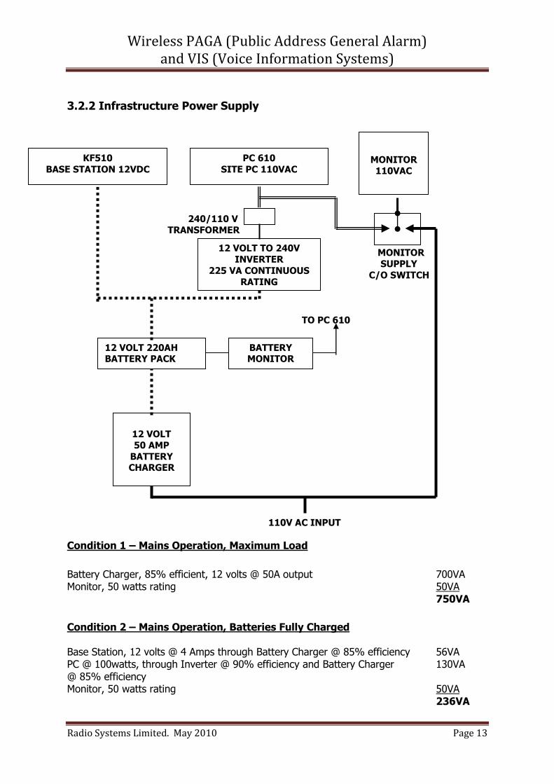
Condition 2 – Mains Operation, Batteries Fully Charged Base Station, 12 volts @ 4 Amps through Battery Charger @ 85% efficiency 56VA PC @ 100watts, through Inverter @ 90% efficiency and Battery Charger 130VA @ 85% efficiency Monitor, 50 watts rating 50VA 236VA
12 VOLT 50 AMP
BATTERY CHARGER
12 VOLT 220AH BATTERY PACK
12 VOLT TO 240V INVERTER
225 VA CONTINUOUS
RATING
KF510
BASE STATION 12VDC
PC 610
SITE PC 110VAC
MONITOR 110VAC
BATTERY MONITOR
Wireless PAGA (Public Address General Alarm) and VIS (Voice Information Systems)
Radio Systems Limited. May 2010 Page 14
Condition 3 – Mains Failure, Battery Operation
PC @ 100 watts, through Inverter @ 90% efficiency 110VA Base Station 12 volts @ 4 Amps 48VA 158VA
3.2.3 Serial Protocol for the Interface between Wired and Wireless Systems Since the wireless system will receive all its zone select and broadcast commands from the wired system, a commonly understood protocol is required. The following was agreed for this particular project. In general, the serial command structure used with Key equipment is 4800 or 9600 baud, 8 data bits, 1 stop bit and no parity. The messages are framed with <STX> and <ETX> characters (ASCII h02 and h03). The functional requirement is to select one or more Zones, which will be individual radios or groups of radios, and then connect to the selection for the broadcast. When the broadcast has finished, the radio circuit should be released to make it available for the set-up of the next message. This should be an explicit command, although it will time out after a pre-set period, if left idle. The numbers of individual radios and pre-set groups are 4 digit decimal numbers, and the selected combination of Zones could also be represented in that way. I suggest the following inputs: Select Zones, <STX>Azzzz<ETX> Commence Broadcast <STX>A8191<ETX> End Broadcast <STX>Z<ETX> There is a finite and variable time, depending on the number of zones selected, required to establish all the connections before the audio path is established. To prevent any risk of the start of the chimes being missed, it would be sensible to send progress information back, which could be used to trigger the announcement tones from the audio source. I suggest the following outputs: Zone zzzz selected. <STX>0zzzz<ETX> Audio established. <STX>3<ETX> Broadcast ended <STX>D<ETX>
Wireless PAGA (Public Address General Alarm) and VIS (Voice Information Systems)
Radio Systems Limited. May 2010 Page 15
3.2.4 Outstations
The enclosure is a 2mm mild steel cabinet, zinc plated and powder coated RAL7032.
It has a hinged door with lock
Cabinet and lock are IP65
The back plate is zinc plated mild steel, 550x550, four pillar supports 12 mm from corners, proposed layout as above
Back plate is on 10mm spacers from cabinet rear and max component height is battery @ 230mm, giving approx. 60mm clearance to door
A lifting handle will be fitted to each side by the manufacturer and the intention is to
have the enclosure on its back with door uppermost when in location
A 75mm alloy pole carrying speakers and aerial is to be fitted to side of enclosure without compromising IP rating
A 110volt chassis mount plug is to be fitted to enclosure with IP 65 seal
Battery
Charger
KM3000
Amplifier
Transfmr
ON OFF
Wireless PAGA (Public Address General Alarm) and VIS (Voice Information Systems)
Radio Systems Limited. May 2010 Page 16
4. Case Study - Operational Overview 4.1 Introduction This document should be read in conjunction with available drawings giving hardware configurations and architecture overviews. In depth documents are also available that describe Keynet and MPT1327 technology that form the basis of the WPA product range. The Wireless PA system infrastructure rack comprises a number of Key KF510 radio base stations using MPT1327 technology and Keynet software; an industrial computer, monitor and keyboard; backup batteries; battery charger and 110v inverter. In addition to battery back up, all infrastructure units are alarmed with modular graceful degradation. A hot standby can offer mission critical back up, in the unlikely event of catastrophic failure of the main infrastructure. Receivers can be permanently installed wherever mains power is available. Since each is battery backed, receivers can be temporarily operated at locations with no power. Speakers are integral to each Receiver but additional remote speakers can be added at any Receiver location. IS (ATEX) and non-ATEX Receivers are available. Industry standard of bespoke tone sets are available for pre-voice announcements and general alarm broadcasts. Pre-recorded messaging is an optional feature. Emergency tones and broadcasts are pre-emptive and take control of the system. The software described in this document is an example of how the WPA system functions and is controlled, enabling the Operator to select individual remote receivers and associated speakers, assign groups of speakers to zones and receive and process all system and receiver alarm messages. It also displays the current status of each of the zones in the wireless system, on the monitor. Radio Systems take the view that each WPA system will be user specific and a bespoke package. The configuration described below is a simpler example to demonstrate the general principles. It is followed by a number of available options.
4.2 Hardware
4.2.1 Equipment Power Up/Down Sequencing There is no requirement for any particular power sequencing of equipment during power up or down.
4.2.2 Fuse Power Up/Down Sequencing
When inserting fuses into a system that has had the fuses removed, it is recommended that the high current (60A) fuses be inserted first.
Wireless PAGA (Public Address General Alarm) and VIS (Voice Information Systems)
Radio Systems Limited. May 2010 Page 17
This is to avoid activation of the alarm buzzer in the battery charger that will occur if the (5A) voltage sense fuse for the battery charger is inserted prior to the high current fuses. No damage will occur if this sequence is not followed. The only effect is the sounding of the battery charger alarm buzzer. When removing fuses it is suggested that the reverse sequence is followed, i.e. remove the (5A) voltage sense fuse for the battery charger prior to the 60A fuses.
4.3 Software Start Up
The software is configured to automatically start as soon as the industrial pc is powered up. After start-up it will automatically display the main status screen, which shows the operational status of each of the wireless zones, the infrastructure and the status of any external alarm output, e.g. SCADA.
4.4 Status Screens
4.4.1 All zones present and working correctly
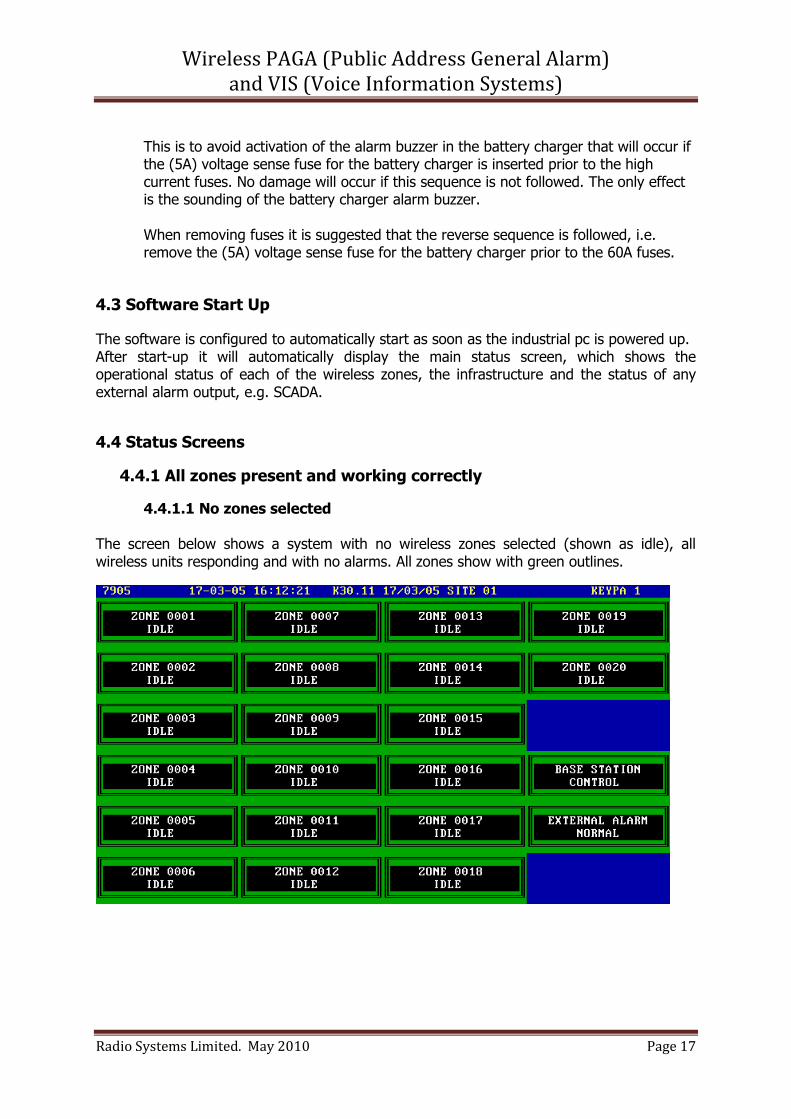
4.4.1.1 No zones selected
The screen below shows a system with no wireless zones selected (shown as idle), all wireless units responding and with no alarms. All zones show with green outlines.
Wireless PAGA (Public Address General Alarm) and VIS (Voice Information Systems)
Radio Systems Limited. May 2010 Page 18
4.4.1.2 All zones selected
The screen below shows a system with all wireless zones selected, all wireless units responding and with no alarms. All zones show with green outlines.
4.4.1.3 All zones in use The screen below shows a system with all wireless zones in use (broadcasting), all wireless units responding and with no alarms. All wireless zones show with brown outlines (indicating in use).
Wireless PAGA (Public Address General Alarm) and VIS (Voice Information Systems)
Radio Systems Limited. May 2010 Page 19
4.4.2 Some zones not responding
The screen below shows a system with wireless zones 11 and 14 not responding. None of the other zones are selected but they are responding and have no alarms. All zones without errors show with green outlines. The out of contact zones show with violet outlines and the external alarm shows in red (because of the loss of contact with zones 11 and 14).
Wireless PAGA (Public Address General Alarm) and VIS (Voice Information Systems)
Radio Systems Limited. May 2010 Page 20
4.5 Possible Status states
The possible states for each of the wireless zones are as follows.
State Border Colour Meaning
OFF LINE Grey Does not appear in normal operation. For diagnostic
use only
IDLE Green Unit operating correctly but not currently selected for
use
IN USE Brown Unit operating correctly and currently engaged in a
broadcast
SELECTED Green Unit operating correctly and selected as part of a broadcast group but not currently engaged in a
broadcast
IN USE ALARMED Violet Unit has reported a fault but is currently engaged in
a broadcast
NO CONTACT Violet The unit is not responding on the radio link
INHIBITED Grey-Green Band Does not appear in normal operation. For diagnostic
use only
FAULT Red White Flashing The unit has reported a fault
4.5.1 Clear Fault Indication
The only user input intended for end user use is a facility to clear an alarm state. This is achieved by pressing the space bar. The software will then prompt for the number of the zone to be cleared. Enter the number and press return. Any fault for that zone is then cleared.
4.5.2 Fault Finding Information
There is a single fault reporting mechanism for each wireless PA receiver and thus it is not possible to determine the precise cause of a reported fault without examining the unit that has reported the fault. There are two conditions that can occur that will give a zone FAULT indication.
Wireless PAGA (Public Address General Alarm) and VIS (Voice Information Systems)
Radio Systems Limited. May 2010 Page 21
4.5.4.2.1 110v Power failure In the case of a failure of the 110V supply to the receiver the system will indicate a FAULT. The receiver unit will continue to function on the internal backup battery. The faulty unit should be visited to determine the cause of the failure. It should be noted that a power failure indication is a single shot event. If the indication is cleared but 110v power is not restored to the affected unit, no further power failure warnings will be received. 4.5.2.2 Audio output failure In the case of the audio output level dropping below the fault detection threshold the system will indicate a FAULT. The faulty unit should be visited to determine the cause of the failure. Audio faults (if present) will be reported every time the faulty unit finishes a broadcast announcement. I.e. if the indication is cleared and the audio fault condition is still present the unit will fault again.
In addition to the zone FAULT indication there is also the zone ‘NO CONTACT’ indication. This occurs when the receiver unit is not in radio contact with the infrastructure rack. The most likely reason for this is that the relevant receiver unit has been turned off. The zone ‘NO CONTACT’ is will also trigger an external alarm fault and for this reason any unused receiver units should be kept powered up rather than switched off.
4.6 Other screens There are a number of other screen displays which may be accessed by pressing the Up / Down cursor keys. These screens are intended for diagnostic use only and are not for end user use. The status screen can be re-accessed by continuing to press the Up / Down cursor keys. It will cycle through each of the available displays and return to the status display. If the system is left displaying one of the diagnostic screens it will automatically return to the main status display after a few minutes.
4.7 Intercom Stations Optional fixed Intercom/telephone stations are available. From fixed positions around the plant, site operatives can make broadcast calls for a response from another operative. Anyone responding can select the intercom station to call back and the voice call can progress using integral IS or non IS handsets, as appropriate.
Wireless PAGA (Public Address General Alarm) and VIS (Voice Information Systems)
Radio Systems Limited. May 2010 Page 22
4.8 Plant Telephone to WPA calls The Keynet infrastructure can be interfaced to Plant PABX (or external PSTN) networks. This option would allow a telephone user to access the WPA system and make announcements. In addition, if option 10, below is used, telephone to handportable radio calls are available
4.9 Handportable Radio to WPA calls Due to the wireless nature of the infrastructure, integrated radio and WPA communications solutions are an option. If this option is exercised, for example for management grades, an ATEX or non ATEX handportable can be used to make radio to radio calls but can also be programmed to access the WPA system. This feature would enhance the Intercom Station facility in that operatives with enabled handportables could immediately respond to calls without having to walk to another Intercom Station.
4.10 Security and System Management
9 & 10 above provide a means of externally accessing what can be a mission critical and safety system. Keynet has a comprehensive Management function, where system access can be enabled or barred, with password access. All system activity is monitored, time stamped and archived.
Wireless PAGA (Public Address General Alarm) and VIS (Voice Information Systems)
Radio Systems Limited. May 2010 Page 23
5. Radio Systems Services The success and effectiveness of any project is reliant upon a whole range of skills and no matter how good the building blocks of a system might be, without those essential skills, projects can still fail to deliver. The Radio Systems team is qualified, experienced and moreover understands all the critical steps necessary for a first class delivery.
Requirements capture and documentation
Site surveys and propagation studies
Feasibility studies
Project Management and Budget Control
Risk analysis and mitigation
Preferred component procurement
In house software and hardware development
Component manufacturing facilities in ISO9000 environments
Quality Management and Control
Factory assembly of systems
Originating and implementing Factory Acceptance Test Documentation
Production of Method Statements and Risk Assessments
Site preparation, installation and commissioning
Originating and implementing Site Acceptance Test Documentation
As Built document pack production
Escrow Agreements
Warranty
Maintenance and Support contracts
Wireless PAGA (Public Address General Alarm) and VIS (Voice Information Systems)
Radio Systems Limited. May 2010 Page 24
6. Radio Systems Certification Radio Systems adheres to all current UK and EU legislation, has been certified by NQA and is regularly audited for continued compliance. ISO9001 Quality Certification
OHSAS18001 Health and Safety Certification ISO14001 Environmental Certification Compliant with Waste Electrical and Electronic Equipment Regulations 2006
Wireless PAGA (Public Address General Alarm) and VIS (Voice Information Systems)
Radio Systems Limited. May 2010 Page 25
7. Contacts The Radio Systems team is always ready to adopt a no obligation consultative sale approach. For initial discussions, contact details are as below. Sales Help Point Danny Abbs I.Eng MIET Business Development Director Radio Systems Limited M +44(0)7876 594444 mailto:[email protected] Technical and Development Help Point Andrew Barrett Technical Director Radio Systems Limited Zodiac House Unit 4A Calleva Park Aldermaston, Berks RG7 8HN. Tel +44(0)118 9811653 mailto:[email protected] Head and Registered Office Radio Systems Limited Highlode Industrial Estate Ramsey Cambridgeshire PE26 2RB England Tel+44(0)1487 815111 Fax +44 (0)1487 814973 www.radio-systems.co.uk
Statement of Copyright This is an unpublished work the copyright in which vests in Radio Systems Ltd. All rights reserved.
The information contained herein is confidential and the property of Radio Systems Ltd. and is
supplied without liability for error or omissions. No part may be reproduced, disclosed or used except as authorised by written permission. The copyright and foregoing restrictions on reproduction and use extend to all media in which the information may be embodied.