21
Boca Raton New York Wireless Security Handbook Aaron E. Earle © 2006 by Taylor & Francis Group, LLC
AU3378_TitlePage 11/16/05 8:59 AM Page 1
Boca Raton New York
WirelessSecurity
Handbook
Aaron E. Earle
© 2006 by Taylor & Francis Group, LLC
147
Chapter 10
Wireless Access Points
This chapter provides an overview of the many different types of wirelessequipment. It predominantly focuses on local area wireless equipment:wireless devices, who makes them, what technologies they support, andin what scenarios they should be used. There are many wireless manu-facturers out there, so many that an entire book could be put together tolook at each of them in detail. This chapter attempts to address as manyas possible, going in-depth only on the most commonly manufacturedtypes.
The single most important piece of equipment in a wireless networkis the access point. The access point is the piece of equipment thatpropagates the wireless signal into the air. There are many types of accesspoints from many different vendors. Some of them are made for smalloffice/home office (SOHO) and some are made for large enterprise deploy-ments. Cisco is one of the biggest players in the access point market;others include Proxim, Aruba, Symbol, and SonicWall. As discussed pre-viously, there is an overwhelming number of manufacturers trying to sellaccess points. Therefore, the focus stays with some of the most usedproducts in the industry.
10.1 Linksys Access Points
Linksys was acquired by Cisco in 2004. Thus far, Cisco has decided tokeep Linksys separate as a SOHO-only product line. This means that theequipment that Linksys has is primarily targeted at SOHO environments.
AU3378_book.fm Page 147 Monday, November 7, 2005 6:51 PM
© 2006 by Taylor & Francis Group, LLC
148
�
Wireless Security Handbook
One interesting thing that Linksys has done is move most of its wirelessproducts to an open source Linux kernel. A full list of all the Linksysaccess points with open source firmware is located below. This hasallowed Linksys to utilize some already-existing open source code toachieve lower development costs.
Using an open source code has sparked many groups who have hackedinto Linksys access points and made some interesting features availablewithin their own firmware code releases. Some of the most commonhacked firmware types are Wifibox, Batbox, and Alchemy. These firmwareversions are rather easy to install and can quickly improve many of thefeatures of a Linksys access point. Some of them have added functionalitythat was not present in the Linksys firmware releases.
Access points with open source firmware include:
�
WRT54G
�
WRE54G
�
WPG54G
�
WET54G
�
WAP55AG
�
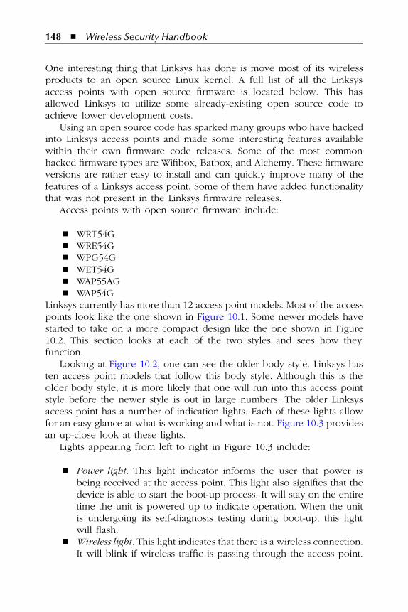
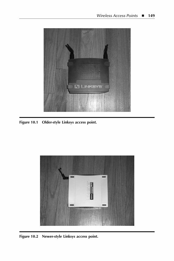
WAP54GLinksys currently has more than 12 access point models. Most of the accesspoints look like the one shown in Figure 10.1. Some newer models havestarted to take on a more compact design like the one shown in Figure10.2. This section looks at each of the two styles and sees how theyfunction.
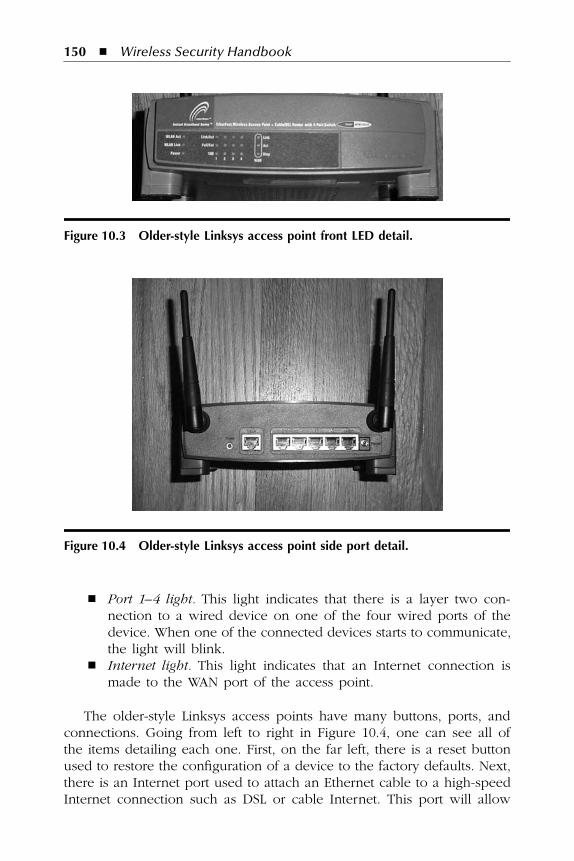
Looking at Figure 10.2, one can see the older body style. Linksys hasten access point models that follow this body style. Although this is theolder body style, it is more likely that one will run into this access pointstyle before the newer style is out in large numbers. The older Linksysaccess point has a number of indication lights. Each of these lights allowfor an easy glance at what is working and what is not. Figure 10.3 providesan up-close look at these lights.
Lights appearing from left to right in Figure 10.3 include:
�
Power light.
This light indicator informs the user that power isbeing received at the access point. This light also signifies that thedevice is able to start the boot-up process. It will stay on the entiretime the unit is powered up to indicate operation. When the unitis undergoing its self-diagnosis testing during boot-up, this lightwill flash.
�
Wireless light.
This light indicates that there is a wireless connection.It will blink if wireless traffic is passing through the access point.
AU3378_book.fm Page 148 Monday, November 7, 2005 6:51 PM
© 2006 by Taylor & Francis Group, LLC
Wireless Access Points
�
149
Figure 10.1 Older-style Linksys access point.
Figure 10.2 Newer-style Linksys access point.
AU3378_book.fm Page 149 Monday, November 7, 2005 6:51 PM
© 2006 by Taylor & Francis Group, LLC
150
�
Wireless Security Handbook
�
Port 1–4 light.
This light indicates that there is a layer two con-nection to a wired device on one of the four wired ports of thedevice. When one of the connected devices starts to communicate,the light will blink.
�
Internet light.
This light indicates that an Internet connection ismade to the WAN port of the access point.
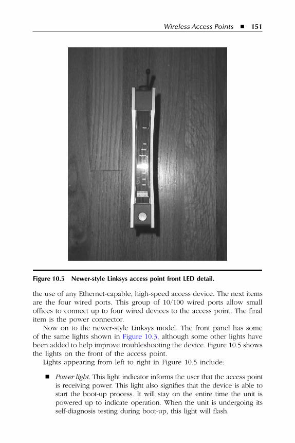
The older-style Linksys access points have many buttons, ports, andconnections. Going from left to right in Figure 10.4, one can see all ofthe items detailing each one. First, on the far left, there is a reset buttonused to restore the configuration of a device to the factory defaults. Next,there is an Internet port used to attach an Ethernet cable to a high-speedInternet connection such as DSL or cable Internet. This port will allow
Figure 10.3 Older-style Linksys access point front LED detail.
Figure 10.4 Older-style Linksys access point side port detail.
AU3378_book.fm Page 150 Monday, November 7, 2005 6:51 PM
© 2006 by Taylor & Francis Group, LLC
Wireless Access Points
�
151
the use of any Ethernet-capable, high-speed access device. The next itemsare the four wired ports. This group of 10/100 wired ports allow smalloffices to connect up to four wired devices to the access point. The finalitem is the power connector.
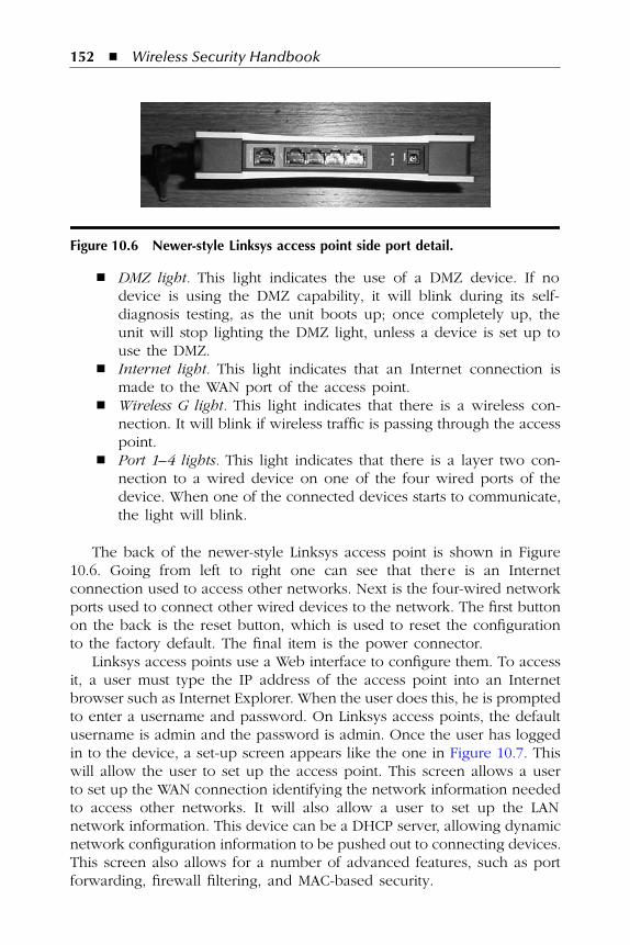
Now on to the newer-style Linksys model. The front panel has someof the same lights shown in Figure 10.3, although some other lights havebeen added to help improve troubleshooting the device. Figure 10.5 showsthe lights on the front of the access point.
Lights appearing from left to right in Figure 10.5 include:
�
Power light.
This light indicator informs the user that the access pointis receiving power. This light also signifies that the device is able tostart the boot-up process. It will stay on the entire time the unit ispowered up to indicate operation. When the unit is undergoing itsself-diagnosis testing during boot-up, this light will flash.
Figure 10.5 Newer-style Linksys access point front LED detail.
AU3378_book.fm Page 151 Monday, November 7, 2005 6:51 PM
© 2006 by Taylor & Francis Group, LLC
152
�
Wireless Security Handbook
�
DMZ light.
This light indicates the use of a DMZ device. If nodevice is using the DMZ capability, it will blink during its self-diagnosis testing, as the unit boots up; once completely up, theunit will stop lighting the DMZ light, unless a device is set up touse the DMZ.
�
Internet light.
This light indicates that an Internet connection ismade to the WAN port of the access point.
�
Wireless G light.
This light indicates that there is a wireless con-nection. It will blink if wireless traffic is passing through the accesspoint.
�
Port 1–4 lights.
This light indicates that there is a layer two con-nection to a wired device on one of the four wired ports of thedevice. When one of the connected devices starts to communicate,the light will blink.
The back of the newer-style Linksys access point is shown in Figure10.6. Going from left to right one can see that there is an Internetconnection used to access other networks. Next is the four-wired networkports used to connect other wired devices to the network. The first buttonon the back is the reset button, which is used to reset the configurationto the factory default. The final item is the power connector.
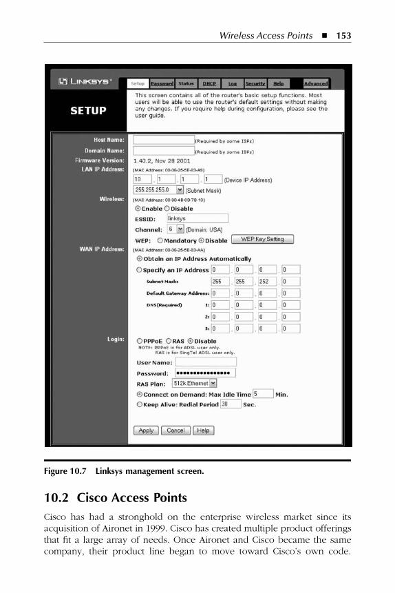
Linksys access points use a Web interface to configure them. To accessit, a user must type the IP address of the access point into an Internetbrowser such as Internet Explorer. When the user does this, he is promptedto enter a username and password. On Linksys access points, the defaultusername is admin and the password is admin. Once the user has loggedin to the device, a set-up screen appears like the one in Figure 10.7. Thiswill allow the user to set up the access point. This screen allows a userto set up the WAN connection identifying the network information neededto access other networks. It will also allow a user to set up the LANnetwork information. This device can be a DHCP server, allowing dynamicnetwork configuration information to be pushed out to connecting devices.This screen also allows for a number of advanced features, such as portforwarding, firewall filtering, and MAC-based security.
Figure 10.6 Newer-style Linksys access point side port detail.
AU3378_book.fm Page 152 Monday, November 7, 2005 6:51 PM
© 2006 by Taylor & Francis Group, LLC
Wireless Access Points
�
153
10.2 Cisco Access Points
Cisco has had a stronghold on the enterprise wireless market since itsacquisition of Aironet in 1999. Cisco has created multiple product offeringsthat fit a large array of needs. Once Aironet and Cisco became the samecompany, their product line began to move toward Cisco’s own code.
Figure 10.7 Linksys management screen.
AU3378_book.fm Page 153 Monday, November 7, 2005 6:51 PM
© 2006 by Taylor & Francis Group, LLC
154
�
Wireless Security Handbook
Once this happened, the market began to see the major benefit that Cisco’swireless access points bring to the table. They allow anyone familiar withCisco router and switch configurations to understand access point config-uration with ease. This was due to the fact that Cisco had integrated itsIOS code with the Aironet access point, creating an access point thatlooked, felt, and operated like any other Cisco router or switch.
Cisco has three main models of access points: 350, 1200, and 1100series. Each comes in a wide array of types that use different technologies.For example, the 1200 can use 802.11b, 802.11g, and 802.11a. This sectionlooks at all three types of access points and details what connections theyhave, what protocols and standards they support, and how they operate.
10.2.1 Cisco Aironet 350 Series
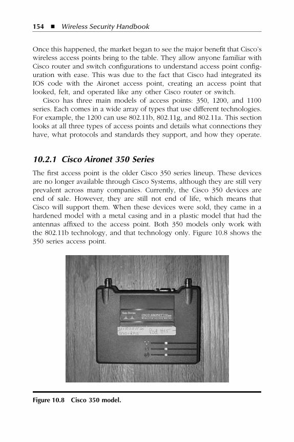
The first access point is the older Cisco 350 series lineup. These devicesare no longer available through Cisco Systems, although they are still veryprevalent across many companies. Currently, the Cisco 350 devices areend of sale. However, they are still not end of life, which means thatCisco will support them. When these devices were sold, they came in ahardened model with a metal casing and in a plastic model that had theantennas affixed to the access point. Both 350 models only work withthe 802.11b technology, and that technology only. Figure 10.8 shows the350 series access point.
Figure 10.8 Cisco 350 model.
AU3378_book.fm Page 154 Monday, November 7, 2005 6:51 PM
© 2006 by Taylor & Francis Group, LLC
Wireless Access Points
�
155
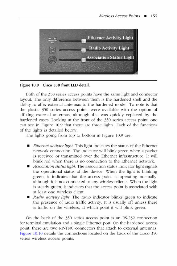
Both of the 350 series access points have the same light and connectorlayout. The only difference between them is the hardened shell and theability to affix external antennas to the hardened model. To note is thatthe plastic 350 series access points were available with the option ofaffixing external antennas, although this was quickly replaced by thehardened cases. Looking at the front of the 350 series access point, onecan see in Figure 10.9 that there are three lights. Each of the functionsof the lights is detailed below.
The lights going from top to bottom in Figure 10.9 are:
�
Ethernet activity light.
This light indicates the status of the Ethernetnetwork connection. The indicator will blink green when a packetis received or transmitted over the Ethernet infrastructure. It willblink red when there is no connection to the Ethernet network.
�
Association status light.
The association status indicator light signalsthe operational status of the device. When the light is blinkinggreen, it indicates that the access point is operating normally,although it is not connected to any wireless clients. When the lightis steady green, it indicates that the access point is associated withat least one wireless client.
�
Radio activity light.
The radio indicator blinks green to indicatethe presence of radio traffic activity. It is usually off unless thereis traffic on the wireless, at which point it will blink green.
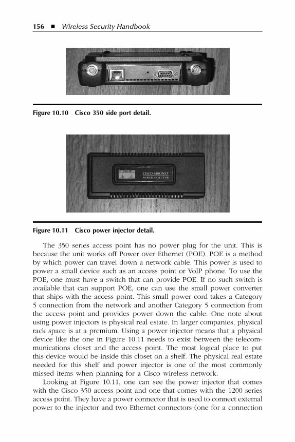
On the back of the 350 series access point is an RS-232 connectionfor terminal emulation and a single Ethernet port. On the hardened accesspoint, there are two RP-TNC connectors that attach to external antennas.Figure 10.10 details the connections located on the back of the Cisco 350series wireless access points.
Figure 10.9 Cisco 350 front LED detail.
AU3378_book.fm Page 155 Monday, November 7, 2005 6:51 PM
© 2006 by Taylor & Francis Group, LLC
156
�
Wireless Security Handbook
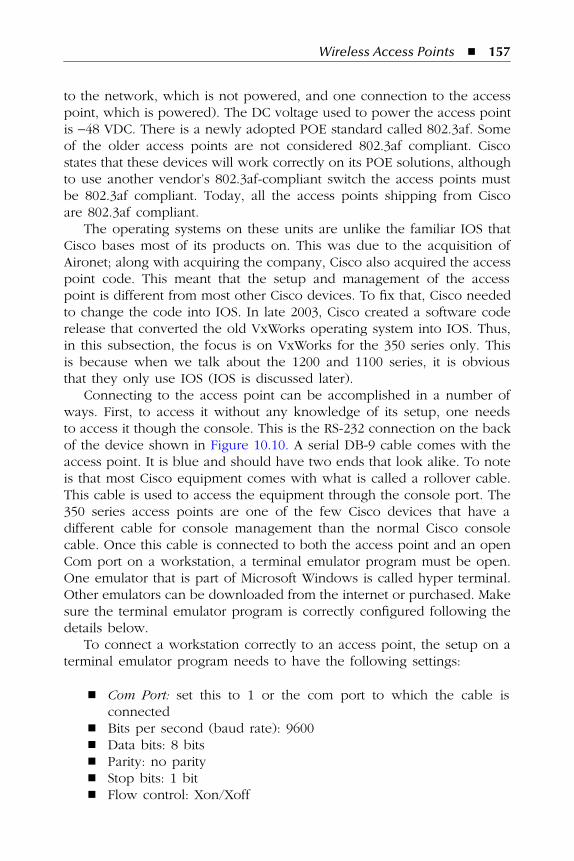
The 350 series access point has no power plug for the unit. This isbecause the unit works off Power over Ethernet (POE). POE is a methodby which power can travel down a network cable. This power is used topower a small device such as an access point or VoIP phone. To use thePOE, one must have a switch that can provide POE. If no such switch isavailable that can support POE, one can use the small power converterthat ships with the access point. This small power cord takes a Category5 connection from the network and another Category 5 connection fromthe access point and provides power down the cable. One note aboutusing power injectors is physical real estate. In larger companies, physicalrack space is at a premium. Using a power injector means that a physicaldevice like the one in Figure 10.11 needs to exist between the telecom-munications closet and the access point. The most logical place to putthis device would be inside this closet on a shelf. The physical real estateneeded for this shelf and power injector is one of the most commonlymissed items when planning for a Cisco wireless network.
Looking at Figure 10.11, one can see the power injector that comeswith the Cisco 350 access point and one that comes with the 1200 seriesaccess point. They have a power connector that is used to connect externalpower to the injector and two Ethernet connectors (one for a connection
Figure 10.10 Cisco 350 side port detail.
Figure 10.11 Cisco power injector detail.
AU3378_book.fm Page 156 Monday, November 7, 2005 6:51 PM
© 2006 by Taylor & Francis Group, LLC
Wireless Access Points
�
157
to the network, which is not powered, and one connection to the accesspoint, which is powered). The DC voltage used to power the access pointis
−
48 VDC. There is a newly adopted POE standard called 802.3af. Someof the older access points are not considered 802.3af compliant. Ciscostates that these devices will work correctly on its POE solutions, althoughto use another vendor’s 802.3af-compliant switch the access points mustbe 802.3af compliant. Today, all the access points shipping from Ciscoare 802.3af compliant.
The operating systems on these units are unlike the familiar IOS thatCisco bases most of its products on. This was due to the acquisition ofAironet; along with acquiring the company, Cisco also acquired the accesspoint code. This meant that the setup and management of the accesspoint is different from most other Cisco devices. To fix that, Cisco neededto change the code into IOS. In late 2003, Cisco created a software coderelease that converted the old VxWorks operating system into IOS. Thus,in this subsection, the focus is on VxWorks for the 350 series only. Thisis because when we talk about the 1200 and 1100 series, it is obviousthat they only use IOS (IOS is discussed later).
Connecting to the access point can be accomplished in a number ofways. First, to access it without any knowledge of its setup, one needsto access it though the console. This is the RS-232 connection on the backof the device shown in Figure 10.10. A serial DB-9 cable comes with theaccess point. It is blue and should have two ends that look alike. To noteis that most Cisco equipment comes with what is called a rollover cable.This cable is used to access the equipment through the console port. The350 series access points are one of the few Cisco devices that have adifferent cable for console management than the normal Cisco consolecable. Once this cable is connected to both the access point and an openCom port on a workstation, a terminal emulator program must be open.One emulator that is part of Microsoft Windows is called hyper terminal.Other emulators can be downloaded from the internet or purchased. Makesure the terminal emulator program is correctly configured following thedetails below.
To connect a workstation correctly to an access point, the setup on aterminal emulator program needs to have the following settings:
�
Com Port:
set this to 1 or the com port to which the cable isconnected
�
Bits per second (baud rate): 9600
�
Data bits: 8 bits
�
Parity: no parity
�
Stop bits: 1 bit
�
Flow control: Xon/Xoff
AU3378_book.fm Page 157 Monday, November 7, 2005 6:51 PM
© 2006 by Taylor & Francis Group, LLC
158
�
Wireless Security Handbook
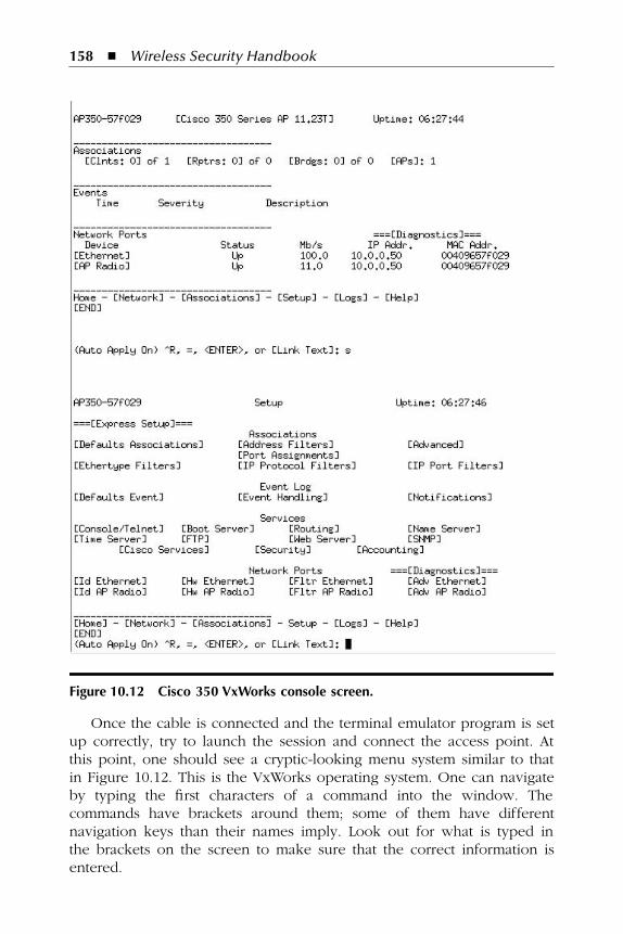
Once the cable is connected and the terminal emulator program is setup correctly, try to launch the session and connect the access point. Atthis point, one should see a cryptic-looking menu system similar to thatin Figure 10.12. This is the VxWorks operating system. One can navigateby typing the first characters of a command into the window. Thecommands have brackets around them; some of them have differentnavigation keys than their names imply. Look out for what is typed inthe brackets on the screen to make sure that the correct information isentered.
Figure 10.12 Cisco 350 VxWorks console screen.
AU3378_book.fm Page 158 Monday, November 7, 2005 6:51 PM
© 2006 by Taylor & Francis Group, LLC
Wireless Access Points
�
159
Having learned how to connect to the Cisco 350 access point via theconsole, there some other ways of setting up and managing this device.This device has a built-in Web interface like the one on the Linksys accesspoints. To access it, one must know the IP address of the unit so onecan enter that into a Web browser. By default, all Cisco access points gettheir address via DHCP. This makes finding the access point’s IP addressdifficult the first time. Cisco stepped in and created a tool called IP setuputility (IPSU) that can find the access point’s IP address from its MACaddress. For this tool to work, it must be installed on a workstation thatis on the same network segment as the access point. Once this softwareis installed, one can launch the application, type in the MAC address ofthe access point, and it will show the IP address. The MAC address ofany Cisco access point is written on the back of the unit.
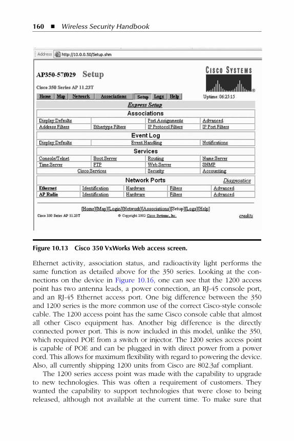
Now that the IP address is known, connecting to the access point ispossible through the Web. To do so, just type in the http:// and the IPaddress of the access point. This will bring up the Web interface. ForVxWorks, this method is the preferred method of configuration. One keyadvantage that Cisco has made for itself in the large enterprise space isthe ability to create configuration scripts for almost all of its products.With VxWorks, still being an Aironet/Cisco code, this was not achieved.This meant that the ability to easily script the configuration in VxWorkswas rather difficult. Looking at Figure 10.13, one can see what the Webinterface looks like for the VxWorks operating system.
The final method of accessing the access point’s management functionsis through telnet. This has a very similar look and feel to the consolealthough it can be done remotely from any connection with IP connectivity.In some newer versions of code, Secure Shell (SSH) can also be used.Telnet is prone to eavesdropping because its authentication takes placein cleartext. To telnet into an access point, all one needs is a telnetprogram. UNIX and Windows both have telnet ability right from a com-mand line or shell. Most Cisco equipment can perform a telnet actionfrom one device to another.
10.2.2 Cisco 1200 Series Access Point
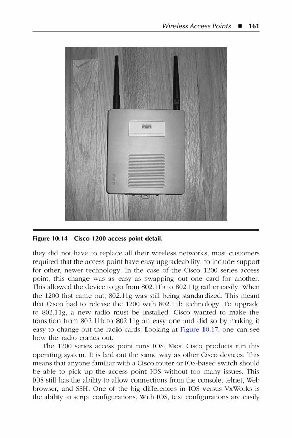
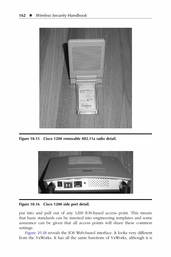
Now to the Cisco 1200 series access points. These all come in a plenum-rated metal case; the case is shown in Figure 10.14. These access pointshave the latest and greatest features available from Cisco. They are capableof supporting 802.11b, 802.11g, and 802.11a simultaneously. To support802.11a, a paddle card must be installed into the access point. This cardis shown in Figure 10.15.
Delving deeper into the access point itself, one can see from Figure10.14 that the access point has the same LED layout as the 350. Each
AU3378_book.fm Page 159 Monday, November 7, 2005 6:51 PM
© 2006 by Taylor & Francis Group, LLC
160
�
Wireless Security Handbook
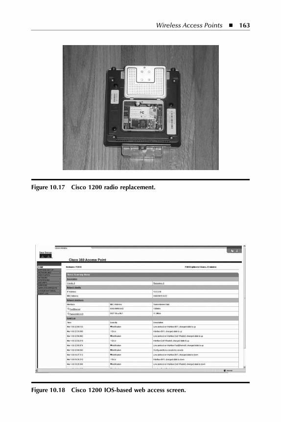
Ethernet activity, association status, and radioactivity light performs thesame function as detailed above for the 350 series. Looking at the con-nections on the device in Figure 10.16, one can see that the 1200 accesspoint has two antenna leads, a power connection, an RJ-45 console port,and an RJ-45 Ethernet access port. One big difference between the 350and 1200 series is the more common use of the correct Cisco-style consolecable. The 1200 access point has the same Cisco console cable that almostall other Cisco equipment has. Another big difference is the directlyconnected power port. This is now included in this model, unlike the 350,which required POE from a switch or injector. The 1200 series access pointis capable of POE and can be plugged in with direct power from a powercord. This allows for maximum flexibility with regard to powering the device.Also, all currently shipping 1200 units from Cisco are 802.3af compliant.
The 1200 series access point was made with the capability to upgradeto new technologies. This was often a requirement of customers. Theywanted the capability to support technologies that were close to beingreleased, although not available at the current time. To make sure that
Figure 10.13 Cisco 350 VxWorks Web access screen.
AU3378_book.fm Page 160 Monday, November 7, 2005 6:51 PM
© 2006 by Taylor & Francis Group, LLC
Wireless Access Points
�
161
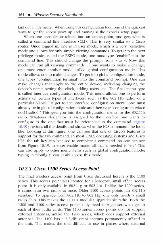
they did not have to replace all their wireless networks, most customersrequired that the access point have easy upgradeability, to include supportfor other, newer technology. In the case of the Cisco 1200 series accesspoint, this change was as easy as swapping out one card for another.This allowed the device to go from 802.11b to 802.11g rather easily. Whenthe 1200 first came out, 802.11g was still being standardized. This meantthat Cisco had to release the 1200 with 802.11b technology. To upgradeto 802.11g, a new radio must be installed. Cisco wanted to make thetransition from 802.11b to 802.11g an easy one and did so by making iteasy to change out the radio cards. Looking at Figure 10.17, one can seehow the radio comes out.
The 1200 series access point runs IOS. Most Cisco products run thisoperating system. It is laid out the same way as other Cisco devices. Thismeans that anyone familiar with a Cisco router or IOS-based switch shouldbe able to pick up the access point IOS without too many issues. ThisIOS still has the ability to allow connections from the console, telnet, Webbrowser, and SSH. One of the big differences in IOS versus VxWorks isthe ability to script configurations. With IOS, text configurations are easily
Figure 10.14 Cisco 1200 access point detail.
AU3378_book.fm Page 161 Monday, November 7, 2005 6:51 PM
© 2006 by Taylor & Francis Group, LLC
162
�
Wireless Security Handbook
put into and pull out of any 1200 IOS-based access point. This meansthat basic standards can be inserted into engineering templates and someassurance can be given that all access points will share these commonsettings.
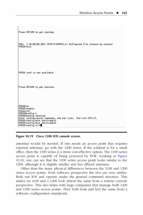
Figure 10.18 reveals the IOS Web-based interface. It looks very differentfrom the VxWorks. It has all the same functions of VxWorks, although it is
Figure 10.15 Cisco 1200 removable 802.11a radio detail.
Figure 10.16 Cisco 1200 side port detail.
AU3378_book.fm Page 162 Monday, November 7, 2005 6:51 PM
© 2006 by Taylor & Francis Group, LLC
Wireless Access Points
�
163
Figure 10.17 Cisco 1200 radio replacement.
Figure 10.18 Cisco 1200 IOS-based web access screen.
AU3378_book.fm Page 163 Monday, November 7, 2005 6:51 PM
© 2006 by Taylor & Francis Group, LLC
164
�
Wireless Security Handbook
laid out a little neater. When using this configuration tool, one of the quickestways to get the access point up and running is the express setup page.
When one consoles or telnets into an access point, one gets what iscalled a command line interface (CLI). This is very similar to a Ciscorouter. Once logged in, one is in user mode, which is a very restrictivemode and allows for only simple viewing commands. To get into the nextprivilege mode, called the EXEC mode, one must type “enable” into thecommand line. This should change the prompt from > to #. Now thismode can run all viewing commands. If one wants to make a change,one must enter another mode, called global configuration mode. Thismode allows one to make changes. To get into global configuration mode,one types “configuration terminal” into the command prompt. One canmake changes that apply to the entire device, including changing thedevice’s name, setting the clock, adding users, etc. The final menu typeis called interface configuration mode. This menu allows one to performactions on certain types of interfaces, such as the 802.11b radio, or aparticular VLAN. To get to the interface configuration menu, one mustalready be in global configuration mode and then type “configure interfacedot11radio0.” This gets you into the configuration menu for the 802.11bradio. Whatever designator is assigned to the interface one wants toconfigure is the one that must be referenced in the command. Figure10.19 provides all the details and shows what the IOS command line lookslike. Looking at this figure, one can see that one of Cisco’s features issupport for the tab command. In most UNIX operating systems and CiscoIOS, the tab key can be used to complete a command. As one can seefrom Figure 10.19, to enter enable mode, all that is needed is “en.” Thiscan also apply to other menu items such as global configuration mode;typing in “config t” can easily access this mode.
10.2.3 Cisco 1100 Series Access Point
The final wireless access point from Cisco discussed herein is the 1100series. This access point was created for a low-cost, small office accesspoint. It is only available in 802.11g or 802.11a. Unlike the 1200 series,it cannot run two radios at once. Older 1100 access points ran 802.11bstandard. To upgrade from 802.11b to 802.11g, one only needs a smallradio chip. This makes the 1100 a modular upgradeable radio. Both the1200 and 1100 series access points only need a single screw to get toeach of their radio cards. The 1100 series access points do not supportexternal antennas, unlike the 1200 series, which does support externalantennas. The 1100 has a 2.2-dBi omni antenna permanently affixed tothe unit. This makes the unit difficult to use in places where external
AU3378_book.fm Page 164 Monday, November 7, 2005 6:51 PM
© 2006 by Taylor & Francis Group, LLC
Wireless Access Points
�
165
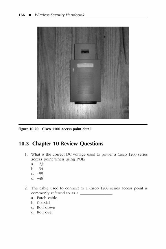
antennas would be needed. If one needs an access point that requiresexternal antennas, go with the 1200 series. If the solution is for a smalloffice, then the 1100 series is a more cost-effective option. The 1100 seriesaccess point is capable of being powered by POE. Looking at Figure10.20, one can see that the 1100 series access point looks similar to the1200, although it is slightly smaller and has affixed antennas.
Other than the many physical differences between the 1100 and 1200series access points, from software perspective the two are very similar.Both run IOS and operate under the general command structure. Thismakes an 1100 and a 1200 look almost the same from a remote consoleperspective. This also helps with large companies that manage both 1200and 1100 series access points. They both look and feel the same from asoftware configuration standpoint.
Figure 10.19 Cisco 1200 IOS console screen.
AU3378_book.fm Page 165 Monday, November 7, 2005 6:51 PM
© 2006 by Taylor & Francis Group, LLC
166
�
Wireless Security Handbook
10.3 Chapter 10 Review Questions
1. What is the correct DC voltage used to power a Cisco 1200 seriesaccess point when using POE?a.
−
23b. –34c. –99d.
−
48
2. The cable used to connect to a Cisco 1200 series access point iscommonly referred to as a ________________.a. Patch cableb. Coaxialc. Roll downd. Roll over
Figure 10.20 Cisco 1100 access point detail.
AU3378_book.fm Page 166 Monday, November 7, 2005 6:51 PM
© 2006 by Taylor & Francis Group, LLC


