16
WIRELESS SECURITY SYSTEM Installation Instructions & Owner’s Manual
WIRELESSSECURITYSYSTEM
Installation Instructions& Owner’s Manual
FRONT COVER1 OF 16
INS
TR
, IN
ST
ALL
AT
ION
, SS
D8
Line
ar P
/N: 2
1558
3 B
Mat
eria
l: 20
# W
hite
Mea
d B
ond
with
80#
Whi
te C
oate
d C
over
Ink:
Bla
ckS
ize:
8.5
00"
x 5.
500"
Sca
le: 1
-1

INTRODUCTION
Congratulations for selecting this Wireless Security System. This Consoleincorporates many of the advanced and sophisticated features ofprofessionally installed systems, yet it is wireless, and you can easily installit yourself. You can also expand and customize the system to fit yourspecific needs.
This system is a Residential Security System designed for apartments orhomes. Many insurance companies offer discounts on homeowner’s andrenter’s policies when a security system is installed. Discount credits varywith different companies and generally increase in savings with an increasein the level of protection. Ask your insurance agent about available savingsfor you.
NOTE: Some cities and municipalities may require an alarm systempermit. Check with your local authorities before installing this system.
The Console and its accessories are designed and manufactured by theoldest wireless security company in North America. You can look aheadto many years of reliable service and peace of mind with this system onguard for you and your family.
This wireless security system uses battery powered sensors to monitordoors and windows. They each use a small magnet, attached to the dooror window, that triggers the sensor when the portal opens or closes. TheConsole’s indicators display the open or closed status of each protectedopening. For ease of installation, this system is pre-programmed at thefactory. The two door/window sensors supplied have already beenprogrammed as Sensor #1 and #2. A total of eight sensors may be usedwith the Console.
TABLE OF CONTENTS
INSIDE FRONT COVER2 OF 16
SYSTEM COMPONENTS . . . . . . . . . . . . . . 1COMPATIBLE ACCESSORIES . . . . . . . . . . . 1SYSTEM FEATURES . . . . . . . . . . . . . . . . 2CONSOLE LOCATION . . . . . . . . . . . . . . . . 3CONNECT ANTENNA . . . . . . . . . . . . . . . . 3CONSOLE MOUNTING . . . . . . . . . . . . . . . 3APPLY POWER & CREATE YOUR SECRET CODE 3TEST PRE-PROGRAMMED SENSORS . . . . . . . 4SENSOR RESPONSE SWITCH . . . . . . . . . . . 4EXAMPLE SENSOR INSTALLATION . . . . . . . . 4OPTIONAL MAGNET SPACER . . . . . . . . . . . 5SENSOR INSTALLATION ON DOOR . . . . . . . . 5SENSOR INSTALLATION ON WINDOW . . . . . . 5TEST INSTALLED SENSORS . . . . . . . . . . . . 5CONSOLE OPERATION . . . . . . . . . . . . . . . 6
THE OFF MODE . . . . . . . . . . . . . . . . . . . 6THE CHIME MODE . . . . . . . . . . . . . . . . . 6THE HOME MODE . . . . . . . . . . . . . . . . . 7THE AWAY MODE . . . . . . . . . . . . . . . . . 7INSTALLING SYSTEM BACKUP BATTERIES . . . 8SYSTEM TESTING . . . . . . . . . . . . . . . . . 8CONNECTING AN EXTERNAL SPEAKER . . . . . 9CONNECTING A VOICE DIALER . . . . . . . . . . 9ADDING AND REMOVING SENSORS . . . . . . . 10TWO-BUTTON REMOTE CONTROL ACCESSORY 11MOTION DETECTOR ACCESSORY . . . . . . . . 11GLASS BREAK SENSOR ACCESSORY . . . . . . 11MAGNETIC SWITCH ACCESSORY . . . . . . . . 12REPLACING SENSOR BATTERIES . . . . . . . . 12CHANGING YOUR SECRET CODE . . . . . . . . 12RESETTING THE CONSOLE . . . . . . . . . . . . 13FCC NOTES . . . . . . . . . . . . . . . . . . . . . 13
INS
TR
, IN
ST
ALL
AT
ION
, SS
D8
Line
ar P
/N: 2
1558
3 B
Mat
eria
l: 20
# W
hite
Mea
d B
ond
with
80#
Whi
te C
oate
d C
over
Ink:
Bla
ckS
ize:
8.5
00"
x 5.
500"
Sca
le: 1
-1

SYSTEM COMPONENTS
COMPATIBLE ACCESSORIES
3 OF 16
DOOR/WINDOWSENSORS (2)
AC ADAPTER
SSD8CONSOLE
SENSOR
MAGNET
WIRELESS2-BUTTONREMOTE
CONTROL
WIRELESSMOTION
DETECTOR
WIRELESSDOOR/WINDOW
SENSOR
EXTERNALSPEAKER
GLASS BREAKSENSOR
MAGNETICSWITCH
NOTE: OTHER SSD ACCESSORIESSOLD ARE NOT COMPATIBLE WITHTHE SSD8 CONSOLE
EACH OF THESE ACCESSORIES ARE COMPATIBLEWITH THE SSD8 CONSOLE
A TOTAL OF EIGHT WIRELESS SENSORSCAN BE USED WITH EACH SYSTEM
INS
TR
, IN
ST
ALL
AT
ION
, SS
D8
Line
ar P
/N: 2
1558
3 B
Mat
eria
l: 20
# W
hite
Mea
d B
ond
with
80#
Whi
te C
oate
d C
over
Ink:
Bla
ckS
ize:
8.5
00"
x 5.
500"
Sca
le: 1
-1
1

SYSTEM FEATURES
1. SPEAKER★ Sounds unique sirens for burglary or emergency.★ Alarm siren stops automatically after five minutes.★ Sounds mode selection gongs and beeps.★ Sounds keyclicks as keypad keys are pressed.★ Sounds beeps during exit and entry time delays in the Away Mode.★ Sounds “ding-dong” in Chime Mode when protected door or window opens.★ Console has connections for an external speaker.
2. MODE INDICATORS★ Displays which mode the system is currently in.★ During AC power failures, the active mode indicator will blink after 30 seconds.★ The Away Mode indicator will blink during the exit delay time.
3. MODE BUTTONS★ Used to change the operating mode of the Console.★ From the Off Mode, pressing [CHIME], [HOME], or [AWAY] for 2 seconds will arm the system to that mode.★ From Chime Mode, pressing [HOME] or [AWAY] for 2 seconds will arm the system to that mode.★ To disarm the system, your secret code must be entered on the keypad first, then pressing [OFF] or [CHIME]
will switch the system to that mode.4. KEYPAD
★ Used to enter your secret code before disarming the system.★ Used during system programming to select sensor location numbers or to change your secret code.★ A beep sounds from the speaker as each key is pressed.★ The [∗] key resets the keypad in case the wrong keys are pressed.
5. SENSOR STATUS INDICATORS★ Display the status of each of the system’s wireless sensors.★ When a protected door or window is open, its sensor status indicator will light.★ If a wireless sensor has a low battery, its sensor status indicator will briefly flash until the low battery is replaced.★ If an alarm is triggered by a sensor, its sensor status indicator will slowly blink on and off until the system’s
mode is changed twice.★ Used during programming to show if sensor location is empty or full.★ Area next to the indicators allows labeling each sensor location with the pre-printed labels supplied.
6. WALL MOUNTING BRACKET★ Snaps onto the Console for mounting the unit on the wall.★ Built-in wire holder to store excess AC adapter wire.
7. VOICE DIALER JACK★ For connection to the optional telephone voice dialer.
8. ANTENNA SCREW★ Used to secure the whip antenna in place.
9. BATTERY ACCESS DOOR★ Provides access to the location for the two backup batteries.★ Two 9-volt alkaline batteries are recommended to provide uninterrupted operation during AC power loss.
10. VOLUME CONTROL★ Controls the volume of the system’s advisory beeps, gongs, and tones.★ Does not affect the volume of the system’s sirens.
4 OF 16
1
2
3
4
5
6
7
9
10
8
INS
TR
, IN
ST
ALL
AT
ION
, SS
D8
Line
ar P
/N: 2
1558
3 B
Mat
eria
l: 20
# W
hite
Mea
d B
ond
with
80#
Whi
te C
oate
d C
over
Ink:
Bla
ckS
ize:
8.5
00"
x 5.
500"
Sca
le: 1
-1
2

CONSOLE LOCATION• The Console must be located where it can easily
receive the wireless signals from each of thesystem’s sensors.
• Centrally locate the Console among the system’ssensors.
• Keep the Console away from large metal objects.• You will have 45 seconds to disarm the system when
entering. Be sure you can get to the Console fromthe entry door in 45 seconds.
• Locate the Console near a 115 VAC outlet that is notcontrolled by a wall switch.
CONNECT ANTENNA• Loosen screw by antenna hole one turn.
• Insert the whip antenna into the antenna hole on theend of the Console then tighten the antenna screwon the Console bottom.
• If the Console is going to be used on a flat surface,bend the antenna upward (see figure).
CONSOLE MOUNTING• The Console can be mounted to a wall
(recommended) or placed on a flat surface.• Four small plastic anti-mar “feet” are provided to
apply to the unit when used on a flat surface.• A wall mounting bracket, screws, and anchors are
provided to hang the unit on the wall.
APPLY POWER & CREATE YOUR SECRET CODE• Plug the AC adapter into the power outlet not
controlled by a wall switch. Wait about 5 seconds forthe unit’s self-test to complete.
• On the keypad, enter a one to five digit secret code,then press [CHIME].
• Verify your secret code by entering it again andpressing [OFF], the unit should switch to the OffMode (if it doesn’t, see Resetting the Console).
• Write down your secret code.• To change your secret code see the “Changing Your
Secret Code” section of this manual.
5 OF 16
CENTRALLY LOCATETHE CONSOLE
LOOSEN SCREW BY ANTENNA HOLEONE TURN
SLIDE ANTENNA INTOANTENNA HOLE THENTIGHTEN ANTENNASCREW
ANTENNAHOLE
IF THE CONSOLE ISNOT GOING TO BEWALL MOUNTED,BEND ANTENNA UPWARD
FOR WALL MOUNTING, ATTACH THEMOUNTING PLATE TO THE WALL WITHTHE SCREWS AND ANCHORS PROVIDED
EXCESS WIRE CAN BEWOUND AROUND POSTS
HOOK CONSOLE ONTOTOP POSTS ON MOUNTINGPLATE, THEN SNAP UNITONTO THE BOTTOM POSTS
NOTE: TO RELEASE UNITFROM PLATE, PRESS INTHE BOTTOM POSTS
Chime
ENTER A 1-5DIGIT SECRETCODE ANDPRESS CHIME
Off
ENTER THE SECRETCODE AND PRESSOFF TO TEST THENEW CODE
PLUG AC ADAPTERINTO OUTLET
INS
TR
, IN
ST
ALL
AT
ION
, SS
D8
Line
ar P
/N: 2
1558
3 B
Mat
eria
l: 20
# W
hite
Mea
d B
ond
with
80#
Whi
te C
oate
d C
over
Ink:
Bla
ckS
ize:
8.5
00"
x 5.
500"
Sca
le: 1
-1
3
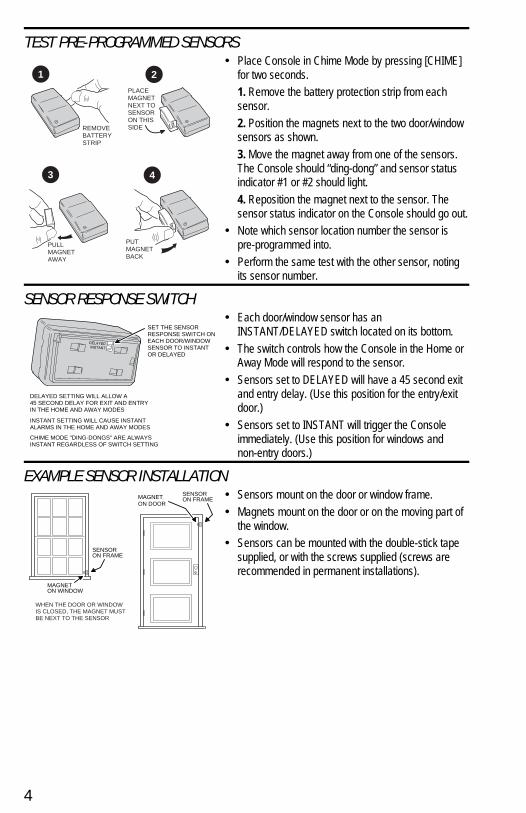
TEST PRE-PROGRAMMED SENSORS• Place Console in Chime Mode by pressing [CHIME]
for two seconds.1. Remove the battery protection strip from eachsensor.2. Position the magnets next to the two door/windowsensors as shown.3. Move the magnet away from one of the sensors.The Console should “ding-dong” and sensor statusindicator #1 or #2 should light.4. Reposition the magnet next to the sensor. Thesensor status indicator on the Console should go out.
• Note which sensor location number the sensor ispre-programmed into.
• Perform the same test with the other sensor, notingits sensor number.
SENSOR RESPONSE SWITCH• Each door/window sensor has an
INSTANT/DELAYED switch located on its bottom.• The switch controls how the Console in the Home or
Away Mode will respond to the sensor.• Sensors set to DELAYED will have a 45 second exit
and entry delay. (Use this position for the entry/exitdoor.)
• Sensors set to INSTANT will trigger the Consoleimmediately. (Use this position for windows andnon-entry doors.)
EXAMPLE SENSOR INSTALLATION• Sensors mount on the door or window frame.• Magnets mount on the door or on the moving part of
the window. • Sensors can be mounted with the double-stick tape
supplied, or with the screws supplied (screws arerecommended in permanent installations).
6 OF 16
REMOVEBATTERYSTRIP
PLACEMAGNETNEXT TOSENSORON THISSIDE
PULLMAGNETAWAY
PUTMAGNETBACK
3
1 2
4
MAGNETON WINDOW
SENSORON FRAME
SENSORON FRAMEMAGNET
ON DOOR
WHEN THE DOOR OR WINDOWIS CLOSED, THE MAGNET MUSTBE NEXT TO THE SENSOR
SET THE SENSORRESPONSE SWITCH ONEACH DOOR/WINDOWSENSOR TO INSTANTOR DELAYED
DELAYED SETTING WILL ALLOW A45 SECOND DELAY FOR EXIT AND ENTRYIN THE HOME AND AWAY MODES
INSTANT SETTING WILL CAUSE INSTANTALARMS IN THE HOME AND AWAY MODES
CHIME MODE "DING-DONGS" ARE ALWAYSINSTANT REGARDLESS OF SWITCH SETTING
INS
TR
, IN
ST
ALL
AT
ION
, SS
D8
Line
ar P
/N: 2
1558
3 B
Mat
eria
l: 20
# W
hite
Mea
d B
ond
with
80#
Whi
te C
oate
d C
over
Ink:
Bla
ckS
ize:
8.5
00"
x 5.
500"
Sca
le: 1
-1
4
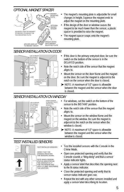
OPTIONAL MAGNET SPACER• The magnet’s mounting plate is adjustable for small
changes in height. Squeeze the magnet ends toadjust the magnet on the mounting plate.
• If the design of the door or window causes themagnet to be much lower than the sensor, a plasticspacer is provided to raise the magnet.
• The magnet spacer snaps onto the magnet’smounting plate.
SENSOR INSTALLATION ON DOOR• If this door is the primary entry/exit door, be sure the
switch on the bottom of the sensor is in theDELAYED position.
• Note the notch side of the sensor that the magnetaligns to.
• Mount the sensor on the door frame and the magneton the door. Be sure the magnet is adjacent to thenotch on the sensor when the door is closed.
➤ NOTE: A maximum of 1/2" space is allowablebetween the magnet and the sensor when the dooris closed.
SENSOR INSTALLATION ON WINDOW• For windows, set the switch on the bottom of the
sensor to the INSTANT position.• Note the notch side of the sensor that the magnet
aligns to.• Mount the sensor on the window frame and the
magnet on the window. Be sure the magnet isadjacent to the notch on the sensor when thewindow is closed.
➤ NOTE: A maximum of 1/2" space is allowablebetween the magnet and the sensor when thewindow is closed.
TEST INSTALLED SENSORS• Test the installed sensors with the Console in the
Chime Mode.• Open one protected opening and verify that the
Console sounds a “ding-dong” and that a sensorstatus indicator lights.
• Apply a sensor label that describes the opening nextto the lit status indicator.
• Close the protected opening and verify that itssensor status indicator goes out.
• Repeat the test with any other sensors installed andapply a sensor label describing its location.
7 OF 16
USE SCREWSOR DOUBLE-STICK TAPETO ATTACHSENSORMOUNTINGPLATES
SNAP SENSOR& MAGNET ONTOMOUNTINGPLATES
USE SCREWSOR DOUBLE-STICK TAPETO ATTACHSENSORMOUNTINGPLATES
SNAP SENSOR& MAGNET ONTOMOUNTINGPLATES
MAGNETMOUNTINGPLATE
OPTIONALMAGNETSPACER
SPACER ADDS 1/4"TO MAGNET HEIGHT
SPACER SNAPSONTO MAGNETMOUNTING PLATE
SQUEEZE TABS ON MAGNETTO ADJUST ITS HEIGHT ONTHE MOUNTING PLATE
TEST INSTALLED SENSORS
OPEN THEWINDOW
VERIFY THAT THE CONSOLE RECEIVESTHE SENSOR'S SIGNAL
NOTE WHICH SENSORSTATUS INDICATOR ONTHE CONSOLE IS LITFOR THE SENSOR ANDAPPLY A LABEL DESCRIBINGTHE LOCATION
INS
TR
, IN
ST
ALL
AT
ION
, SS
D8
Line
ar P
/N: 2
1558
3 B
Mat
eria
l: 20
# W
hite
Mea
d B
ond
with
80#
Whi
te C
oate
d C
over
Ink:
Bla
ckS
ize:
8.5
00"
x 5.
500"
Sca
le: 1
-1
5

CONSOLE OPERATION• The Console has four operating modes: Off, Chime,
Home, and Away.• Each mode controls how the system will react to
signals from the sensors.• From the Off Mode, the system can be “quick armed”
to the Chime, Home, or Away Modes by pressing thedesired mode button for two seconds.
• From the Chime Mode, the system can be “quickarmed” to the Home or Away Modes by pressing thedesired mode button for two seconds.
• To disarm the system to the Off or Chime Mode, thesecret code must be entered before pressing the[OFF] or [CHIME] button.
• The emergency siren can be activated in any systemmode by using the optional 2-button remote control.
• The volume control (located on the Console’s bottom)adjusts the volume of the advisory tones, beeps, andgongs. It does not affect the siren volume.
• Alarm sirens will automatically stop after five minutes.• Arming the system clears the alarm memory
(blinking sensor status indicators).• If there is a complete power failure(with no backup
batteries installed), when power is restored, thesystem will restart in the Away Mode.
• The sensor status indicators are active in all system modes.
THE OFF MODE• Use the Off Mode to disarm the system.• To select Off Mode, enter your secret code and
press [OFF].• Disarming the system stops any alarm sirens in progress.• Multiple beeps will sound if an alarm has occurred
when the system was armed (check for a blinkingsensor status indicator).
THE CHIME MODE• Use the Chime Mode as an automatic chime.• To select Chime Mode from Off, press and hold the
[CHIME] button for two seconds.• To select Chime Mode from Home or Away, enter
your secret code and press [CHIME].• Opening any protected door or window will sound a
“ding-dong” from the Console’s speaker.• Switching to Chime Mode from Home or Away Mode
will disarm the system.• Multiple beeps will sound if an alarm has occurred
when the system was armed (check for a blinkingsensor status indicator).
8 OF 16
Off Chime Home Away
SYSTEMDISARMED
SYSTEMARMED
Off
Chime
Chime Home Away
FOR TWO SECONDS
Home Away
FOR TWO SECONDS
Off
Chime
Home
Away
OR ORENTER
YOUR SECRET CODE
TO ARM THE SYSTEM
TO DISARM THE SYSTEM
OR
OR OR
FROM
FROM
PRESS
PRESS
FROM PRESS
SYSTEM MODES
MODE
MODE
MODE
MODE
DOOR/WINDOW SENSORS DISARMEDMOTION DETECTORS DISARMED
DOOR/WINDOW SENSORS DING-DONGMOTION DETECTORS DISARMED
CAUTIONIF YOU HEAR MULTIPLE BEEPS WHEN DISARMING THE
CONSOLE TO OFF OR CHIME MODE,AN ALARM HAS OCCURED WHILE YOU WERE AWAY.
AN INTRUDER MAY STILL BE PRESENT, USE CAUTION.
INS
TR
, IN
ST
ALL
AT
ION
, SS
D8
Line
ar P
/N: 2
1558
3 B
Mat
eria
l: 20
# W
hite
Mea
d B
ond
with
80#
Whi
te C
oate
d C
over
Ink:
Bla
ckS
ize:
8.5
00"
x 5.
500"
Sca
le: 1
-1
6

THE HOME MODE• Use the Home Mode to arm the system perimeter
without arming any interior sensors.• If any protected doors or windows are open, hi-low
beeps will sound when the system is armed. Thoseopenings cannot cause an alarm until they are closed.
• Opening any protected door or window with itssensor’s switch set to INSTANT will cause an instantalarm in this mode.
• Opening any protected door with its sensor’s switch setto DELAYED will cause a 45 second entry delay tobegin. Beeps will sound during this delay. The systemmust be disarmed within 45 seconds or theburglary siren will activate.
• If you have installed an interior motion detector, it willnot cause any alarms in the Home Mode.
SECURE EXIT• If the system is already in the Home Mode and you
want to exit the premises while leaving someoneinside, with the system still in Home Mode, press the[HOME] key for two seconds.
• A gong and two beeps will sound and the HOMEindicator will blink for 45 seconds.
• You can leave through a door protected with adelayed sensor during the 45 second exit delaywithout causing the system to begin an entry delay.
THE AWAY MODE• Use the Away Mode to arm the entire system.• The system will be fully armed 45 seconds after
selecting Away Mode (the AWAY indicator will blinkand beeps will sound during the exit delay). Thisdelay allows you to arm the system and exit thepremises without triggering the alarm.
• If any protected doors or windows are open, hi-lowbeeps will sound when the system is armed. Thoseopenings cannot cause an alarm until they are closed.
• Opening any protected door or window with itssensor’s switch set to INSTANT will cause an instantalarm in this mode.
• Opening any protected door with its sensor’s switchset to DELAYED will cause a 45 second entry delayto begin. Beeps will sound during this delay. Thesystem must be disarmed within 45 seconds orthe burglary siren will activate.
• If you have installed an interior motion detectoraccessory, it can cause alarms in the Away Mode.
• If an interior motion detector triggers before adelayed sensor, it will cause an instant alarm.
9 OF 16
DOOR/WINDOW SENSORS ARMEDMOTION DETECTORS DISARMED
DOOR/WINDOW SENSORS ARMEDMOTION DETECTORS ARMED
INS
TR
, IN
ST
ALL
AT
ION
, SS
D8
Line
ar P
/N: 2
1558
3 B
Mat
eria
l: 20
# W
hite
Mea
d B
ond
with
80#
Whi
te C
oate
d C
over
Ink:
Bla
ckS
ize:
8.5
00"
x 5.
500"
Sca
le: 1
-1
7
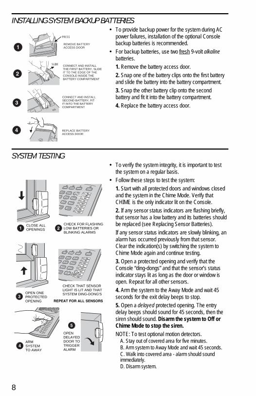
INSTALLING SYSTEM BACKUP BATTERIES• To provide backup power for the system during AC
power failures, installation of the optional Consolebackup batteries is recommended.
• For backup batteries, use two fresh 9-volt alkalinebatteries.1. Remove the battery access door.2. Snap one of the battery clips onto the first batteryand slide the battery into the battery compartment.3. Snap the other battery clip onto the secondbattery and fit it into the battery compartment.4. Replace the battery access door.
SYSTEM TESTING• To verify the system integrity, it is important to test
the system on a regular basis.• Follow these steps to test the system:
1. Start with all protected doors and windows closedand the system in the Chime Mode. Verify thatCHIME is the only indicator lit on the Console.2. If any sensor status indicators are flashing briefly,that sensor has a low battery and its batteries shouldbe replaced (see Replacing Sensor Batteries).If any sensor status indicators are slowly blinking, analarm has occurred previously from that sensor.Clear the indication(s) by switching the system toChime Mode again and continue testing.3. Open a protected opening and verify that theConsole “ding-dongs” and that the sensor’s statusindicator stays lit as long as the door or window isopen. Repeat for all other sensors.4. Arm the system to the Away Mode and wait 45seconds for the exit delay beeps to stop.5. Open a delayed protected opening. The entrydelay beeps should sound for 45 seconds, then thesiren should sound. Disarm the system to Off orChime Mode to stop the siren.NOTE: To test optional motion detectors.
A. Stay out of covered area for five minutes.B. Arm system to Away Mode and wait 45 seconds.C. Walk into covered area - alarm should soundimmediately.D. Disarm system.
10 OF 16
CLOSE ALLOPENINGS
CHECK FOR FLASHINGLOW BATTERIES ORBLINKING ALARMS
OPEN ONEPROTECTEDOPENING
CHECK THAT SENSORLIGHT IS LIT AND THATSYSTEM DING-DONG'S
ARMSYSTEMTO AWAY
OPENDELAYEDDOOR TOTRIGGERALARM
REMOVE BATTERYACCESS DOOR
CONNECT AND INSTALLTHE FIRST BATTERY, SLIDEIT TO THE EDGE OF THECONSOLE INSIDE THEBATTERY COMPARTMENT
CONNECT AND INSTALLSECOND BATTERY, FITIT INTO THE BATTERYCOMPARTMENT
REPLACE BATTERYACCESS DOOR
PRESS
SLIDE
INS
TR
, IN
ST
ALL
AT
ION
, SS
D8
Line
ar P
/N: 2
1558
3 B
Mat
eria
l: 20
# W
hite
Mea
d B
ond
with
80#
Whi
te C
oate
d C
over
Ink:
Bla
ckS
ize:
8.5
00"
x 5.
500"
Sca
le: 1
-1
8

CONNECTING AN EXTERNAL SPEAKER• One optional external speaker can be used with the
Console.• The external speaker will sound the sirens and all of
the advisory tones.• To install an external speaker:
1. Mount the speaker as described in its installationinstructions. Route the speaker wiring to the Console.2. Remove the battery door.3. Route the speaker wire through the wiring accessslot and connect each lead to the speaker connectorterminals with a small flat blade screwdriver.4. Replace the battery door.5. Arm the system and trigger an alarm, verify thatthe external speaker sounds the alarm siren and theadvisory tones.
CONNECTING A VOICE DIALER• The Console can be connected to a telephone Voice
Dialer.• A Voice Dialer will call a pre-programmed telephone
number if an alarm occurs and play your customrecorded message to the answering party.
• For information on purchasing a telephone VoiceDialer, contact a technical representative at thetelephone number listed on the warranty cardincluded with this product.1. Follow the Voice Dialer installation instructions toconnect its telephone wiring. Route the dialer inputwire to the Console.2. Plug the dialer input connector into the dialer jackon the bottom of the Console.3. After programming the dialer, arm the system andtrigger an alarm, verify that the Voice Dialer correctlycompletes the call and plays the message. After theVoice Dialer completes its telephone call, call thereceiving party and verify that the message wascorrectly sent.
11 OF 16
PHONE
DIALER INPUTWIRE
VOICEDIALER
ARM SYSTEMTO AWAY
OPENDOOR TOTRIGGERALARM
PLUG DIALERCONNECTORINTO CONSOLEJACK
ROUTE TOCONSOLE
TEST SPEAKER
MOUNTSPEAKERAND ROUTEWIRE TOCONSOLE
REMOVE BATTERYACCESS DOOR
PRESS
REPLACE BATTERYACCESS DOOR
CONNECT SPEAKERWIRES TO TERMINALS
INS
TR
, IN
ST
ALL
AT
ION
, SS
D8
Line
ar P
/N: 2
1558
3 B
Mat
eria
l: 20
# W
hite
Mea
d B
ond
with
80#
Whi
te C
oate
d C
over
Ink:
Bla
ckS
ize:
8.5
00"
x 5.
500"
Sca
le: 1
-1
9
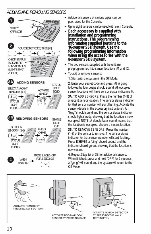
ADDING AND REMOVING SENSORS• Additional sensors of various types can be
purchased for the Console.• Up to eight sensors can be used with each Console.• Each accessory is supplied with
installation and programminginstructions. The programminginformation supplied pertains to the16-sensor SSD system. Use thefollowing programming informationwhen using the accessories with the8-sensor SSD8 system.
• The two sensors supplied with the unit arepre-programmed into sensor locations #1 and #2.
• To add or remove sensors:1. Start with the system in the Off Mode.2. Enter your secret code and press [#]. A gongfollowed by four beeps should sound. All occupiedsensor locations will have sensor status indicators lit.3A. TO ADD SENSORS: Press the number (1-8) ofa vacant sensor location. The sensor status indicatorfor that sensor number will start flashing. Activate thesensor (details in the accessory instructions). A“bing” should sound and the sensor status indicatorshould light steady, showing that the location is nowoccupied. NOTE: A double-buzz sound means thatthe location is occupied, choose a vacant location.3B. TO REMOVE SENSORS: Press the number(1-8) of the sensor to remove. The sensor statusindicator for that sensor number will start flashing.Press [CHIME], a “bing” should sound, and theindicator should go out, showing that the location isnow vacant.4. Repeat Step 3A or 3B for additional sensors.When finished, press and hold [OFF] for 2 seconds,a “gong” will sound and the system will return to theOff Mode.
12 OF 16
YOUR SECRET CODE, THEN [#]
def3
STATUSLIGHTBLINKS
def3
SELECT ASENSOR # (1-8)
STATUSLIGHTBLINKS
PRESSCHIME
STATUSLIGHTOUT
Chime
Off
WHENFINISHED
PRESS & HOLD [OFF]FOR 2 SECONDS
SELECTOFF MODE
CHECK STATUSINDICATORSFOR VACANCIES(LIGHTS THATARE OFF)
SELECT A VACANTSENSOR # (1-8) ACTIVATE
SENSOR
STATUSLIGHTSOLID
ACTIVATE REMOTE BYPRESSING LEFT BUTTON
ACTIVATE DOOR/WINDOWSENSOR BY PRESSING CASE
ACTIVATE MOTION DETECTORBY PRESSING THE WALK TEST BUTTON
INS
TR
, IN
ST
ALL
AT
ION
, SS
D8
Line
ar P
/N: 2
1558
3 B
Mat
eria
l: 20
# W
hite
Mea
d B
ond
with
80#
Whi
te C
oate
d C
over
Ink:
Bla
ckS
ize:
8.5
00"
x 5.
500"
Sca
le: 1
-1
10
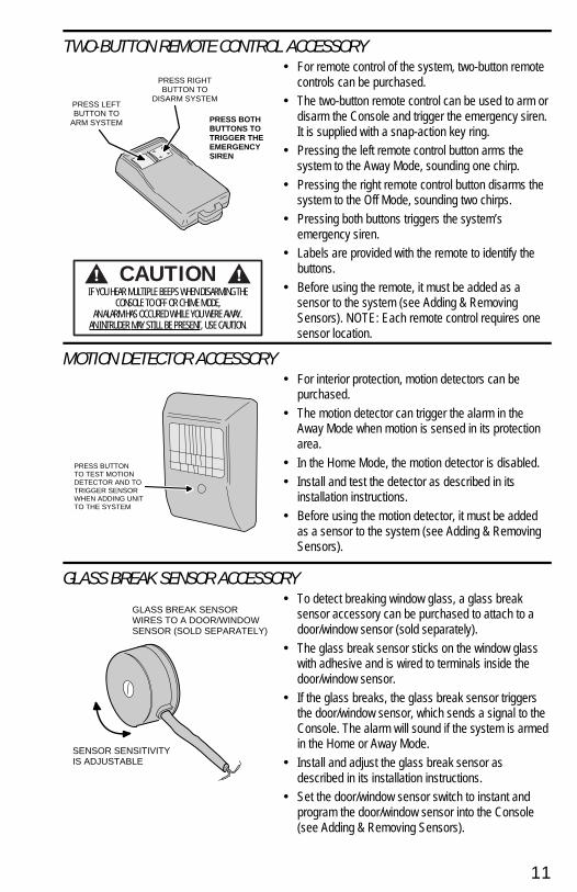
TWO-BUTTON REMOTE CONTROL ACCESSORY• For remote control of the system, two-button remote
controls can be purchased.• The two-button remote control can be used to arm or
disarm the Console and trigger the emergency siren.It is supplied with a snap-action key ring.
• Pressing the left remote control button arms thesystem to the Away Mode, sounding one chirp.
• Pressing the right remote control button disarms thesystem to the Off Mode, sounding two chirps.
• Pressing both buttons triggers the system’semergency siren.
• Labels are provided with the remote to identify thebuttons.
• Before using the remote, it must be added as asensor to the system (see Adding & RemovingSensors). NOTE: Each remote control requires onesensor location.
MOTION DETECTOR ACCESSORY• For interior protection, motion detectors can be
purchased.• The motion detector can trigger the alarm in the
Away Mode when motion is sensed in its protectionarea.
• In the Home Mode, the motion detector is disabled.• Install and test the detector as described in its
installation instructions.• Before using the motion detector, it must be added
as a sensor to the system (see Adding & RemovingSensors).
GLASS BREAK SENSOR ACCESSORY• To detect breaking window glass, a glass break
sensor accessory can be purchased to attach to adoor/window sensor (sold separately).
• The glass break sensor sticks on the window glasswith adhesive and is wired to terminals inside thedoor/window sensor.
• If the glass breaks, the glass break sensor triggersthe door/window sensor, which sends a signal to theConsole. The alarm will sound if the system is armedin the Home or Away Mode.
• Install and adjust the glass break sensor asdescribed in its installation instructions.
• Set the door/window sensor switch to instant andprogram the door/window sensor into the Console(see Adding & Removing Sensors).
13 OF 16
PRESS LEFTBUTTON TO
ARM SYSTEM
PRESS RIGHTBUTTON TO
DISARM SYSTEM
PRESS BOTHBUTTONS TOTRIGGER THEEMERGENCYSIREN
PRESS BUTTONTO TEST MOTIONDETECTOR AND TOTRIGGER SENSORWHEN ADDING UNITTO THE SYSTEM
GLASS BREAK SENSORWIRES TO A DOOR/WINDOWSENSOR (SOLD SEPARATELY)
SENSOR SENSITIVITYIS ADJUSTABLE
CAUTIONIF YOU HEAR MULTIPLE BEEPS WHEN DISARMING THE
CONSOLE TO OFF OR CHIME MODE,AN ALARM HAS OCCURED WHILE YOU WERE AWAY.
AN INTRUDER MAY STILL BE PRESENT, USE CAUTION.
INS
TR
, IN
ST
ALL
AT
ION
, SS
D8
Line
ar P
/N: 2
1558
3 B
Mat
eria
l: 20
# W
hite
Mea
d B
ond
with
80#
Whi
te C
oate
d C
over
Ink:
Bla
ckS
ize:
8.5
00"
x 5.
500"
Sca
le: 1
-1
11

MAGNETIC SWITCH ACCESSORY• External magnetic switches can be purchased and
wired to door/window sensors for additionalprotection.
• The external switch can be used with, or instead of,the door/window sensor’s internal switch to protectnearby openings.
• Install, wire and test the magnetic switch asdescribed in its installation instructions.
REPLACING SENSOR BATTERIES• Each wireless sensor is powered by batteries. When
the battery(s) get low, the sensor’s status indicatoron the Console will briefly flash.
• See the figure for details on replacing thedoor/window sensor batteries.
• Each accessory sensor’s instructions show detailsfor battery replacement.
CHANGING YOUR SECRET CODE• Your secret code can be one to five digits long (for
security at least 3 digits are recommended). Tochange your secret code follow these steps.1. Start with the system in the Off Mode.2. Enter your current secret code and press [#]. Agong followed by four beeps should sound.3. Press [9] then [HOME].4. Enter your new secret code (1 to 5 digits long) andpress [AWAY]. One Gong should sound.5. Press and hold [OFF] for two seconds to exitprogramming and return to Off Mode.
14 OF 16
EXTERNAL MAGNETIC SWITCHES CAN BE USED WITH DOOR/WINDOW SENSORS
WIRES CONNECT TOTERMINALS INSIDEDOOR/WINDOW SENSOR
+-
+-
INSTALL TWOTYPE 2032BATTERIES (+)SIDE UP
WHEN THE SYSTEM INDICATESA SENSOR LOW BATTERY, OPENSENSOR CASE AND REPLACESENSOR BATTERIES
GENTLY LIFT BATTERY CLAMP
Off
9 wxy
Home
Away
Off
START WITH THE SYSTEMIN THE OFF MODE
ENTER YOUR SECRET CODE
PRESS [#], ONE GONG ANDFOUR BEEPS SHOULD SOUND
PRESS [AWAY} ONE GONGSHOULD SOUND
ENTER YOUR NEW SECRET CODE(1 - 5 DIGITS LONG)
PRESS & HOLD [OFF] FOR TWOSECONDS TO FINISH
PRESS [9] THEN [HOME]
INS
TR
, IN
ST
ALL
AT
ION
, SS
D8
Line
ar P
/N: 2
1558
3 B
Mat
eria
l: 20
# W
hite
Mea
d B
ond
with
80#
Whi
te C
oate
d C
over
Ink:
Bla
ckS
ize:
8.5
00"
x 5.
500"
Sca
le: 1
-1
12

RESETTING THE CONSOLE• If you forget your secret code the Console can be
reset.➤ NOTE: Resetting the Console will erase all of the
wireless sensors and the secret code from thesystem’s memory. After resetting, each sensor willneed to be added back into the system.
• To reset the Console:1. Disconnect the 9-volt backup batteries (if installed).2. Unplug the AC adapter.3. Press and hold the [OFF] and [∗] keys whileplugging in the AC adapter. A beep will sound andthe system will assume the Off Mode.4. Create your secret code (see Apply Power &Create Your Secret Code) and re-program each ofthe wireless sensors (see Adding and RemovingSensors).
FCC NOTES• Radio controls provide a reliable communications link and fill an important need in portable wireless
signalling. However, there are some limitations which must be observed.✦ For U.S. installations only: The radios are required to comply with FCC Rules and Regulations
as Part 15 devices. As such, they have limited transmitter power and therefore limited range.✦ A receiver cannot respond to more than one transmitted signal at a time and may be blocked
by radio signals that occur on or near their operating frequencies, regardless of code settings. ✦ Changes or modifications to the device may void FCC compliance.✦ Infrequently used radio links should be tested regularly to protect against undetected
interference or fault.✦ A general knowledge of radio and its vagaries should be gained prior to acting as a wholesale
distributor or dealer, and these facts should be communicated to the ultimate users.• This equipment generates and uses radio frequency energy and if not installed and used properly,
that is, in strict accordance with the manufacturer’s instructions, may cause interference to radio andtelevision reception. It has been type tested and found to comply with the limits for a Class B digitaldevice in accordance with Part 15 of FCC Rules, which are designed to provide reasonableprotection against such interference in a residential installation. However, there is no guarantee thatinterference will not occur in a particular installation. If this equipment does cause interference toradio or television reception, which can be determined by turning the equipment off and on, the useris encouraged to try to correct the interference by one or more of the following measures:
✦ Relocate the Console away from the TV/radio receiver.✦ Plug the Console into a different wall outlet so that the Console is on a different branch circuit.✦ Re-orient the TV/radio antenna.✦ If necessary, the user should consult the dealer or an experienced radio/television technician
for additional suggestions.
INSIDE BACK COVER15 OF 16
DISCONNECT THEBACKUP BATTERIES(IF INSTALLED)
UN-PLUGAC ADAPTER
&
PRESS AND HOLD [OFF]AND [ ] WHILE PLUGGINGIN AC ADAPTER
INS
TR
, IN
ST
ALL
AT
ION
, SS
D8
Line
ar P
/N: 2
1558
3 B
Mat
eria
l: 20
# W
hite
Mea
d B
ond
with
80#
Whi
te C
oate
d C
over
Ink:
Bla
ckS
ize:
8.5
00"
x 5.
500"
Sca
le: 1
-1
13

Copyright © 1998 Linear Corporation
BACK COVER16 OF 16
INS
TR
, IN
ST
ALL
AT
ION
, SS
D8
Line
ar P
/N: 2
1558
3 B
Mat
eria
l: 20
# W
hite
Mea
d B
ond
with
80#
Whi
te C
oate
d C
over
Ink:
Bla
ckS
ize:
8.5
00"
x 5.
500"
Sca
le: 1
-1


