S82 W18717 Gemini Drive Muskego, Wisconsin 53150 Phone: (877) 622-2694 Fax: (888) 679-3319 www.nabcoentrances.com Technical Support: (866) 622-8325 Part #C-00169 Rev. 6/13/16 WARNING • Turn OFF all power to the Automac Door if a Safety System is not working. • Instruct the Owner to keep all power turned OFF unl correcve acon can be achieved by a NABCO trained technician. Failure to follow these pracces may result in serious consequences. • NEVER leave a Door operang without all Safety detecon systems operaonal. Wiring and Programming Manual ** with Opus Control** DN 1336 14 13 12 11 10 9 8 7 6 5 4 3 2 1
WARNING• Turn OFF all power to the Automatic Door if a Safety System is not working.
• Instruct the Owner to keep all power turned OFF until corrective action can be achieved by a NABCO trained technician. Failure to follow these practices may result in serious consequences.
• NEVER leave a Door operating without all Safety detection systems operational.
Wiring and Programming Manual ** with Opus Control**
DN 133614
1312
1110
98
76
54
32
1
THIS PAGE IS INTENTIONALLY LEFT BLANK
Rev. 6-13-16 Part #15-14973www.NabcoEntrances.com Opus Control Wiring and Programming Manual
Opus Control Wiring and Programming Manual www.NabcoEntrances.comPart #15-14973 Rev. 6-13-16
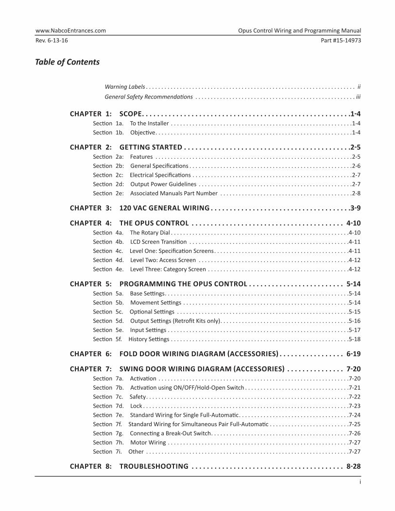
ii
WARNING LABELS
Warning labels are universal and used to alert an individual of potential harm to one’s self or to others. The following warning labels are listed in a hierarchy order that defines the most potential danger first, and the least potential danger last. Please refer to this page in the event that a warning label is displayed within this manual and further definition needs to be explained.
Indicates potentially dangerous situations. Danger is used when there is a hazardous situation where there is a high probability of severe injury or death. It should not be considered for property damage unless personal injury risk is present.
Indicates a hazardous situation which has some probability of severe injury. It should not be considered for property damage unless personal injury risk is present.
Indicates a hazardous situation which may result in a minor injury. Caution should not be used when there is a possibility of serious injury. Caution should not be considered for property damage accidents unless a personal injury risk is present.
Attention: A situation where material could be damaged or the function impaired.
Notice: Indicates a statement of company policy as the message relates to the personal safety or protection of property. Notice should not be used when there is a hazardous situation or personal risk.
Note: Indicates important information that provides further instruction.
Rev. 6-13-16 Part #15-14973www.NabcoEntrances.com Opus Control Wiring and Programming Manual
iii
GENERAL SAFETY RECOMMENDATIONS
Read, study and understand general safety recommendations, warning labels, installation and operating instructions contained in, or referenced in this manual before operating. If you do not understand the instruction, ask a qualified technician. Failure to do so may result in bodily injury, or property damage and will nullify all warranties.
Disconnect all power to the junction box prior to making any electrical connections. Failure to do so may result in seriouc personal or fatal injury. When uncertain whether power supply is disconnected, always verify using a voltmeter.
Notice: Wiring must meet all local, state, federal or other governing agency codes.
All electrical troublshooting or service must be performed by trained, qualified electrical technicians and comply with all applicable governing agency codes.
Do not place finger or uninsulated tools inside the electrical controller. Touching wires or other parts inside the enclosure may cause electrical shock, serious injury or death.
The Ground wire from the Opus Control 120 VAC Harness, and the Incoming 120 VAC Ground wire must be connected to the Ground screw located within the Swing door Header.
Do Not touch other parts of the Opus Control board with a screwdriver or anything else metal. Damage to electrical circuitry may occur.
If the door appears broken or does not seem to work correctly, it should be immediately removed from service until repairs can be carried out or a qualified service technician is contacted for corrective action.
Note: All Adjustments must be made with a small screwdriver. Do Not use a pencil.
Note: Final installation must conform to current versions of ANSI 156.19 for Low Energy Swingers or ANSI 156.10 for Full Automatic Swingers.
Note: Study and understand both ANSI Standard Codes A156.10 and A156.19.
Opus Control Wiring and Programming Manual www.NabcoEntrances.comPart #15-14973 Rev. 6-13-16
1-4 Scope
CHAPTER 1: Scope
Section 1a. To the Installer
The purpose of this manual is to familiarize the installer with the proper installation and operation of this system. It is essential that this equipment be properly installed and operational before the door is used by the public. It is the installer’s responsibility to inspect the operation of the entrance system to be sure it complies with any applicable standards. In the United States, ANSI Standard 156.10 (Used to cover Full Energy doors) and ANSI Standard 156.19 (Used to cover Low Energy doors) apply. Other local standards or codes may apply. Use them in addition to the ANSI standards.
The owner should determine the door is operating properly and should immediately call for service if there is any malfunction. All installation changes and adjustments must be made by qualified, NABCO trained technicians.
If after troubleshooting a problem, a satisfactory solution cannot be achieved, please call Nabco Entrances at 1-877-622-2694 between 8 am – 4:30 pm Central time for additional assistance.
Section 1b. Objective
The Opus Control is designed to be installed within the Header of: X New or Existing Swing Door systems.
X New or Existing Fold Door systems
X Existing Slide Door systems to replace Magnum Controls, Analog Controls, and U-01 to U-19 Controls. Sold as a Retrofit Kit only. Retrofit kits can be purchased by contacting Customer Service at 1-888-679-3319.
Rev. 6-13-16 Part #15-14973www.NabcoEntrances.com Opus Control Wiring and Programming Manual
Getting Started 2-5
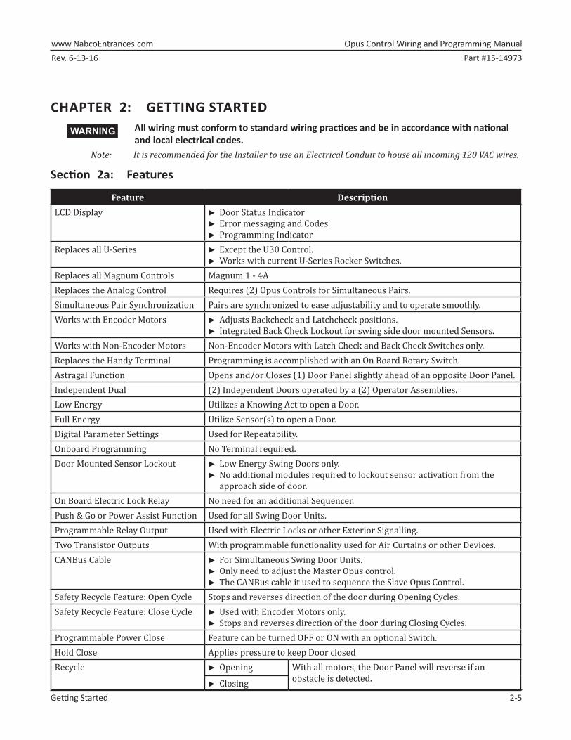
CHAPTER 2: GETTING STARTEDAll wiring must conform to standard wiring practices and be in accordance with national and local electrical codes.
Note: It is recommended for the Installer to use an Electrical Conduit to house all incoming 120 VAC wires.
Section 2a: Features
Feature DescriptionLCD Display ►► Door Status Indicator
►► Error messaging and Codes►► Programming Indicator
Replaces all U-Series ►► Except the U30 Control.►► Works with current U-Series Rocker Switches.
Replaces all Magnum Controls Magnum 1 - 4AReplaces the Analog Control Requires (2) Opus Controls for Simultaneous Pairs.Simultaneous Pair Synchronization Pairs are synchronized to ease adjustability and to operate smoothly.Works with Encoder Motors ►► Adjusts Backcheck and Latchcheck positions.
►► Integrated Back Check Lockout for swing side door mounted Sensors.Works with Non-Encoder Motors Non-Encoder Motors with Latch Check and Back Check Switches only.Replaces the Handy Terminal Programming is accomplished with an On Board Rotary Switch.Astragal Function Opens and/or Closes (1) Door Panel slightly ahead of an opposite Door Panel.Independent Dual (2) Independent Doors operated by a (2) Operator Assemblies.Low Energy Utilizes a Knowing Act to open a Door. Full Energy Utilize Sensor(s) to open a Door. Digital Parameter Settings Used for Repeatability.Onboard Programming No Terminal required.Door Mounted Sensor Lockout ►► Low Energy Swing Doors only.
►► No additional modules required to lockout sensor activation from the approach side of door.
On Board Electric Lock Relay No need for an additional Sequencer.Push & Go or Power Assist Function Used for all Swing Door Units.Programmable Relay Output Used with Electric Locks or other Exterior Signalling.Two Transistor Outputs With programmable functionality used for Air Curtains or other Devices.CANBus Cable ►► For Simultaneous Swing Door Units.
►► Only need to adjust the Master Opus control. ►► The CANBus cable it used to sequence the Slave Opus Control.
Safety Recycle Feature: Open Cycle Stops and reverses direction of the door during Opening Cycles. Safety Recycle Feature: Close Cycle ►► Used with Encoder Motors only.
►► Stops and reverses direction of the door during Closing Cycles.Programmable Power Close Feature can be turned OFF or ON with an optional Switch.Hold Close Applies pressure to keep Door closedRecycle ►► Opening With all motors, the Door Panel will reverse if an
Opus Control Wiring and Programming Manual www.NabcoEntrances.comPart #15-14973 Rev. 6-13-16
2-6 Getting Started
Section 2b: General Specifications
Specification DescriptionTemperature Range -13 degrees to 140 degrees FahrenheitMotor Type DC Brush Motor
DC Brush Motor (with Encoder installed on Gear Box)Motor Voltage 115VMotor Power Rating Long Frame (710 only): 55 W
Short Frame: 70 WPower Close Built-inMotor works with Encoder Motors In lieu of MicroswitchesMotor works with Microswitches In lieu of Encoder MotorsBack Check Angle Adjustment ►► 5 to 35 degrees from Full Open position
►► Used with Encoder Motor only.Latch Check Angle Adjustment ►► 10 to 40 degrees from Full Closed position
►► Used with Encoder Motor only.Door Movement Angle 30 degrees to 180 degreesBuilt In Sequencer Can activate:
►► Electric Locks►► Electric Strikes►► Electric Latch Retracted Panic Devices
Table 2-1 Modules
Module Part Number Function Power Source Current ConsumptionCP/RX Radio Control Receiver
24-11467 RF Signal Transmission 12 to 24 AC or DC 50mA (ea.unit) at 12VDC
Multi Module V-00144 Programmable Relay 12 to 24 AC or DC 40mA
Table 2-2 Input / Output Specifications
Input DescriptionNumber of Signal Inputs ►► 1 x Activation ►► 2 x Door Mode
►► 2 x Safety ►► 1 x Sequential►► 1 x Kill Signal ►► 2 x Programmable
Output DescriptionNumber of Outputs ►► 1 x Electric Lock Form C Relay
Rev. 6-13-16 Part #15-14973www.NabcoEntrances.com Opus Control Wiring and Programming Manual
Getting Started 2-7
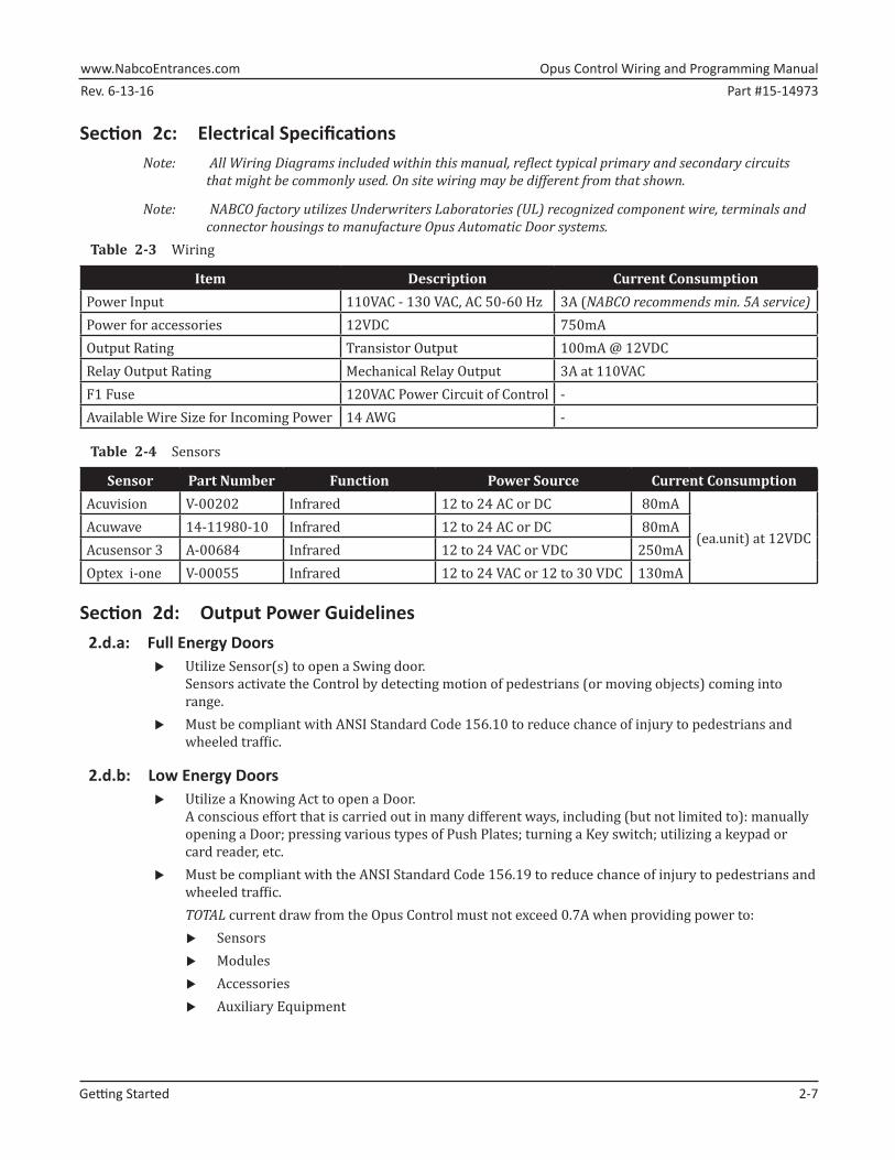
Section 2c: Electrical SpecificationsNote: All Wiring Diagrams included within this manual, reflect typical primary and secondary circuits
that might be commonly used. On site wiring may be different from that shown.
Note: NABCO factory utilizes Underwriters Laboratories (UL) recognized component wire, terminals and connector housings to manufacture Opus Automatic Door systems.
Table 2-3 Wiring
Item Description Current ConsumptionPower Input 110VAC - 130 VAC, AC 50-60 Hz 3A (NABCO recommends min. 5A service)Power for accessories 12VDC 750mA Output Rating Transistor Output 100mA @ 12VDCRelay Output Rating Mechanical Relay Output 3A at 110VACF1 Fuse 120VAC Power Circuit of Control -Available Wire Size for Incoming Power 14 AWG -
Table 2-4 Sensors
Sensor Part Number Function Power Source Current ConsumptionAcuvision V-00202 Infrared 12 to 24 AC or DC 80mA
(ea.unit) at 12VDCAcuwave 14-11980-10 Infrared 12 to 24 AC or DC 80mA Acusensor 3 A-00684 Infrared 12 to 24 VAC or VDC 250mAOptex i-one V-00055 Infrared 12 to 24 VAC or 12 to 30 VDC 130mA
Section 2d: Output Power Guidelines 2.d.a: Full Energy Doors
X Utilize Sensor(s) to open a Swing door. Sensors activate the Control by detecting motion of pedestrians (or moving objects) coming into range.
X Must be compliant with ANSI Standard Code 156.10 to reduce chance of injury to pedestrians and wheeled traffic.
2.d.b: Low Energy Doors X Utilize a Knowing Act to open a Door.
A conscious effort that is carried out in many different ways, including (but not limited to): manually opening a Door; pressing various types of Push Plates; turning a Key switch; utilizing a keypad or card reader, etc.
X Must be compliant with the ANSI Standard Code 156.19 to reduce chance of injury to pedestrians and wheeled traffic. TOTAL current draw from the Opus Control must not exceed 0.7A when providing power to:
X Sensors X Modules X Accessories X Auxiliary Equipment
Opus Control Wiring and Programming Manual www.NabcoEntrances.comPart #15-14973 Rev. 6-13-16
2-8 Getting Started
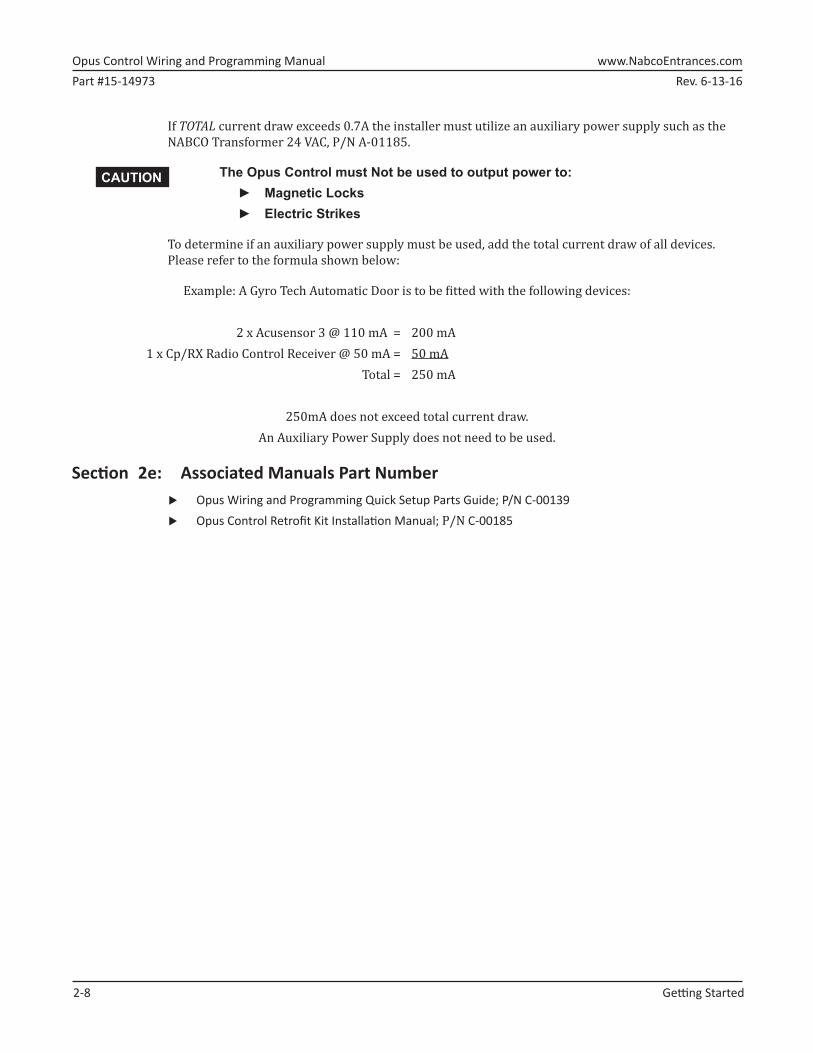
If TOTAL current draw exceeds 0.7A the installer must utilize an auxiliary power supply such as the NABCO Transformer 24 VAC, P/N A-01185.
The Opus Control must Not be used to output power to: ► Magnetic Locks ► Electric Strikes
To determine if an auxiliary power supply must be used, add the total current draw of all devices. Please refer to the formula shown below:
Example: A Gyro Tech Automatic Door is to be fitted with the following devices:
2 x Acusensor 3 @ 110 mA = 200 mA1 x Cp/RX Radio Control Receiver @ 50 mA = 50 mA
Total = 250 mA
250mA does not exceed total current draw. An Auxiliary Power Supply does not need to be used.
Section 2e: Associated Manuals Part Number X Opus Wiring and Programming Quick Setup Parts Guide; P/N C-00139 X Opus Control Retrofit Kit Installation Manual; P/N C-00185
Rev. 6-13-16 Part #15-14973www.NabcoEntrances.com Opus Control Wiring & Programming Manual
120 VAC General Wiring 3-9
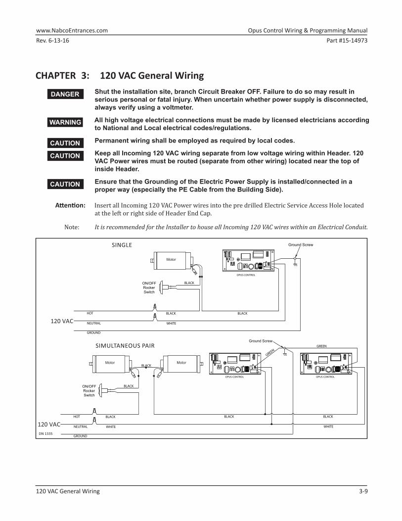
CHAPTER 3: 120 VAC General WiringShut the installation site, branch Circuit Breaker OFF. Failure to do so may result in serious personal or fatal injury. When uncertain whether power supply is disconnected, always verify using a voltmeter.
All high voltage electrical connections must be made by licensed electricians according to National and Local electrical codes/regulations.
Permanent wiring shall be employed as required by local codes.
Keep all Incoming 120 VAC wiring separate from low voltage wiring within Header. 120 VAC Power wires must be routed (separate from other wiring) located near the top of inside Header.
Ensure that the Grounding of the Electric Power Supply is installed/connected in a proper way (especially the PE Cable from the Building Side).
Attention: Insert all Incoming 120 VAC Power wires into the pre drilled Electric Service Access Hole located at the left or right side of Header End Cap.
Note: It is recommended for the Installer to house all Incoming 120 VAC wires within an Electrical Conduit.
Opus Control Wiring and Programming Manual www.NabcoEntrances.comPart #15-14973 Rev. 6-13-16
4-10 The Opus Control
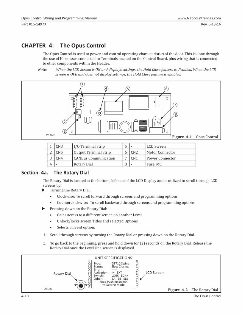
CHAPTER 4: The Opus ControlThe Opus Control is used to power and control operating characteristics of the door. This is done through the use of Harnesses connected to Terminals located on the Control Board, plus wiring that is connected to other components within the Header.
Note: When the LCD Screen is ON and displays settings, the Hold Close feature is disabled. When the LCD screen is OFF, and does not display settings, the Hold Close feature is enabled.
Figure 4-1 Opus ControlDN 1328
1413
1211
109
8
76
54
32
1
①
②
③
④ ⑤ ⑥
⑦
⑧
1 CN3 I/O Terminal Strip 5 - LCD Screen2 CN5 Output Terminal Strip 6 CN2 Motor Connector3 CN4 CANBus Communication 7 CN1 Power Connector4 - Rotary Dial 8 - Fuse, MC
Section 4a. The Rotary DialThe Rotary Dial is located at the bottom, left side of the LCD Display and is utilized to scroll through LCD screens by:
X Turning the Rotary Dial:• Clockwise: To scroll forward through screens and programming options. • Counterclockwise: To scroll backward through screens and programming options.
X Pressing down on the Rotary Dial: • Gains access to a different screen on another Level.• Unlock/locks screen Titles and selected Options.• Selects current option.
1. Scroll through screens by turning the Rotary Dial or pressing down on the Rotary Dial.
2. To go back to the beginning, press and hold down for (2) seconds on the Rotary Dial. Release the Rotary Dial once the Level One screen is displayed.
DN 1242
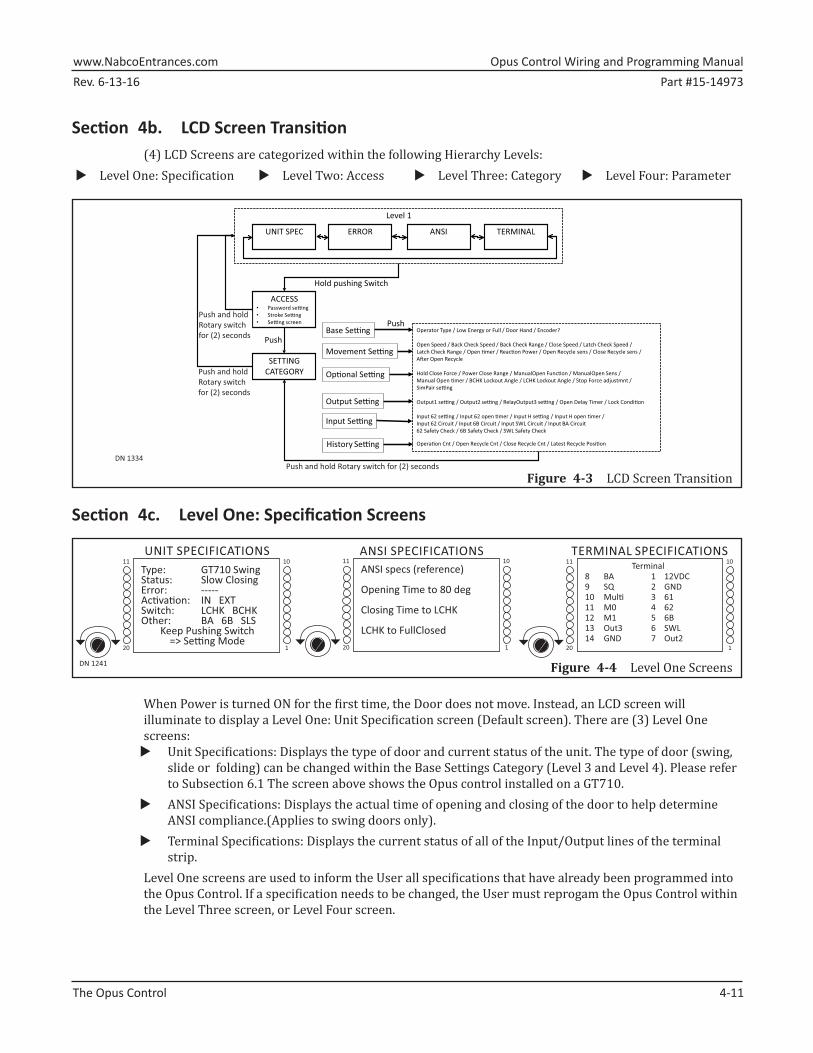
Type: GT710 SwingStatus: Slow ClosingError: -----Ac� va� on: IN EXTSwitch: LCHK BCHKOther: BA 6B SLS
Operator Type / Low Energy or Full / Door Hand / Encoder?
Open Speed / Back Check Speed / Back Check Range / Close Speed / Latch Check Speed / Latch Check Range / Open �mer / Reac�on Power / Open Recycle sens / Close Recycle sens / A�er Open Recycle
Hold Close Force / Power Close Range / ManualOpen Func�on / ManualOpen Sens / Manual Open �mer / BCHK Lockout Angle / LCHK Lockout Angle / Stop Force adjustmnt / SimPair se�ng
When Power is turned ON for the first time, the Door does not move. Instead, an LCD screen will illuminate to display a Level One: Unit Specification screen (Default screen). There are (3) Level One screens:
X Unit Specifications: Displays the type of door and current status of the unit. The type of door (swing, slide or folding) can be changed within the Base Settings Category (Level 3 and Level 4). Please refer to Subsection 6.1 The screen above shows the Opus control installed on a GT710.
X ANSI Specifications: Displays the actual time of opening and closing of the door to help determine ANSI compliance.(Applies to swing doors only).
X Terminal Specifications: Displays the current status of all of the Input/Output lines of the terminal strip.
Level One screens are used to inform the User all specifications that have already been programmed into the Opus Control. If a specification needs to be changed, the User must reprogam the Opus Control within the Level Three screen, or Level Four screen.
Opus Control Wiring and Programming Manual www.NabcoEntrances.comPart #15-14973 Rev. 6-13-16
4-12 The Opus Control
Section 4d. Level Two: Access Screen
DN 1244
Password Password
Stroke Learning Yes No
ACCESS SCREEN11
20
10
1
Figure 4-5 Level Two Screen
4.d.a PasswordThe Default password is (0045) and has been programmed into all Opus Controls. To prevent tampering of the Opus Control, the password cannot be changed.
1. Briefly press down on the Rotary Dial. Turn the Rotary dial until the first number (0) is displayed. Repeat until the Default password (0045) has been entered. a. Level Three screen will display.
4.d.b Stroke Learning X Activates the Door to teach the Opus Control the Full Open and Full Closed positions. X Measures from Full Closed to Full Open points to determine where Check Points should happen. X Determines if an existing Operator Type is correct. X Determines if Handing is correct.
1. Briefly press down on the Rotary Dial to select:
X Yes• Opus will start the Stroke Learning Cycle• The door will Close slowly → Open Slowly → Close Again
X No• If the Operator and Door Handing settings are correct, Opus will not have to Learn Stroke.
Opus automatically determines the Stroke during a normal door cycle.• If the Operator Type or Door Hand are the wrong setting, the following messages after the
Stroke Learning Cycle will display: “Wrong Motor! Restroke”; or “Wrong Hand! Restroke”. If this event occurs, enter the proper settings within the Base Setting Category screens.
Section 4e. Level Three: Category Screen 4.e.a Within Password
Level Three Setting Category displays Parameter options for Level Four.
Rev. 6-13-16 Part #15-14973www.NabcoEntrances.com Opus Control Wiring and Programming Manual
The Opus Control 4-13
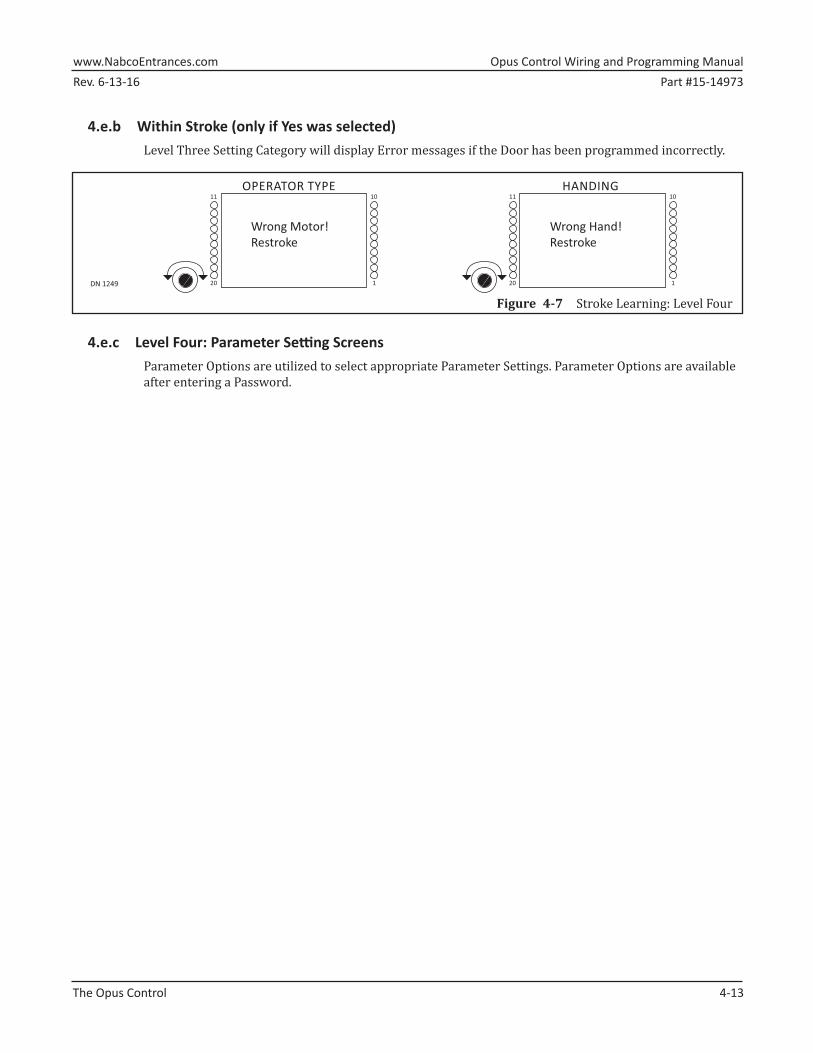
4.e.b Within Stroke (only if Yes was selected)Level Three Setting Category will display Error messages if the Door has been programmed incorrectly.
Wrong Motor! Restroke
DN 1249
11
20
10
1
OPERATOR TYPE
Wrong Hand! Restroke
11
20
10
1
HANDING
Figure 4-7 Stroke Learning: Level Four
4.e.c Level Four: Parameter Setting ScreensParameter Options are utilized to select appropriate Parameter Settings. Parameter Options are available after entering a Password.
Opus Control Wiring and Programming Manual www.NabcoEntrances.comPart #15-14973 Rev. 6-13-16
5-14 Programming the Opus Control
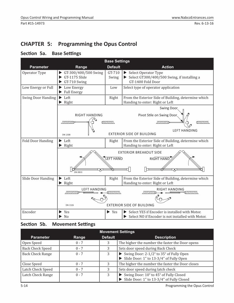
CHAPTER 5: Programming the Opus ControlSection 5a. Base Settings
Base SettingsParameter Range Default Action
Operator Type ►X GT-300/400/500 Swing►X GT-1175 Slide►X GT-710 Swing
GT-710Swing
►X Select Operator Type►X Select GT300/400/500 Swing, if installing a
GT-1400 Fold DoorLow Energy or Full ►X Low Energy
►X Full Energy Low Select type of operator application
Swing Door Handing ►X Left►X Right
Right From the Exterior Side of Building, determine which Handing to enter: Right or Left
RIGHT HANDING
DN 1308
LEFT HANDING
Pivot S� le on Swing Door
Swing Door
EXTERIOR SIDE OF BUILDING
Fold Door Handing ►X Left►X Right
Right From the Exterior Side of Building, determine which Handing to enter: Right or Left
DN 0833
EXTERIOR BREAKOUT SIDE
LEFT HAND RIGHT HAND
Slide Door Handing ►X Left►X Right
Right From the Exterior Side of Building, determine which Handing to enter: Right or Left
RIGHT HANDING
DN 1326
LEFT HANDING
EXTERIOR SIDE OF BUILDING
Encoder ►X Yes►X No
►X Yes ►X Select YES if Encoder is installed with Motor.►X Select NO if Encoder is not installed with Motor.
Section 5b. Movement SettingsMovement Settings
Parameter Range Default DescriptionOpen Speed 0 - 7 3 The higher the number the faster the Door opensBack Check Speed 0 - 7 3 Sets door speed during Back CheckBack Check Range 0 - 7 3 ►X Swing Door: 2-1/2° to 35° of Fully Open
►X Slide Door: 1" to 13-3/4" of Fully OpenClose Speed 0 - 7 3 The higher the number the faster the Door closesLatch Check Speed 0 - 7 3 Sets door speed during latch checkLatch Check Range 0 - 7 3 ►X Swing Door: 10° to 45° of Fully Closed
Rev. 6-13-16 Part #15-14973www.NabcoEntrances.com Opus Control Wiring and Programming Manual
Programming the Opus Control 5-15
Movement SettingsParameter Range Default Description
Open Timer 0-10, 12, 15, 20, 25, 30 2 Amount of Hold Open time after deactivation in secondsReaction Power 0 - 7 3 Determines how fast the door reacts to a reactivation
when closingOpen Recycle Sens 0 - 7 3 Determines how hard the door will push against an
obstruction during openingClose Recycle Sens 0 - 7 3 Determines how hard the door will push against an
obstruction during closingAfter Open Recycle Slow Open Stop Slow
OpenDetermines what happens after a recycle during Opening Recycle
Close Recycle Reopen Yes Yes Determines what happens after a recycle during Closing CycleNo
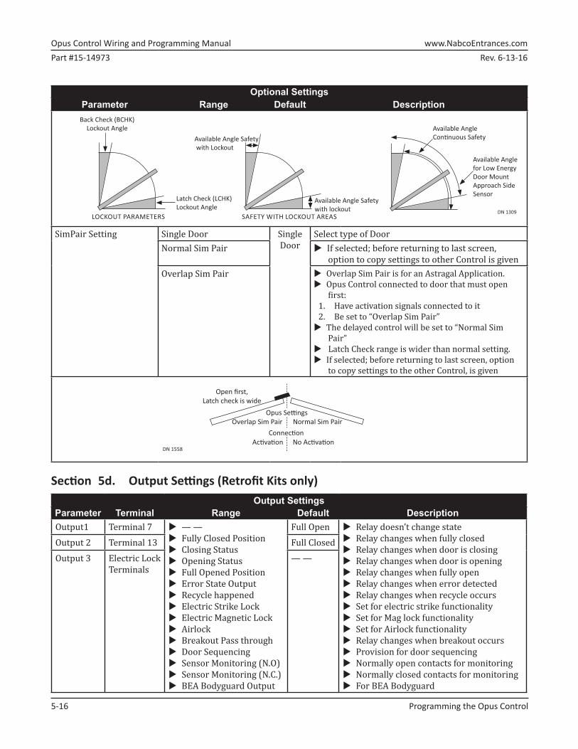
Section 5c. Optional SettingsOptional Settings
Parameter Range Default DescriptionHold Close Force 0 - 3 0 0 OFF
3 Strongest Hold Close forcePower Close Range ►X No Power Close
►X Whole Close Cycle►X Latch Check Only►X Latch and Back
No Power Close
Closing assisted by Motor to fight wind or stack pressure
Manual Open Function No Action No Action
Does nothingPush and Go P & G Enables push and goStop and Close S & C Door pauses at open angle then closesOpen Assist ►X Assisted Power from motor when door is pushed
►X Depends on how strong door is pushed►X Power always within range “Open recycle
sensitivity” setting►X Door will stop during the event that the door is
not pushedManual Open Sensitivity 0 - 3 1 Angle/force to activate Push and GoManual Open Timer ►X 0-10, 12, 15, 20, 25, 30
►X Same as Open Timer4 Hold Open time for Manual Opening
Stop Force Adjustment 0 - 7 3 Determines how the door reacts to a continuoussafety signal: Slow Open, Stop, or Slow Close
BCHK Lockout Angle 0 - 9 0 ►X Sensor lockout angle at Back Check►X Range is from 0° to 30° from Fully Open►X Used for Swing or Fold Door Units only
A
0 Narrow A Wide
LCHK Lockout Angle 0 - 9 0 ►X Sensor lockout angle at Latch Check►X Range is from 0° to 30° from Fully Close►X Used for Swing or Fold Door Units only
Parameter Terminal Range Default DescriptionOutput1 Terminal 7 ►X — —
►X Fully Closed Position►X Closing Status►X Opening Status►X Full Opened Position►X Error State Output►X Recycle happened►X Electric Strike Lock►X Electric Magnetic Lock►X Airlock►X Breakout Pass through►X Door Sequencing►X Sensor Monitoring (N.O) ►X Sensor Monitoring (N.C.)►X BEA Bodyguard Output
Full Open ►X Relay doesn’t change state►X Relay changes when fully closed►X Relay changes when door is closing►X Relay changes when door is opening►X Relay changes when fully open►X Relay changes when error detected►X Relay changes when recycle occurs►X Set for electric strike functionality►X Set for Mag lock functionality►X Set for Airlock functionality►X Relay changes when breakout occurs►X Provision for door sequencing►X Normally open contacts for monitoring►X Normally closed contacts for monitoring►X For BEA Bodyguard
Output 2 Terminal 13 Full ClosedOutput 3 Electric Lock
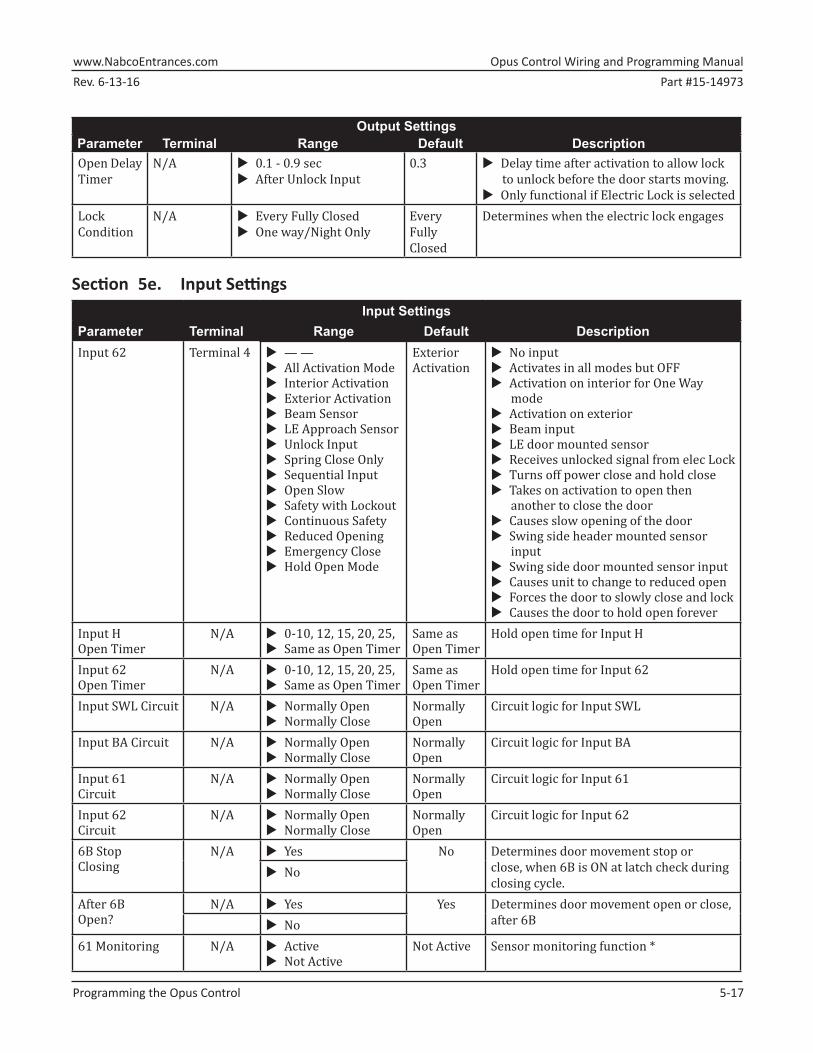
►X All Activation Mode►X Interior Activation►X Exterior Activation►X Beam Sensor►X LE Approach Sensor►X Unlock Input►X Spring Close Only►X Sequential Input►X Open Slow►X Safety with Lockout►X Continuous Safety►X Reduced Opening►X Emergency Close►X Hold Open Mode
Exterior Activation
►X No input►X Activates in all modes but OFF►X Activation on interior for One Way
mode►X Activation on exterior►X Beam input►X LE door mounted sensor►X Receives unlocked signal from elec Lock►X Turns off power close and hold close►X Takes on activation to open then
another to close the door►X Causes slow opening of the door►X Swing side header mounted sensor
input►X Swing side door mounted sensor input►X Causes unit to change to reduced open►X Forces the door to slowly close and lock►X Causes the door to hold open forever
Input H Open Timer
N/A ►X 0-10, 12, 15, 20, 25,►X Same as Open Timer
Same asOpen Timer
Hold open time for Input H
Input 62Open Timer
N/A ►X 0-10, 12, 15, 20, 25,►X Same as Open Timer
Same as Open Timer
Hold open time for Input 62
Input SWL Circuit N/A ►X Normally Open►X Normally Close
NormallyOpen
Circuit logic for Input SWL
Input BA Circuit N/A ►X Normally Open►X Normally Close
NormallyOpen
Circuit logic for Input BA
Input 61 Circuit
N/A ►X Normally Open►X Normally Close
NormallyOpen
Circuit logic for Input 61
Input 62 Circuit
N/A ►X Normally Open►X Normally Close
NormallyOpen
Circuit logic for Input 62
6B StopClosing
N/A ►X Yes No Determines door movement stop or close, when 6B is ON at latch check during closing cycle.
►X No
After 6BOpen?
N/A ►X Yes Yes Determines door movement open or close, after 6B►X No
Opus Control Wiring and Programming Manual www.NabcoEntrances.comPart #15-14973 Rev. 6-13-16
5-18 Programming the Opus Control
Input SettingsParameter Terminal Range Default Description62 Monitoring N/A ►X Active
►X Not ActiveNot Active Sensor monitoring function *
6B Monitoring N/A ►X Active►X Not Active
Not Active Sensor monitoring function *
SWL Monitoring N/A ►X Active►X Not Active
Not Active Sensor monitoring function *
* If Safety Check is enabled for any input then the sensor MUST be connected to Output 1 or 2.Output 1 or 2 must then be programmed to “Sensor Health Check”. If an error occurs, the door will
hold open until the error clears or the power is cycled.
Section 5f. History SettingsHistory Settings
Parameter DescriptionOperation Cnt ►X Indicates number of Door open cycles.
►X Updated every 100 door cycles.Open Recycle Cnt Indicates number of times the Door reversed direction during Opening cycle after sensing:
►X An object was struck.►X The amount of friction that surpassed the recycle sensitivity setting.
Close Recycle Cnt Indicates number of times the Door reversed direction during Closing cycle after sensing:►X An object was struck.►X The amount of friction that surpassed the Recycle Sensitivity Setting.
Latest Recycle Position ►X Indicates the last recycle position during opening and closing.►X For swing doors it displays the approximate angle from closed at recycle. For slide
doors it displays the position in inches from closed.
Opus Control Wiring & Programming Manual www.NabcoEntrances.comPart #15-14973 Rev. 6-13-16
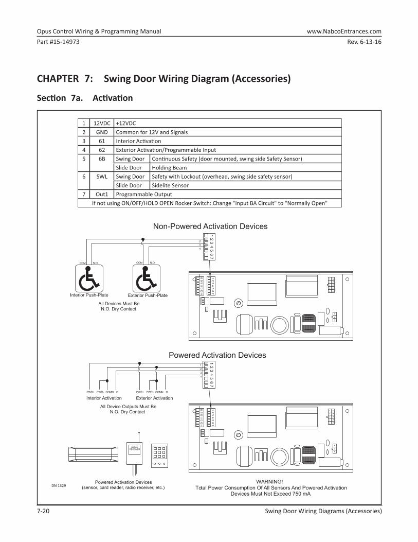
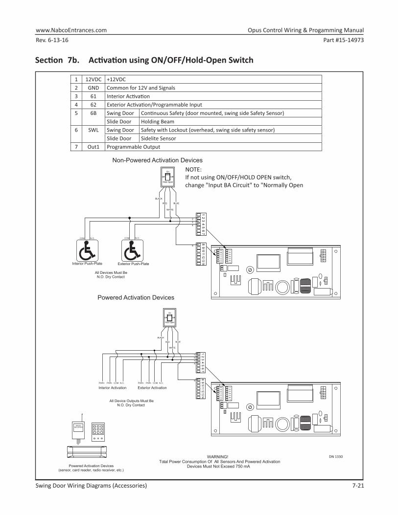
7-26 Swing Door Wiring Diagrams (Accessories)
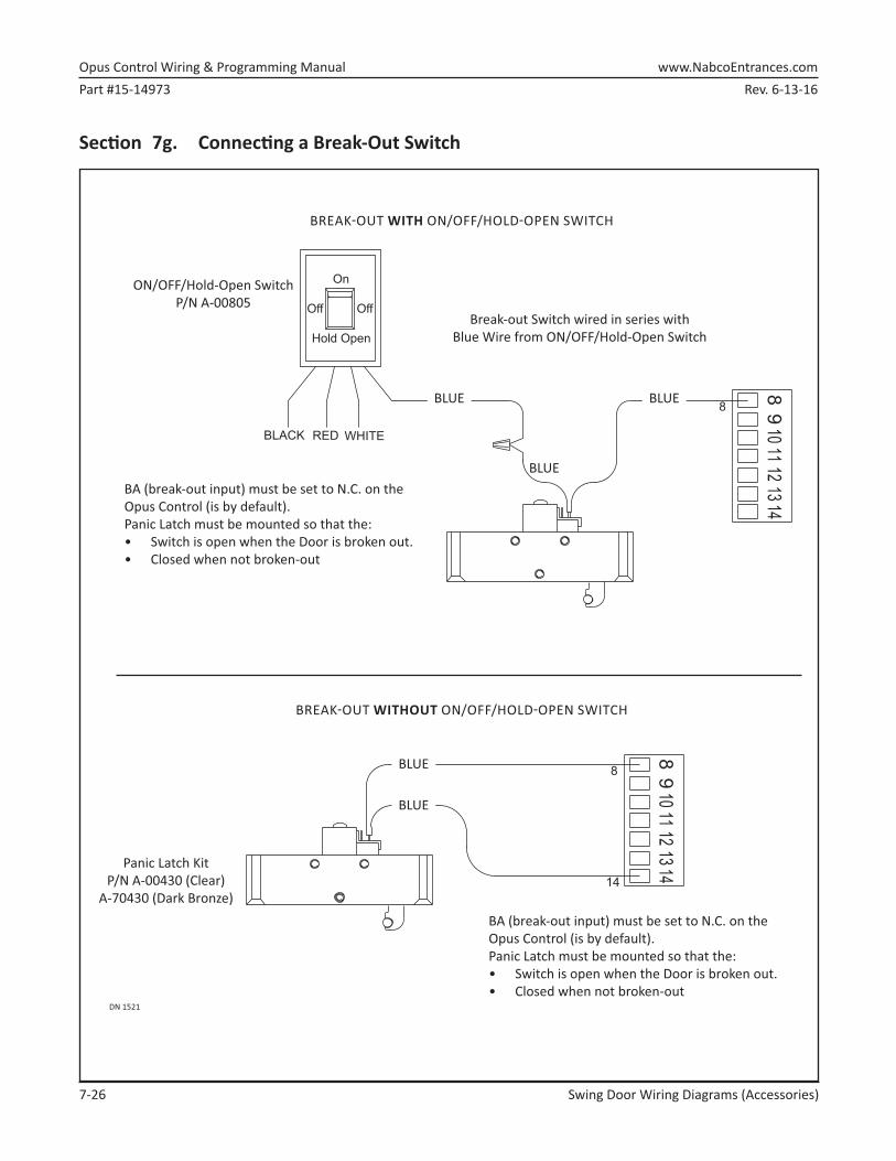
Section 7g. Connecting a Break-Out Switch
DN 1521
BREAK�OUT WITH ON/OFF/HOLD�OPEN SWITCH
ON/OFF/Hold-Open SwitchP/N A-00805
Break-out Switch wired in series withBlue Wire from ON/OFF/Hold-Open Switch
Panic Latch Kit P/N A-00430 (Clear)
A-70430 (Dark Bronze)
REDBLACK
1413
1211
109
8
8
WHITE
Off
Hold Open
On
Off
1413
1211
109
8
8
14
BA (break-out input) must be set to N.C. on the Opus Control (is by default).Panic Latch must be mounted so that the:• Switch is open when the Door is broken out.• Closed when not broken-out
BREAK�OUT WITHOUT ON/OFF/HOLD�OPEN SWITCH
BA (break-out input) must be set to N.C. on the Opus Control (is by default).Panic Latch must be mounted so that the:• Switch is open when the Door is broken out.• Closed when not broken-out
Rev. 6-13-16 Part #15-14973www.NabcoEntrances.com Opus Control Wiring & Progamming Manual
Swing Door Wiring Diagrams (Accessories) 7-27
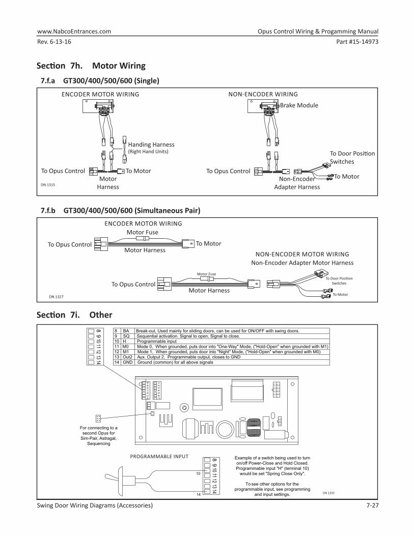
Section 7h. Motor Wiring 7.f.a GT300/400/500/600 (Single)
DN 1315
ENCODER MOTOR WIRING NON�ENCODER WIRING
Handing Harness (Right Hand Units)
To Opus Control To MotorTo MotorNon-Encoder
Adapter Harness
To Opus ControlMotor
Harness
To Door Posi� onSwitches
Brake Module
7.f.b GT300/400/500/600 (Simultaneous Pair)
DN 1327
ENCODER MOTOR WIRING
To Opus ControlMotor Harness
Motor Fuse
To Motor
NON�ENCODER MOTOR WIRINGNon-Encoder Adapter Motor Harness
To Door Posi� on Switches
To Motor
Motor Fuse
Motor HarnessTo Opus Control
Section 7i. Other
DN 1333
1413
1211
109
8
76
54
32
1
1413
1211
109
8
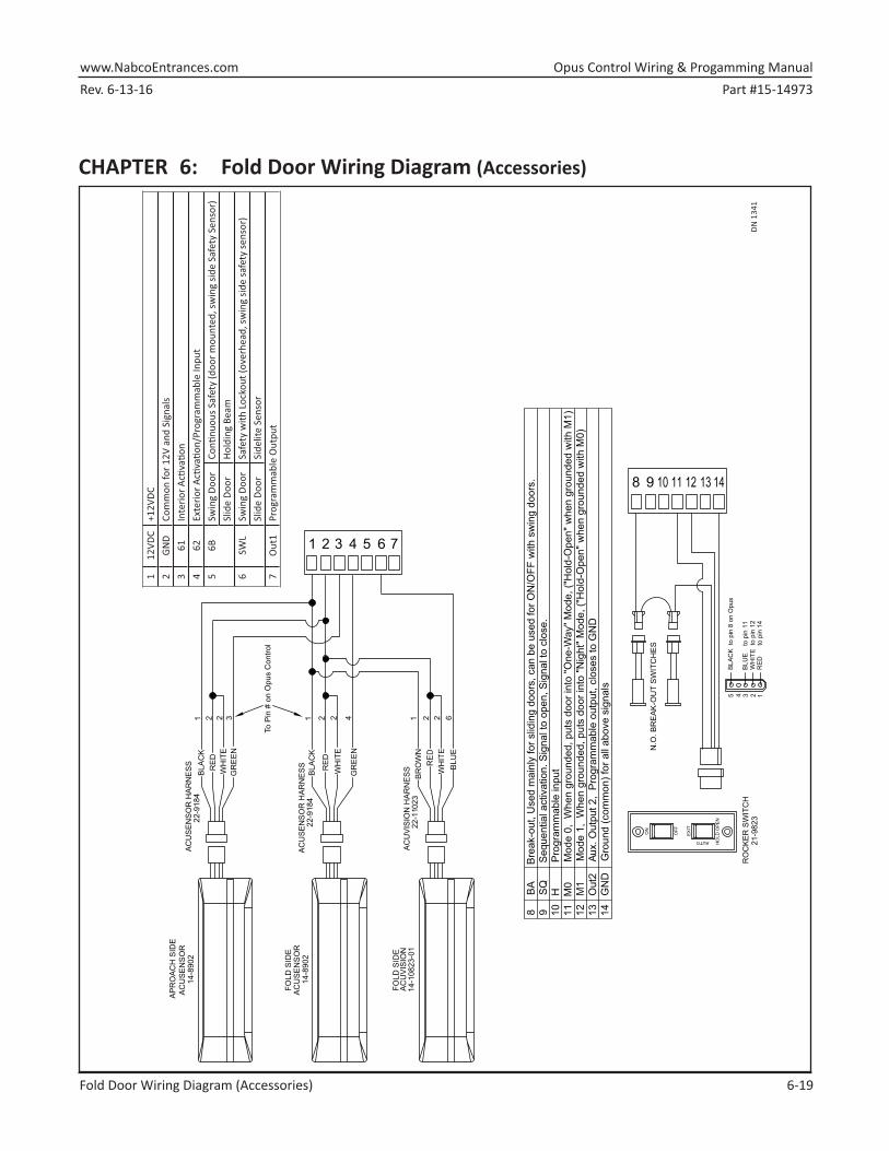
8 BA Break-out, Used mainly for sliding doors, can be used for ON/OFF with swing doors. 9 SQ Sequential activation. Signal to open, Signal to close.10 H Programmable input 11 M0 Mode 0, When grounded, puts door into "One-Way" Mode, ("Hold-Open" when grounded with M1)12 M1 Mode 1, When grounded, puts door into "Night" Mode, ("Hold-Open" when grounded with M0)13 Out2 Aux. Output 2, Programmable output, closes to GND14 GND Ground (common) for all above signals
For connecting to a second Opus for
Sim-Pair, Astragal, Sequencing
1413
1211
109
8
10
14
Example of a switch being used to turn on/off Power-Close and Hold Closed.Programmable input "H" (terminal 10)
would be set "Spring Close Only".
To see other options for the programmable input, see programming
Opus Control Wiring & Programming Manual www.NabcoEntrances.comPart #15-14973 Rev. 6-13-16
8-28 Troubleshooting
CHAPTER 8: TroubleshootingIf the Opus detects an error, the LCD backlight will start flashing and display an Error message within the Error Screen or before the Level Two Screen.
Table 1: Error Message
Error Msg Description ResolutionRecycle Warning Recycle was detected more than (5) times while
opening or closing cycle continuously. X Check Door resistance and Door
Path for resistance to movement.•►It may be necessary to adjust the
Recycle Sensitivity.MPU Error Microprocessor detects errors within the Internal
or External Circuits. X This could be a random error.
•►If the Error occurs repeatedly, please replace the Opus Control.
Drive Circuit Error If the Drive Circuit detects an unusual state, the Opus will stop door movement. Possible causes are:
X Over current at motor X Abnormal voltage at Motor Circuit X Abnormal value from Motor Current detection.
X Check the Motor connection. •►Opus Control may not be
connected to the motor. •►Motor wire may be shorted.
X If Motor connection is normal; the cause could be electrical noise.
X If this error doesn’t occur repeatedly then it’s most likely not an issue.
Communication Error X CAN-bus Communication Error X Can happen in Simultaneous Pair applications.
Check the CAN-bus Cable between thetwo Opus Controls.
61 Sensor Error X The Sensor must support active monitoring. X This error could occur when the sensors are
setup for Health Check through:•►Output 1,2 or 3•►Input 61, 62, 6B
X SWL is set for Safety Check and the sensor doesn’t respond to the safety check signal.
Turn the power off and then on to seeif the error clears. If not then check thewiring from the sensor to the Outputterminal. Possibly replace the sensor.
62 Sensor Error6B Sensor ErrorSWL Sensor Error
Notice: If after troubleshooting a problem, and a satisfactory solution cannot be achieved, please call Nabco Entrances at 1-877-622-2694 between 8 am – 4:30pm Central time for additional assistance.
DO NOT leave any problem unresolved. If the door cannot be repaired immediately, turn off the door and leave it inoperable until repairs can be made. Advise the owner NOT to operate the door in the automatic mode until repairs are effected. NEVER leave a door operating without all safety detection systems operational.


![Tristeza , la - Opus 22 - piano - solo - seul - [Opus 22 -] · Tristeza , la - Opus 22 - piano - solo - seul - [Opus 22 -] Author: stumpf, werner - Arranger: STUMPF Werner - Publisher:](https://static.documents.pub/doc/80x56/5fdeb08016d6b213e84f7eba/tristeza-la-opus-22-piano-solo-seul-opus-22-tristeza-la-opus.jpg)


