21
1 WIRING OUTLINE – CPU SYSTEM January, 2012 www.pipeorgancontrol.com

1
WIRING OUTLINE – CPU SYSTEM
January, 2012
www.pipeorgancontrol.com

2
TABLE OF CONTENTS
I. REQUIRED TOOLS ................................................................................................................................................................ 3
SMALL WATTAGE SOLERING IRON WITH PENCIL TIP ....................................................................................................................... 3 WIRE WRAP PENCIL ......................................................................................................................................................................... 3 MULTIMETER ................................................................................................................................................................................... 3 JUMPER CLIP LEAD ........................................................................................................................................................................... 3 PHONE ............................................................................................................................................................................................. 3 OSCILLOSCOPE ................................................................................................................................................................................. 3
II. PHYSICAL COMPONENTS ..................................................................................................................................................... 4
CPU CIRCUIT CARD .............................................................................................................................................................................. 4 INPUT CIRCUIT CARDS - 2 X 64 = 128 INPUTS ON EACH CARD ..................................................................................................................... 4 OUTPUT CIRCUIT CARDS - 2 X 64 = 128 OUTPUTS ON EACH CARD ............................................................................................................... 4 A TO D CIRCUIT CARD AND POTENTIOMETERS ............................................................................................................................................ 4 LCD ................................................................................................................................................................................................... 4 MIDI IN/THRU/OUT CONNECTOR CARD ............................................................................................................................................... 4 RIBBON CABLE ................................................................................................................................................................................. 4 FIBER OPTIC CABLES ......................................................................................................................................................................... 4
III. POWERS AND GROUNDS ..................................................................................................................................................... 7
110VAC CIRCUIT FOR POWER SUPPLY/RECTIFIER ............................................................................................................................ 7 110VAC CIRCUIT FOR BLOWER ........................................................................................................................................................ 7 ON/OFF SWITCH .............................................................................................................................................................................. 7 POWER SUPPLY CABLES ................................................................................................................................................................... 7
IV. INPUTS ............................................................................................................................................................................ 9
DEFINITION ...................................................................................................................................................................................... 9 WIRING HINTS .................................................................................................................................................................................. 9 PISTON LABELING FOR CONSOLE CONSTRUCTION ........................................................................................................................ 10
V. OUTPUTS........................................................................................................................................................................... 11
DEFINITION .................................................................................................................................................................................... 11 WIRING HINTS ................................................................................................................................................................................ 11 OUTPUT CIRCUIT CARD TYPE - POSITIVE COMMON - 2803A ............................................................................................................... 13 OUTPUT CIRCUIT CARD TYPE – GROUND COMMON – 2981A - .5A PER PIN MAX. ................................................................................... 14 OUTPUT CIRCUIT CARD TYPE – GROUND COMMON – 2987A - .35A PER PIN MAX. ................................................................................. 15
VI. FIBER OPTICS AND RIBBON CABLE ................................................................................................................................ 16
INSTALLATION OF THE FIBER OPTIC CABLES .................................................................................................................................. 16 TERMINATION OF PLASTIC FIBER OPTIC CABLE .............................................................................................................................. 16 FIBER OPTIC CABLE COUPLING ....................................................................................................................................................... 16 TRANSLATION OF FIBER CABLE TYPES ............................................................................................................................................ 17 INSTALLATION OF THE RIBBON CABLE TO LCD, MIDI CONNECTOR, AND LIGHTS ............................................................................... 17
VII. ANALOG TO DIGITAL ..................................................................................................................................................... 18
VIII. TESTING OF WIRING FOR POWER UP ............................................................................................................................ 19
TESTING OF AC VOLTAGES ............................................................................................................................................................. 19 TESTING OF LOGIC DC VOLTAGES .................................................................................................................................................. 19 TESTING OF INPUT CIRCUITS .......................................................................................................................................................... 19 TESTING OF OUTPUT CIRCUITS ...................................................................................................................................................... 19 TESTING OF VOLTAGES WITH OSCILLOSCOPE ................................................................................................................................ 19
IX. INITIAL POWER UP SEQUENCE .......................................................................................................................................... 20
X. TROUBLE SHOOTING ......................................................................................................................................................... 21
SYSTEMATIC APPROACH ................................................................................................................................................................ 21

3
I. REQUIRED TOOLS
SMALL WATTAGE SOLERING IRON WITH PENCIL TIP
A 40 watt thermostatically controlled pencil tip iron with 60% tin rosin core solder with a diameter of .031"
is ideal. Copper solder wick is handy for cleaning up messy solder joints. For soldering red single nyleze
wire to connectors, an 800 degree tip for the soldering iron is recommended.
WIRE WRAP PENCIL
This can be purchased from us, and is used to make neat and tight wraps of single nyleze wire on the
connectors. Extra spools for the wire wrap pencil are available. The wire spools can be rewound as
needed.
MULTIMETER
This is needed to measure AC and DC voltages, and check continuity of input circuits. A meter that beeps
for continuity is recommended.
JUMPER CLIP LEAD
One is needed of small size, tips less than .1" wide and at least 2 feet long.
PHONE
A hands free land line phone is recommended when calling for trouble shooting advice, as it is necessary to
make meter readings with both hands while being able to talk on the phone. This is better than a cell phone
because the base station can be plugged into the church’s phone line, thus making the calls on their nickel,
and cell reception is sometimes not clear.
OSCILLOSCOPE
Since the logic voltage is regulated from the power supply to the magnets, the burden of maintaining a
regulated voltage output at the rectifier is on you the customer. The only way to measure this is with an
oscilloscope.

4
II. PHYSICAL COMPONENTS
CPU Circuit Card
This Card is mounted in the console with four (4) screws thru plastic standoffs. It needs to be accessible
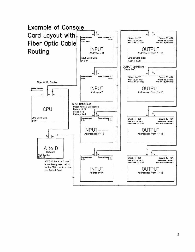
from all sides for the attachment of cables. See the sample console layout schematic.
INPUT Circuit Cards - 2 x 64 = 128 inputs on each card
These cards are mounted in the console with four (4) screws thru plastic standoffs. They need to be
accessible from all sides for the attachment of cables. These should be located nearest the inputs they will
be reading. See the sample console layout schematic.
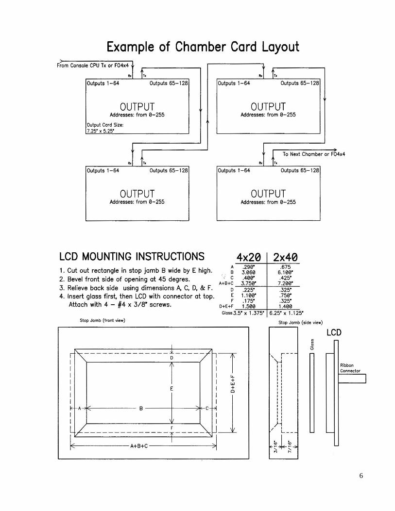
OUTPUT Circuit Cards - 2 x 64 = 128 outputs on each card
These cards are mounted in the console and pipe chambers with four (4) screws thru plastic standoffs.
They need to be accessible from all sides for the attachment of cables. These cards should be mounted
nearest the magnets they will be controlling.
A to D Circuit Card and Potentiometers
These are used in conjunction with each other to read the swell and crescendo pedal positions.
LCD
This is mounted (see LCD drawing) in clear line of sight of organist.
MIDI IN/THRU/OUT Connector Card
This card is installed on the console with four (4) screws thru plastic standoffs in a convenient place for the
organist to attach the MIDI cables.
RIBBON CABLE
This cable connects the LCD, MIDI connector card, and any console indicator lights to the CPU circuit
card.
FIBER OPTIC CABLES
These connect all of the circuit cards together. See the sample console layout schematic.
5
6
7
III. POWERS AND GROUNDS
110VAC CIRCUIT FOR POWER SUPPLY/RECTIFIER
An independent circuit shall be provided for the power supply/rectifier, in metal conduit, with a green wire
ground terminating at the water meter or a ground rod. This is called a green wire ground circuit, or
computer circuit.
110VAC CIRCUIT FOR BLOWER
The circuit for the blower must be independent from the above circuit for the power supply/rectifier.
ON/OFF SWITCH
A 24VAC transformer has to be supplied with the 110VAC disconnect as shown in power source drawing,
to energize a relay which turns on the power supply/rectifier.
POWER SUPPLY CABLES
LOGIC VOLTAGE: Each circuit card must be supplied with voltage for the logic. This logic voltage is
attached at the green barrier block on the CPU card, the green barrier block on the Input cards, and at the
center green barrier block on the Output cards. The +VDC must be fused as follows: based on ½ amp per
circuit board with a maximum fuse size of 3 amps.
MAGNET COIL VOLTAGE: This only applies to the OUTPUT cards and is covered in V. Outputs.
Color Code: yellow = +12vdc or + power supply voltage
Black = GND or - minus
Red = +5vcc
Orange = +3.3vdc
NOTE: Ground and Minus are not necessarily equivalent in DC terminology. Ground means zero
potential, minus is below zero, and plus or positive is above zero.

8
9
IV. INPUTS
DEFINITION
Inputs are keyboards, pedalboard, crescendo and swell box rollers, stop switches, pistons, and coupler
switches. These inputs are a simple switch circuit with one side of the switch being common (attached to
GND), and the opposite side of the switch being wired to the connector to the Input circuit card. These
inputs are wired and laced into cables with connectors which plug onto the Input cards. Please note
that these input cables must be physically separated from all output cables to minimize crosstalk.
These inputs are wired to pins in groups of 64, these 64 pin groups being assigned definitions according to
the following table at the time of power up programming.
KEYBOARDS
There is a maximum of nine, each wired to one connector from 1-61
PEDALBOARD and CRESCENDO
The Pedalboard is wired on pins 1-32 and the Crescendo is wired to the same connector on
pins 33-64. If the AtoD function is being used for the Swell Box Pedals and Crescendo Pedal,
then pins 33-64 can be piston inputs.
STOPS 1
This 64 pin group may include any or all of the following: Swell Box Rollers, MIDI Stops,
Couplers, Stops, and Pistons. The Swell Box Roller Pins that are to be used for MIDI Volume
must be wired in the range of 1-16. All the rest of the input pins in this group can be in any
order.
STOPS 2
Couplers, Stops, Pistons
STOPS 3
Stops
STOPS 4
Stops
STOPS 5
Stops
PISTONS 1
Pistons
PISTONS 2
Pistons
WIRING HINTS
Commons - are tied to power supply GROUND or – minus.
Pistons - order of piston wiring is not important as piston definitions are programmed.
Couplers - order of coupler wiring is not important as coupler definitions are programmed.
Connector Pin Order - Input connectors are wired in ascending number order. When holding connector in
horizontal position with pin 1 in lower left position: pin 2 is above pin 1 in upper row, pin 3 is in
lower row to the right of pin 1, pin 4 is above pin 3 in upper row and so on. Please note that the
numbering order is different from output connectors.
Pin List - Keep a written list of all of the Input wiring on the furnished spreadsheets.
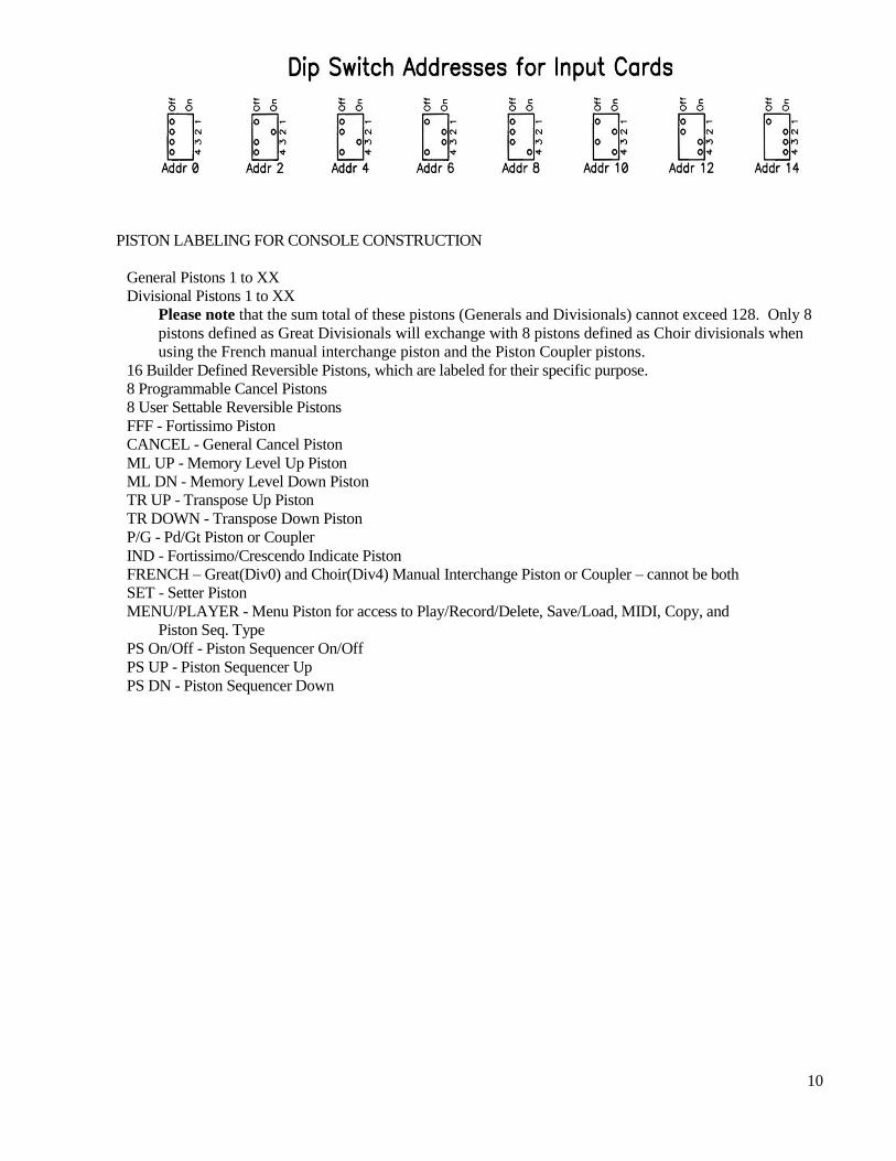
Input Card Addresses - Each Input Card has to be given an unique even number address starting with 0 so
the correct data will be transmitted to the CPU circuit card. This address (in binary number form) is
set with a DIP Switch on each Input circuit card.
10
PISTON LABELING FOR CONSOLE CONSTRUCTION
General Pistons 1 to XX
Divisional Pistons 1 to XX
Please note that the sum total of these pistons (Generals and Divisionals) cannot exceed 128. Only 8
pistons defined as Great Divisionals will exchange with 8 pistons defined as Choir divisionals when
using the French manual interchange piston and the Piston Coupler pistons.
16 Builder Defined Reversible Pistons, which are labeled for their specific purpose.
8 Programmable Cancel Pistons
8 User Settable Reversible Pistons
FFF - Fortissimo Piston
CANCEL - General Cancel Piston
ML UP - Memory Level Up Piston
ML DN - Memory Level Down Piston
TR UP - Transpose Up Piston
TR DOWN - Transpose Down Piston
P/G - Pd/Gt Piston or Coupler
IND - Fortissimo/Crescendo Indicate Piston
FRENCH – Great(Div0) and Choir(Div4) Manual Interchange Piston or Coupler – cannot be both
SET - Setter Piston
MENU/PLAYER - Menu Piston for access to Play/Record/Delete, Save/Load, MIDI, Copy, and
Piston Seq. Type
PS On/Off - Piston Sequencer On/Off
PS UP - Piston Sequencer Up
PS DN - Piston Sequencer Down
11
V. OUTPUTS
DEFINITION
These are either magnet coils or indicator lights, either in the console or pipe chamber(s).
CONSOLE INDICATOR LIGHTS
There are four (4) indicator light controls available, Fortissimo, Crescendo, Set, and Player;
these are wired as positive common, current sinking circuits with the switched side of the
light connected to the ribbon cable from the CPU card which is described in section VI.
STOP ON/OFF COILS
For each input group Stops 1-5 that is used for stops and couplers, there will have to be two
(2) groups of 64 outputs. The first group corresponds with Inputs 1-32, and the second group of
64 corresponds with Inputs 33-64. Each 64 pin connector grouping has parallel rows of 32
pins, one row (starting with the number 1 or 65) being ON coils and the opposite row (starting
with the number 33 or 97) being OFF coils. These output connector pin numbers must match
the input connector pin numbers. For example, if some input pins are skipped, the same
number of pins in the order will have to be skipped on the corresponding output connectors.
MAGNET COILS IN THE PIPE CHAMBERS
There are 128 outputs (pins) per Output circuit card using two 64 pin connectors arranged in 2
rows of 32. The wiring from the first 64 pin connector can continue to the second 64 pin
connector which then is considered to be pins 65 through 128.
Unit magnets:
These are wired in ascending consecutive order with one rank or partial offset
rank following another with no need to skip pins in between. This order can
be either chromatic or diatonic (C or C# side).
Primary actions for straight chests:
These are wired in ascending consecutive order, using either chromatic or
diatonic (C or C# side) order.
Stop actions for straight chests:
These are wired in ascending consecutive order - the same order as the input
stop actions were wired. The tremolos are included with this group.
Swell Box(es):
These are wired in ascending consecutive order - the same order as the inputs
are wired.
WIRING HINTS
Pin List - Keep a written list of all of the Output wiring on the furnished spreadsheets.
Output Card Addresses - Each Output Card has to be given an unique address so that the correct data
coming from the CPU circuit card will be recognized. This address (in binary number form) is
set with a DIP Switch on each Output circuit card.

12
13
OUTPUT CIRCUIT CARD TYPE - Positive Common - 2803A
Outputs are wired as a current sinking circuit with the common side of the coil wired to POSITIVE and the
switched side of the coil wired to the connector. All magnet coils must have a unique diode associated with
them. In order to use the diode internal to the driver chip, you must hook up the wiring exactly as stated
here, otherwise you must locate a diode right at the terminals of the coil. This Positive Common circuit
board takes care of all the diodes, fusing, and voltage polarities if you hook it up according to these
directions. The commons are split into 8 pin or magnet groups. These are to be hooked up at the green
barrier blocks labeled C1 thru C16.
The groupings are as follows:
Pins Common Fuse +VDx 1-4 and 33-36 C1 Fuse 1 1
5-8 and 37-40 C2 Fuse 2 1
9-12 and 41-44 C3 Fuse 3 1
13-16 and 45-48 C4 Fuse 4 1
17-20 and 49-52 C5 Fuse 5 2
21-24 and 53-56 C6 Fuse 6 2
25-28 and 57-60 C7 Fuse 7 2
29-32 and 61-64 C8 Fuse 8 2
65-68 and 97-100 C9 Fuse 9 3
69-72 and 101-104 C10 Fuse 10 3
73-76 and 105-108 C11 Fuse 11 3
77-80 and 109-112 C12 Fuse 12 3
81-84 and 113-116 C13 Fuse 13 4
85-88 and 117-120 C14 Fuse 14 4
89-92 and 121-124 C15 Fuse 15 4
93-96 and 125-128 C16 Fuse 16 4
Each of these groups of 8 has a fuse associated with it above the barrier block. These fuses are not labeled
but lay in respective order with the commons. The fuses are 2AG, quick blow glass, with a 2amp rating
matching the load of the magnets, with a maximum size of 2 amps.
You must wire your commons in these groups. To test the wiring for correct grouping of commons and
fuses, remove all but one fuse and test the 8 pins of the corresponding group. There are no exceptions to
this wiring layout.
The VDC and GND for the logic are located on the center green barrier block.
The +Vdc and GND for the magnets are located on the large green barrier blocks between the commons.
These +Vx terminals are unique and separate, labeled +V1, +V2, + V3, and +V4, with each of the four
feeding the 4 commons nearest to it. These +VDC terminals must be fused externally at the power supply,
with a fuse not to exceed 5 amps. The GND terminal of the magnet coil power supply must be hooked to
the GND terminals with gauge size and number matching the +V1, +V2, +V3, and +V4 wires.
If separate power supplies are used for logic and magnet coils on an Output card, their grounds (-) must be
tied together.

14
OUTPUT CIRCUIT CARD TYPE – Ground Common – 2981A - .5a per pin max.
Outputs are wired as a current sourcing circuit with the common side of the coil wired to GROUND (-) and
the switched side of the coil wired to the connector. All magnet coils must have a unique diode associated
with them. In order to use the diode internal to the driver chip, you must hook up the wiring exactly as
stated here, otherwise you must locate a diode right at the terminals of the coil. This Ground Common
circuit board takes care of all the diodes, fusing, and voltage polarities if you hook it up according to these
directions:
Pins Fuse +VDx 1-4 and 33-36 F1 1
5-8 and 37-40 F2 1
9-12 and 41-44 F3 1
13-16 and 45-48 F4 1
17-20 and 49-52 F5 2
21-24 and 53-56 F6 2
25-28 and 57-60 F7 2
29-32 and 61-64 F8 2
65-68 and 97-100 F9 3
69-72 and 101-104 F10 3
73-76 and 105-108 F11 3
77-80 and 109-112 F12 3
81-84 and 113-116 F13 4
85-88 and 117-120 F14 4
89-92 and 121-124 F15 4
93-96 and 125-128 F16 4
Each of these groups of 8 has a fuse associated with it above the barrier block. These fuses are 2AG, quick
blow glass, with a 2amp rating matching the load of the magnets, with a maximum size of 2 amps.
The Vdc and GND for the magnets are located on the 4 terminal barrier blocks labeled GND, +V1, +V2
and +V4, +V3, GND. The positive (+) terminal of power supply that is driving the magnet coils must be
hooked to each of these +Vx terminals through a fuse with a maximum size of 3Amps (when driving a
combination action in the console, this will have to be raised to a maximum of 5A). The GND (-) terminal
of this power supply that is driving the magnets must be hooked to the GND terminals of the +Vx barrier
blocks, these GND wires matching the +Vx terminal wires in gauge size and number.
The VDC and GND for the logic are located on the center green barrier block.
If separate power supplies are used for logic and magnet coils on an Output card, their grounds (-) must be
tied together.

15
OUTPUT CIRCUIT CARD TYPE – Ground Common – 2987A - .35a per pin max.
Outputs are wired as a current sourcing circuit with the common side of the coil wired to GROUND (-) and
the switched side of the coil wired to the connector. All magnet coils must have a unique diode associated
with them. In order to use the diode internal to the driver chip, you must hook up the wiring exactly as
stated here. Otherwise you must locate a diode right at the terminals of the coil. This Ground Common
circuit board takes care of all the diodes and voltage polarities if you hook it up according to these
directions:
Pins +VDx 1-16 and 33-48 1
17-32 and 49-64 2
65-84 and 97-112 3
85-96 and 113-128 4
The VDC and GND for the magnets are located on the 4 terminal barrier blocks labeled +V1, +V2, GND
and GND, +V4, +V3. The positive (+) terminal of power supply that is driving the magnet coils must be
hooked to each of these +Vx terminals through a fuse with a maximum size of 3Amps. The GND (-)
terminal of this power supply that is driving the magnets must be hooked to the GND terminals of the +Vx
barrier blocks, with wire gauge size and number matching that of the +Vx wires.
The VDC and GND for the logic are located on the center green barrier block.
If separate power supplies are used for logic and magnet coils on an Output card, their grounds (-) must be
tied together.

16
VI. FIBER OPTICS and RIBBON CABLE
INSTALLATION OF THE FIBER OPTIC CABLES
A fiber optic loop will connect all of the input and output circuit cards in the console to the CPU circuit
card. Start at the INPUT TX console port (grey) on the CPU card, progress thru all of the INPUT cards (in
blue, out grey) in ascending consecutive address order, then progress thru the OUTPUT cards (in blue, out
grey) in ascending consecutive order, next thru the A to D card (in blue, out grey) if being used, and return
to the CPU card at the INPUT RX (blue) port. A fiber optic daisy chain will connect the CPU card and all
of the OUTPUT cards in the pipe chamber. Start this chain at the OUTPUT TX chamber (grey) on the
CPU card and run through all of the Output (in blue, out grey) cards in the pipe chamber, in any order of
addresses. Please see examples of console and chamber card layouts in II. Physical Components.
TERMINATION OF PLASTIC FIBER OPTIC CABLE
1. After cutting the cable to the desired length, strip off
approximately .3” of the outer jacket with a 16 ga. wire stripper.
2. Place the crimp ring and the connector over the end of the cable,
with adhesive if desired, the clear fiber should protrude about
.12”, and crimp the ring in place with a generic crimping tool,
slightly oval is all that is needed. After glue has set
(if used), trim off excess clear fiber with flush cut
side cutter to clear protrudes .06”.
3. Place a piece of 600 grit sandpaper on a flat smooth
surface. Insert the now crimped connector with
protruding cable into the polishing fixture,and with the
fixture flat on the sandpaper and cable perpendicular to
sandpaper surface, draw large figure eight patterns until
connector end is flush. Repeat this process using the pink
3 micron lapping film.
FIBER OPTIC CABLE COUPLING
Fiber optic cable can be coupled, for example a movable
console with or without multiple locations. Shown is the plastic to plastic coupling, this can be done with
glass to glass in the same fashion.
17
TRANSLATION OF FIBER CABLE TYPES
When the length of a single run of fiber cable exceeds 100’, it is necessary to translate the cable to glass
that can be used in single run lengths of 4km. This is done with a small circuit board at the start of this run
converting from plastic to glass cable, and at the end of the run a similar small circuit board converting
from glass to plastic.
INSTALLATION of the RIBBON CABLE to LCD, MIDI CONNECTOR, and LIGHTS
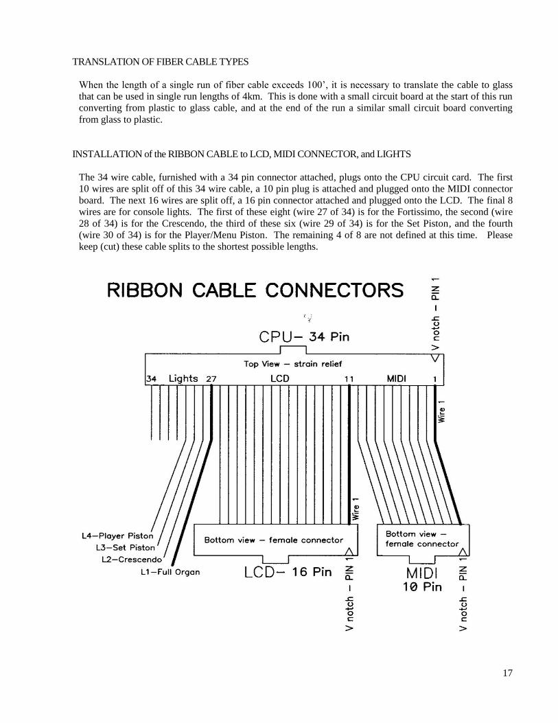
The 34 wire cable, furnished with a 34 pin connector attached, plugs onto the CPU circuit card. The first
10 wires are split off of this 34 wire cable, a 10 pin plug is attached and plugged onto the MIDI connector
board. The next 16 wires are split off, a 16 pin connector attached and plugged onto the LCD. The final 8
wires are for console lights. The first of these eight (wire 27 of 34) is for the Fortissimo, the second (wire
28 of 34) is for the Crescendo, the third of these six (wire 29 of 34) is for the Set Piston, and the fourth
(wire 30 of 34) is for the Player/Menu Piston. The remaining 4 of 8 are not defined at this time. Please
keep (cut) these cable splits to the shortest possible lengths.
18
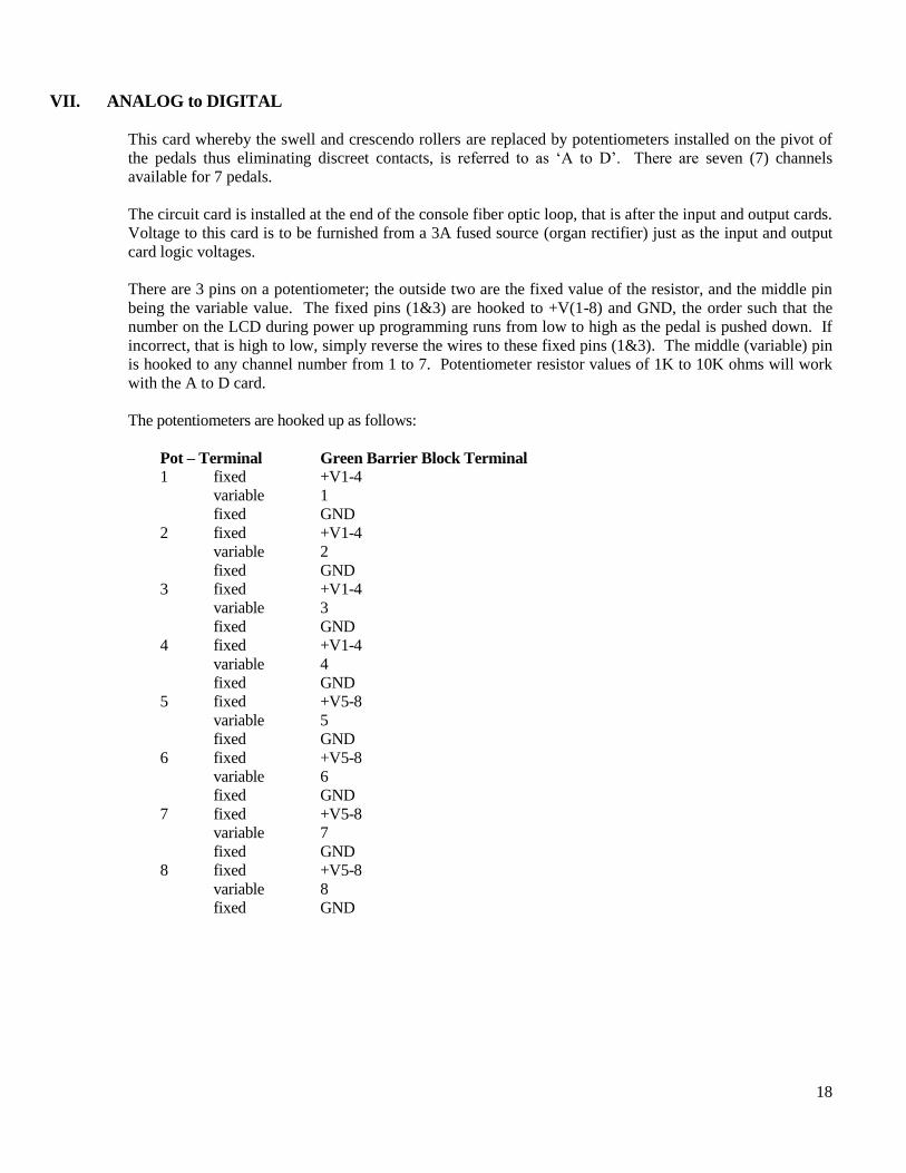
VII. ANALOG to DIGITAL
This card whereby the swell and crescendo rollers are replaced by potentiometers installed on the pivot of
the pedals thus eliminating discreet contacts, is referred to as ‘A to D’. There are seven (7) channels
available for 7 pedals.
The circuit card is installed at the end of the console fiber optic loop, that is after the input and output cards.
Voltage to this card is to be furnished from a 3A fused source (organ rectifier) just as the input and output
card logic voltages.
There are 3 pins on a potentiometer; the outside two are the fixed value of the resistor, and the middle pin
being the variable value. The fixed pins (1&3) are hooked to +V(1-8) and GND, the order such that the
number on the LCD during power up programming runs from low to high as the pedal is pushed down. If
incorrect, that is high to low, simply reverse the wires to these fixed pins (1&3). The middle (variable) pin
is hooked to any channel number from 1 to 7. Potentiometer resistor values of 1K to 10K ohms will work
with the A to D card.
The potentiometers are hooked up as follows:
Pot – Terminal Green Barrier Block Terminal
1 fixed +V1-4
variable 1
fixed GND
2 fixed +V1-4
variable 2
fixed GND
3 fixed +V1-4
variable 3
fixed GND
4 fixed +V1-4
variable 4
fixed GND
5 fixed +V5-8
variable 5
fixed GND
6 fixed +V5-8
variable 6
fixed GND
7 fixed +V5-8
variable 7
fixed GND
8 fixed +V5-8
variable 8
fixed GND
19
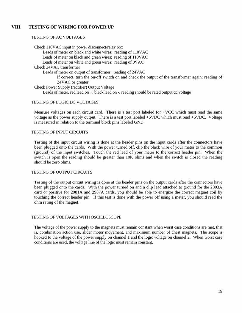
VIII. TESTING OF WIRING FOR POWER UP
TESTING OF AC VOLTAGES
Check 110VAC input in power disconnect/relay box
Leads of meter on black and white wires: reading of 110VAC
Leads of meter on black and green wires: reading of 110VAC
Leads of meter on white and green wires: reading of 0VAC
Check 24VAC transformer
Leads of meter on output of transformer: reading of 24VAC
If correct, turn the on/off switch on and check the output of the transformer again: reading of
24VAC or greater
Check Power Supply (rectifier) Output Voltage
Leads of meter, red lead on +, black lead on -, reading should be rated output dc voltage
TESTING OF LOGIC DC VOLTAGES
Measure voltages on each circuit card. There is a test port labeled for +VCC which must read the same
voltage as the power supply output. There is a test port labeled +5VDC which must read +5VDC. Voltage
is measured in relation to the terminal block pins labeled GND.
TESTING OF INPUT CIRCUITS
Testing of the input circuit wiring is done at the header pins on the input cards after the connectors have
been plugged onto the cards. With the power turned off, clip the black wire of your meter to the common
(ground) of the input switches. Touch the red lead of your meter to the correct header pin. When the
switch is open the reading should be greater than 10K ohms and when the switch is closed the reading
should be zero ohms.
TESTING OF OUTPUT CIRCUITS
Testing of the output circuit wiring is done at the header pins on the output cards after the connectors have
been plugged onto the cards. With the power turned on and a clip lead attached to ground for the 2803A
card or positive for 2981A and 2987A cards, you should be able to energize the correct magnet coil by
touching the correct header pin. If this test is done with the power off using a meter, you should read the
ohm rating of the magnet.
TESTING OF VOLTAGES WITH OSCILLOSCOPE
The voltage of the power supply to the magnets must remain constant when worst case conditions are met, that
is, combination action use, slider motor movement, and maximum number of chest magnets. The scope is
hooked to the voltage of the power supply on channel 1 and the logic voltage on channel 2. When worst case
conditions are used, the voltage line of the logic must remain constant.
20
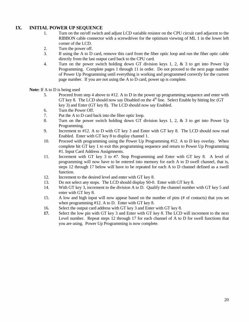
IX. INITIAL POWER UP SEQUENCE 1. Turn on the on/off switch and adjust LCD variable resistor on the CPU circuit card adjacent to the
RIBBON cable connector with a screwdriver for the optimum viewing of ML 1 in the lower left
corner of the LCD.
2. Turn the power off.
3. If using the A to D card, remove this card from the fiber optic loop and run the fiber optic cable
directly from the last output card back to the CPU card.
4. Turn on the power switch holding down GT division keys 1, 2, & 3 to get into Power Up
Programming. Complete pages 1 through 11 in order. Do not proceed to the next page number
of Power Up Programming until everything is working and programmed correctly for the current
page number. If you are not using the A to D card, power up is complete.
Note: If A to D is being used
5. Proceed from step 4 above to #12. A to D in the power up programming sequence and enter with
GT key 8. The LCD should now say Disabled on the 4th line. Select Enable by hitting Inc (GT
key 3) and Enter (GT key 8). The LCD should now say Enabled.
6. Turn the Power Off.
7. Put the A to D card back into the fiber optic loop.
8. Turn on the power switch holding down GT division keys 1, 2, & 3 to get into Power Up
Programming.
9. Increment to #12. A to D with GT key 3 and Enter with GT key 8. The LCD should now read
Enabled. Enter with GT key 8 to display channel 1.
10. Proceed with programming using the Power Up Programming #12. A to D key overlay. When
complete hit GT key 1 to exit this programming sequence and return to Power Up Programming
#1. Input Card Address Assigmnents.
11. Increment with GT key 3 to #7. Stop Programming and Enter with GT key 8. A level of
programming will now have to be entered into memory for each A to D swell channel, that is,
steps 12 through 17 below will have to be repeated for each A to D channel defined as a swell
function.
12. Increment to the desired level and enter with GT key 8.
13. Do not select any stops. The LCD should display S0-0. Enter with GT key 8.
14. With GT key 3, increment to the division A to D. Qualify the channel number with GT key 5 and
enter with GT key 8.
15. A low and high input will now appear based on the number of pins (# of contacts) that you set
when programming #12. A to D. Enter with GT key 8.
16. Select the output card address with GT key 3 and Enter with GT key 8.
17. Select the low pin with GT key 3 and Enter with GT key 8. The LCD will increment to the next
Level number. Repeat steps 12 through 17 for each channel of A to D for swell functions that
you are using. Power Up Programming is now complete.

21
X. TROUBLE SHOOTING
SYSTEMATIC APPROACH
In order to solve a malfunction quickly and correctly, a systematic approach is required. The problem has
to be isolated and then tested correctly. The steps in this approach are:
1. Check for correct DC voltages
2. Test problem circuit
3. Repair
This is a repeat of VII. Testing of Wiring for Power Up.
NOTE: If the problem seems to be a circuit board problem, swap the board with one that is known to be
good. The boards may be bypassed with voltage and fiber optics to keep the system functioning if a
replacement board is not available. However, the CPU and INPUT card address 0 must always be in the
system.
FUSES - check with an ohm meter, do not rely on checking visually only. There are a variety of fuses, in
amp rating and location; these are covered in previous sections III, V, and VII.
NOTE: In the event of the need to call us for assistance, please have your documentation, voltmeter,
and a hands free phone ready so that we can help you.
NOTE: Most problems encountered are either voltage or wiring. Without the use of both a digital
multimeter and an oscilloscope to monitor the quantity and QUALITY of the voltage, trouble
shooting is at best a shot in the dark.


