Refer also to the instructions included with the aftermarket radio.
KNOWLEDGE IS POWEREnhance your installation and fabrication skills by enrolling in the most recognized and respected mobile electronics school in our industry.Log onto www.installerinstitute.com or call 800-354-6782 for more information and take steps toward a better tomorrow.
Metra recommends MECPcertified technicians
1
3
4
MITSUBISHI GALANT 2004-UP
99-7012 DASH DISASSEMBLY
Disconnect the negative battery ter-minal to prevent an accidental shortcircuit.
1
Unclip the radio trim panel includingthe climate controls and radio con-trols. Unplug and remove the panel.(Figure A)
Remove (4) Phillips screws securingradio chassis to sub dash. Unplugand remove the chassis. (Figure B)
Remove (4) Phillips screws securingthe climate controls to the radiopanel. Remove the climate controlsand retain the screws and the climatecontrols for reinstallation during kitassembly. (Figure C)
Continue to kit assembly
2
C
B
A
2
99-7012 KIT PREPARATION
99-7012 KIT ASSEMBLY
A
BC
DIN RADIO PROVISION WITH POCKET
Slide the DIN cage into the radio hous-ing and secure by bending the metallocking outward. (Figure A)
1
Secure the climate controls to theradio housing using the factory hard-ware. (Figure A)
1
Slide the aftermarket radio into thecage until it snaps into place. (Figure B)
2
Snap the pocket into the radio housing.(Figure C)
3
Continue to final assembly.
*Note: Refer also to the instructions included with the aftermarket radio.
A
99-7012 KIT ASSEMBLY
3
A
B
C
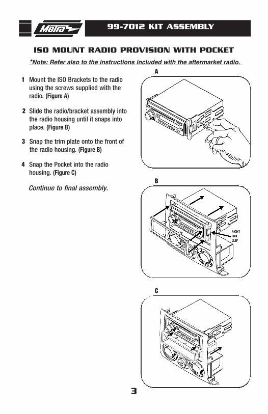
ISO MOUNT RADIO PROVISION WITH POCKET
Mount the ISO Brackets to the radiousing the screws supplied with theradio. (Figure A)
1
Slide the radio/bracket assembly intothe radio housing until it snaps intoplace. (Figure B)
2
Snap the trim plate onto the front ofthe radio housing. (Figure B)
3
Snap the Pocket into the radio housing. (Figure C)
4
Continue to final assembly.
*Note: Refer also to the instructions included with the aftermarket radio.
99-7012 KIT ASSEMBLY
4
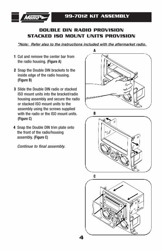
DOUBLE DIN RADIO PROVISIONSTACKED ISO MOUNT UNITS PROVISION
Cut and remove the center bar fromthe radio housing. (Figure A)
1
Snap the Double DIN brackets to theinside edge of the radio housing.(Figure B)
2
Slide the Double DIN radio or stackedISO mount units into the bracket/radiohousing assembly and secure the radioor stacked ISO mount units to theassembly using the screws suppliedwith the radio or the ISO mount units.(Figure C)
3
Snap the Double DIN trim plate ontothe front of the radio/housing assembly. (Figure C)
4
Continue to final assembly.
*Note: Refer also to the instructions included with the aftermarket radio.
A
B
C
99-7012 FINAL ASSEMBLY
FINAL ASSEMBLY
(A) Strip wire ends back 1/2"
B) Twist ends together
C) Solder
D) Tape
A
B
C
D
Locate the factory wiring harness in the dash. Metra recommends using the proper mating adapter and making connections as shown. (Isolate and individ-ually tape off the ends of any unused wires to prevent electrical short circuit.)
Re-connect the negative battery terminal and test the unit for proper operation.
Reassemble radio and dash assemblies in reverse order of disassembly.
1
2
3
FINAL WIRING CONNECTIONS
Make wiring connections using the EIA color code chart shown below and the instructions included with thehead unit. Metra recommends making connections as shown below; Strip, Splice, Solder, Tape. Isolate and
individually tape off ends of any unused wires to prevent electrical short circuit.
METRA / EIA WIRING CODE12V Ignition / Acc . . . . . . . . . . Red
12V Batt / Memory. . . . . . . . . Yellow
Ground. . . . . . . . . . . . . . . . . . Black*
Power Antenna. . . . . . . . . . . . Blue
Amp Turn-On . . . . . . . . . . . . . Blue / White
Amp Ground. . . . . . . . . . . . . . Black / White
Right Front (-). . . . . . . . . . . . . Gray/ Black
Left Front (+) . . . . . . . . . . . . . White
Left Front (-). . . . . . . . . . . . . . White / Black
Right Rear (+) . . . . . . . . . . . . Violet
Right Rear (-) . . . . . . . . . . . . . Violet / Black
Left Rear (+) . . . . . . . . . . . . . Green
Left Rear (-) . . . . . . . . . . . . . . Green / Black
*NOTE: When a Black wire is not present, ground radio to vehicle chassis. All colors may not be present on all leads due to manufacturer’s specifications.