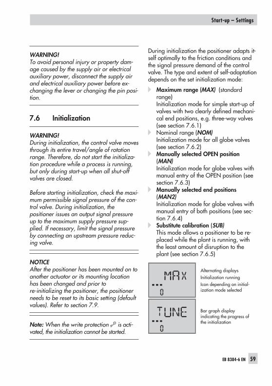
Series 3730 Electropneumatic Positioner Type 3730-6 with HART ® communication and pressure sensors Mounting and Operating Instructions EB 8384-6 EN Firmware version 1.01 Edition February 2012 Fig. 1 · Type 3730-6
Transcript
Series 3730Electropneumatic PositionerType 3730-6
with HART®communication and pressure sensors
Mounting andOperating Instructions
EB 8384-6 ENFirmware version 1.01Edition February 2012
Fig. 1 · Type 3730-6
2 EB 8384-6 EN
DANGER!indicates a hazardous situation which, if notavoided, will result in death or serious injury.
WARNING!indicates a hazardous situation which, if notavoided, could result in death or seriousinjury.
NOTICEindicates a property damage message.
Note: Supplementary explanations, informa-tion and tips
Definitions of the signal words used in these instructions
For your own safety, follow these instructions concerning the mounting, start-up and opera-tion of the positioner:
� The positioner is to be mounted, started up or operated only by trained andexperienced personnel familiar with the product.According to these Mounting and Operating Instructions, trained personnel refers toindividuals who are able to judge the work they are assigned to and recognizepossible dangers due to their specialized training, their knowledge and experience aswell as their knowledge of the applicable standards.
� Explosion-protected versions of this positioner may only be operated by personnelwho have undergone special training or instructions or who are authorized to workon explosion-protected devices in hazardous areas. Refer to section 11.
� Any hazards that could be caused by the process medium, the operating pressure, thesignal pressure or by moving parts of the control valve are to be prevented by meansof the appropriate measures.
� If inadmissible motions or forces are produced in the actuator as a result of the supplypressure, the supply pressure must be restricted by means of a suitable supplypressure reducing station.
To avoid damage to any equipment, the following also applies:
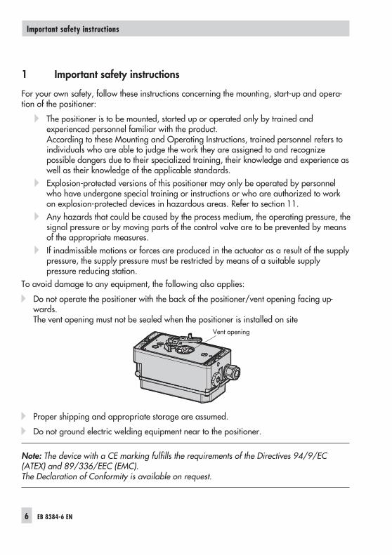
� Do not operate the positioner with the back of the positioner/vent opening facing up-wards.The vent opening must not be sealed when the positioner is installed on site
� Proper shipping and appropriate storage are assumed.
� Do not ground electric welding equipment near to the positioner.
Note: The device with a CE marking fulfills the requirements of the Directives 94/9/EC(ATEX) and 89/336/EEC (EMC).The Declaration of Conformity is available on request.
6 EB 8384-6 EN
Important safety instructions
Vent opening
2 Article code
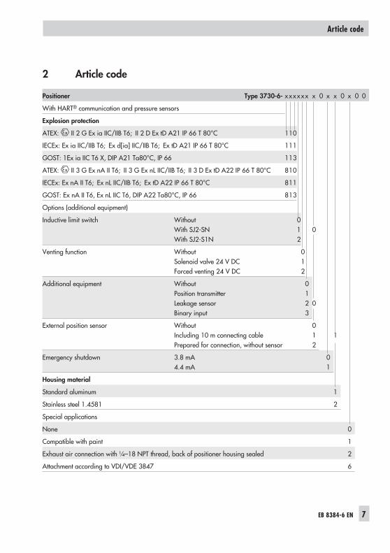
Positioner Type 3730-6- xxxxxx x 0 x x 0 x 0 0
With HART® communication and pressure sensors
Explosion protection
ATEX: II 2 G Ex ia IIC/IIB T6; II 2 D Ex tD A21 IP 66 T 80°C 110
IECEx: Ex ia IIC/IIB T6; Ex d[ia] IIC/IIB T6; Ex tD A21 IP 66 T 80°C 111
GOST: 1Ex ia IIC T6 X, DIP A21 Ta80°C, IP 66 113
ATEX: II 3 G Ex nA II T6; II 3 G Ex nL IIC/IIB T6; II 3 D Ex tD A22 IP 66 T 80°C 810
IECEx: Ex nA II T6; Ex nL IIC/IIB T6; Ex tD A22 IP 66 T 80°C 811
GOST: Ex nA II T6, Ex nL IIC T6, DIP A22 Ta80°C, IP 66 813
External position sensor WithoutIncluding 10 m connecting cablePrepared for connection, without sensor
012
1
Emergency shutdown 3.8 mA4.4 mA
01
Housing material
Standard aluminum 1
Stainless steel 1.4581 2
Special applications
None 0
Compatible with paint 1
Exhaust air connection with ¼–18 NPT thread, back of positioner housing sealed 2
Attachment according to VDI/VDE 3847 6
Article code
EB 8384-6 EN 7
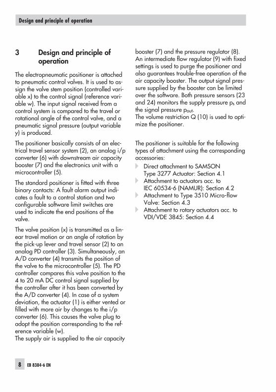
3 Design and principle ofoperation
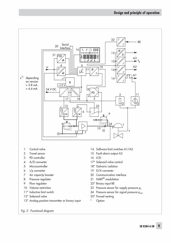
The electropneumatic positioner is attachedto pneumatic control valves. It is used to as-sign the valve stem position (controlled vari-able x) to the control signal (reference vari-able w). The input signal received from acontrol system is compared to the travel orrotational angle of the control valve, and apneumatic signal pressure (output variabley) is produced.
The positioner basically consists of an elec-trical travel sensor system (2), an analog i/pconverter (6) with downstream air capacitybooster (7) and the electronics unit with amicrocontroller (5).
The standard positioner is fitted with threebinary contacts: A fault alarm output indi-cates a fault to a control station and twoconfigurable software limit switches areused to indicate the end positions of thevalve.
The valve position (x) is transmitted as a lin-ear travel motion or an angle of rotation bythe pick-up lever and travel sensor (2) to ananalog PD controller (3). Simultaneously, anA/D converter (4) transmits the position ofthe valve to the microcontroller (5). The PDcontroller compares this valve position to the4 to 20 mA DC control signal supplied bythe controller after it has been converted bythe A/D converter (4). In case of a systemdeviation, the actuator (1) is either vented orfilled with more air by changes to the i/pconverter (6). This causes the valve plug toadopt the position corresponding to the ref-erence variable (w).The supply air is supplied to the air capacity
booster (7) and the pressure regulator (8).An intermediate flow regulator (9) with fixedsettings is used to purge the positioner andalso guarantees trouble-free operation of theair capacity booster. The output signal pres-sure supplied by the booster can be limitedover the software. Both pressure sensors (23and 24) monitors the supply pressure ps andthe signal pressure pout.The volume restriction Q (10) is used to opti-mize the positioner.
The positioner is suitable for the followingtypes of attachment using the correspondingaccessories:� Direct attachment to SAMSON
Type 3277 Actuator: Section 4.1� Attachment to actuators acc. to
IEC 60534-6 (NAMUR): Section 4.2� Attachment to Type 3510 Micro-flow
Valve: Section 4.3� Attachment to rotary actuators acc. to
VDI/VDE 3845: Section 4.4
8 EB 8384-6 EN
Design and principle of operation
EB 8384-6 EN 9
Design and principle of operation
1 Control valve2 Travel sensor3 PD controller4 A/D converter5 Microcontroller6 i/p converter7 Air capacity booster8 Pressure regulator9 Flow regulator10 Volume restriction11* Inductive limit switch12* Solenoid valve13* Analog position transmitter or binary input
The safety function is based on the shutdownof the i/p converter (6). This causes thepneumatic actuator to be vented and thevalve to move to its fail-safe position.
Monitoring of the input signal
The i/p converter is switched off when theinput signal of the positioner at terminals+11/–12 falls below 3.8 mA or 4.4 mA de-pending on the positioner version (a signalrange of 4 to 20 mA is required). SeeFig. 18 on page 48.
Monitoring the voltage supply(version with forced venting and solenoidvalve)
The i/p converter and the solenoid valve(when installed) are shut down whenever thevoltage at terminals +81/–82 falls below12 V (an input voltage of 24 V DC is re-quired). See Fig. 18 on page 48.
When the i/p converter is switched off bythe monitoring of the input signal or the volt-age supply, the fail-safe position S is acti-vated and is indicated on the positionerdisplay.
If required, the user can check the safetyfunction using the software.For more details, refer to the Operating In-structions EB 8389-1 EN on EXPERTplusValve Diagnostics.
3.2 Valve diagnostics
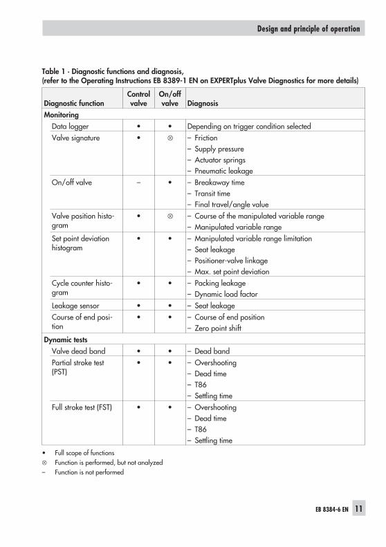
The EXPERTplus valve diagnostics are inte-grated into the positioner. They provide in-formation on the valve condition (see Ta-ble 1) and generate status messages toquickly pinpoint faults.
For more details, refer to the Operating In-structions EB 8389-1 EN on EXPERTplusValve Diagnostics.
3.3 Flow rate calculation
Due to the differential pressure measurement�p out, EXPERTplus is able to calculate theflow rate in a SAMSON Type 3241 orType 3251 Valve, provided all the parame-ters regarding the medium and the processhave been defined in the positioner.
For more details, refer to the Operating In-structions EB 8389-1 EN on EXPERTplusValve Diagnostics.
On/off valve – • – Breakaway time– Transit time– Final travel/angle value
Valve position histo-gram
• � – Course of the manipulated variable range– Manipulated variable range
Set point deviationhistogram
• • – Manipulated variable range limitation– Seat leakage– Positioner-valve linkage– Max. set point deviation
Cycle counter histo-gram
• • – Packing leakage– Dynamic load factor
Leakage sensor • • – Seat leakageCourse of end posi-tion
• • – Course of end position– Zero point shift
Dynamic testsValve dead band • • – Dead bandPartial stroke test(PST)
• • – Overshooting– Dead time– T86– Settling time
Full stroke test (FST) • • – Overshooting– Dead time– T86– Settling time
• Full scope of functions� Function is performed, but not analyzed– Function is not performed
Table 1 · Diagnostic functions and diagnosis,(refer to the Operating Instructions EB 8389-1 EN on EXPERTplus Valve Diagnostics for more details)
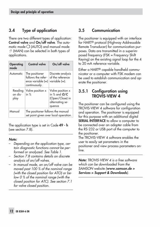
3.4 Type of application
There are two different types of application:Control valve and On/off valve. The auto-matic mode (AUTO) and manual mode
(MAN) can be selected in both types ofapplications.
Operatingmode
Control valve On/off valve
Automatic The positionerfollows the refer-ence variable (w)continuously.
Discrete analysisof the referencevariable (w).
Readingon dis-play
Valve position xin %
Valve position xin % and O/C(Open/Close) inalternating se-quence
Manual The positioner follows the manualset point given over local operation.
The application type is set in Code 49 - h(see section 7.8).
Note:– Depending on the application type, cer-
tain diagnostic functions cannot be per-formed or analyzed. See Table 1.
– Section 7.8 contains details on discreteanalysis of on/off valves.
– In manual mode, an on/off valve can bemoved past 100 % of the nominal range(with the closed position for ATO) or be-low 0 % of the nominal range (with theclosed position for ATC). See section 7.1for valve closed position.
3.5 Communication
The positioner is equipped with an interfacefor HART® protocol (Highway AddressableRemote Transducer) for communication pur-poses. Data are transmitted in a superim-posed frequency (FSK = Frequency ShiftKeying) on the existing signal loop for the 4to 20 mA reference variable.
Either a HART® capable handheld commu-nicator or a computer with FSK modem canbe used to establish communication and op-erate the positioner.
3.5.1 Configuration usingTROVIS-VIEW 4
The positioner can be configured using theTROVIS-VIEW 4 software for configurationand operation. The positioner is equippedfor this purpose with an additional digitalSERIAL INTERFACE to allow a computer tobe connected over an adapter cable fromthe RS-232 or USB port of the computer tothe positioner.The TROVIS-VIEW 4 software enables theuser to easily set parameters in thepositioner and view process parameters on-line.
Note: TROVIS-VIEW 4 is a free softwarewhich can be downloaded from theSAMSON website (www.samson.de >Services > Support & Downloads).
12 EB 8384-6 EN
Design and principle of operation
3.6 Additional equipment
Inductive limit switch
In the version with inductive limit switch, therotary shaft of the positioner carries an ad-justable tag which actuates the installedproximity switch. The optional inductive limitswitch (11) is connected to A1, while the re-maining software limit switch is connected toA2.
Solenoid valve
If the operating voltage for the solenoidvalve (12) falls under 12 V, the supply pres-sure for the i/p converter (6) is vented to theatmosphere. The positioner can no longeroperate and the control valve moves to thefail-safe position determined by the actua-tor, independent of the reference variable.In manual mode, the manual set point isreset to 0 %. A different manual set pointmust entered again.
Forced venting
If the voltage signal at terminals +81/–82falls below 12 V, the i/p converter (6) isde-energized. The positioner vents the actu-ator, causing valve to move to the fail-safeposition determined by the actuator, inde-pendent of the reference variable.
Analog position transmitter
The position transmitter (13) is a two-wiretransmitter and issues the travel sensor sig-nal as a 4 to 20 mA signal processed by themicrocontroller. Since this signal is issued in-dependent of the positioner’s input signal,the momentary travel/angle of rotation is
controlled in real-time. Additionally, the po-sition transmitter allows positioner faults tobe indicated over a signal current of< 2.4 mA or > 21.6 mA.
Leakage sensor
By upgrading the positioner with a leakagesensor, it is possible to detect seat leakagewhen the valve is in the closed position. Formore details, refer to the Operating Instruc-tions EB 8389-1 EN on EXPERTplus ValveDiagnostics.
Binary input
The optional binary input can be configured:� To connect a floating contact� To connect a non-floating contact (0 to
24 V DC)By selecting a certain function, one of thefollowing actions can be activated:� Transmit switching state
The switching state of the binary input islogged.
� Activate local write protectionAfter the first initialization, a local writeprotection can be activated. While thebinary input is active, no settings can bechanged at the positioner. The positionercannot be re-initialized. Configurationenabling over Code 3 is not active ( ).
� Start PSTThe positioner start a single partial stroketest. The test is performed with the set-tings in Code 49 - d2 to Code 49 - d9(refer to Operating InstructionsEB 8389-1 EN on EXPERTplus Valve Di-agnostics).
� Move valve to safety set pointAn on/off valve moves to the predeter-
EB 8384-6 EN 13
Design and principle of operation
mined safety set point when thepositioner is in automatic mode(AUTO). This function is not performed inthe manual mode (MAN) or fail-safeposition mode (SAFE).
� Switch AUTO/MANUALThe positioner changes from the auto-matic mode (AUTO) to the manualmode (MAN) or vice versa.This function is not performed if thepositioner is in the fail-safe positionmode (SAFE).
� Start data loggerThe data logger starts recording whenthe binary input is activated (refer to Op-erating Instructions EB 8389-1 EN onEXPERTplus Valve Diagnostics).
� Reset diagnosticsActive tests and monitoring are stoppedand the diagnostic data is reset once.
Additionally, the external solenoid valvefunction can be selected if a non-floatingcontact is configured:� External solenoid valve
The voltage for an external solenoidvalve is connected in parallel to terminals+81/–82. This allows the switching stateof the solenoid valve to be monitored.
Note: The optional binary input can only beconfigured using the operator software e.g.TROVIS-VIEW 4. The switching state istransmitted when the switch is closed by de-fault.
External position sensor
In this version, only the sensor is mounted tothe control valve. The positioner is located
separately from the valve.The connection of controlled variable (x) andoutput variable (y) signals to the valve is es-tablished by cable and piping for air.
14 EB 8384-6 EN
Design and principle of operation
3.7 Technical data
EB 8384-6 EN 15
Design and principle of operation
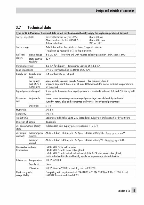
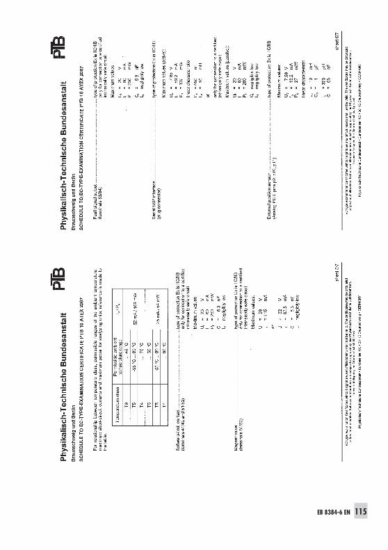
Type 3730-6 Positioner (technical data in test certificates additionally apply for explosion-protected devices)
Travel, adjustable Direct attachment to Type 3277: 3.6 to 30 mmAttachment acc. to IEC 60534-6: 3.6 to 200 mmRotary actuators: 24° to 100°
Travel range Adjustable within the initialized travel/angle of rotationTravel can be restricted to 1
5 at the maximum
Ref. vari-able w
Signal range 4 to 20 mA · Two-wire unit with reverse polarity protection · Min. span 4 mA
Static destruc-tion limit
30 V
Minimum current 3.6 mA for display · Emergency venting at � 3.8 mA
Load impedance � 9.2 V (corresponding to 460 � at 20 mA)
Supply air Supply pres-sure
1.4 to 7 bar (20 to 105 psi)
Air qualityISO 8573-1(2001-02)
Max. particle size and density: Class 4 · Oil content: Class 3pressure dew point: Class 3 or at least 10 K beneath the lowest ambient temperature tobe expected
Signal pressure (output) 0 bar up to the capacity of supply pressure · Limitable between 1.4 and 7.0 bar by soft-ware
Transit time Separately adjustable up to 240 seconds for supply air and exhaust air by software
Direction of action Reversible
Air consumption, steadystate
Independent from supply pressure approx. 110 ln/h
Air outputcapacity
Actuator pres-surized
At �p = 6 bar: 8.5 mn³/h · At �p = 1.4 bar: 3.0 mn³/h · KVmax (20 °C) = 0.09
Actuatorvented
At �p = 6 bar: 14.0 mn³/h · At �p = 1.4 bar: 4.5 mn³/h · KVmax (20 °C) = 0.15
Permissible ambienttemperature
–20 to +80 °C for all versions–45 to +80 °C with metal cable gland–25 to +80 °C with inductive limit switch (SJ2-S1N) and metal cable glandLimits in test certificate additionally apply for explosion-protected devices
Influences Temperature � 0.15 %/10 K
Supply air None
Vibration � 0.25 % up to 2000 Hz and 4 g acc. to IEC 770
Electromagneticcompatibility
Complying with requirements of EN 61000-6-2, EN 61000-6-3, EN 61326-1 andNAMUR Recommendation NE 21
16 EB 8384-6 EN
Design and principle of operation
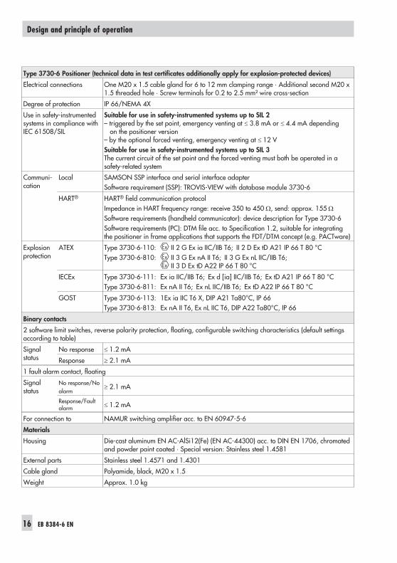
Type 3730-6 Positioner (technical data in test certificates additionally apply for explosion-protected devices)
Electrical connections One M20 x 1.5 cable gland for 6 to 12 mm clamping range · Additional second M20 x1.5 threaded hole · Screw terminals for 0.2 to 2.5 mm² wire cross-section
Degree of protection IP 66/NEMA 4X
Use in safety-instrumentedsystems in compliance withIEC 61508/SIL
Suitable for use in safety-instrumented systems up to SIL 2– triggered by the set point, emergency venting at � 3.8 mA or � 4.4 mA depending
on the positioner version– by the optional forced venting, emergency venting at � 12 VSuitable for use in safety-instrumented systems up to SIL 3The current circuit of the set point and the forced venting must both be operated in asafety-related system
Communi-cation
Local SAMSON SSP interface and serial interface adapterSoftware requirement (SSP): TROVIS-VIEW with database module 3730-6
HART® HART® field communication protocolImpedance in HART frequency range: receive 350 to 450 �, send: approx. 155 �
Software requirements (handheld communicator): device description for Type 3730-6Software requirements (PC): DTM file acc. to Specification 1.2, suitable for integratingthe positioner in frame applications that supports the FDT/DTM concept (e.g. PACTware)
Explosionprotection
ATEX Type 3730-6-110: II 2 G Ex ia IIC/IIB T6; II 2 D Ex tD A21 IP 66 T 80 °CType 3730-6-810: II 3 G Ex nA II T6; II 3 G Ex nL IIC/IIB T6;
II 3 D Ex tD A22 IP 66 T 80 °C
IECEx Type 3730-6-111: Ex ia IIC/IIB T6; Ex d [ia] IIC/IIB T6; Ex tD A21 IP 66 T 80 °CType 3730-6-811: Ex nA II T6; Ex nL IIC/IIB T6; Ex tD A22 IP 66 T 80 °C
GOST Type 3730-6-113: 1Ex ia IIC T6 X, DIP A21 Ta80°C, IP 66Type 3730-6-813: Ex nA II T6, Ex nL IIC T6, DIP A22 Ta80°C, IP 66
For connection to NAMUR switching amplifier acc. to EN 60947-5-6
Materials
Housing Die-cast aluminum EN AC-AlSi12(Fe) (EN AC-44300) acc. to DIN EN 1706, chromatedand powder paint coated · Special version: Stainless steel 1.4581
External parts Stainless steel 1.4571 and 1.4301
Cable gland Polyamide, black, M20 x 1.5
Weight Approx. 1.0 kg
EB 8384-6 EN 17
Design and principle of operation
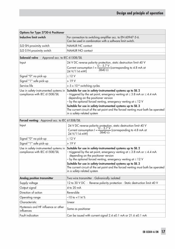
Options for Type 3730-6 Positioner
Inductive limit switch For connection to switching amplifier acc. to EN 60947-5-6.Can be used in combination with a software limit switch.
SJ2-SN proximity switch NAMUR NC contact
SJ2-S1N proximity switch NAMUR NO contact
Solenoid valve · Approval acc. to IEC 61508/SIL
Input 24 V DC reverse polarity protection, static destruction limit 40 V
Current consumption I =U 5.7 V3840�
�(corresponding to 4.8 mA at
24 V/114 mW)
Signal "0" no pick-up � 12 V
Signal "1" safe pick-up > 19 V
Service life > 5 x 10 6 switching cycles
Use in safety-instrumented systems incompliance with IEC 61508/SIL
Suitable for use in safety-instrumented systems up to SIL 2– triggered by the set point, emergency venting at � 3.8 mA or � 4.4 mA
depending on the positioner version– by the optional forced venting, emergency venting at � 12 VSuitable for use in safety-instrumented systems up to SIL 3The current circuit of the set point and the forced venting must both be operatedin a safety-related system
Forced venting· Approval acc. to IEC 61508/SIL
Input 24 V DC reverse polarity protection, static destruction limit 40 VCurrent consumption I =
U 5.7 V3840�
�(corresponding to 4.8 mA at
24 V/114 mW)
Signal "0" no pick-up � 12 V
Signal "1" safe pick-up > 19 V
Use in safety-instrumented systems incompliance with IEC 61508/SIL
Suitable for use in safety-instrumented systems up to SIL 2– triggered by the set point, emergency venting at � 3.8 mA or � 4.4 mA
depending on the positioner version– by the optional forced venting, emergency venting at � 12 VSuitable for use in safety-instrumented systems up to SIL 3The current circuit of the set point and the forced venting must both be operatedin a safety-related system
Analog position transmitter Two-wire transmitter · Galvanically isolated
Supply voltage 12 to 30 V DC · Reverse polarity protection · Static destruction limit 40 V
Output signal 4 to 20 mA
Direction of action Reversible
Operating range –10 to +114 %
Characteristic Linear
Hysteresis and HF influence or otherinfluences Same as positioner
Fault indication Can be issued with current signal 2.4 ±0.1 mA or 21.6 ±0.1 mA
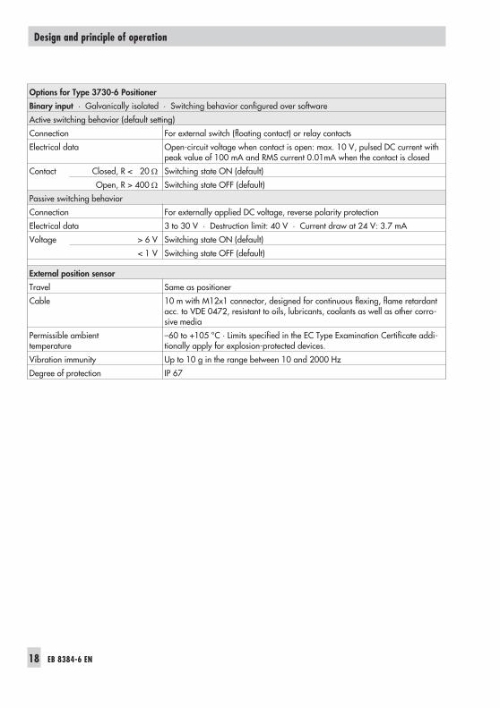
Connection For external switch (floating contact) or relay contacts
Electrical data Open-circuit voltage when contact is open: max. 10 V, pulsed DC current withpeak value of 100 mA and RMS current 0.01mA when the contact is closed
Contact Closed, R < 20 � Switching state ON (default)
Open, R > 400 � Switching state OFF (default)
Passive switching behavior
Connection For externally applied DC voltage, reverse polarity protection
Electrical data 3 to 30 V · Destruction limit: 40 V · Current draw at 24 V: 3.7 mA
Voltage > 6 V Switching state ON (default)
< 1 V Switching state OFF (default)
External position sensor
Travel Same as positioner
Cable 10 m with M12x1 connector, designed for continuous flexing, flame retardantacc. to VDE 0472, resistant to oils, lubricants, coolants as well as other corro-sive media
Permissible ambienttemperature
–60 to +105 °C · Limits specified in the EC Type Examination Certificate addi-tionally apply for explosion-protected devices.
Vibration immunity Up to 10 g in the range between 10 and 2000 Hz
Degree of protection IP 67
EB 8384-6 EN 19
4 Attachment to the controlvalve – Mounting parts andaccessories
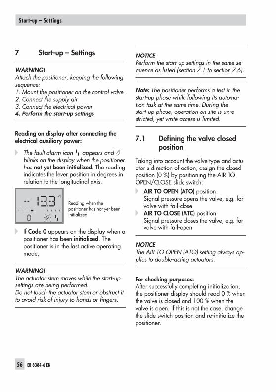
WARNING!Attach the positioner, keeping the followingsequence:1. Mount the positioner on the control valve2. Connect the supply air3. Connect the electrical power4. Perform the start-up settings
The positioner is suitable for the followingtypes of attachment:
� Direct attachment to SAMSONType 3277 Actuator
� Attachment to actuators according toIEC 60534-6 (NAMUR)
� Attachment to Type 3510 Micro-flowValve
� Attachment to rotary actuators
NOTICEAttach the positioner to the control valve,observing the following instructions to avoiddamaging the positioner.– Use only the mounting parts/accessories
listed in the Tables 2 to 6 (pages 41 to43) to mount the positioner. Observe thetype of attachment!
– Observe the assignment between leverand pin position (see travel tables onpage 21)!
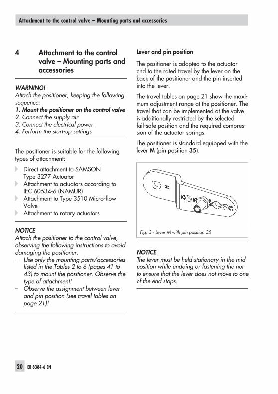
Lever and pin position
The positioner is adapted to the actuatorand to the rated travel by the lever on theback of the positioner and the pin insertedinto the lever.
The travel tables on page 21 show the maxi-mum adjustment range at the positioner. Thetravel that can be implemented at the valveis additionally restricted by the selectedfail-safe position and the required compres-sion of the actuator springs.
The positioner is standard equipped with thelever M (pin position 35).
NOTICEThe lever must be held stationary in the midposition while undoing or fastening the nutto ensure that the lever does not move to oneof the end stops.
20 EB 8384-6 EN
Attachment to the control valve – Mounting parts and accessories
Fig. 3 · Lever M with pin position 35
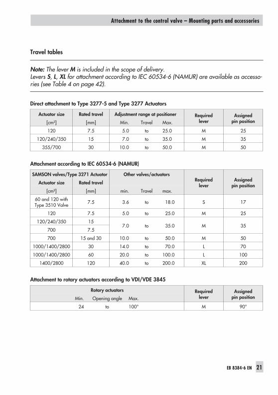
Travel tables
Note: The lever M is included in the scope of delivery.Levers S, L, XL for attachment according to IEC 60534-6 (NAMUR) are available as accesso-ries (see Table 4 on page 42).
Direct attachment to Type 3277-5 and Type 3277 Actuators
Actuator size Rated travel Adjustment range at positioner Requiredlever
Assignedpin position[cm²] [mm] Min. Travel Max.
120 7.5 5.0 to 25.0 M 25
120/240/350 15 7.0 to 35.0 M 35
355/700 30 10.0 to 50.0 M 50
Attachment according to IEC 60534-6 (NAMUR)
SAMSON valves/Type 3271 Actuator Other valves/actuatorsRequired
leverAssigned
pin positionActuator size Rated travel
[cm²] [mm] min. Travel max.
60 and 120 withType 3510 Valve 7.5 3.6 to 18.0 S 17
120 7.5 5.0 to 25.0 M 25
120/240/350 157.0 to 35.0 M 35
700 7.5
700 15 and 30 10.0 to 50.0 M 50
1000/1400/2800 30 14.0 to 70.0 L 70
1000/1400/2800 60 20.0 to 100.0 L 100
1400/2800 120 40.0 to 200.0 XL 200
Attachment to rotary actuators according to VDI/VDE 3845
Rotary actuators Requiredlever
Assignedpin positionMin. Opening angle Max.
24 to 100° M 90°
EB 8384-6 EN 21
Attachment to the control valve – Mounting parts and accessories
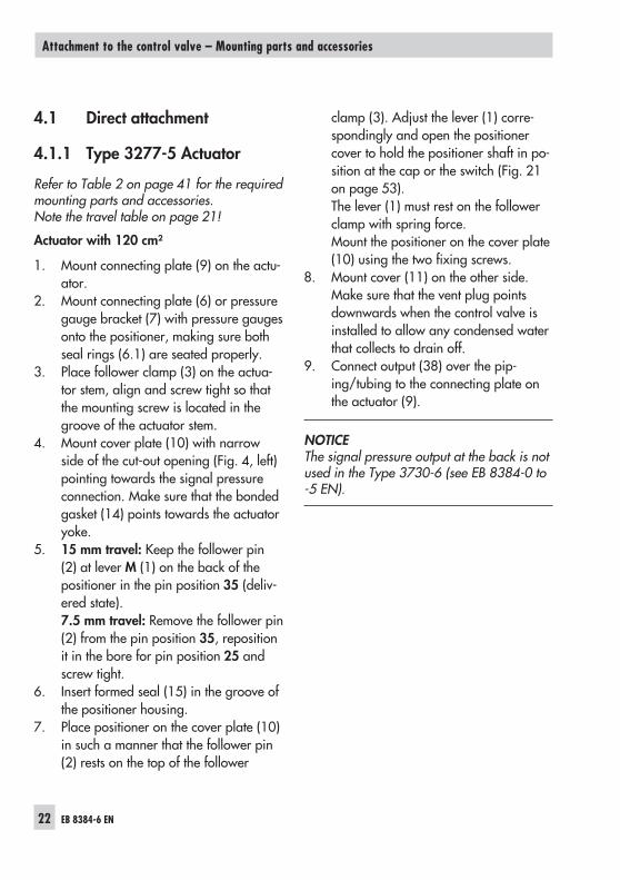
4.1 Direct attachment
4.1.1 Type 3277-5 Actuator
Refer to Table 2 on page 41 for the requiredmounting parts and accessories.Note the travel table on page 21!
Actuator with 120 cm²
1. Mount connecting plate (9) on the actu-ator.
2. Mount connecting plate (6) or pressuregauge bracket (7) with pressure gaugesonto the positioner, making sure bothseal rings (6.1) are seated properly.
3. Place follower clamp (3) on the actua-tor stem, align and screw tight so thatthe mounting screw is located in thegroove of the actuator stem.
4. Mount cover plate (10) with narrowside of the cut-out opening (Fig. 4, left)pointing towards the signal pressureconnection. Make sure that the bondedgasket (14) points towards the actuatoryoke.
5. 15 mm travel: Keep the follower pin(2) at lever M (1) on the back of thepositioner in the pin position 35 (deliv-ered state).7.5 mm travel: Remove the follower pin(2) from the pin position 35, repositionit in the bore for pin position 25 andscrew tight.
6. Insert formed seal (15) in the groove ofthe positioner housing.
7. Place positioner on the cover plate (10)in such a manner that the follower pin(2) rests on the top of the follower
clamp (3). Adjust the lever (1) corre-spondingly and open the positionercover to hold the positioner shaft in po-sition at the cap or the switch (Fig. 21on page 53).The lever (1) must rest on the followerclamp with spring force.Mount the positioner on the cover plate(10) using the two fixing screws.
8. Mount cover (11) on the other side.Make sure that the vent plug pointsdownwards when the control valve isinstalled to allow any condensed waterthat collects to drain off.
9. Connect output (38) over the pip-ing/tubing to the connecting plate onthe actuator (9).
NOTICEThe signal pressure output at the back is notused in the Type 3730-6 (see EB 8384-0 to-5 EN).
22 EB 8384-6 EN
Attachment to the control valve – Mounting parts and accessories
EB 8384-6 EN 23
Attachment to the control valve – Mounting parts and accessories
119
Supply 9 Output 38
56
7
6
10
3
2
1
15
6.1
1.11.2
14
8
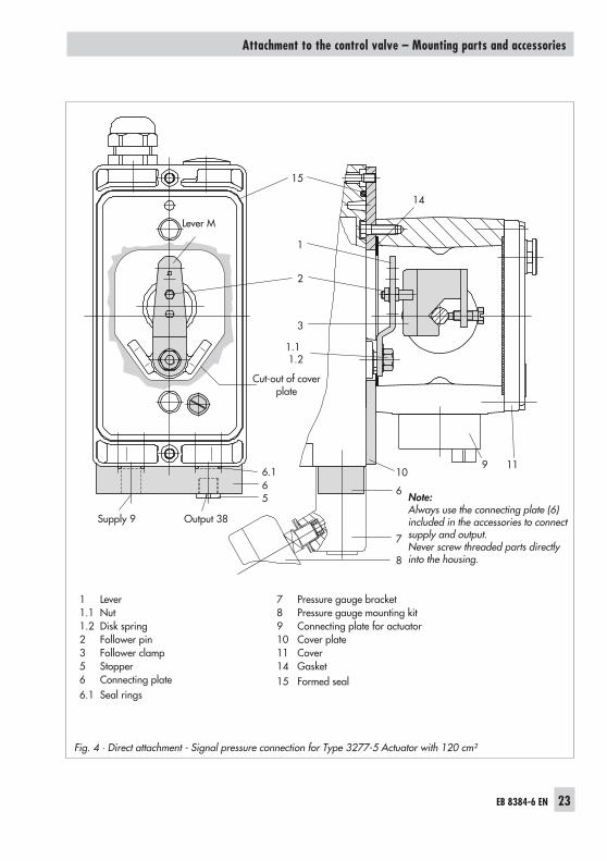
Fig. 4 · Direct attachment - Signal pressure connection for Type 3277-5 Actuator with 120 cm²
1 Lever1.1 Nut1.2 Disk spring2 Follower pin3 Follower clamp5 Stopper6 Connecting plate6.1 Seal rings
7 Pressure gauge bracket8 Pressure gauge mounting kit9 Connecting plate for actuator10 Cover plate11 Cover14 Gasket15 Formed seal
Note:Always use the connecting plate (6)included in the accessories to connectsupply and output.Never screw threaded parts directlyinto the housing.
Cut-out of coverplate
Lever M
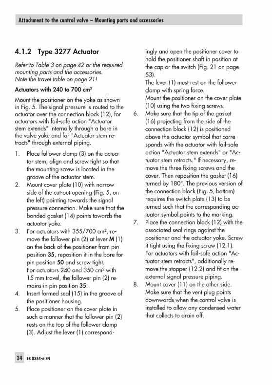
4.1.2 Type 3277 Actuator
Refer to Table 3 on page 42 or the requiredmounting parts and the accessories.Note the travel table on page 21!
Actuators with 240 to 700 cm²
Mount the positioner on the yoke as shownin Fig. 5. The signal pressure is routed to theactuator over the connection block (12), foractuators with fail-safe action "Actuatorstem extends" internally through a bore inthe valve yoke and for "Actuator stem re-tracts" through external piping.
1. Place follower clamp (3) on the actua-tor stem, align and screw tight so thatthe mounting screw is located in thegroove of the actuator stem.
2. Mount cover plate (10) with narrowside of the cut-out opening (Fig. 5, onthe left) pointing towards the signalpressure connection. Make sure that thebonded gasket (14) points towards theactuator yoke.
3. For actuators with 355/700 cm², re-move the follower pin (2) at lever M (1)on the back of the positioner from pinposition 35, reposition it in the bore forpin position 50 and screw tight.For actuators 240 and 350 cm² with15 mm travel, the follower pin (2) re-mains in pin position 35.
4. Insert formed seal (15) in the groove ofthe positioner housing.
5. Place positioner on the cover plate insuch a manner that the follower pin (2)rests on the top of the follower clamp(3). Adjust the lever (1) correspond-
ingly and open the positioner cover tohold the positioner shaft in position atthe cap or the switch (Fig. 21 on page53).The lever (1) must rest on the followerclamp with spring force.Mount the positioner on the cover plate(10) using the two fixing screws.
6. Make sure that the tip of the gasket(16) projecting from the side of theconnection block (12) is positionedabove the actuator symbol that corre-sponds with the actuator with fail-safeaction "Actuator stem extends" or "Ac-tuator stem retracts." If necessary, re-move the three fixing screws and thecover. Then reposition the gasket (16)turned by 180°. The previous version ofthe connection block (Fig. 5, bottom)requires the switch plate (13) to beturned such that the corresponding ac-tuator symbol points to the marking.
7. Place the connection block (12) with theassociated seal rings against thepositioner and the actuator yoke. Screwit tight using the fixing screw (12.1).For actuators with fail-safe action "Ac-tuator stem retracts", additionally re-move the stopper (12.2) and fit on theexternal signal pressure piping.
8. Mount cover (11) on the other side.Make sure that the vent plug pointsdownwards when the control valve isinstalled to allow any condensed waterthat collects to drain off.
24 EB 8384-6 EN
Attachment to the control valve – Mounting parts and accessories
EB 8384-6 EN 25
Attachment to the control valve – Mounting parts and accessories
2
10 1415
1 2 3 11 11.1
SUPPLY
13
B
C
1.11.2
12
12.1
12
12.2
12.11216
16 16
12.2SUPPLY
Ansicht A
Ansicht B
Ansicht C
SUPPLY
G
G 3/8
A
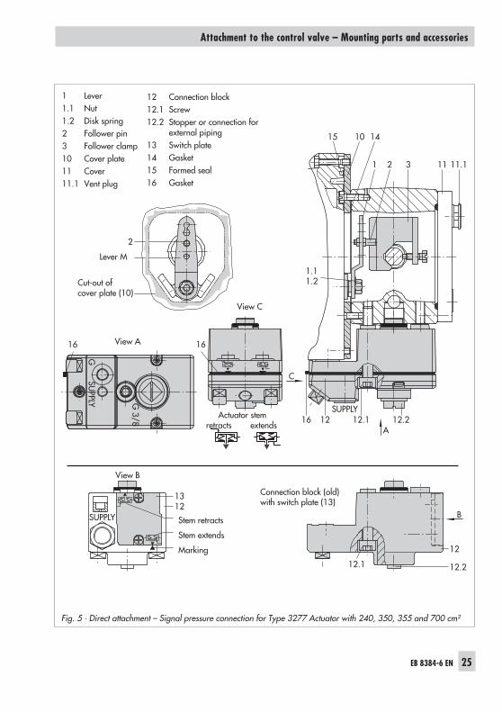
Fig. 5 · Direct attachment – Signal pressure connection for Type 3277 Actuator with 240, 350, 355 and 700 cm²
12 Connection block12.1 Screw12.2 Stopper or connection for
external piping13 Switch plate14 Gasket15 Formed seal16 Gasket
Lever M
Cut-out ofcover plate (10)
Connection block (old)with switch plate (13)
Stem retracts
Stem extends
Marking
View A
View C
View B
Actuator stemretracts extends
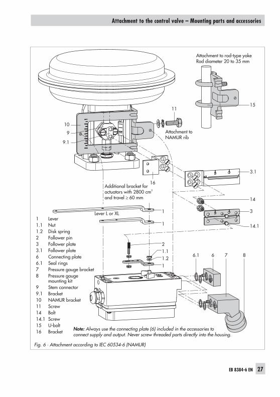
4.2 Attachment according toIEC 60534-6 (NAMUR)
Refer to Table 4 on page 42 for the requiredmounting parts and the accessories.Note the travel table on page 21!
The positioner is attached to the controlvalve with a NAMUR bracket (10).
1. Screw the two bolts (14) to the bracket(9.1) of the stem connector (9), placethe follower plate (3) on top and usethe screws (14.1) to tighten.Actuator size 2800 cm² and 1400 cm²(120 mm travel):– For a travel of 60 mm or smaller,
screw the longer follower plate (3.1)directly to the stem connector (9).
– For a travel exceeding 60 mm,mount the bracket (16) first and thenthe follower plate (3) to the brackettogether with the bolts (14) andscrews (14.1).
2. Mount NAMUR bracket (10) to the con-trol valve as follows:– For attachment to the NAMUR rib,
use an M8 screw (11), washer andtoothed lock washer directly in theexisting yoke bore.
– For attachment to valves withrod-type yokes, use two U-bolts (15)around the yoke.Align the NAMUR bracket (10) insuch a way that the slot of the follo-wer plate (3) is centrally aligned withthe NAMUR bracket at mid valvetravel.
3. Mount connecting plate (6) or pressuregauge bracket (7) with pressure gauges(8) on the positioner, making sure bothseal rings (6.1) are seated properly.
4. Select required lever size (1) M, L or XLand pin position according to the actu-ator size and valve travels listed in thetable on page 21.Should you require a pin position otherthan position 35 with the standard in-stalled lever M, or require a lever size Lor XL, proceed as follows:
NOTICEThe lever must be held stationary in the midposition while undoing or fastening the nutto ensure that the lever does not move to oneof the end stops.
5. Fasten the follower pin (2) in the as-signed lever bore (pin position) as listedin the table. Only use the longer fol-lower pin (2) included in the mountingkit.
6. Place lever (1) on the positioner shaftand screw tight using the disk spring(1.2) and nut (1.1).
7. Place positioner on the NAMURbracket in such a manner that the fol-lower pin (2) rests in the slot of the fol-lower plate (3, 3.1). Adjust the lever (1)correspondingly.Screw the positioner to the NAMURbracket using both fixing screws.
26 EB 8384-6 EN
Attachment to the control valve – Mounting parts and accessories
EB 8384-6 EN 27
Attachment to the control valve – Mounting parts and accessories
10
11
1
1 14.1
3
3.1
16
15
14
11.21.12
9.1
9
6.1 6 7 8
Fig. 6 · Attachment according to IEC 60534-6 (NAMUR)
Attachment toNAMUR rib
Attachment to rod-type yokeRod diameter 20 to 35 mm
Additional bracket foractuators with 2800 cm2
and travel � 60 mm
Lever L or XL1 Lever1.1 Nut1.2 Disk spring2 Follower pin3 Follower plate3.1 Follower plate6 Connecting plate6.1 Seal rings7 Pressure gauge bracket8 Pressure gauge
mounting kit9 Stem connector9.1 Bracket10 NAMUR bracket11 Screw14 Bolt14.1 Screw15 U-bolt16 Bracket Note: Always use the connecting plate (6) included in the accessories to
connect supply and output. Never screw threaded parts directly into the housing.
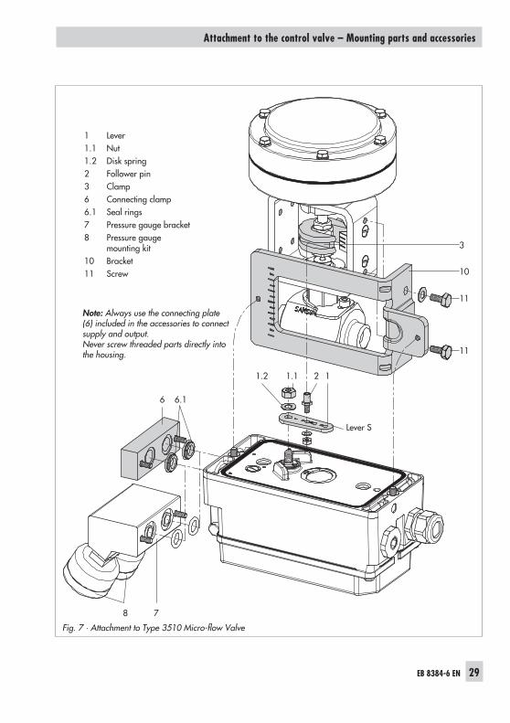
4.3 Attachment to Type 3510Micro-flow Valve withType 3271-5 Actuator
Refer to Table 4 on page 42 for the requiredmounting parts and accessories.Note the travel table on page 21!
The positioner is attached to the valve yokeusing a bracket.
1. Place clamp (3) on the valve stem con-nector, align at a right angle and screwtight.
2. Screw bracket (10) to the valve yokeusing two screws (11).
3. Mount connecting plate (6) or pressuregauge bracket (7) with pressure gaugesto the positioner, making sure both sealrings (6.1) are seated properly.
NOTICEThe lever must be held stationary in the midposition while undoing or fastening the nutto ensure that the lever does not move to oneof the end stops.
4. Unscrew the standard installed lever M(1) including follower pin (2) from thepositioner shaft.
5. Take lever S (1) and screw follower pin(2) in the bore for pin position 17.
6. Place lever S on the positioner shaftand screw tight using the disk spring(1.2) and nut (1.1).
7. Place positioner on the bracket (10) insuch a manner that the follower pinslides into the groove of the clamp (3).
Adjust the lever (1) correspondingly.Screw the positioner to the bracket (10)using both screws.
28 EB 8384-6 EN
Attachment to the control valve – Mounting parts and accessories
EB 8384-6 EN 29
Attachment to the control valve – Mounting parts and accessories
3
10
11
11
6
121.2 1.1
78
6.1
Fig. 7 · Attachment to Type 3510 Micro-flow Valve
1 Lever1.1 Nut1.2 Disk spring2 Follower pin3 Clamp6 Connecting clamp6.1 Seal rings7 Pressure gauge bracket8 Pressure gauge
mounting kit10 Bracket11 Screw
Note: Always use the connecting plate(6) included in the accessories to connectsupply and output.Never screw threaded parts directly intothe housing.
Lever S
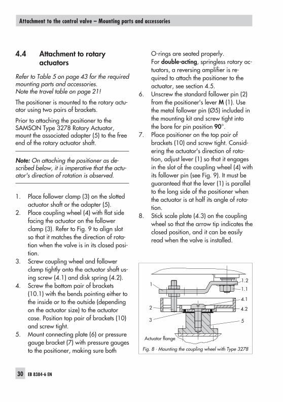
4.4 Attachment to rotaryactuators
Refer to Table 5 on page 43 for the requiredmounting parts and accessories.Note the travel table on page 21!
The positioner is mounted to the rotary actu-ator using two pairs of brackets.
Prior to attaching the positioner to theSAMSON Type 3278 Rotary Actuator,mount the associated adapter (5) to the freeend of the rotary actuator shaft.
Note: On attaching the positioner as de-scribed below, it is imperative that the actu-ator's direction of rotation is observed.
1. Place follower clamp (3) on the slottedactuator shaft or the adapter (5).
2. Place coupling wheel (4) with flat sidefacing the actuator on the followerclamp (3). Refer to Fig. 9 to align slotso that it matches the direction of rota-tion when the valve is in its closed posi-tion.
3. Screw coupling wheel and followerclamp tightly onto the actuator shaft us-ing screw (4.1) and disk spring (4.2).
4. Screw the bottom pair of brackets(10.1) with the bends pointing either tothe inside or to the outside (dependingon the actuator size) to the actuatorcase. Position top pair of brackets (10)and screw tight.
5. Mount connecting plate (6) or pressuregauge bracket (7) with pressure gaugesto the positioner, making sure both
O-rings are seated properly.For double-acting, springless rotary ac-tuators, a reversing amplifier is re-quired to attach the positioner to theactuator, see section 4.5.
6. Unscrew the standard follower pin (2)from the positioner's lever M (1). Usethe metal follower pin (Ø5) included inthe mounting kit and screw tight intothe bore for pin position 90°.
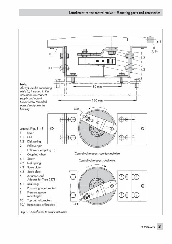
7. Place positioner on the top pair ofbrackets (10) and screw tight. Consid-ering the actuator's direction of rota-tion, adjust lever (1) so that it engagesin the slot of the coupling wheel (4) withits follower pin (see Fig. 9). It must beguaranteed that the lever (1) is parallelto the long side of the positioner whenthe actuator is at half its angle of rota-tion.
8. Stick scale plate (4.3) on the couplingwheel so that the arrow tip indicates theclosed position, and it can be easilyread when the valve is installed.
30 EB 8384-6 EN
Attachment to the control valve – Mounting parts and accessories
1.2
1.11
2
4.1
4.2
53
Fig. 8 · Mounting the coupling wheel with Type 3278
Actuator flange
EB 8384-6 EN 31
Attachment to the control valve – Mounting parts and accessories
10
10.1
6(7, 8)
1.124.3
5
6.1
4
1.21
130 mm
80 mm
Fig. 9 · Attachment to rotary actuators
Slot
Slot
Note:Always use the connectingplate (6) included in theaccessories to connectsupply and output.Never screw threadedparts directly into thehousing.
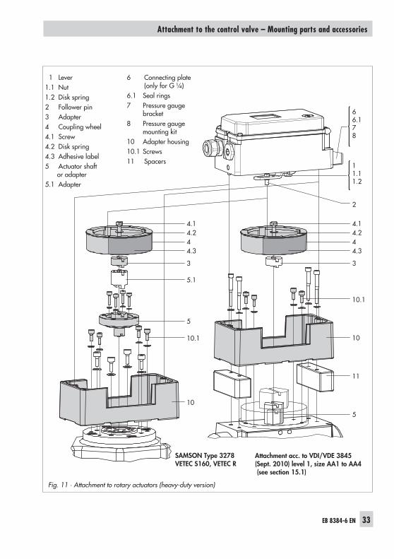
Adapter for Type 32786.1 Seal rings7 Pressure gauge bracket8 Pressure gauge
mounting kit10 Top pair of brackets10.1 Bottom pair of brackets
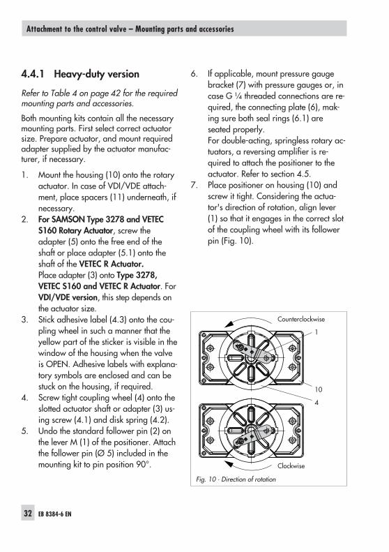
4.4.1 Heavy-duty version
Refer to Table 4 on page 42 for the requiredmounting parts and accessories.
Both mounting kits contain all the necessarymounting parts. First select correct actuatorsize. Prepare actuator, and mount requiredadapter supplied by the actuator manufac-turer, if necessary.
1. Mount the housing (10) onto the rotaryactuator. In case of VDI/VDE attach-ment, place spacers (11) underneath, ifnecessary.
2. For SAMSON Type 3278 and VETECS160 Rotary Actuator, screw theadapter (5) onto the free end of theshaft or place adapter (5.1) onto theshaft of the VETEC R Actuator.Place adapter (3) onto Type 3278,VETEC S160 and VETEC R Actuator. ForVDI/VDE version, this step depends onthe actuator size.
3. Stick adhesive label (4.3) onto the cou-pling wheel in such a manner that theyellow part of the sticker is visible in thewindow of the housing when the valveis OPEN. Adhesive labels with explana-tory symbols are enclosed and can bestuck on the housing, if required.
4. Screw tight coupling wheel (4) onto theslotted actuator shaft or adapter (3) us-ing screw (4.1) and disk spring (4.2).
5. Undo the standard follower pin (2) onthe lever M (1) of the positioner. Attachthe follower pin (Ø 5) included in themounting kit to pin position 90°.
6. If applicable, mount pressure gaugebracket (7) with pressure gauges or, incase G ¼ threaded connections are re-quired, the connecting plate (6), mak-ing sure both seal rings (6.1) areseated properly.For double-acting, springless rotary ac-tuators, a reversing amplifier is re-quired to attach the positioner to theactuator. Refer to section 4.5.
7. Place positioner on housing (10) andscrew it tight. Considering the actua-tor's direction of rotation, align lever(1) so that it engages in the correct slotof the coupling wheel with its followerpin (Fig. 10).
32 EB 8384-6 EN
Attachment to the control valve – Mounting parts and accessories
1
10
4
Fig. 10 · Direction of rotation
Counterclockwise
Clockwise
EB 8384-6 EN 33
Attachment to the control valve – Mounting parts and accessories
66.178
11.11.2
2
4.1
3
10.1
10
11
5
4.344.2
4.1
3
5.1
5
10.1
10
4.344.2
Fig. 11 · Attachment to rotary actuators (heavy-duty version)
1 Lever1.1 Nut1.2 Disk spring2 Follower pin3 Adapter4 Coupling wheel4.1 Screw4.2 Disk spring4.3 Adhesive label5 Actuator shaft
For the use with double-acting actuators, thepositioner must be fitted with a reversingamplifier, e.g. the SAMSON Type 3710 Re-versing Amplifier (see Mounting and Oper-ating Instructions EB 8392 EN).
4.6 Attaching an externalposition sensor
Refer to Table 7 on page 44 for the requiredmounting parts and accessories.
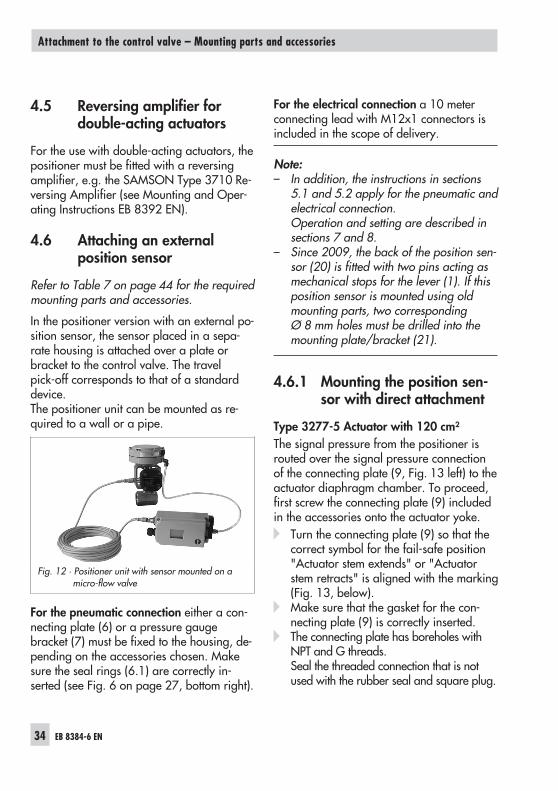
In the positioner version with an external po-sition sensor, the sensor placed in a sepa-rate housing is attached over a plate orbracket to the control valve. The travelpick-off corresponds to that of a standarddevice.The positioner unit can be mounted as re-quired to a wall or a pipe.
For the pneumatic connection either a con-necting plate (6) or a pressure gaugebracket (7) must be fixed to the housing, de-pending on the accessories chosen. Makesure the seal rings (6.1) are correctly in-serted (see Fig. 6 on page 27, bottom right).
For the electrical connection a 10 meterconnecting lead with M12x1 connectors isincluded in the scope of delivery.
Note:– In addition, the instructions in sections
5.1 and 5.2 apply for the pneumatic andelectrical connection.Operation and setting are described insections 7 and 8.
– Since 2009, the back of the position sen-sor (20) is fitted with two pins acting asmechanical stops for the lever (1). If thisposition sensor is mounted using oldmounting parts, two correspondingØ 8 mm holes must be drilled into themounting plate/bracket (21).
4.6.1 Mounting the position sen-sor with direct attachment
Type 3277-5 Actuator with 120 cm²The signal pressure from the positioner isrouted over the signal pressure connectionof the connecting plate (9, Fig. 13 left) to theactuator diaphragm chamber. To proceed,first screw the connecting plate (9) includedin the accessories onto the actuator yoke.� Turn the connecting plate (9) so that the
correct symbol for the fail-safe position"Actuator stem extends" or "Actuatorstem retracts" is aligned with the marking(Fig. 13, below).
� Make sure that the gasket for the con-necting plate (9) is correctly inserted.
� The connecting plate has boreholes withNPT and G threads.Seal the threaded connection that is notused with the rubber seal and square plug.
34 EB 8384-6 EN
Attachment to the control valve – Mounting parts and accessories
Fig. 12 · Positioner unit with sensor mounted on amicro-flow valve
Type 3277 Actuator with 240 to 700 cm²The signal pressure is routed to the connec-tion at the side of the actuator yoke for theversion "Actuator stem extends".For the fail-safe position "Actuator stem re-tracts" the connection on the top diaphragmcase is used. The connection at the side ofthe yoke must be fitted with a venting plug(accessories).
Mounting the position sensor
1. Place the lever (1) on the sensor inmid-position and hold it in place.Unthread the nut (1.1) and remove thelever together with the disk spring (1.2)from the sensor shaft.
2. Screw the position sensor (20) onto themounting plate (21).
3. Depending on the actuator size andrated valve travel, determine the re-quired lever and position of the fol-lower pin (2) from the travel table onpage 21.The positioner is delivered with lever Min pin position 35 on the sensor. If nec-essary, remove the follower pin (2)from its pin position and move it to theborehole for the recommended pin po-sition and screw tight.
4. Place the lever (1) and disk spring (1.2)on the sensor shaft.
EB 8384-6 EN 35
Attachment to the control valve – Mounting parts and accessories
2021
9
11
1.11.2
3
2
1
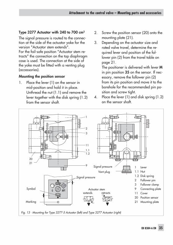
Fig. 13 · Mounting for Type 3277-5 Actuator (left) and Type 3277 Actuator (right)
Signal pressure
Vent plug
Actuator stemextends retracts
Symbol
Marking
Signal pressure
1 Lever1.1 Nut1.2 Disk spring2 Follower pin3 Follower clamp9 Connecting plate11 Cover20 Position sensor21 Mounting plate
Place the lever (1) in mid-position andhold it in place. Screw on the nut (1.1).
5. Place the follower clamp (3) on the ac-tuator stem, align and fasten it, makingsure that the fastening screw rests in thegroove of the actuator stem.
6. Place the mounting plate (21) togetherwith the sensor onto the actuator yokeso that the follower pin (2) rests on thetop of the follower clamp (3). It mustrest on it with spring force.Screw tight the mounting plate (21)onto the actuator yoke using both fixingscrews.
7. Mount cover (11) on the other side.Make sure that the vent plug pointsdownwards when the control valve isinstalled to allow any condensed waterthat collects to drain off.
4.6.2 Mounting the position sen-sor with attachment accord-ing to IEC 60534-6
For the required mounting parts and acces-sories, refer to Table 7 on page 44.
1. Place the lever (1) on the sensor inmid-position and hold it in place.Unthread the nut (1.1) and remove thelever together with the disk spring (1.2)from the sensor shaft.
2. Screw the position sensor (20) onto thebracket (21).
The standard attached lever M with the fol-lower pin (2) at position 35 is designed for120, 240 and 350 cm² actuators with15 mm rated travel.
36 EB 8384-6 EN
Attachment to the control valve – Mounting parts and accessories
20 21
2
1.1, 1.2 14.1 3 14 99.1
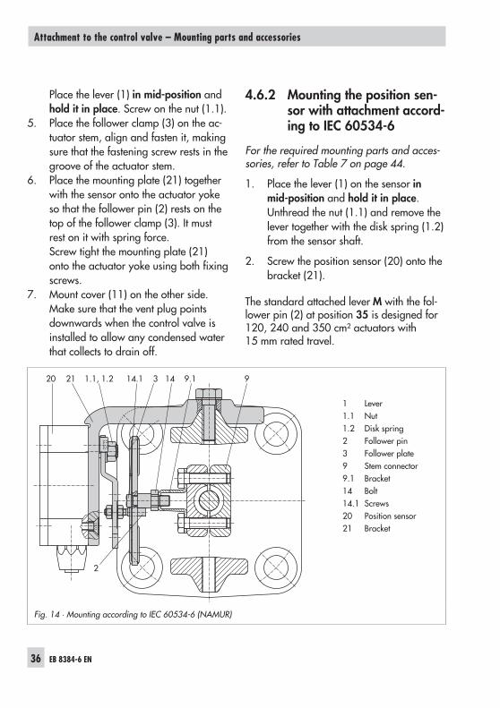
Fig. 14 · Mounting according to IEC 60534-6 (NAMUR)
1 Lever1.1 Nut1.2 Disk spring2 Follower pin3 Follower plate9 Stem connector9.1 Bracket14 Bolt14.1 Screws20 Position sensor21 Bracket
For other actuator sizes or travels, select thelever and pin position from the travel tableon page 21. Lever L and XL are included inthe mounting kit.
3. Place the lever (1) and disk spring (1.2)on the sensor shaft.Place the lever (1) in mid-position andhold it in place. Screw on the nut (1.1).
4. Screw both bolts (14) to the bracket(9.1) of the stem connector (9). Attachthe follower plate (3) and fix with thescrews (14.1).
5. Place the bracket with the sensor at theNAMUR rib in such a manner that thefollower pin (2) rests in the slot of thefollower plate (3), then screw thebracket using its fixing screws onto thevalve.
4.6.3 Mounting the position sen-sor to Type 3510 Mi-cro-flow Valve
For the required mounting parts and acces-sories, refer to Table 7 on page 44.
1. Place the lever (1) in mid-position andhold it in place. Unscrew the nut (1.1)and remove the standard attached leverM (1) together with the disk spring(1.2) from the sensor shaft.
2. Screw the position sensor (20) onto thebracket (21).
3. Select the lever S (1) from the accesso-ries and screw the follower pin (2) intothe hole for pin position 17.Place the lever (1) and disk spring (1.2)on the sensor shaft.
EB 8384-6 EN 37
Attachment to the control valve – Mounting parts and accessories
20 211.11.2
1
3
2
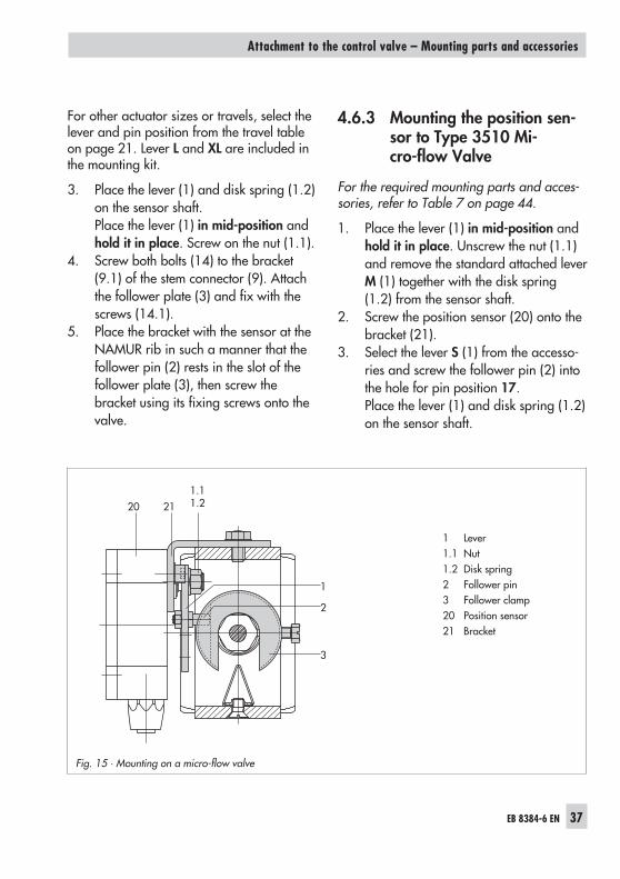
Fig. 15 · Mounting on a micro-flow valve
1 Lever1.1 Nut1.2 Disk spring2 Follower pin3 Follower clamp20 Position sensor21 Bracket
Place the lever (1) in mid-position andhold it in place. Screw on the nut (1.1).
4. Place the follower clamp (3) on the stemconnector, align it at a right angle andscrew tight.
5. Position the bracket (21) with the posi-tion sensor on the valve yoke and screwtight, making sure the follower pin (2)slides into the groove of the followerclamp (3).
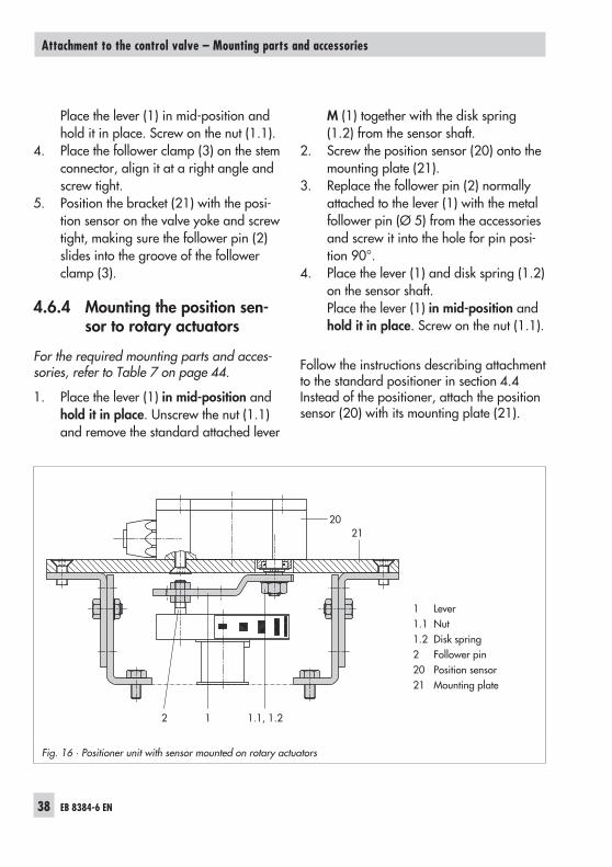
4.6.4 Mounting the position sen-sor to rotary actuators
For the required mounting parts and acces-sories, refer to Table 7 on page 44.
1. Place the lever (1) in mid-position andhold it in place. Unscrew the nut (1.1)and remove the standard attached lever
M (1) together with the disk spring(1.2) from the sensor shaft.
2. Screw the position sensor (20) onto themounting plate (21).
3. Replace the follower pin (2) normallyattached to the lever (1) with the metalfollower pin (Ø 5) from the accessoriesand screw it into the hole for pin posi-tion 90°.
4. Place the lever (1) and disk spring (1.2)on the sensor shaft.Place the lever (1) in mid-position andhold it in place. Screw on the nut (1.1).
Follow the instructions describing attachmentto the standard positioner in section 4.4Instead of the positioner, attach the positionsensor (20) with its mounting plate (21).
38 EB 8384-6 EN
Attachment to the control valve – Mounting parts and accessories
2021
2 1 1.1, 1.2
Fig. 16 · Positioner unit with sensor mounted on rotary actuators
1 Lever1.1 Nut1.2 Disk spring2 Follower pin20 Position sensor21 Mounting plate
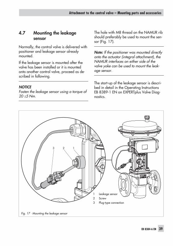
4.7 Mounting the leakagesensor
Normally, the control valve is delivered withpositioner and leakage sensor alreadymounted.
If the leakage sensor is mounted after thevalve has been installed or it is mountedonto another control valve, proceed as de-scribed in following.
NOTICEFasten the leakage sensor using a torque of20 �5 Nm.
The hole with M8 thread on the NAMUR ribshould preferably be used to mount the sen-sor (Fig. 17).
Note: If the positioner was mounted directlyonto the actuator (integral attachment), theNAMUR interfaces on either side of thevalve yoke can be used to mount the leak-age sensor.
The start-up of the leakage sensor is descri-bed in detail in the Operating InstructionsEB 8389-1 EN on EXPERTplus Valve Diag-nostics.
EB 8384-6 EN 39
Attachment to the control valve – Mounting parts and accessories
Positioners with stainless steel housings re-quire mounting parts that are completelymade of stainless steel or free of aluminum.
Note: The pneumatic connecting plate, pres-sure gauge bracket and Type 3710 Pneu-matic Reversing Amplifier are available instainless steel (see Table 6 for order num-bers).
The Tables 2 to 6 (pages 41 to 43) apply forattaching positioners with stainless steelhousings with the following restrictions:� Direct attachment
All mounting kits from Tables 2 and 3can be used. The connection block is notrequired. The stainless steel version of thepneumatic connecting plate routes the airinternally to the actuator.
� Attachment according to IEC 60534-6(NAMUR rib or attachment to rod-typeyokes)All mounting kits from Table 4 can beused. Connecting plate in stainless steel.
� Attachment to rotary actuatorsAll mounting kits from Table 5 can beused except for the heavy-duty version.Connecting plate in stainless steel.
4.9 Air purging function forsingle-acting actuators
The exhaust air from the positioner is di-verted to the actuator spring chamber to
provide corrosion protection inside the actu-ator. The following must be observed:� Direct attachment to Type 3277-5 (stem
extends FA/stem retracts FE)The air purging function is automaticallyprovided.
� Direct attachment to Type 3277, 240 to700 cm2
FA: Remove the stopper 12.2 (Fig. 5on page 25) at the connectionblock and make a pneumatic con-nection to the spring chamber onthe vented side.
NOTICEThe method described does not apply toold connection blocks in powder-paint-coated aluminum.In this case, follow the instructions for at-tachment described below in “Attach-ment acc. to IEC 60534-6 (NAMUR ribor attachment to rod-type yokes) and torotary actuators”.
FE: The air purging function is automa-tically provided.
� Attachment acc. to IEC 60534-6(NAMUR rib or attachment to rod-typeyokes) and to rotary actuatorsThe positioner requires an additionalport for the exhaust air that can be con-nected over piping. An adapter availableas an accessory is used for this purpose.See Table 6.
40 EB 8384-6 EN
Attachment to the control valve – Mounting parts and accessories
NOTICEThe adapter uses one of the M20 x 1.5 con-nections in the housing which means justone cable gland can be installed.
Should other valve accessories be usedwhich vent the actuator (e.g. solenoid valve,volume booster, quick exhaust valve), thisexhaust air must also be included in thepurging function. The connection over theadapter at the positioner must be protectedwith a check valve, e.g. check valve G ¼(order no. 8502-0597) mounted in the pip-ing. Otherwise the pressure in the positionerhousing would rise above the ambient pres-sure and damage the positioner when theexhausting components respond suddenly.
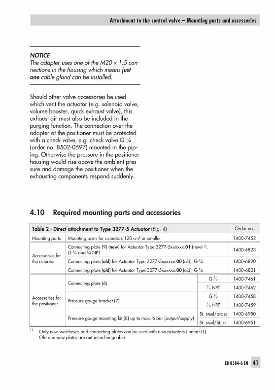
4.10 Required mounting parts and accessories
EB 8384-6 EN 41
Attachment to the control valve – Mounting parts and accessories
Table 2 · Direct attachment to Type 3277-5 Actuator (Fig. 4) Order no.
Mounting parts Mounting parts for actuators 120 cm² or smaller 1400-7452
Accessories forthe actuator
Connecting plate (9) (new) for Actuator Type 3277-5xxxxxx.01 (new) 1),G ¼ and ¼ NPT 1400-6823
Connecting plate (old) for Actuator Type 3277-5xxxxxx.00 (old): G ¼ 1400-6820
Connecting plate (old) for Actuator Type 3277-5xxxxxx.00 (old): G ¼ 1400-6821
Accessories forthe positioner
Connecting plate (6)G 1
4 1400-74611
4 NPT 1400-7462
Pressure gauge bracket (7)G 1
4 1400-74581
4 NPT 1400-7459
Pressure gauge mounting kit (8) up to max. 6 bar (output/supply)St. steel/brass 1400-6950
St. steel/St. st. 1400-69511) Only new switchover and connecting plates can be used with new actuators (Index 01).
Old and new plates are not interchangeable.
42 EB 8384-6 EN
Attachment to the control valve – Mounting parts and accessories
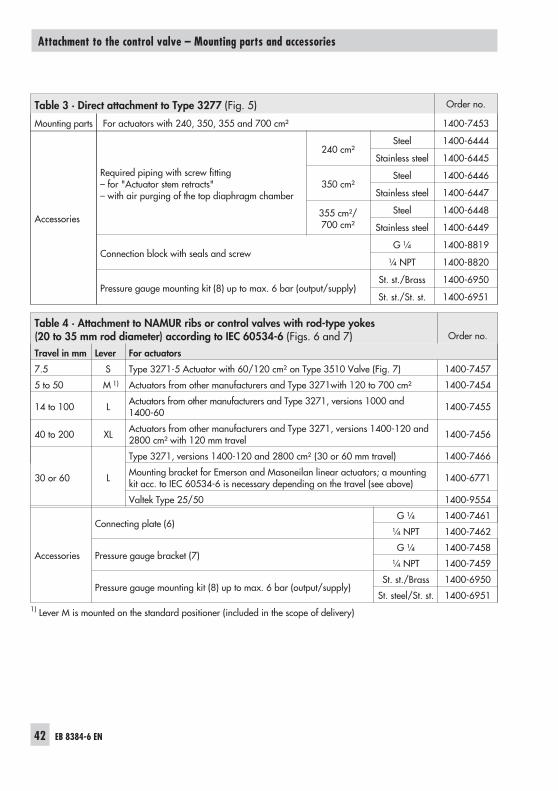
Table 3 · Direct attachment to Type 3277 (Fig. 5) Order no.
Mounting parts For actuators with 240, 350, 355 and 700 cm² 1400-7453
Accessories
Required piping with screw fitting– for "Actuator stem retracts"– with air purging of the top diaphragm chamber
240 cm²Steel 1400-6444
Stainless steel 1400-6445
350 cm²Steel 1400-6446
Stainless steel 1400-6447
355 cm²/700 cm²
Steel 1400-6448
Stainless steel 1400-6449
Connection block with seals and screwG ¼ 1400-8819
¼ NPT 1400-8820
Pressure gauge mounting kit (8) up to max. 6 bar (output/supply)St. st./Brass 1400-6950
St. st./St. st. 1400-6951
Table 4 · Attachment to NAMUR ribs or control valves with rod-type yokes(20 to 35 mm rod diameter) according to IEC 60534-6 (Figs. 6 and 7) Order no.
Travel in mm Lever For actuators
7.5 S Type 3271-5 Actuator with 60/120 cm² on Type 3510 Valve (Fig. 7) 1400-7457
5 to 50 M 1) Actuators from other manufacturers and Type 3271with 120 to 700 cm² 1400-7454
14 to 100 L Actuators from other manufacturers and Type 3271, versions 1000 and1400-60 1400-7455
40 to 200 XL Actuators from other manufacturers and Type 3271, versions 1400-120 and2800 cm² with 120 mm travel 1400-7456
30 or 60 L
Type 3271, versions 1400-120 and 2800 cm² (30 or 60 mm travel) 1400-7466
Mounting bracket for Emerson and Masoneilan linear actuators; a mountingkit acc. to IEC 60534-6 is necessary depending on the travel (see above) 1400-6771
Valtek Type 25/50 1400-9554
Accessories
Connecting plate (6)G ¼ 1400-7461
¼ NPT 1400-7462
Pressure gauge bracket (7)G ¼ 1400-7458
¼ NPT 1400-7459
Pressure gauge mounting kit (8) up to max. 6 bar (output/supply)St. st./Brass 1400-6950
St. steel/St. st. 1400-69511) Lever M is mounted on the standard positioner (included in the scope of delivery)
EB 8384-6 EN 43
Attachment to the control valve – Mounting parts and accessories
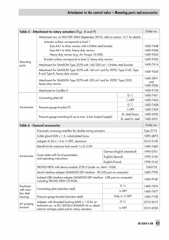
Table 5 · Attachment to rotary actuators (Figs. 8 and 9) Order no.
Mountingparts
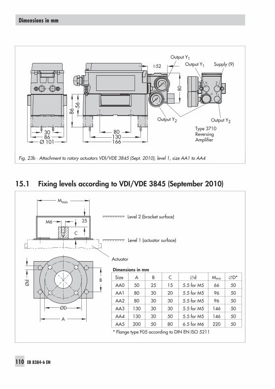
Attachment acc. to VDI/VDE 3845 (September 2010), refer to section 15.1 for details
Actuator surface corresponds to level 1Size AA1 to AA4, version with CrNiMo steel bracketSize AA1 to AA4, heavy-duty versionHeavy-duty version (e.g. Air Torque 10 000)
1400-74481400-92441400-9542
Bracket surface corresponds to level 2, heavy-duty version 1400-9526
Attachment for SAMSON Type 3278 with 160/320 cm², CrNiMo steel bracket 1400-7614
Attachment for SAMSON Type 3278 with 160 cm² and for VETEC Type S160, TypeR and Type R, heavy-duty version
1400-9245
Attachment for SAMSON Type 3278 with 320 cm² and for VETEC Type S320,heavy-duty version
1400-5891and
1400-9526
Attachment to Camflex II 1400-9120
Accessories
Connecting plate (6)G 1
4 1400-74611
4 NPT 1400-7462
Pressure gauge bracket (7)G 1
4 1400-74581
4 NPT 1400-7459
Pressure gauge mounting kit up to max. 6 bar (output/supply)St. steel/brass 1400-6950
St. steel/st. steel 1400-6951
Table 6 · General accessories Order no.
Accessories
Pneumatic reversing amplifier for double-acting actuators Type 3710
Cable gland M20 x 1.5, nickel-plated brass 1890-4875
Adapter M 20 x 1.5 to ½ NPT, aluminum 0310-2149
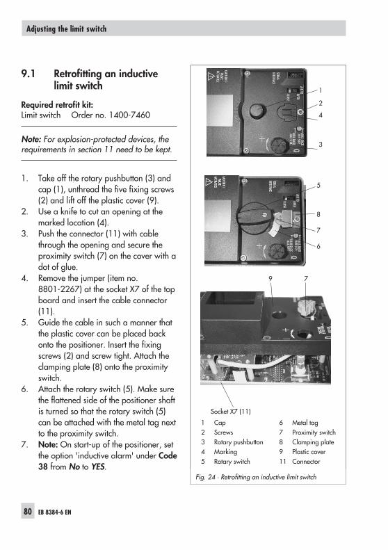
Retrofit kit for inductive limit switch 1x SJ 2-SN 1400-7460
Cover plate with list of parametersand operating instructions
German/English (standard) 1990-0761
English/Spanish 1990-3100
English/French 1990-3142
TROVIS-VIEW with device module 3730-3 (order no. 6661-1056) 1043732
Serial interface adapter (SAMSON SSP interface - RS-232 port on computer) 1400-7700
Isolated USB interface adapter (SAMSON SSP interface - USB port on computer)including TROVIS-VIEW CD-ROM 1400-9740
Positionerwith stain-less steelhousing
Connecting plate (stainless steel)G ¼ 1400-7476
¼ NPT 1400-7477
Pressure gauge bracket (stainless steel) Only in ¼ NPT 1400-7108
Air purgingfunction
Adapter with threaded bushing (M20 x 1.5) for at-tachment acc. to IEC 60534-6 (NAMUR rib or attach-ment to rod-type yoke) and to rotary actuators
G ¼ 0310-2619
¼ NPT 0310-2550
44 EB 8384-6 EN
Attachment to the control valve – Mounting parts and accessories
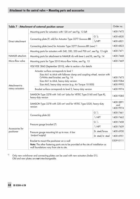
Table 7 · Attachment of external position sensor Order no.
Direct attachment
Mounting parts for actuators with 120 cm² see Fig. 13 left 1400-7472
Connecting plate (9, old) for Actuator Type 3277-5xxxxxx.00G 1
8 1400-6820
18 NPT 1400-6821
Connecting plate (new) for Actuator Type 3277-5xxxxxx.01 (new) 1) 1400-6823
Mounting parts for actuators with 240, 350, 355 and 700 cm², see Fig. 13 right 1400-7471
NAMUR attachmt. Mounting parts for attachment to NAMUR rib with lever L and XL, see Fig. 14 1400-7468
Micro-flow valve Mounting parts for Type 3510 Micro-flow Valve, see Fig. 15 1400-7469
Attachment torotary actuators
VDI/VDE 3845 (September 2010), refer to section x for details
Actuator surface corresponds to level 1Size AA1 to AA4 with follower clamp and coupling wheel, version withCrNiMo steel bracket, see Fig. 16Size AA1 to AA4, heavy-duty versionSize AA5, heavy-duty version (e.g. Air Torque 10 000)
1400-74731400-93841400-9992
Bracket surface corresponds to level 2, heavy-duty version 1400-9974
SAMSON Type 3278 with 160 cm² (also for VETEC Type S160 and Type R),heavy-duty version
1400-9385
SAMSON Type 3278 with 320 cm² and for VETEC Type S320, heavy-dutyversion
1400-5891and
1400-9974
Accessories forpositioner
Connecting plate (6)G 1
4 1400-74611
4 NPT 1400-7462
Pressure gauge bracket (7)G 1
4 1400-74581
4 NPT 1400-7459
Pressure gauge mounting kit up to max. 6 bar(output/supply)
St. steel/brass 1400-6950
St. steel/st. steel 1400-6951
Bracket to mount the positioner on a wallNote: The other fastening parts are to be provided at the site of installation aswall foundations vary from site to site.
0309-0111
1) Only new switchover and connecting plates can be used with new actuators (Index 01).Old and new plates are not interchangeable.
5 Connections
WARNING!Mount the positioner, keeping the followingsequence:1. Mount the positioner on the control valve2. Connect the supply air3. Connect the electrical power4. Perform the start-up settings
The connection of the electrical auxiliarypower may cause the actuator stem to move,depending on the operating mode.Do not touch the actuator stem or obstruct itto avoid risk of injury to hands or fingers.
5.1 Pneumatic connections
NOTICEFollow the instructions below to avoid dama-ging the positioner.– The threaded connections in the
positioner housing are not designed di-rect air connection!
– The screw glands must be screwed intothe connecting plate, the pressure gaugemounting block or the connection blockfrom the accessories.The air connections are optionally de-signed as a bore with ¼ NPT or G ¼thread.The customary fittings for metal and cop-per pipes or plastic hoses can be used.
– The supply air must be dry and free fromoil and dust.The maintenance instructions for up-stream pressure reducing stations mustbe observed.
If the positioner is attached directly to theType 3277 Actuator, the connection of thepositioner's output pressure to the actuator isfixed. For attachment according toIEC 60534-6 (NAMUR), the signal pressurecan be routed to either the top or bottom di-aphragm chamber of the actuator, depend-ing on the actuator's fail-safe action "Actua-tor stem extends" or "Actuator stem re-tracts".For rotary actuators, the manufacturer'sspecifications for connection apply.
5.1.1 Signal pressure gauges
To monitor the supply air (Supply) and sig-nal pressure (Output), we recommend thatpressure gauges be attached (see accesso-ries in Tables 2 to 6).
5.1.2 Supply pressure
The required supply air pressure depends onthe bench range and the actuator's operat-ing direction (fail-safe action).The bench range is registered on the name-plate either as spring range or signal pres-sure range depending on the actuator. Thedirection of action is marked FA or FE, or bya symbol.
Note: If the supply pressure ps is lower thanthe upper spring range value detected dur-ing plotting of the valve signature, PLOW isindicated under Code 0.
EB 8384-6 EN 45
Connections
Actuator stem extends FA (air to open)
Fail-safe position "Valve closed"(for globe and angle valves):
Actuator stem retracts FE (air to close)
Fail-safe position "Valve open"(for globe and angle valves):For tight-closing valves, the maximum signalpressure pstmax is roughly estimated as fol-lows:
pstmax = F + d pA
2
4
� [bar]
d = Seat diameter [cm]�p = Differential pressure across the valve
[bar]A = Actuator diaphragm area [cm²]F = Upper bench range value [bar]
If there are no specifications, calculate asfollows:
Required supply pressure =Upper bench range value + 1 bar.
5.1.3 Signal pressure (output)
The signal pressure at the output (Output38) of the positioner can be limited in stepsof 0.1 bar to a pressure between 1.4 and7.0 bar in Code 16.
The limitations is not activated [7.0 bar] bydefault.
5.2 Electrical connections
DANGER!Risk of electric shock and/orthe formation of an explosiveatmosphere!
– For electrical installation, observe the rel-evant electrotechnical regulations andthe accident prevention regulations thatapply in the country of use.
NOTICE– Adhere to the terminal assignment!– Switching the assignment of the electrical
terminals may cause the explosion pro-tection to become ineffective!
– Do not loosen enameled screws in or onthe housing.
– The maximum permissible values speci-fied in the national EC type examinationcertificates apply when interconnectingintrinsically safe electrical equipment (Uior Uo; Ii or Io; Pi or Po; Ci or Co, and Li orLo).
Selecting cables and wires:For installing intrinsically safe circuits, ob-serve Paragraph 12 in EN 60079-14: 2008(VDE 0165 Part 1).To install and select cables and wires as wellas to run several intrinsically safe circuits inone multi-core cable, observe the installationregulations valid in the country of use. Thediameter of an individual wire in afine-stranded conductor must not be smallerthan 0.1 mm. Protect the conductor endsagainst splicing, e.g. by using wire-end fer-rules.When two separate cables are used for con-
46 EB 8384-6 EN
Connections
nection, an additional cable gland can beinstalled.Seal cable entries left unused with plugs.Devices used at ambient temperatures be-low –20 °C must be fitted with metal cableglands.
Equipment for use in zone 2/zone 22In equipment operated with type of protec-tion EEx nA II (non-sparking equipment) ac-cording to EN 60079-15 (2003), circuitsmay be connected, interrupted or switchedwhile energized only during installation,maintenance or repair.
Equipment connected to energy-limited cir-cuits with type of protection Ex nL (en-ergy-limited equipment) according to EN60079-15 (2003) may be switched undernormal operating conditions.
The maximum permissible values specifiedin the national explosion protection certifi-cates also apply when interconnecting theequipment with energy-limited circuits intype of protection Ex nL IIC/IIB.
Cable entriesThe cable entry with M20 x 1.5 cable gland,6 to 12 mm clamping range.There is a second M20 x 1.5 threaded borein the housing that can be used for addi-tional connection, when required.The screw terminals are designed for wirecross-sections of 0.2 to 2.5 mm². Tighten byat least 0.5 Nm.The wires for the reference variable must beconnected to the terminals 11 and 12 lo-cated in the housing.
Only use a current source!� 3.6 mA: Microprocessor and display active< 3.7 mA: LOW on display� 3.8 mA: Emergency shutdown> 3.9 mA: Actuator can be filled with air> 22 mA: OVERLOAD on displayIn general, it is not necessary to connect thepositioner to a bonding conductor. Shouldthis be required, however, this conductorcan be connected inside the device.Depending on the version, the positioner isequipped with inductive limit switchesand/or a solenoid valve.The position transmitter is operated on atwo-wire circuit. The usual supply voltage is24 V DC. Considering the resistance of thesupply leads, the voltage at the positiontransmitter terminals can be between 12 Vand 30 V DC.Refer to Fig. 18 or the label on the terminalstrip for terminal assignment.
EB 8384-6 EN 47
Connections
Accessories:Plastic cable gland M20 x 1.5:– black Order no. 8808-1011– blue Order no. 8808-1012– Brass, nickel-pl. Order no. 1890-4875– St. steel 1.4305 Order no. 8808-0160
Adapter M20 x 1.5 to ½ NPT– Aluminum, powder-coated
Order no. 0310-2149– Stainless steel Order no. 1400-7114
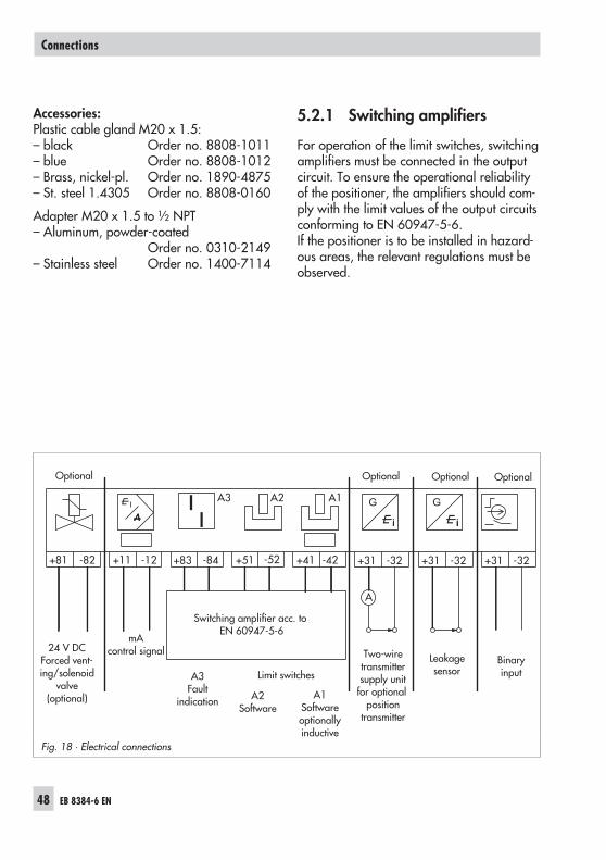
5.2.1 Switching amplifiers
For operation of the limit switches, switchingamplifiers must be connected in the outputcircuit. To ensure the operational reliabilityof the positioner, the amplifiers should com-ply with the limit values of the output circuitsconforming to EN 60947-5-6.If the positioner is to be installed in hazard-ous areas, the relevant regulations must beobserved.
48 EB 8384-6 EN
Connections
G
+81 -82 +11 -12 +83 -84 +51 -52
A2A3 A1
+41 -42 +31 -32
A
+31 -32
G
+31 -32
Fig. 18 · Electrical connections
Optional
Switching amplifier acc. toEN 60947-5-6
24 V DCForced vent-ing/solenoid
valve(optional)
mAcontrol signal
A3Fault
indication
Optional Optional Optional
Binaryinput
Two-wiretransmittersupply unit
for optionalposition
transmitter
Leakagesensor
A2Software
A1Softwareoptionallyinductive
Limit switches
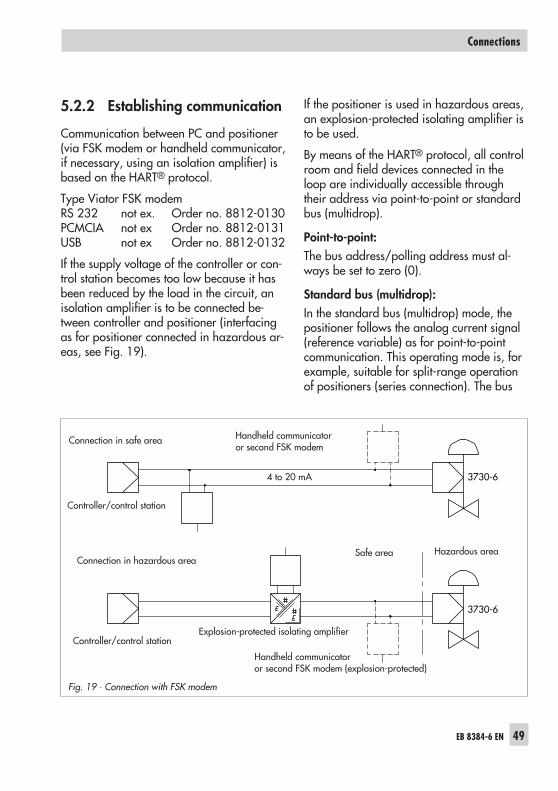
5.2.2 Establishing communication
Communication between PC and positioner(via FSK modem or handheld communicator,if necessary, using an isolation amplifier) isbased on the HART® protocol.
Type Viator FSK modemRS 232 not ex. Order no. 8812-0130PCMCIA not ex Order no. 8812-0131USB not ex Order no. 8812-0132
If the supply voltage of the controller or con-trol station becomes too low because it hasbeen reduced by the load in the circuit, anisolation amplifier is to be connected be-tween controller and positioner (interfacingas for positioner connected in hazardous ar-eas, see Fig. 19).
If the positioner is used in hazardous areas,an explosion-protected isolating amplifier isto be used.
By means of the HART® protocol, all controlroom and field devices connected in theloop are individually accessible throughtheir address via point-to-point or standardbus (multidrop).
Point-to-point:The bus address/polling address must al-ways be set to zero (0).
Standard bus (multidrop):In the standard bus (multidrop) mode, thepositioner follows the analog current signal(reference variable) as for point-to-pointcommunication. This operating mode is, forexample, suitable for split-range operationof positioners (series connection). The bus
EB 8384-6 EN 49
Connections
3730-6
3730-6
Fig. 19 · Connection with FSK modem
Explosion-protected isolating amplifier
Connection in safe area Handheld communicatoror second FSK modem
Handheld communicatoror second FSK modem (explosion-protected)
4 to 20 mA
Safe area Hazardous area
Controller/control station
Controller/control station
Connection in hazardous area
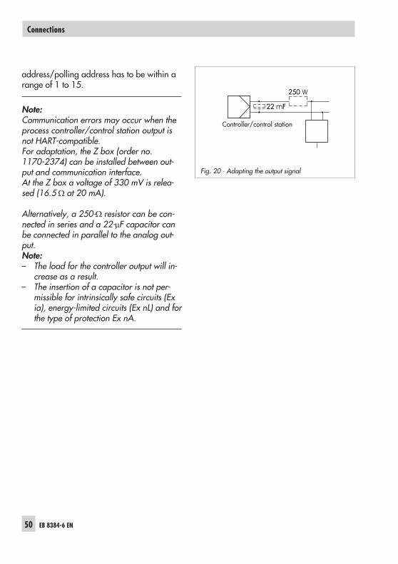
address/polling address has to be within arange of 1 to 15.
Note:Communication errors may occur when theprocess controller/control station output isnot HART-compatible.For adaptation, the Z box (order no.1170-2374) can be installed between out-put and communication interface.At the Z box a voltage of 330 mV is relea-sed (16.5 � at 20 mA).
Alternatively, a 250-� resistor can be con-nected in series and a 22-�F capacitor canbe connected in parallel to the analog out-put.Note:– The load for the controller output will in-
crease as a result.– The insertion of a capacitor is not per-
missible for intrinsically safe circuits (Exia), energy-limited circuits (Ex nL) and forthe type of protection Ex nA.
50 EB 8384-6 EN
Connections
22 mF
250 W
Fig. 20 · Adapting the output signal
Controller/control station
EB 8384-6 EN 51
6 Operator controls andreadings
Rotary pushbutton
The rotary pushbutton is located underneaththe front protective cover.The positioner is operated on site using therotary pushbutton:
Turn to select codes and values.
Press to confirm setting.
Slide switch AIR TO OPEN or AIR TO CLOSE
� AIR TO OPEN applies when the increas-ing signal pressure opens the valve
� AIR TO CLOSE applies when the increas-ing signal pressure closes the valve
The signal pressure is the air pressure at theoutput of the positioner which is transferredto the actuator.For positioners with an attached reversingamplifier for double-acting rotary actuators(section 4.5): switch position AIR TO OPEN.
Volume restriction Q
The volume restriction is used to adapt theair delivery to the actuator size. Two fixedsettings are possible depending on how theair is routed at the actuator:� For actuators smaller than 240 cm² with
a loading pressure connection at the side(Type 3271-5) � MIN SIDE.
� For actuators 240 cm² and larger, selectMAX SIDE for a side connection.
Readings on display
Icons appear on the display that are as-signed to parameters, codes and functions.
Operating mode:– Manual mode (see section 8.2.1)– Automatic mode (see section 8.2.1)
S – SAFE (see section 8.2.2)
� Bar elements:In manual and automatic modes,the bars indicate the system deviationthat depends on the sign (+/–) and thevalue. One bar element appears per 1 %system deviation.If the device has not yet been initialized( blinks on the display), the lever posi-tion in degrees in relation to the longitu-dinal axis is indicated. One bar elementcorresponds to approximately a 5° angleof rotation.If the fifth bar element blinks (reading> 30°), the permissible angle of rotationhas been exceeded. Lever and pin posi-tion must be checked.
� Status messages: Failure: Maintenance required/Maintenance
demandedblinks: Out of specification
These icons indicate that an error has oc-curred.A classified status can be assigned toeach error. Classifications include 'Nomessage', 'Maintenance required','Maintenance demanded' and 'Failure'(see section 14).
� Configuration enabledIndicates that codes marked with an as-terisk (*) in the code list (section 14) areenabled for configuration (section 8.1).
52 EB 8384-6 EN
Operator controls and readings
EB 8384-6 EN 53
Operator controls and readings
AIR TOO
PEN
CLO
SE
INIT
CA
UTIO
NVA
LVE
AC
TUATES
MIN
SIDE
MA
X BAC
K
MIN
BAC
KM
AX SID
E Q
SERIAL
INTERFA
CE
%
Smm
%mm
%
Smm
%mm
Fig. 21 · Display and operator controls
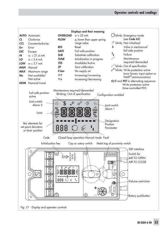
AUTO AutomaticCL ClockwiseCCL CounterclockwiseErr ErrorESC EscapeHI ix � 21.6 mALO ix � 2.4 mALOW w � 3.7 mAMAN ManualMAX Maximum rangeNo Not available/
Not activeNOM Nominal travel
OVERLOAD w > 22 mAPLOW ps lower than upper spring
range valueRES ResetSAFE Fail-safe positionSUB Substitute calibrationTUNE Initialization in progressYES Available/ActiveZP Zero calibration0 bar No supply air�� Increasing/increasing�� Increasing/decreasing
blinks Out of specificationblinks Write protection active
(over binary input option orHART®communication)
O/C and PST in alternating sequence:Write protection active(time-controlled PST)
Displays and their meaning
Limit switchAlarm 1
DesignationPositionParameter
Limit switchAlarm 2
Units
Bar elements forset point deviation
or lever position
Fail-safe positionactive
Maintenance required/demandedBlinking: Out of specification Configuration enabled
Initialization key Cap or rotary switch Metal tag of proximity switch
SSP interface
Switch forAIR TO OPENAIR TO CLOSE
Volume restriction
Rotary pushbutton
Code Closed-loop operation Manual mode Fault
6.1 Serial interface
The positioner must be supplied with at least3.8 mA.
The positioner can be connected directly tothe PC via the local serial interface and theserial interface adapter.The operator software is TROVIS-VIEW 4with installed device module 3730-6.
6.2 HART® communication
The positioner must be supplied with at least3.6 mA. The FSK modem must be connectedin parallel to the current loop.
A DTM file (Device Type Manager) conform-ing to the Specification 1.2 is available forcommunication. This allows the device, forexample, to be run with the PACTware oper-ator interface. All the positioner's parame-ters are then accessible over the DTM andthe operator interface.
For start-up and settings, proceed as de-scribed in section 7.1 to 7.4. Refer to thecode list in section 14 for the parametersnecessary for the operator interface.
NOTICEThe write access for HART® communicationcan be disabled over Code 47. You canonly disable or enable this function locally atthe positioner.The write access is enabled by default. Theon-site operation including the INIT key canbe locked over HART®communication. Theword 'HART' then blinks on the displaywhen Code 3 is selected. This locking func-tion can only be disabled over HART® com-
munication. On-site operation is enabled bydefault.
Note: In the case, complex functions arestarted in the positioner, which require along calculation time or lead to a largequantity of data being stored in the volatilememory of the positioner, the alert 'busy' isissued by the DTM file.This alert is not an error message and cansimply be confirmed.
6.3 Dynamic HART® variables
The HART® specification defines four dy-namic variables consisting of a value and anengineering unit. These variables can be as-signed to device parameters as required.The universal HART® command 3 reads thedynamic variables out of the device. This al-lows manufacturer-specific parameters toalso be transferred using a universal com-mand.
The dynamic variables of Type 3730-6 canbe assigned as follows in TROVIS-VIEW[Device settings > Positioner > HART® com-munication]:
54 EB 8384-6 EN
Operator controls and readings
EB 8384-6 EN 55
Operator controls and readings
Table 8 · Assignment of dynamic HART® variables
Variable Meaning Unit
Set point Set point %
Direction of action set point Direction of action set point %
Set point after transit timespecification
Set point after transit time specification %
Valve position Valve position %
Set point deviation e Set point deviation e %
Absolute total valve travel Absolute total valve travel –
Binary input status 0 = Not active1 = Active255 = –/–
–
Internal solenoidvalve/forced venting status
0 = De-energized1 = Energized2 = Not installed
–
Condensed state 0 = No message1 = Maintenance required2 = Maintenance demanded
3 = Failure4 = Out of specification7 = Function check
–
Temperature Temperature °C
Leakage sensor sound level Sound pressure level (leakage sensor) dB
Ambient pressure Ambient pressure mbar
Signal pressure p out Signal pressure pout bar
Supply pressure Supply pressure bar
Flow rate Flow rate m³/h
Differential pressure Differential pressure bar
7 Start-up – Settings
WARNING!Attach the positioner, keeping the followingsequence:1. Mount the positioner on the control valve2. Connect the supply air3. Connect the electrical power4. Perform the start-up settings
Reading on display after connecting theelectrical auxiliary power:
� The fault alarm icon appears andblinks on the display when the positionerhas not yet been initialized. The readingindicates the lever position in degrees inrelation to the longitudinal axis.
Reading when thepositioner has not yet beeninitialized
� If Code 0 appears on the display when apositioner has been initialized. Thepositioner is in the last active operatingmode.
WARNING!The actuator stem moves while the start-upsettings are being performed.Do not touch the actuator stem or obstruct itto avoid risk of injury to hands or fingers.
NOTICEPerform the start-up settings in the same se-quence as listed (section 7.1 to section 7.6).
Note: The positioner performs a test in thestart-up phase while following its automa-tion task at the same time. During thestart-up phase, operation on site is unre-stricted, yet write access is limited.
7.1 Defining the valve closedposition
Taking into account the valve type and actu-ator's direction of action, assign the closedposition (0 %) by positioning the AIR TOOPEN/CLOSE slide switch:
� AIR TO OPEN (ATO) positionSignal pressure opens the valve, e.g. forvalve with fail-close
� AIR TO CLOSE (ATC) positionSignal pressure closes the valve, e.g. forvalve with fail-open
NOTICEThe AIR TO OPEN (ATO) setting always ap-plies to double-acting actuators.
For checking purposes:After successfully completing initialization,the positioner display should read 0 % whenthe valve is closed and 100 % when thevalve is open. If this is not the case, changethe slide switch position and re-initialize thepositioner.
56 EB 8384-6 EN
Start-up – Settings
Note: The switch position is prompted priorto an initialization. After an initialization hasbeen completed, changing the switch posi-tion does not have any effect on the opera-tion of the positioner.
7.2 Setting the volumerestriction Q
The volume restriction Q is used to adapt theair delivery to the size of the actuator:
� MAX BACK/MIN SIDE position for actu-ators with a transit time < 1 s, e.g. linearactuators with an effective area smallerthan 240 cm², require a restricted airflow rate (MIN).
� MIN BACK/MAX SIDE position for actu-ators with a transit time � 1 s (the airflow rate does not need to be restricted.)
Intermediate positions are not permitted
NOTICEThe positioner needs to be initialized againafter the position of the restriction has beenchanged.
7.3 Adapting the display
The data representation on the positionerdisplay can be turned by 180° to adapt it tohow the positioner is mounted.
Reading direction for rightattachment of pneumaticconnections
Reading direction for left at-tachment of pneumatic con-nections
If the displayed data appear upside down,proceed as follows:
Turn � Code 2
Press , Code 2 blinks
Turn � Required direction
Press to confirm reading direction.
7.4 Limiting the signal pressure
If the maximum actuator force may causedamage to the valve, the signal pressurepout must be limited.
Enable configuration at the positioner beforeactivating the pressure limit function:
Note: If no settings are entered within120 seconds, the enabled configurationfunction becomes invalid.
EB 8384-6 EN 57
Start-up – Settings
MAX BACKMIN SIDE
MIN BACKMAX SIDE
Q
Fig. 22 · Volume restriction QMAX BACK/MIN SIDE setting
Configuration enabledDefault: No
Turn � Code 3, display: No
Press , Code 3 blinks
Turn � YES
Press , display
Limiting the signal pressure:
Pressure limitDefault: No
Turn � Code 16
Press , Code 16 blinks
Turn until the required pressure limit ap-pears.
Press to confirm the pressure limit setting.
7.5 Checking the operatingrange of the positioner
To check the mechanical attachment and theproper functioning, the valve should bemoved through the operating range of thepositioner in the manual operating modewith the manual set point.
Selecting manual operating mode:
Operating modeDefault MAN
Turn � Code 0
Press , Code 0 blinks
Turn � MAN
Press . The positioner changes to themanual operating mode .
Checking the operating range:
Manual set point(current angle of rotation isindicated)
Turn � Code 1
Press , Code 1 and blink
Turn until the pressure in the positionerbuilds up, and the control valve moves to itsfinal positions so that the travel/angle of ro-tation can be checked.The angle of rotation of the lever on theback of the positioner is indicated. A hori-zontal lever (mid position) is equal to 0°.
To ensure the positioner is working prop-erly, the outer bar elements may not blinkwhile the valve is moving through the oper-ating range.Exit Code 1 by pressing the rotarypushbutton ( ).
58 EB 8384-6 EN
Start-up – Settings
WARNING!To avoid personal injury or property dam-age caused by the supply air or electricalauxiliary power, disconnect the supply airand electrical auxiliary power before ex-changing the lever or changing the pin posi-tion.
7.6 Initialization
WARNING!During initialization, the control valve movesthrough its entire travel/angle of rotationrange. Therefore, do not start the initializa-tion procedure while a process is running,but only during start-up when all shut-offvalves are closed.
Before starting initialization, check the maxi-mum permissible signal pressure of the con-trol valve. During initialization, thepositioner issues an output signal pressureup to the maximum supply pressure sup-plied. If necessary, limit the signal pressureby connecting an upstream pressure reduc-ing valve.
NOTICEAfter the positioner has been mounted on toanother actuator or its mounting locationhas been changed and prior tore-initializing the positioner, the positionerneeds to be reset to its basic setting (defaultvalues). Refer to section 7.9.
Note: When the write protection is acti-vated, the initialization cannot be started.
During initialization the positioner adapts it-self optimally to the friction conditions andthe signal pressure demand of the controlvalve. The type and extent of self-adaptationdepends on the set initialization mode:
� Maximum range (MAX) (standardrange)Initialization mode for simple start-up ofvalves with two clearly defined mechani-cal end positions, e.g. three-way valves(see section 7.6.1)
� Nominal range (NOM)Initialization mode for all globe valves(see section 7.6.2)
� Manually selected OPEN position(MAN)Initialization mode for globe valves withmanual entry of the OPEN position (seesection 7.6.3)
� Manually selected end positions(MAN2)Initialization mode for globe valves withmanual entry of both positions (see sec-tion 7.6.4)
� Substitute calibration (SUB)This mode allows a positioner to be re-placed while the plant is running, withthe least amount of disruption to theplant (see section 7.6.5)
Alternating displaysInitialization runningIcon depending on initial-ization mode selected
Bar graph displayindicating the progress ofthe initialization
EB 8384-6 EN 59
Start-up – Settings
After the basic initialization, the referencecurve for the valve signature is recorded(Code 48 - h0 = YES).
Reading in alternatingsequence:TEST/D1
Bar graph displayindicating the progress ofthe initialization
Initialization successful,positioner in automaticoperating mode
The time required for an initialization pro-cess depends on the transit time of the actu-ator and may take several minutes.
After a successful initialization, thepositioner runs in closed-loop operation in-dicated by .
A malfunctioning leads to the process beingcanceled. The initialization error appears onthe display according to how it has beenclassified by the condensed state. See sec-tion 8.3.
Note: An error during the recording of thevalve signature is indicated by Code 81. Thevalve signature does not affect closed-loopoperation.
Valve closed position AIR TO CLOSE
If the slide switch is set to AIR TO CLOSE,the positioner automatically switches to thedirection of action increasing/decreasing(��) on successful completion of initializa-tion.This results in the following assignment be-tween reference variable and valve closedposition:
Valve closedposition
Direction ofaction
Reference variable wValve
CLOSED OPEN
AIR TO OPEN �� w = 0 % w = 100 %
AIR TO CLOSE �� w = 100 % w = 0 %
The tight-closing function is activated.
NOTICESet Code 15 (final position w>) to 99 % forthree-way valves.
Canceling an initialization process
The initialization procedure can be canceledwhile running by pressing the rotarypushbutton ( ). STOP appears three sec-onds long and the positioner then changesto the fail-safe position (SAFE).Exit the fail-safe position again over Code 0(see section 8.2.2).
7.6.1 MAX – Initialization basedon maximum range
The positioner determines travel/angle ofrotation of the closing member from theCLOSED position to the opposite side and
60 EB 8384-6 EN
Start-up – Settings
%
adopts this travel/angle of rotation as theoperating range from 0 to 100 %.
Enable configuration:
Note: If no settings are entered within120 seconds, the enabled configurationfunction becomes invalid.
Default No
Turn � Code 3, display: No
Press , Code 3 blinks
Turn � YES
Press , display
Enter the pin position:
Pin positionDefault No
Turn � Code 4
Press , Code 4 blinks
Turn � Pin position on lever (see relevantsection on attachment)
Press
Turn � Skip nominal range (Code 5) andgo to Code 6.
Select the initialization mode:
Default MAX
Turn � Code 6
Press
Turn � MAX
Press to confirm MAX as the initializationmode.
Start initialization:
� Press INIT key to start initialization!
After initialization, the maximum travel/an-gle of rotation (Code 5) which was detectedduring initialization is indicated.
7.6.2 NOM – Initialization basedon nominal range
The calibrated sensor allows the effectivevalve travel to be set very accurately. Duringthe initialization process, the positionerchecks whether the control valve can movethrough the indicated nominal range (travelor angle) without collision. If this is the case,the indicated nominal range is adopted withthe limits of lower travel/angle range value(Code 8) and upper travel/angle rangevalue (Code 9) as the operating range.
EB 8384-6 EN 61
Start-up – Settings
mm
Enable configuration:
Note: If no settings are entered within120 seconds, the enabled configurationfunction becomes invalid.
Default No
Turn � Code 3, display: No
Press , Code 3 blinks
Turn � YES
Press , display
Enter pin position and nominal range:
Pin positionDefault No
Nominal range(locked with Code 4 = No)
Turn � Code 4
Press , Code 4 blinks
Turn � Pin position on lever (read rele-vant section on attachment)
Press
Turn � Code 5
Press , Code 5 blinks
Turn � Nominal travel/angle
Press
Select the initialization mode:
Initialization modeDefault MAX
Turn � Code 6
Press , Code 6 blinks
Turn � NOM
Press to confirm the NOM as the initial-ization mode.
Start initialization:
� Press INIT key to start initialization!
Note: If the nominal range determined dur-ing initialization is smaller than the rangeentered in Code 5, initialization is canceledand an error message (Code 52) is gener-ated.
After initialization, check the direction ofaction and, if necessary, change it (Code7).
7.6.3 MAN – Initialization basedon a manually selectedOPEN position
Before starting initialization, move the con-trol valve manually to the OPEN position.The positioner calculates the differentialtravel/angle from the OPEN and CLOSED
62 EB 8384-6 EN
Start-up – Settings
mm
mm
positions and adopts it as the operatingrange with limits of lower travel/anglerange value (Code 8) and upper travel/an-gle range value (Code 9).
Enable configuration:
Note: If no settings are entered within120 seconds, the enabled configurationfunction becomes invalid.
Enable configurationDefault No
Turn � Code 3, display: No
Press , Code 3 blinks
Turn � YES
Press , display
Enter the pin position:
Pin positionDefault No
Turn � Code 4
Press , Code 4 blinks
Turn � Pin position on lever (see relevantsection on attachment)
Press
Turn � Skip nominal range (Code 5)and go to Code 6.
Select the initialization mode:
Initialization modeDefault MAX
Turn � Code 6
Press , Code 6 blinks
Turn � MAN
Press to confirm the MAN as the initial-ization mode.
Enter OPEN position:
Manual set point(the current angle of rotationis displayed)
Turn � Code 0
Press , Code 0 blinks
Turn � MAN
Press
Turn � Code 1
Press , Code 1 blinks
Turn clockwise in small steps until the re-quired valve position is reached. The valvemust be moved with a monotonically in-creasing signal pressure.
Press to confirm the OPEN position.
Start initialization:
� Press INIT key to start initialization!
EB 8384-6 EN 63
Start-up – Settings
mm
After initialization, the maximum travel is in-dicated in mm or the maximum angle in ° inCode 5.
Before starting initialization, move the con-trol valve manually to the end positions. Thepositioner calculates the travel/angle differ-ence from the positions that the valve movedto and adopts it as the operating range withlimits of lower travel/angle range value(Code 8) and upper travel/angle rangevalue (Code 9).
Note: This initialization mode can only bestarted when the valve position differs in theend positions and the positioner has not yetbeen initialized.
Enable configuration:
Note: If no settings are entered within120 seconds, the enabled configurationfunction becomes invalid.
Enable configurationDefault No
Turn � Code 3, display: No
Press , Code 3 blinks
Turn � YES
Press , display
Enter the pin position:
Pin positionDefault No
Turn � Code 4
Press , Code 4 blinks
Turn � Pin position on lever (see relevantsection on attachment
Press
Turn � Skip nominal range (Code 5) andgo to Code 6.
Select the initialization mode and enter endpositions:
Initialization modeDefault MAX
POS1 (end position 1)
POS2 (end position 2)
Turn � Code 6
Press , Code 6 blinks
64 EB 8384-6 EN
Start-up – Settings
mm
Turn � MAN2
Press to adopt the initialization modeMAN2 � POS1 and the current angle posi-tion of the lever are indicated on the displayin alternating sequence.
Turn clockwise in small steps until the re-quired valve position is reached. The valvemust be moved with a monotonically in-creasing signal pressure.
Press to confirm the valve position �
WAIT. The valve position is adopted afterthe pressure settles � POS2 and the currentangle position of the lever are indicated onthe display in alternating sequence.
Turn until the required OPEN position ofthe valve is reached.
Press to confirm the valve position �
WAIT. Initialization can be started as soonas MAN2 is indicated again on the display.
Start initialization:
� Press INIT key to start initialization!
After initialization, the tight-closing function(Code 14) is deactivated.
7.6.5 SUB – Substitute calibration
A complete initialization procedure takesseveral minutes and requires the valve tomove through its entire travel range severaltimes. This initialization mode, however, isan emergency mode, in which the controlparameters are estimated and not deter-mined by an initialization procedure. As aresult, a high level of accuracy cannot be
expected. You should always select a differ-ent initialization mode if the plant allows it.
The SUB initialization mode is used to re-place a positioner while the process is run-ning. For this purpose, the control valve isusually fixed mechanically in a certain posi-tion, or pneumatically by means of a pres-sure signal which is routed to the actuatorexternally. The blocking position ensuresthat the plant continues to operate with thisvalve position.The blocking position can also be thefail-safe position when this condition is ben-eficial for the temporary phase.
NOTICEPerform a reset before re-initializing thepositioner if the substitute positioner has al-ready been initialized. Refer to section 7.9.
Enable configuration:
Note: If no settings are entered within120 seconds, the enabled configurationfunction becomes invalid.
Enable configurationDefault No
Turn � Code 3, display: No
Press , Code 3 blinks
Turn � YES
Press , display
EB 8384-6 EN 65
Start-up – Settings
Enter the pin position and nominal range:
Pin positionDefault No
Nominal range(locked with Code 4 = No)
Turn � Code 4
Press , Code 4 blinks
Turn � Pin position on lever (see relevantsection on attachment)
Press
Turn � Code 5
Press , Code 5 blinks
Turn � Nominal travel/angle
Press
Select the initialization mode:
Initialization modeDefault MAX
Turn � Code 6
Press
Turn � SUB
Press to confirm SUB as the initializationmode.
Enter the direction of action:
Direction of actionDefault ��
Turn � Code 7
Press , Code 7 blinks
Turn � Direction of action (��/��)
Press
Deactivate travel limit:
Travel limitDefault 100.0
Turn � Code 11
Press , Code 11 blinks
Turn � No
Press
Change pressure limit and control parame-ters:
Note: Do not change the pressure limit(Code 16). Only change the control param-eters KP (Code 17) and TV (Code 18) if thesettings of the replaced positioner areknown.
66 EB 8384-6 EN
Start-up – Settings
mm
mm
Pressure limitDefault No
KP levelDefault 7
TV levelDefault
Turn � Code 16/17/18
Press , Code 16/17/18 blinks
Turn to set the control parameter selected
Press to confirm the setting.
Enter closing direction and blocking posi-tion:
Closing directionDirection of rotation causingthe valve to move to theCLOSED position (view ontopositioner display)Default: CCL (counterclock-wise)
Blocking positionDefault: 0
Turn � Code 34
Press , Code 34 blinks
Turn � Closing direction (CCL counter-clockwise/CL clockwise)
Press
Turn � Code 35
Press , Code 35 blinks
Turn � Blocking position, e.g. 5 mm(read off at travel indicator scale of theblocked valve or measure with a ruler).
Define the valve closed position:
� Set switch for valve closed position AIRTO OPEN or AIR TO CLOSE as de-scribed in section 7.1 on page 56.
� Set volume restriction as described insection 7.2 on page 57.
Start initialization:
� Press INIT key!The operating mode is changed to auto-matic mode .
Note:– As initialization has not been carried out
completely, the error code 76 (no emer-gency mode) and possibly also errorcode 57 (control loop) may appear onthe display.These alarms do not influence thepositioner’s readiness for operation.
– If the positioner shows a tendency to os-cillate in automatic operating mode, theparameters KP and TV must be slightlycorrected. Proceed as follows:Set TV to 4 (Code 18).If the positioner still oscillates, the gainKP (Code 17) must be decreased until thepositioner shows a stable behavior.
EB 8384-6 EN 67
Start-up – Settings
mm
Zero point calibration
If the process allows it (valve move once tothe closed position), perform a zero pointcalibration according to section 7.7.
7.6.6 Tuning the KP input filter
Changing the KP level (Code 17) affects theset point deviation. This effect can be com-pensated for by tuning the input filter with-out having to re-initialize the positioner.
Enable configuration:
Turn � Code 3, display: No
Press , Code 3 blinks
Turn � YES
Press , display
Tuning the input filter:
Tuning the input filterStandard MAX
Turn � Code 6
Press , Code 6 blinks
Turn � KP
� Press INIT key to start initialization!The tuning is started. During the tuning,the valve moves through its whole rangeand the input filter is recalibrated.
7.7 Zero calibration
In case of discrepancies with the closing po-sition of the valve, e.g. with soft-sealedplugs, it may become necessary torecalibrate the zero point.
NOTICEThe valve briefly moves from the currenttravel/angle position to the closed position.
Note:– The positioner must be connected to the
supply air to perform the zero calibra-tion.
– A zero calibration is not possible if thereis zero point shift of more than 5 %. Inthis case, Code 54 is activated. Thepositioner must be re-initialized.
Enable configuration:
Turn � Code 3, display: No
Press , Code 3 blinks
Turn � YES
Press , display
Perform zero calibration:
Zero calibrationDefault MAX
Turn � Code 6
Press , Code 6 blinks
68 EB 8384-6 EN
Start-up – Settings
Turn � ZP
� Press INIT key!Zero calibration is started, the positionermoves the control valve to the CLOSEDposition and readjusts the internal electri-cal zero point.
7.8 Settings for on/off valves
If the valve is to be operated using theon/off valve as the type of application, theoperating point, test limits and limits for thediscrete analysis must be defined.
Note: The travel range of on/off valves isdefined using the fail-safe position and thegiven Operating point. As a result, the fol-lowing parameters to define the operatingrange and the range of the reference vari-able (set point) cannot be changed or ana-lyzed:Lower travel/angle range value (Code 8)Upper travel/angle range value (Code 9)Lower travel/angle limit (Code 10)Upper travel/angle limit (Code 11)Set point, lower range value (Code 12)Set point, upper range value (Code 13)
Discrete analysis
If the reference variable (w ) is belowOperating point limit (Code 49 - h5) at thestart of automatic operation, the valve( ) moves to the fail-safe position. Ifthe reference variable increases and ex-ceeds the Operating point limit, the valvemoves to the Operating point (Code 49 -h1). The valve moves back to the fail-safeposition if the reference variable continues
and falls below the Fail-safe action limit(Code 49 - h2).
If the reference variable (w ) is abovethe Operating point limit (Code 49 - h5)when automatic mode starts, the valve( ) moves to the Operating point(Code 49 - h1). The valve moves back to thefail-safe position if the reference variablecontinues and falls below the Fail-safe ac-tion limit (Code 49 - h2).
EB 8384-6 EN 69
Start-up – Settings
Δt < 6 s Time [s]
Travel [%]
20
40
60
80
100 Code 49 - h1
Code 49 - h5
Code 49 - h2
Δt < 6 s
20
40
60
80
100
Time [s]
Travel [%]
Code 49 - h1
Code 49 - h5
Code 49 - h2
Triggering the partial stroke test (PST)
A partial stroke test is started when the ref-erence (w ) moves from the Operat-ing point into the range between 25 and50 % travel and remains there for longerthan six seconds. The valve ( ) movesfrom the last defined position to the Lowerrange value (of step) (Code 49 - d2).
After the partial stroke test is completed, thevalve moves back to its previous position(fail-safe position or Operating point).
Canceling the partial stroke test (PST)
The partial stroke test is canceled wheneverthe reference variable changes and falls be-low the Fail-safe action limit. The valvemoves back to fail-safe position.
Enable configuration:
Turn � Code 3, display: No
Press , Code 3 blinks
Turn � YES
Press , display
Select on/off valve as type of application:
Turn � Code 49
Press , Code 49 blinks
Turn � Code h0
Press , Code h0 blinks
Turn � YES
Press
Enter operating point, test limits and limitsfor discrete analysis:
Turn � Code h1/h2/h3/h4/h5
Press , Code h1/h2/h3/h4/h5 blinks
Turn to adjust the parameter selected
Press to confirm the setting.
70 EB 8384-6 EN
Start-up – Settings
20
40
60
80
100
Start PST End PST
Time [s]
Travel [%]
Δt > 6 s
Δt > 6 s
20
40
60
80
100
Start PST End PST
Time [s]
Travel [%]
Code 49 - h1
Code 49 - h1 =Code 49 - d2
Code 49 - h5
Code 49 - h4
Code 49 - h3
Code 49 - h2
Code 49 - d2
Code 49 - h5
Code 49 - h4
Code 49 - h3
Code 49 - h2
7.9 Reset to default values
A reset allows the positioner to be reset tothe default settings. To reset the positioner,the options Diag, Std and DS are availablein Code 36. Table 8 lists the reset functions.
Note: Code 36 – DS is usually selectedwhen the valve is mounted in another posi-tion or when the positioner is to be mountedto another valve.Performing a reset does not necessarilymean the positioner must be re-initialized.
Enable configuration:
Turn � Code 3, display: No
Press , Code 3 blinks
Turn � YES
Press , display
Reset start-up parameters:
ResetDefault No
Turn � Code 36, display: – – –
Press , Code 36 blinks
Turn � DIAG/STD/DS
Press . The parameters are reset depend-ing on the option selected. Refer to Table 9.
EB 8384-6 EN 71
Start-up – Settings
72 EB 8384-6 EN
Start-up – Settings
Table 9 · Reset functions Reset Code 36
Diag Std DS
Initialization NO YES YES
Fail-safe behavior
Air supply failure NO NO YES
Power supply failure of positioner NO NO YES
Power supply failure of external solenoid valve NO NO YES
Emergency mode NO NO NO
Operating hours counter NO NO NO
Device in operation NO YES YES
Device switched on since initialization NO YES YES
Device in operation since initialization NO YES YES
Logging NO YES YES
Codeno. Parameter
2 Reading direction NO YES YES
4 Pin position NO YES YES
5 Nominal range NO YES YES
6 Initialization mode NO YES YES
7 Direction of action NO YES YES
8 Lower travel/angle range value NO YES YES
9 Upper travel/angle range value NO YES YES
10 Lower travel/angle range limit NO YES YES
11 Upper travel/angle range limit NO YES YES
12 Set point, lower range value NO YES YES
13 Set point, upper range value NO YES YES
14 CLOSED end position NO YES YES
15 OPEN end position NO YES YES
16 Pressure limit NO YES YES
17 Proportional-action coefficient Kp level NO NO NO
18 Derivative-action time Tv level NO NO NO
19 Tolerance band NO YES YES
20 Select characteristic NO YES YES
21 Enter transit time OPEN NO YES YES
22 Enter transit time CLOSED NO YES YES
24 Total valve travel limit NO YES YES
25 Alarm mode NO YES YES
EB 8384-6 EN 73
Start-up – Settings
Table 9 · Reset functions Reset Code 36
Diag Std DS
26 Limit A1 NO YES YES
27 Limit A2 NO YES YES
32 Error message in case of 'Function check' condensed state NO YES YES
33 Error message in case of 'Maintenance required' and 'Out ofspecification' condensed state NO YES YES
38 Inductive limit switch NO NO NO
46 Bus address NO NO YES
48 - Diagnosis
d5 Zero point limit
d11 Principle of operation (actuator) NO NO YES
h0 Initialization including valve signature NO YES YES
h3 Desired time until 'Reset diagnostic measured data' NO NO YES
49 - Partial stroke test (PST)
A2 Test start NO NO NO
A3 Enter test interval NO YES YES
A8 Activate �p out monitoring NO YES YES
A9 �p out monitoring value NO YES YES
d2 Lower range value NO YES YES
d3 Upper range value NO YES YES
d4 Activate ramp function NO YES YES
d5 Ramp time (increasing) NO YES YES
d6 Ramp time (decreasing) NO YES YES
d7 Settling time before starting test NO YES YES
d8 Waiting time after step change NO YES YES
d9 Sampling time YES YES YES
E0 Activate x monitoring NO YES YES
E1 x monitoring value NO YES YES
E5 Activate PST tolerance band monitoring NO YES YES
E6 PST tolerance band NO YES YES
E7 Max. test duration YES YES YES
h0 Type of application NO YES YES
h1 Operating point NO YES YES
h2 Fail-safe action limit NO YES YES
h5 Operating point limit NO YES YES
8 Operation
WARNING!The actuator stem moves while the positioneris being operated.Do not touch the actuator stem or obstruct itto avoid risk of injury to hands or fingers.
8.1 Enabling and selectingparameters
The code list in section 14 on page 83 on-wards contains all codes with their meaningand default settings.The codes which are marked with an aster-isk (*) must be enabled with Code 3 beforethe associated parameters can be config-ured as described below.
Code 3Configurationnot enabled
Configurationenabled
Turn � Code 3, display: No
Press , Code 3 blinks.Change the setting of Code 3.
Turn � YES
Press , display:Configuration is enabled.
You can now configure codes one after theother:
Turn and select the required code.
Press to access the selected code. Thecode number starts to blink.
Turn and select the setting.
Press to confirm the selected setting.
Note: If no settings are entered within 120seconds, the enabled configuration functionbecomes invalid and the display changes toCode 0.
Canceling a value before it is confirmed
Canceling the reading
To cancel a value before it is confirmed (bypressing ) proceed as follows:
Turn � ESC
Press . The entered value is not adopted.
74 EB 8384-6 EN
Operation
8.2 Operating modes
8.2.1 Automatic and manual mo-des
After initialization has been completed suc-cessfully, the positioner is in the automaticmode (AUTO).
Automatic mode
Switch to manual operating mode
Turn � Code 0
Press , display: AUTO, Code 0 blinks
Turn � MAN
Press to change to the manual operatingmode .The switchover is smooth since the manualmode starts up with the set point last usedduring automatic mode. The current positionis displayed in %.
Adjust the manual set point
Turn � Code 1
Press , Code 1 blinks
Turn until sufficient pressure has beenbuilt up in the positioner and the controlvalve moves to the required position.
Note: The positioner automatically returns toCode 0 if no settings are made within 120seconds. The positioner remains in the man-ual mode.
Switch to automatic operating mode(AUTO)
Turn � Code 0
Press , Code 0 blinks
Turn � AUTO
Press . The positioner changes to auto-matic operating mode.
EB 8384-6 EN 75
Operation
%
%%
8.2.2 Fail-safe position (SAFE)
If you want to move the valve to fail-safe po-sition determined during start-up (see sec-tion 7.1), proceed as follows:
Turn � Code 0
Press , display: current operating mode(AUTO or MAN), Code 0 blinks
Turn � SAFE
Press , display: SThe valve moves to the fail-safe position.
Once the positioner is initialized, the currentvalve position is indicated on the display in%.
Exit the fail-safe position
Turn � Code 0
Press , Code 0 blinks
Turn and select the required operatingmode AUTO or MAN.
Press .The positioner switches to the operatingmode selected.
8.3 Malfunction/Failure
All status and error messages are classifiedaccording to a status in the positioner. Thedefault settings of the status classification arelisted in the code list.
Note: The status classification can only bechanged in the operator software, e.g.TROVIS-VIEW 4. For more details, refer tothe Operating Instructions EB 8389-1 EN onEXPERTplus Valve Diagnostics.
To provide a better overview, the classifiedmessages are summarized in a condensedstate. The following status messages areavailable:
� FailureThe positioner cannot perform its controltask due to a functional fault in the de-vice or in one of its peripherals or an ini-tialization has not yet been successfullycompleted.
� Maintenance requiredThe positioner still performs its controltask (with restrictions). A maintenancerequirement or above average wear hasbeen determined. The wear tolerance willsoon be exhausted or is reducing at afaster rate than expected. Maintenance isnecessary in the medium term.
� Maintenance demandedThe positioner still performs its controltask (with restrictions). A maintenancedemand or above average wear hasbeen determined. The wear tolerance willsoon be exhausted or is reducing at afaster rate than expected. Maintenance isnecessary in the short term.
76 EB 8384-6 EN
Operation
� Out of specificationThe positioner is operated outside thespecified operating conditions.
Note: If an event is assigned to the 'No mes-sage' status, this event does not have any ef-fect on the condensed state.
Condensed state
The condensed state appears on the displaywith the following icons:
Condensed state Positionerdisplay Priority
Function checkText, e.g. TUNE orTEST
Failure
Out of specifica-tion blinking
Maintenance re-quired/ Mainte-nance demanded
The message with the highest priority deter-mines the condensed state in the positioner.If error messages exist, the possible sourceof error is displayed in Code 49 onwards. Inthis case, ERR appears on the display.
Example:Error caused by pinposition
The cause and recommended action arelisted in the code list (section 14).
Fault alarm output
The 'Failure' as the condensed state causesthe optional fault alarm output to beswitched.
� The 'Function check' condensed state canalso activate the fault alarm contact inCode 32.
� The 'Maintenance required/ Mainte-nance demanded' condensed state and'Out of specification' can also activatethe fault alarm contact in Code 33.
8.3.1 Confirming error messages
Enable configuration:
Note: If no settings are entered within120 seconds, the enabled configurationfunction becomes invalid.
Turn � Code 3, display: No
Press , Code 3 blinks
Turn � YES
Press , display:
Confirm error messages:
Turn � Error code which you want toconfirm.
Press to confirm the error message.
EB 8384-6 EN 77
Operation
S
9 Adjusting the limit switch
The positioner version with inductive limitswitch has one adjustable tag (1) mountedon the shaft which operates the proximityswitch (3).
For operation of the inductive limit switch,the corresponding switching amplifier ac-cording to EN 60947-5-6 (see section5.2.1) must be connected to the output.
If the tag (1) is inside the field of the switch,the switch assumes a high resistance. If thetag is outside of the field, the switch assumesa low resistance.
Normally, the limit switch is adjusted suchthat it will provide a signal in both end posi-tions of the valve. The switch, however, canalso be adjusted to indicate intermediatevalve positions.
Note: The inductive limit switch replaces thesoftware limit switch A1 with terminal as-signment +41/–42.Each switching position can optionally be setto indicate when the tag has entered thefield, or when it has left the field.The second software limit switch remains ef-fective, the function of the software limitswitch A1 is disabled.
Software adaptation
Code 38 (inductive alarm is set to YES).The inductive limit switch is connected to theterminals +41/–42.The device is set up accordingly in the deliv-ered state.
78 EB 8384-6 EN
Adjusting the limit switch
Fig. 23 · Adjustment of the limit switch
Adjustment screw (2) Tag (1) Proximity switch (3)
Setting the switching point:
NOTICEDuring adjustment or testing, the switchingpoint must always be approached frommid-position (50 %).
To ensure safe switching under any ambientconditions, the switching point should be ad-justed to a value of approx. 5 % before themechanical stop (OPEN – CLOSED).
For CLOSED position:
1. Initialize positioner.2. Use the MAN function to move the
positioner to 5 % (see LC display).3. Adjust the tag using the yellow adjust-
ment screw (2) until the tag enters orleaves the field and the switching am-plifier responds. You can measure theswitching voltage as an indicator.
Contact function:
� Tag leaving the field > contact is made� Tag entering the field > contact is
opened.
For OPEN position:
1. Initialize positioner.2. Use the MAN function to move the
positioner to 95 % (see LC display).3. Adjust the tag (1) using the yellow ad-
justment screw (2) until the tag enters orleaves the field of the proximity switch(3).You can measure the switching voltageas an indicator.
Contact function:
� Tag leaving the field > Contact is made.� Tag entering the field > Contact is
opened.
EB 8384-6 EN 79
Adjusting the limit switch
9.1 Retrofitting an inductivelimit switch
Required retrofit kit:Limit switch Order no. 1400-7460
Note: For explosion-protected devices, therequirements in section 11 need to be kept.
1. Take off the rotary pushbutton (3) andcap (1), unthread the five fixing screws(2) and lift off the plastic cover (9).
2. Use a knife to cut an opening at themarked location (4).
3. Push the connector (11) with cablethrough the opening and secure theproximity switch (7) on the cover with adot of glue.
4. Remove the jumper (item no.8801-2267) at the socket X7 of the topboard and insert the cable connector(11).
5. Guide the cable in such a manner thatthe plastic cover can be placed backonto the positioner. Insert the fixingscrews (2) and screw tight. Attach theclamping plate (8) onto the proximityswitch.
6. Attach the rotary switch (5). Make surethe flattened side of the positioner shaftis turned so that the rotary switch (5)can be attached with the metal tag nextto the proximity switch.
7. Note: On start-up of the positioner, setthe option 'inductive alarm' under Code38 from No to YES.
6 Metal tag7 Proximity switch8 Clamping plate9 Plastic cover11 Connector
Fig. 24 · Retrofitting an inductive limit switch
1
2
4
3
10 Maintenance
The positioner does not require any mainte-nance.
There are filters with a 100 µm mesh size inthe pneumatic connections for supply andoutput which can be removed and cleaned,if required.
The maintenance instructions of any up-stream supply air pressure reducing stationsmust be observed.
11 Servicingexplosion-protected devices
If a part of the device on which the explo-sion protection is based needs to be ser-viced, the device must not be put back intooperation until a qualified inspector has as-sessed it according to explosion protectionrequirements, has issued an inspection cer-tificate or given the device a mark of confor-mity.
Inspection by a qualified inspector is not re-quired if the manufacturer performs a rou-tine test on the device prior to putting it backinto operation. The passing of the routinetest must be documented by attaching amark of conformity to the device. Replaceexplosion-protected components only byoriginal, routine-tested components from themanufacturer.
Devices that have already been in opera-tion outside hazardous areas and are in-
tended for future use inside hazardous ar-eas must comply with the safety require-ments placed on serviced devices. Beforebeing used inside hazardous areas, test thedevices according to the specifications forservicing explosion-protected devices.
Refer to section 13 for maintenance, calibra-tion and settings within and outside poten-tially explosive areas.
12 Firmware update (serialinterface)
Firmware updates on positioners currently inoperation can be performed as follows:
When updates are performed by a serviceemployee appointed by SAMSON, the up-date is confirmed on the positioner by thetest mark assigned by SAMSON’s QualityAssurance.
In all other cases, only persons from theplant operator with written approval mayperform updates. This person must confirmthe update on the positioner.
Laptops and PCs connected to the powersupply must use an additional safety barrier.
This does not apply to laptops in battery op-eration. In this case, it is assumed that a bat-tery-powered laptop runs briefly for soft-ware programming or for testing purposes.
a) Updates outside hazardous area:
Remove the positioners from the plantand update them outside the hazardousarea.
EB 8384-6 EN 81
Maintenance
b.) Updates on site:
Updates on site are only permitted afterthe plant operator has presented a sig-ned hot work permit.
After updating has been completed, add thecurrent firmware to the nameplate; this canbe done using labels.
13 Maintenance, calibrationand work on equipment
The interconnection with intrinsically safecircuits to check or calibrate the apparatusmust only be performed with intrinsicallysafe current/voltage calibrators and mea-suring instruments to rule out any damageto components relevant for explosion pro-tection.
The maximum values for intrinsically safecircuits specified in the approvals must bekept.
Switchover from automatic to manual mode is smooth.Automatic mode is only possible after the positioner has been ini-tialized.Refer to section 6 for reading under Code 0
1 Manual set point (manual w)0 to 100 [0] %of the nominal rangeAn on/off valve can bemoved past 100 % of thenominal range (with theclosed position for ATO) orbelow 0 % of the nominalrange (with the closed posi-tion for ATC).
Adjust the manual set point with the rotary pushbutton, thecurrent travel/angle is displayed in % when the positioner is ini-tialized, otherwise the position of the lever in relation to the cen-tral axis is indicated in degrees °.Note: Can only be selected when Code 0 = MAN
2 Reading directionNormal or upside downESC
The reading direction of the positioner display, depending on thelocation of the pneumatic connection
3 Enable configuration[No] · YES · ESC
Enables the option to modify data (automatically deactivated whenthe rotary pushbutton has not been operated for 120 s.)Codes marked with an asterisk (*) can only be read and notoverwritten.HART blinks on the display when the on-site operation is lockedover HART® communication.PST appears on the display when the on-site operation is lockedby the time-controlled partial stroke test.In these cases, codes can only read over the SSP interface.
Note: Codes with marked with an asterisk (*) must be enabled with Code 3 prior to configuration.
4* Pin position[No] · 17, 25, 35, 50, 70,100, 200 mm · 90° with ro-tary actuators · 300 mm withpiston actuators · ESCNOTICE If you select a pinposition in Code 4 that is toosmall, the positioner switchesto SAFE mode for reasons ofsafety
The follower pin must be inserted into the correct pin position ac-cording to the valve travel/angle of rotation.For initialization using NOM (nominal range) or SUB (substitutecalibration), the pin position must be entered.For initialization using MAX, MAN and MAN2, the pin positionis not required, however, it is required under Code 5 to displaythe nominal range.
Pin position Default Adjustment rangeCode 4 Code 5 Code 517 7.5 3.6 to 17.725 7.5 5.0 to 25.035 15.0 7.0 to 35.450 30.0 10.0 to 50.070 40.0 14.0 to 70.7100 60.0 20.0 to 100.0200 120.0 40.0 to 200.090° 90.0 24.0 to 100.0300 200.0 60.0 to 300.0
5* Nominal range[15.0] mm or angle °ESC
For initialization using NOM (nominal range) or SUB (substitutecalibration), the nominal range must be entered. The possible ad-justment range depends on the pin position from the table forCode 4.After initialization to the maximum range (MAX), the maximumnominal travel/angle reached on initialization is displayed.
MAX: Maximum range · For simple start-up of valves with twoclearly defined mechanical end positions · The positionerdetermines travel/angle of rotation of the closingmember from the CLOSED position to the opposite stopin the actuator
NOM: Nominal range · For all globe valves · The positioner de-termines travel/angle of rotation of the closing memberfrom the CLOSED position to the specified nominalrange
MAN: Manual setting 1 · For all globe valves with unknownnominal range (OPEN position) · The positioner deter-mines travel/angle of rotation from the manually se-lected OPEN position (100 %) to the CLOSED position
Note: Codes with marked with an asterisk (*) must be enabled with Code 3 prior to configuration.
6* Initialization mode (initmode)- continued -
MAN2: Manual setting 2 · For all globe valves with unknownnominal range (OPEN and CLOSED position) · Thepositioner determines travel/angle of rotation betweenthe manually selected OPEN (100 %) and the manuallyselected CLOSED position (0 %)
SUB: Substitute calibration · To replace a positioner while theplant is running, with the least amount of disruption tothe plant
KP: Fine tuning of the input filter · The valve moves throughits entire valve range.
NP: Zero calibration · The zero point is recalibrated.NOTICE The valve moves briefly from the operating pointto the closed position!
7* Direction of action (w/x)[��] · �� · ESC
Direction of action of the set point in relation to the valve position��: Increasing/increasing: a globe valve opens as the set
point increases.��: Increasing/decreasing: a globe valve closes as the set
point increases.The direction of action is adapted to the change in closed direc-tion as follows:ATO: AIR TO OPEN · After initialization, the direction of ac-
tion remains increasing/increasing (��), a globe valveopens as the mA signal increases.
ATC: AIR TO CLOSE · After initialization, the direction of ac-tion changes to increasing/decreasing (�� ), a globevalve opens as the mA signal increases.
8* Lower travel/angle rangevalue (lower x-range value)[0.0] to 80.0 % of the nom-inal range · ESCSpecified in mm or angle°,provided Code 4 is acti-vated.
Lower range value for the travel/angle of rotation in the oper-ating range.Nominal range and characteristic are automatically adapted.The operating range is the actual travel/angle of the valve and islimited by the lower travel/angle range value (Code 8) and theupper travel/angle range value (Code 9).Usually, the operating range and the nominal range are iden-tical. The nominal range can be limited to the operating rangeby the lower and upper x-range values. Value is displayed ormust be entered.See also the example in Code 9!
Note: Codes with marked with an asterisk (*) must be enabled with Code 3 prior to configuration.
9* Upper travel/angle rangevalue (upper x-range value)20.0 to [100.0] % of thenominal range · ESCSpecified in mm or angle°,provided Code 4 is acti-vated.
Upper range value for the travel/angle of rotation in the oper-ating range.Nominal range and characteristic are automatically adapted.Example: The operating range is modified, for example, to limitthe range of a valve which has been sized too large. For thisfunction, the entire resolution range of the set point is convertedto the new limits. 0 % on the display corresponds to the adjustedlower limit and 100 % to the adjusted upper limit.
10* Lower travel/angle limit(lower x-limit)[No] · 0.0 to 49.9 % of theoperating range · ESC
Lower limitation of the travel/angle of rotation to the enteredvalue.The characteristic is not adapted.
11* Upper travel/angle limit(upper x-limit)No · 50.0 to120.0 % of theoperating range · ESC,[100.0]
Upper limitation of the travel/angle of rotation to the enteredvalue.The characteristic is not adapted.Example: In some applications, it is better to limit the valvetravel, e.g. if a certain minimum medium flow is required or amaximum flow must not be reached.The lower limit must be adjusted with Code 10 and the upperlimit with Code 11.If a tight-closing function has been set up, it has priority over thetravel limitation!When set to 'No', the valve can be opened past the nominaltravel with a set point outside of the 4 to 20 mA range.
Note: Codes with marked with an asterisk (*) must be enabled with Code 3 prior to configuration.
12* Set point, lower range value(w-start)[0.0] to 75.0 % · ESC
Lower range value (0 % = 4 mA) of the valid set point rangeThis value must be smaller than the upper range value (w-end).The set point range is the difference between Set point, upperrange value – Set point, lower range value. The difference mustbe larger or equal to 25 % (= 4 mA).When the set point range of 0 to 100 % = 4 to 20 mA, the valvemoves through its entire operating range from 0 to 100 %travel/angle of rotation.In split-range operation, the valves operate with smaller setpoints. The control signal of the control unit to control two valvesis divided such, for instance, that the valves move through theirfull travel/angle of rotation at only half the input signal (firstvalve set to 0 to 50 % = 4 to 12 mA and second valve set to 50to 100 % =12 to 20 mA).
13* Set point, upper rangevalue (w-end)25.0 to [100.0] % · ESC
Upper range value (100 % = 20 mA) of the valid set point rangeThis value must be greater than the lower range value (w-start).
14* CLOSED end position(end position w <)No · 0.0 to 49.9 % of thespan set over Code 12/13ESC, [1.0]
Limit of the set point wWhen the set point falls below the limit, an actuator with ATO iscompletely vented and an actuator with ATC is filled with air.This action always lead to the tight-closing of the valve.Codes 14/15 have priority over Codes 8/9/10/11.Codes 21/22 have priority over Codes 14/15.
15* OPEN end position(end position w >)[No] · 50.0 to 100.0 % ofthe span set over Code12/13 · ESCNOTICE For double-actingactuators (ATO) the pres-sure limit must not be active!
Limit of the set point wWhen the set point falls below the limit, an actuator with ATO isfilled with air and an actuator with ATC is completely vented.This action always lead to the maximum opening of the valve.Codes 14/15 have priority over Codes 8/9/10/11.Codes 21/22 have priority over Codes 14/15.Example: Set the end position w > to 99 % for three-way valves.
16* Pressure limit[No] · 1.4 to 7.0 bar · ESC
The signal pressure to the actuator can be limited.After changing the pressure limit setting, the actuator must bevented once (e.g. by selecting the fail-safe position).
Note: Codes with marked with an asterisk (*) must be enabled with Code 3 prior to configuration.
17* Proportional-actioncoefficient Kp level0 to 17 · ESC, [7]NOTICE Changing the KPlevel influences the systemdeviation. This influence canbe balanced out by tuningthe input filter in Code 6.See section 7.6.6.
During the initialization of the positioner, the KP and TV valuesare optimized. If the value for the KP level is below 3, the errorcode 61 is activated.Should the positioner show a tendency for impermissibly highpost-pulse oscillation due to additional interference, the KP andTV levels can be adapted after the initialization.For this, either the TV level can be increased in increments untilthe desired response behavior is reached or, when the maximumvalue of 4 is reached, the KP level can be decreased in incre-ments.
18* Derivative-action time TvlevelNo · 1 to 4 · ESC, [2]
See Code 19.A change of the TV level has no effect on the set point deviation.
19* Tolerance band0.1 to 10.0 % of theoperating range · ESC, [5.0]
Used for error monitoring.If the system deviation is greater than selected tolerance band fora time longer than the lag time [30 s], this causes the error code57 (control loop) to be activated.Note: The lag time can only be set using the operator software.
Note: Codes with marked with an asterisk (*) must be enabled with Code 3 prior to configuration.
21* Transit time OPEN(w ramp OPEN)[0] to 240 s · ESCNOTICEThe transit time entered inthis code does not applywhen the safety function istriggered, the solenoidvalve/forced venting is acti-vated or when the auxiliarypower fails.
The time required to pass through the operating range when thevalve opens.This parameter can be used to increase the Min. transit timeOPEN (Code 40).Limitation of the transit time (Code 21 and 22): For some appli-cations it is advisable to limit the transit time of the actuator toprevent it from engaging too fast in the running process.Code 21 has priority over Code 15.
22* Transit time CLOSED(w ramp CLOSED)[0] to 240 s · ESCNOTICEThe transit time entered inthis code does not applywhen the safety function istriggered, the solenoidvalve/forced venting is acti-vated or when the auxiliarypower fails.
The time required to pass through the operating range when thevalve closes.This parameter can be used to increase the Min. transit timeCLOSED (Code 41).Code 22 has priority over Code 14.
23* Absolute total valve travelYES · [0] to 99 · 107 · ESCExponential reading after valuereaches 9999
Totaled double valve travelCan be reset to 0 in Code 36 – STD and – DS.Note: The value is saved in a non-volatile memory every 24hours.
24* Total valve travel limit1000 to 99 · 107 · ESC,[1 000 000]Exponential reading after valuereaches 9999
Limit of total valve travel.A 'Total valve travel exceeded' message is issued with the se-lected status classification when the limit is exceeded.Note: The 'Total valve travel exceeded' message has the defaultstatus classification 'Maintenance required'. This classificationcan only be changed in the operator software (e.g. TROVIS-VIEW 4).
Note: Codes with marked with an asterisk (*) must be enabled with Code 3 prior to configuration.
25* Alarm mode0 to 3 · ESC, [2]
Switching mode of software limit switches alarm A1 and A2 inresponding state (when positioner has been initialized).Explosion-protected version according to EN 60947-5-60: A1 � 2.1 mA A2 � 1.2 mA1: A1 � 1.2 mA A2 � 1.2 mA2: A1 � 2.1 mA A2 � 2.1 mA3: A1 � 1.2 mA A2 � 2.1 mAVersion without explosion protection0: A1 R = 348 � A2 Non-conducting1: A1 Non-conducting A2 Non-conducting2: A1 R = 348 � A2 R = 348 �
3: A1 Non-conducting A2 R = 348 �
When a positioner has not been initialized, the software limitswitches always register the signal as in the state of no response.If there is no mA signal at the terminals 11/12, the software limitswitches both switch to � 1.2 mA signal (Ex) or non-conducting(without explosion protection).Note: The fault alarm output always switches to � 1.2 mA/non-conducting in case of a fault. It has � 1.2 mA® = 348 �
when there is no fault.
26* Limit A1No · 0.0 to 100.0 % of theoperating range · ESC, [2.0]NOTICEThe setting has no effectwhen an inductive limitswitch has been installed.
Valve position limit in relation to the operating rangeAlarm A1 responds when the value falls below the limit.
27* Limit A2No · 0.0 to 100.0 % of theoperating range · ESC,[98.0]
Valve position limit in relation to the operating rangeAlarm A2 responds when the value falls below the limit.
Test Testing the software limit switches alarm A1 and A2 as wellas the fault alarm contact A3.On activating the test, the contacts switch five times.RUN1/1 RUN: Software limit switch A1 to � 2.1mARUN2/2 RUN: Software limit switch A2 to � 2.1 mARUN3/3 RUN: Fault alarm contact A3 to � 1.2 mA
29* Position transmitter x/ix 3)
[��] · �� · ESCOperating direction of the position transmitter. This indicates howthe travel/angle position is assigned to the output signal I, basedon the closed position. The operating range (see Code 8) of thevalve is represented by the 4 to 20 mA signal. Values exceedingor falling below the limits 2.4 to 21.6 mA can be represented.When a positioner has not been connected (set point less than3.6 mA), the signal is 0.9 mA and 3.8 mA or 4.4 mA when thepositioner has not been initialized.When Code 32 = YES, the position transmitter issues the value asset in Code 30 during initialization or zero calibration.When Code 32 = No, 4 mA is issued during a running self-ad-aptation.
30* Fault alarm ix 3)
[No] · HI · LO · ESCUsed to select whether faults causing the fault alarm contact toswitch should also be indicated by the position transmitter outputand how they should be signaledHI ix = 21.6 ±0.1mA or LO ix = 2.4 ±0.1mA
31* Position transmitter test 3)
–10.0 to 110.0 % of the op-erating range · ESC,[default value is last indicatedvalue of the position trans-mitter]
Testing the position transmitter. Values can be entered in relationto the operating range.The momentary valve position is used in initialized positioners lo-cally as the start value (bumpless changeover to the test mode).On testing over software, the entered simulation value is issuedas the position feedback signal for 30 seconds.
3)Analog position transmitter: Code 29/30/31 can only be selected if the position transmitter (optional) is installed.
32* Error message in case of'Function check' condensedstate[YES] · No · ESC
YES: 'Failure' and 'Function check' condensed state cause anerror message to be generated.
No: Only 'Failure' condensed state causes an error messageto be generated.
Note: Codes with marked with an asterisk (*) must be enabled with Code 3 prior to configuration.
33* Error message in case of'Maintenance required' and'Out of specification' con-densed states[YES] · No · ESC
YES: 'Failure', 'Maintenance required' and 'Out of specifica-tion' condensed state cause an error message to be gen-erated.
No: Only 'Failure' condensed state causes an error messageto be generated.
34* Closing directionCL · [CCL] · ESC
CL : ClockwiseCCL: CounterclockwiseTurning direction in which the valve is moved to the CLOSED po-sition (view onto the rotary switch motion when the positionercover is open).Note: Only needs to be entered when the SUB initialization mode(Code 6) is selected.
35* Blocking position[0] mm/° /% · ESC
Distance up to CLOSED positionNote: Only needs to be entered when the SUB initialization mode(Code 6) is selected.
36* ResetSTD · DIAG · DS · ESC
STD: Reset start-up– Parameters are reset to their default settings– Diagnosis data are reset– Information parameters (read only) remain unchanged– Positioner must be re-initialized
DIAG: Reset diagnosis data– Parameter settings, reference data and logging re-
main unchanged– Re-initialization not required
DS: Reset positioner to default settings– Parameters are reset to their default settings– Diagnosis data are reset– Information parameters (read only) are deleted– Positioner must be re-initialized
Note: Codes with marked with an asterisk (*) must be enabled with Code 3 prior to configuration.
37 OptionsRead only
Indicates which option (connected to terminals 31 and 32,Fig. 18) is installed:No: No option installedPOS: Analog position transmitterdI: Binary inputLS: Leakage sensorWhen the binary input is used, DI and HIGH or LOW status aredisplayed in alternating sequence.When the leakage sensor is used, LS and the detected soundlevel in dB are displayed in alternating sequence.
38* Inductive limit switch[No] · YES · ESC
Indicates whether the inductive contact option is installed.
39 Set point deviation eRead only
Shows the set point deviation (e = w – x)
40 Min. transit time OPENRead only
Minimum opening time determined during initialization
41 Min. transit time CLOSEDRead only
Minimum closing time determined during initialization
42 Set pointRead only
Set point w applied for automatic mode4 to 20 mA corresponds with 0 to 100 %
43 Firmware versionRead only
Device type and current firmware version (displayed in alter-nating sequence)
44 Info yRead only
Control signal y in %, in relation to the travel range determinedduring initializationMAX: The positioner builds up its maximum output pressure.
See description for Code 14, 15.0 P: The positioner vents completely. See description for Code
Note: Codes with marked with an asterisk (*) must be enabled with Code 3 prior to configuration.
45 Internal solenoid valve/forced ventingRead only
Indicates whether a solenoid valve/forced venting is installed.If a voltage supply is connected at the terminals +81/–82, YESand HIGH appear on the display in alternating sequence. If avoltage supply is not connected (actuator vented, fail-safe posi-tion indicated on the display by the S icon), YES and LOW ap-pear on the display in alternating sequence.
46* Bus address[0] to 15 · ESC
Using the HART® protocol, all connected control room devicesand field devices can be addressed individually using apoint-to-point connection or the standard (multidrop) bus.Point-to-point: HART® master drive connected on HART® field
device. With this connection, the positioner address mustalways be set to '0'.
Standard (multidrop) bus: A maximum of 15 field devices can beconnected in parallel to a single pair of wires. TheHART® master drive tells them apart by their addressesin the range from 1 to 15.
47* HART® write protection[No] · YES · ESC
When the write protection function is activated, device data canonly be read, but not overwritten over HART® communication.
48 - DiagnosisNote: For more details, refer to the Operating Instructions EB 8389-1 EN on EXPERTplus ValveDiagnostics.
d0 TemperatureRead only
Current operating temperature [°C] inside the positioner(accuracy �3 %)
d1 Minimum TemperatureRead only
Lowest temperature [°C] inside the positioner since the operatinghours counter started counting
d2 Maximum temperatureRead only
Highest temperature [°C] inside the positioner since the operatinghours counter started counting
d3 Number of zero calibrationsRead only
The number of zero calibrations performed since the last initial-ization.
d4 Number of initializationsRead only
The number of initializations that have been performed since thelast start with default settings.
Note: Codes with marked with an asterisk (*) must be enabled with Code 3 prior to configuration.
d5* Zero point limit0.0 to 100.0 % of the nom-inal range · ESC, [5.0]
Valve position limit in relation to the nominal rangeWhen the limit is exceeded, a 'Zero point' message (Code 58) isgenerated according to the status classification selected.Note: The 'Zero point' message (Code 58) has the default statusclassification 'Maintenance required'. This classification can onlybe changed in the operator software (e.g. TROVIS-VIEW 4) .
d6 Condensed stateRead only
Summary of all the classified status messages according to theNAMUR Recommendation NE 107OK: No messageC: Maintenance requiredCR: Maintenance demandedS: Out of specificationB: FailureI: Function check
d7 Supply pressure ps
Read onlyCurrent supply pressure [bar]
d8 Signal pressure pout
Read onlyCurrent signal pressure [bar]
d9 Flow rateRead only
Current flow rate through the valveNote: – – – – appears on the display when the flow rate calcula-tion is not active or has failed.
d10 Differential pressureRead only
Current differential pressure [bar]
d11* Direction of action (actuator)[-/-] · SA · DA · ELSE · ESC
Indicates the actuator's direction of actionSA: Single-actingDA: Double-actingELSE: Other
Note: Codes with marked with an asterisk (*) must be enabled with Code 3 prior to configuration.
h0* Initialization including valvesignatureNo · [YES] · ESC
Initialization with [YES] or without [No] plotting the valve signa-tureThe valve signature involves the signal pressure pout being plottedin relation to the valve position.The valve signature is plotted during initialization of anuninitialized positioner (e.g. after initialization has been reset(Code 36 - STD and Code 36 - DS)). The valve signature is alsoplotted during each further initialization when one of the settingsin Initialization mode (Code 6), Pin position (Code 4), Directionof action (Code 7), Pressure limit (Code 16), Proportional-actioncoefficient Kp level (Code 17) or Derivative-action time Tv level(Code 18) is changed as well as when the switch position(ATO/ATC) has been changed.Note: The valve signature is required to perform diagnostic func-tions. For more details, refer to the Operating InstructionsEB 8389-1 EN on EXPERTplus Valve Diagnostics.
h1 – Unassigned –
h2 – Unassigned –
h3* Desired time until 'Reset di-agnostic measured data'[0] to 365 days · ESC
Time interval between scheduled reset of diagnosis data
h4 Remaining time until 'Resetdiagnostic measured data'Read only
Remaining time (time and unit of time displayed in alternating se-quence) until the next scheduled reset of the diagnosis data
49 Partial stroke test (PST)Note: The Operating Instructions EB 8389-1 EN on EXPERTplus Valve Diagnostics contain fur-ther details on the partial stroke test (PST).
A0* Start test[No] · YES · ESC
Start partial stroke test (Test D4).The valve moves through the test range (Lower range value (Code49 - d2) to Upper range value (Code 49 - d3)) and back againin a ramp or in steps.The time, set point, valve position, set point deviation and thecontrol signal are recorded.
A1 Time until next testRead only
Remaining time (time and unit of time displayed in alternating se-quence) until the next time-controlled test starts
Note: Codes with marked with an asterisk (*) must be enabled with Code 3 prior to configuration.
A2* TestAUTO · [MAN] · ESCNOTICEThe write protection is activein the AUTO setting (localoperation and operationover software locked)
Activates (AUTO) or deactivates (MAN) the time-controlled par-tial stroke test.
A3* Test interval Test interval (time and unit of time displayed in alternating se-quence) until starting the time-controlled test
A4 – Unassigned –
A5 Recommended min. sam-pling timeRead only
Sampling time [s] used to record entire step response in thegraph of the partial stroke test.
A6 – Unassigned –
A7 �p_out reference valueRead only
The valve moves to the lower range value (Code 49 - d2) andupper range value (Code 49 - d3) with a certain signal pressure.The �p_out reference value [bar] is calculated from the twosignal pressures.Note: The reference value only applies to the adjusted step andramp values.
A8* Activate �p_out monitoring[No] · YES · ESC
Activates (YES) or deactivates (No) the �p_out monitoring.
A9* �p_out monitoring value0.00 to 7.00 bar · ESC,[1.00]
The test is canceled whenever the signal pressure change fallsbelow and exceeds the reference value. The reference value ismade up of �p out reference value (Code 49 - A7) and the�p_out monitoring value.
d0 – Unassigned –
d1 – Unassigned –
d2* Lower range value0.0 to [100.0] % · ESC
Start value of the testNote: To perform the partial stroke test, the Lower range valuemust be within the range of the current operating point ± Toler-ance limit.The Tolerance limit is 2.0 % by default. It can be changed in theoperator software, e.g. TROVIS-VIEW 4.
Note: Codes with marked with an asterisk (*) must be enabled with Code 3 prior to configuration.
d3* Upper range value0.0 to 100.0 % · ESC, [90.0]
Final value of the test
d4* Activate ramp functionNo · [YES]
YES: The valve is ramped through the test range within theadjusted ramp time.
No: The valve is moved in steps through the test range (stepresponse).
d5* Ramp time (decreasing)0 to 9999 s · ESC, [45]
Time period in which the valve moves through the operatingrange from the closed to the open positionThe time to move from Lower range value (Code 49 - d2) toUpper range value (Code 49 - d3) is calculated:Upper range value – Lower range value / 100 x Ramp time (in-creasing)
d6* Ramp time (increasing)0 to 9999 s · ESC, [45]
Time period in which the valve moves through the operatingrange from the open to the closed positionThe time to move from Upper range value (Code 49 - d3) toLower range value (Code 49 - d2) is calculated:Lower range value – Upper range value / 100 x Ramp time (de-creasing)
d7* Settling time before startingtest1 to 240 s · ESC, [10]
Settling time between reaching the upper range value (Code 49 -d3) and the valve moving through the test range in the reversedirection
d8* Waiting time after stepchange1.0 to 240.0 s · ESC, [2.0]
Waiting time between step change from Lower range value(Code 49 - d2) to Upper range value (Code 49 - d3) and viceversa
d9* Sampling time[0.2] to 250.0 s · ESC
Time interval between measuring data
E0* Activate x monitoringNo · [YES]
Activates x monitoring (YES) or deactivates it (No)
E1* x monitoring value–10.0 to 110.0 % of the en-tire travel · ESC, [85.0]
The test is canceled when the valve moves below the adjustedvalue.
Activates PST tolerance band monitoring (YES) or deactivates it(No)
E6* PST tolerance band0.1 to 100.0 % · ESC, [5.0]
The test is canceled when the deviation in valve position (in rela-tion to the upper range value of the step) exceeds the adjustedvalue.
E7* Max. test duration30 to 25000 s · ESC [30]
The test is canceled when the maximum test duration is reached.
E8 – Unassigned –
E9* Reset 'Partial stroke test pa-rameters'
Resets partial stroke test parameters
F0 No test available
F1 – Unassigned –
F2 x cancelation The test was canceled.The valve position fell below the x monitoring value (Code 49 -E1).
F3 �p_out cancelation The test was canceled.The change in signal pressure (�p_out) fell below or exceededthe reference value (Code 49 - A9).
F4 Tolerance band exceeded The deviation of the valve position exceeded the adjusted PST tol-erance band (Code 49 - E6).
F5 Max. test duration ex-ceeded
The test was canceled.The Max. test duration (Code 49 - E7) was reached.
F6 Test canceled manually
F7 Measured data memory full The Sampling time (Code 49 - d9) is too low. After recording100 data points per variable, logging is stopped, but the testcontinues until it is completed.
F8 Cancelled by internal sole-noid valve/forced venting
The test was canceled.The internal solenoid valve has been energized/the forcedventing has been activated.
Note: Codes with marked with an asterisk (*) must be enabled with Code 3 prior to configuration.
F9 Canceled by control looperror
The test was canceled.A control loop error has occurred.
Type of applicationNote: Section 7.8 contains details on the on/off valve.
h0 Type of application[No] · YES · ESC
No: Control valveYES: On/off valveDepending on the selected type of application, the positioner be-haves differently in automatic mode and has different diagnosticfunctions. Refer to section 3.4.
h1 Operating point0.0 to [100.0] % valve posi-tion · ESC
Valve position whenset point w > Operating point limit (Code 49 - h5)
h2 Fail-safe action limit0.0 to 20.0 % set point ·ESC, [12.5]
Limit of set point wA limit violation causes the valve to move to the fail-safe position.
h3 Lower limit to start test[25.0 % set point]
If the set point is between Lower limit to start test (25 %) andFail-safe action limit (Code 49 - h2), the valve remains in its lastvalid position.If the set point remains between Lower limit to start test (25 %)and Upper limit to start test (50 %) for six seconds, a partialstroke starts. After the partial stroke test is completed, the valvemoves back to the last valid position.
h4 Upper limit to start test[50.0 % set point]
If the set point is between Operating point limit and Upper limitto start test (50 %), the valve remains in its last valid position.If the set point remains between Lower limit to start test (25 %)and Upper limit to start test (50 %) for six seconds, a partialstroke starts. After the partial stroke test is completed, the valvemoves back to the last valid position.
h5 Operating point limit55.0 to 100.0 % set point ·ESC, [75.0]
Limit of set point wA limit violation causes the valve to move to the Operating point(Code 49 - h1).
100 EB 8384-6 EN
Code list
Note: The error codes listed in following appear in the display corresponding to their statusclassification set over the condensed state (Maintenance required/Maintenance demanded:
, Out of specification: blinking, Failure alarm: ).If 'No message' is assigned to the error code as the status classification, the error is not in-cluded in the condensed state.A status classification is assigned to every error code in the default setting. The status classifi-cation of error codes can also be changed as required in an operator software, e.g.TROVIS-VIEW 4.
EB 8384-6 EN 101
Code list
Initialization errors
Error codes – Recommended action Condensed state alarm active, when prompted, ERR appears.When error messages exist, they are displayed here.
50 x > range The value supplied by the measuring signal is either too high ortoo low, the measuring sensor is close to its mechanical limit.– Pin positioned incorrectly– NAMUR attachment: bracket slipped or follower pin is not in
the slot of the follower plate– Follower plate incorrectly attached
Status classification [Maintenance required]
Recommended action – Check attachment and pin position.– Re-initialize the positioner.
51 �x < range The measuring span of the sensor is too low.– Pin positioned incorrectly– Incorrect lever installed– Pressure limit selected too lowA rotational angle smaller than 16° at the positioner shaft createsjust an alarm. An angle below 9° leads to the initialization beingcanceled.
Status classification [Out of specification]
Recommended action – Check attachment and pressure limit.– Re-initialize the positioner.
52 Attachment – The nominal range could not be achieved during initializationwith NOM initialization mode (the maximum travel/anglereached is indicated on the display).
– Incorrect lever installed– Supply pressure too low. The valve cannot move to the re-
quired position.
Status classification [Maintenance required]
Recommended action – Check attachment and supply pressure.– Re-initialize the positioner.
102 EB 8384-6 EN
Code list
EB 8384-6 EN 103
Code list
Error codes – Recommended action Condensed state alarm active, when prompted, ERR appears.When error messages exist, they are displayed here.
53 Initialization time exceeded(Init time >)
The initialization routine lasts too long.– The valve opens after a considerable delay.– The valve does not have fixed end stops (possible with a lined
control butterfly).– The valve has a strong tendency to hunt.
Status classification [Maintenance required]
Recommended action – Check supply pressure. If necessary, install a pneumaticbooster.
– Adjust end stops.– Reduce tendency to hunt (e.g. restrict or open booster bypass).
1) Internal solenoid valve/forced venting not connected orincorrectly connected.
2) If you attempt to initialize the device from the fail-safeposition (SAFE).
Status classification [Maintenance required]
Recommended action Re. 1) – Check connection and supply voltage of the solenoidvalve/ forced venting
– Re-initialize the positioner.Re. 2) – Switch to MAN operating mode.
– Re-initialize the positioner.
55 Transit time too short(transit time <)
The actuator positioning rates determined during the initializa-tion are so short (< 0.3 s) that the positioner cannot adapt itselfoptimally.
Status classification [Out of specification]
Recommended action – Activate the volume restriction in the positioner output.– Re-initialize the positioner.
56 Pin position/switch position 1) The pin position was not entered for the initialization modesNOM and SUB.
2) The switch (ATO/ATC) is defective
Status classification [Maintenance required]
Recommended action Re. 1) – Enter pin position and nominal range.– Re-initialize the positioner.
Re. 2) – Return the positioner to SAMSON for repair.
Operational errors
Error codes – Recommendedaction
Condensed state alarm active, when prompted, ERR appears.When fault alarms exist, they are displayed here.
57 Control loopAdditional indication at thefault alarm contact!
Control loop error: the control valve does not react within the toler-able times of the controlled variable (tolerance band alarm Code19).– Actuator is mechanically blocked.– Attachment of the positioner has subsequently shifted.– Supply pressure not sufficient.
58 Zero point – Mounting position or linkage of the positioner has moved.– Valve seat trim is worn, especially with soft-sealed plugs.
Status classification [Maintenance required]
Recommended action – Check valve and the attachment of the positioner.– Perform a zero calibration.A reinitialization is recommended for deviations of the zero pointover 5 %.
59 Inconsistent datamemory
The error is automatically recognized by the self-monitoring functionand corrected.
Status classification Failure (status classification change not possible)
60 Internal device errorAdditional indication at thefault alarm contact!
The positioner changes to the fail-safe position (SAFE).
Status classification Failure (status classification change not possible)
Recommended action Return the positioner to SAMSON AG for repair.
61 KP too small A proportional-action coefficient Kp level smaller than 3 has beendetected during initialization.Note: A Kp level < 3 does not cause the initialization process to becanceled.
Status classification [Maintenance required]
Recommended action – Activate the volume restriction in the outlet of the positioner.– Increase the bypass restriction setting of booster (if installed).
104 EB 8384-6 EN
Code list
Hardware errors
Error codes – Recommended action Condensed state alarm active, when prompted, ERR appears.When fault alarms exist, they are displayed here.
62 x signalAdditional indication at the faultalarm contact!
– Measured data recording for actuator has failed.– Conductive plastic element is defective.The emergency mode on the display is indicated by a blinkingclosed-loop operation icon and 4 dashes instead of the positionindication.Open-loop operation:If the measuring system has failed, the positioner is still in a reli-able state. The positioner switches to emergency mode where theposition cannot be accurately controlled anymore. However, thepositioner continues operation according to its reference variablesignal so that the process remains in a safe state.
Status classification [Maintenance required]
Recommended action – Return the positioner to SAMSON AG for repair.
63 SIL shutdown/w too small 1) Emergency shutdown of the i/p block is implemented by3.8 mA or 4.4 mA (depending on the positioner version)
2) The set point w is smaller than 3.7 mA.This state is indicated on the positioner display by ablinking LOW
Status classification [No message]
Recommended action Re. 1) Raise the current (depending on version) above the limit.Re. 2) Check set point.
If necessary, limit the current source downwards so thatno values below 3.7 mA can be issued.
64 i/p converter – The circuit of the i/p converter has been interrupted.
Status classification Failure (status classification change not possible)
Recommended action – Return the positioner to SAMSON AG for repair.
EB 8384-6 EN 105
Code list
Error appendix
Error codes – Recommended action Condensed state alarm active, when prompted, ERR appears.When fault alarms exist, they are displayed here.
65 HardwareAdditional indication at the faultalarm contact!
A hardware error has occurred, the positioner changes to thefail-safe position (SAFE).As long as the error exists, no EXPERTplus diagnostic messagesare logged.
Status classification [Failure]
Recommended action Confirm error and return to the automatic operating mode, orperform a reset and re-initialize the device. If this is not suc-cessful, return device to SAMSON AG for repair.
66 – Unassigned –
67 Test calculationAdditional indication at the faultalarm contact!
The hardware controller is monitored by means of a test calcula-tion.
Status classification [Failure]
Recommended action Confirm error. If this is not possible, return the positioner toSAMSON AG for repair.
Data errors
Error codes – Recommended action Condensed state alarm active, when prompted, ERR appears.When fault alarms exist, they are displayed here.
68to75
– Unassigned –
76 No emergency mode The travel measuring system of the positioner has a self-moni-toring function (see Code 62).An emergency mode (open-loop control) is not available for cer-tain actuators, such as double-acting actuators. In this case, thepositioner vents the output when a measuring error occurs or A1with double-acting actuators. During the initialization, thepositioner checks whether the actuator has such a function or not.
Status classification [No message]
Recommended action Merely information, confirm, if necessary.No further action necessary.
106 EB 8384-6 EN
Code list
Diagnostic errors
Error codes – Recommended action Condensed state alarm active, when prompted, ERR appears.When fault alarms exist, they are displayed here.
77 – Unassigned –
78 – Unassigned –
79 Collective error Messages generated by EXPERTplus exist.The error does not have any direct effect on the positioner's func-tioning.Refer to Operating Instructions EB 8389-1 EN on EXPERTplusValve Diagnostics
Status classification Maintenance required (status classification change not possible)
80 – Unassigned –
81 Valve signature canceled Error during automatic plotting of the valve signatureError messages are saved in a non-volatile memory. They cannotbe reset.
Status classification [Maintenance required]
Recommended action Restart plotting of the valve signature or start initialization in-cluding valve signature.
83 – Unassigned –
84 Partial stroke test (PST)/fullstroke test (FST)
A partial stroke test or full stroke test cannot be started or hasbeen canceled.Refer to Operating Instructions EB 8389-1 EN on EXPERTplusValve Diagnostics.
Status classification No message
Recommended action Read out test status (only in the operator software)
85 On/off valve The transit time and breakaway time or the final travel/anglevalue of the on/off valve has changed.
Status classification No message
Recommended action Check valve and actuator.
EB 8384-6 EN 107
Code list
Error codes – Recommended action Condensed state alarm active, when prompted, ERR appears.When fault alarms exist, they are displayed here.
86 SIL tests The SIL operator test has failed.Refer to Operating Instructions EB 8389-1 EN on EXPERTplusValve Diagnostics.
Status classification Failure (status classification change not possible)
Recommended action Return the positioner to SAMSON AG for repair.
108 EB 8384-6 EN
Code list
15 Dimensions in mm
EB 8384-6 EN 109
Dimensions in mm
40
34
210
28
1480
164 Output (38) Supply (9)
86
70
15
46
34 70
7028
Schild
58
58
Fig. 23a · NAMUR and direct attachment
Direct attachment
Attachment acc. to IEC 60534-6 External positionsensorLever mm
S = 17M = 50L = 100XL = 200
Pressuregauge
or connecting plate
M20 x 1.5
15.1 Fixing levels according to VDI/VDE 3845 (September 2010)
110 EB 8384-6 EN
Dimensions in mm
5686
13080
166
3086
Ø 101
80
52 Output Y1
Output Y2
Supply (9)Output Y1
Output Y2
Fig. 23b · Attachment to rotary actuators VDI/VDE 3845 (Sept. 2010), level 1, size AA1 to AA4
Type 3710ReversingAmplifier
A
M6
C
B
25
Mmin
Ød
ØD
Level 2 (bracket surface)
Level 1 (actuator surface)
Actuator
Dimensions in mm
Size A B C d Mmin D*
AA0 50 25 15 5.5 for M5 66 50
AA1 80 30 20 5.5 for M5 96 50
AA2 80 30 30 5.5 for M5 96 50
AA3 130 30 30 5.5 for M5 146 50
AA4 130 30 50 5.5 for M5 146 50
AA5 200 50 80 6.5 for M6 220 50
* Flange type F05 according to DIN EN ISO 5211
16 Valve characteristic selection
The characteristics that can be selected in Code 20 are shown in following in graph form.
Note: A characteristic can only be defined (user-defined characteristic) using the operatorsoftware (e.g. TROVIS-VIEW 4).