28
Instruction Manual v. 1.0 - Android TM with PosiTector SPG probes

Instruction Manual v. 1.0 - AndroidTM
with PosiTector SPG probes

Table of ContentsTable of Contents
Introduction .................................................................. 1
Why is Measurement Important? ........................... 2
Quick Start ................................................................... 2
PosiTector App ............................................................. 3
Connect PosiTector App to PosiTector probe ........ 3
User Interface ........................................................ 4
PosiTector SmartLink ................................................... 6
Connect a Probe .................................................... 6
Power-up/Power-down ........................................... 7
Tri-Color LED Button .............................................. 7
PosiTector SPG probes ............................................... 8
Factory Calibration ................................................. 8
Calibration Adjustment ........................................... 8
Certification ............................................................ 9
Calibration, Verification and Adjustment ...................... 9
Menu Operation ........................................................... 11
Memory Menu .............................................................. 12
New Batch .............................................................. 12
Batch Summary View ........................................ 13
Tool Bar .............................................................. 13
Delete/Ignore Reading .................................. 14
Add New Batch .............................................. 14
Add Photo ...................................................... 15
Add Image Annotation ................................... 15
Add Notes ...................................................... 16
Share Batch .................................................. 16
Report ................................................................ 16
Export ................................................................ 16
Batch Readings View ........................................ 17
Batch Chart View ............................................... 17
Open ...................................................................... 18
Close ...................................................................... 18
Delete ..................................................................... 19
Batch Report Configuration ................................... 19
Batch Report .......................................................... 20

Statistics Menu ............................................................. 20
HiLo Alarm ............................................................. 21
HiLo Alarm Limits ................................................... 21
Clear ....................................................................... 21
Setup Menu ................................................................. 22
SmartLink Info ........................................................ 22
Change Units ......................................................... 22
SmartLink Lock ...................................................... 22
Reset (Menu Reset / LED Button Reset) ............... 23
Troubleshooting ........................................................... 24
Warranty ...................................................................... 24

1
IntroductionIntroductionPosiTector Surface Profile Gage (SPG) probes measure the
peak-to-valley height of the surface profile of abrasive blast cleaned
surfaces. This instruction manual specifically covers use with
PosiTector SmartLink.
The PosiTector SmartLink and free mobile app allow you to wirelessly
connect a wide selection of PosiTector probes to your smart device.
Take full advantage of your device's keyboard, microphone, camera,
internet data connection, etc. to simplify and enhance your
measurement inspection process.
The PosiTector SmartLink measurement solution consists of a
PosiTector App, PosiTector SmartLink device and compatible
PosiTector probe.
In addition to the PosiTector SPG, compatible probes include the
PosiTector RTR-H (replica tape reader), 6000 (coating thickness) and
DPM (environmental conditions).

2
Why is Measurement Important?
Steel is often abrasive blast cleaned or otherwise roughened priorto painting. The peak-to-valley height of the resultant surfaceprofile is an important factor in the performance of appliedprotective coatings.
Low profile may reduce coating bond strength (adhesion). Too highand the peaks may receive insufficient coverage and possibly rustprematurely. The costly application of more coating may berequired if the profile is too high.
For these reasons, surface profile should be measured prior tocoating application to ensure that it meets contract specifications.
Quick StartQuick StartThe PosiTector SmartLink powers-up when the LED button ispressed. To preserve battery life, the PosiTector SmartLinkpowers-down after 5 minutes of no activity. Alternatively, press andhold the LED button until it turns red and shuts off (approximately5 seconds). All probe settings and calibration adjustments areretained within the PosiTector SmartLink, stored measurementdata is retained within the smart device (cell phone, tablet).
Wirelessly connect the PosiTector probe to the smart device usingthe PosiTector App.
Measure
Remove the protective rubber cap from probe.1
Place the included glass zero plate onto a stable, flat surface.2Take a reading on the plate. If the average of severalreadings is not within tolerance of the probe, zero the probe(pg 10).
Place the probe FLAT on the surface to be measured such3that the tip of the probe reaches into the bottom of a profilevalley. HOLD STEADY until a reading is displayed.
Lift the probe from the surface between readings.

3
PosiTector AppPosiTector AppThe PosiTector App connects a PosiTector SmartLink to your Smart
device enabling you to use PosiTector 6000, DPM, SPG, or RTR-Hprobes on your device without the need for a conventional gage body.
Screen fonts, brightness and displayed language are inherited from
your smart device settings. Currently, the PosiTector App has language
support for English, Spanish, French, German, Chinese and Korean.
Screen orientation is fixed to portrait only, rotation to landscape is not
supported.
Stored batch readings, images and notes are all stored in the
PosiTector App (on your smart device). The number of stored batch
readings is only limited by the memory available on your smart device.
If the application is removed or a menu Reset (pg 23) is performed, all
stored measurements and associated data is permanently erased.
Power-up the PosiTector SmartLink and connected SPG probe by1
pressing the LED button. The button will blink blue.
Select the PosiTector SmartLink App icon on your smart device.2
Select Continue. A list of available PosiTector probes (listed by3
connected probe type and serial number) will be displayed. Select
the desired PosiTector SmartLink to connect. The LED button on
the PosiTector SmartLink will illuminate solid blue when
successfully connected.
The probe model and serial number is engraved on the backside of the
plastic probe connector (i.e. SPG 234852).
Wirelessly Connecting the PosiTector AppWirelessly Connecting the PosiTector App
to a PosiTector to a PosiTector SPGSPG probeprobe

4
The user interface was designed to combine the proven simplicity of
PosiTector gages and the advanced functionality of a smart device's
features including touch, swipe, keyboard, camera and more. The
interface will be instantly recognizable to those familiar with PosiTector
instruments.
User InterfaceUser Interface
Main Navigation Bar
The Main Navigation section is dynamic and may change from one
screen to another.
In the above example, Search and Menu navigation options are
available.
Search returns back to the list of available PosiTector SmartLinkdevices. Menu accesses the Main Menu.
SmartLink Status Bar
Displays information about the connected PosiTector SmartLink and
associated probe.
The example indicates that the PosiTector SmartLink battery status is
full and connected to a PosiTector SPG probe (serial number: 234852).
5
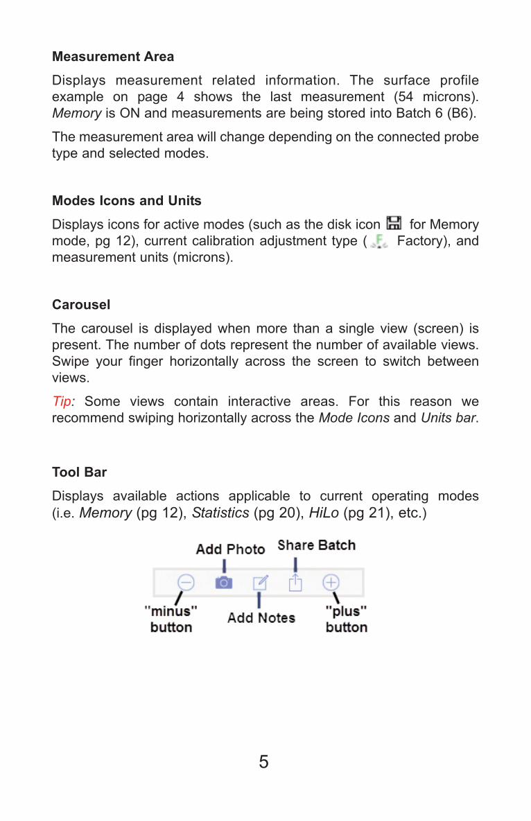
Measurement Area
Displays measurement related information. The surface profile
example on page 4 shows the last measurement (54 microns).
Memory is ON and measurements are being stored into Batch 6 (B6).
The measurement area will change depending on the connected probe
type and selected modes.
Modes Icons and Units
Displays icons for active modes (such as the disk icon X for Memory
mode, pg 12), current calibration adjustment type ( X Factory), and
measurement units (microns).
Carousel
The carousel is displayed when more than a single view (screen) is
present. The number of dots represent the number of available views.
Swipe your finger horizontally across the screen to switch between
views.
Tip: Some views contain interactive areas. For this reason we
recommend swiping horizontally across the Mode Icons and Units bar.
Tool Bar
Displays available actions applicable to current operating modes
(i.e. Memory (pg 12), Statistics (pg 20), HiLo (pg 21), etc.)

6
The PosiTector SmartLink acts as a relay between the PosiTector
probe and PosiTector App using wireless Bluetooth Smart
(BLE Bluetooth Low Energy). No pairing required! Auto-pairing
Bluetooth connection works up to 10 m (30 feet) away.
Information specific to currently selected modes and user
calibration adjustments (specific to each probe) are retained within
the PosiTector SmartLink. This allows for seamless switching
between smart devices (phone and tablet).
Measurement data is not stored within the PosiTector
SmartLink. All measurement data (readings, images, notes) is
stored within the PosiTector App on your smart device.
PosiTector PosiTector SmartLinkSmartLink
NOTE:
Connect a Probe
To connect a probe, slide the plastic probe connector in the direction
of the arrow (shown above) until it locks in place. Reverse for
detaching the probe.
When powered-up, the PosiTector SmartLink automatically determines
what type of probe is attached and does a self-check. The probe type,
model and serial number are displayed when found within the app's
Search screen.

7
The PosiTector App features probe hot-swap. During the
measurement process, probes can be interchanged without the need
to go back to the search screen. Simply swap probes (PosiTector
SmartLink will power-down) and then power-up the PosiTector
SmartLink. The PosiTector App will automatically recognize the probe
and be ready to measure.
NOTE:
Power-up / Power-down
The PosiTector SmartLink powers-up when the LED button is pressed.
To preserve battery life, the PosiTector SmartLink powers-down after
5 minutes of no activity. Alternatively, press and hold the LED button
until it turns red and shuts off (approximately 5 seconds). All probe
settings and calibration adjustments are retained, stored measurement
data is retained within the smart device.
Tri-Color LED Button
The LED visually provides connection and measurement status.
LED Color Status:
Blue Blink = Not Connected to PosiTector App
Blue Solid = Connected to PosiTector App
Green Blink = Successful Reading
8
PosiTector PosiTector SPGSPG ProbesProbesPosiTector SPG probes measure the peak-to-valley height of the
surface profile of abrasive blast cleaned surfaces.
The supplied probe tip has a 60° angle to comply with most test
standards including ASTM D 4417 B. An optional 30° angle tip with
replacement tool is available for special applications or to comply
with Australian Standard AS 3894.5.
A replacement tool is included with the purchase of either the 60°
or 30° angle tips. Insert the two legs of the replacement tool into
the probe tip and turn counter clockwise to remove the tip. Insert
the new tip and tighten clockwise. Do not over tighten. Since the
factory zero setting may not always be precise after a probe tip
exchange, the gage should be checked on the included glass plate
and zeroed if necessary.
More probe information is available at www.defelsko.com/spg
Protective Cap
PosiTector SPG probes are shipped with a protective rubber cap.
Remove this cap prior to use. Replace it when the instrument is not in
use to protect the probe.
Factory Calibration
Every PosiTector SPG probe is factory calibrated and includes a
Certificate of Calibration. This factory calibration information is
permanently stored within the probe and cannot be overwritten by the
user. The XX icon indicates factory calibration is in use.
Calibration Adjustment
The PosiTector SPG has only one adjustment point at zero. The Zero
adjustment made by the user is stored within the PosiTector
SmartLink.
9
Certification
PosiTector SPG probes include a Certificate of Calibration showing
traceability to a National Metrology Institution. For organizations with
re-certification requirements, instruments may be returned at regular
intervals for calibration. DeFelsko recommends that customers
establish calibration intervals based upon their own experience and
work environment. Based on our product knowledge, data and
customer feedback; a one year calibration interval from either the date
of calibration, date of purchase, or date of receipt is a typical starting
point.
Calibration, Verification & AdjustmentCalibration, Verification & Adjustment
The PosiTector SPG probes measure the peak-to-valley height of the
surface profile of abrasive blast cleaned surfaces.
Three steps ensure best accuracy...
1. Calibration - typically done by the manufacturer. All probes include a
Certificate of Calibration
2. Verification - typically done by the user on known reference
standards such as included metal shim
3. Adjustment - zero calibration adjustment on smooth flat surface
(included glass plate)
Calibration
Calibration is the high-level, controlled and documented process of
measuring traceable calibration standards over the full operating range
of the probe, and verifying that the results are within the stated
accuracy of the probe. Calibrations are performed by the manufacturer,
their authorized agent, or by an accredited calibration laboratory in a
controlled environment using a documented process.
PosiTector SPG probes are shipped with a Certificate of Calibration
showing traceability to a National Metrology Institution. For
organizations with re-certification requirements, probes may be
returned at regular intervals for calibration. DeFelsko recommends that
customers establish calibration intervals based upon their own
experience and work environment. Based on DeFelsko’s product
knowledge, data and customer feedback, a one year calibration interval
from either the last date of calibration, date of purchase, or date of
receipt is a typical starting point.
Written Calibration Procedures are available online at no charge.
http://www.defelsko.com/quality/calibration_procedures.htm

10
Verification
Verification is an accuracy check performed by the user using known
reference standards. A successful verification requires the Gage to
read within the combined accuracy of the probe and the reference
standards.
Instrument accuracy is verified using the included metal shim and glass
zero plate.
Place the plate onto a stable, flat surface. Take several readings. If the
average is not with tolerance of the probe, zero the probe.
Next, place the metal shim over the glass plate and measure ensuring
the probe needle touches the glass plate in the area between the
shim’s “legs”. The average of several readings should be within the
combined tolerances of both the shim and the gage.
Verify accuracy at the beginning and the end of each work shift. During
the work shift, if the Gage is dropped or suspected of giving erroneous
readings, its accuracy should be re-verified. In the event of physical
damage, wear, high usage, or after an established calibration interval;
the probe should be returned to the manufacturer for repair or
calibration.
Zero Calibration Adjustment
The PosiTector SPG has only one adjustment point at zero.
Zeroing the probe on the glass plate is the preferred zero adjustment
method:
Select Zero from the menu.1
Press the X button to select the number of readings to be used2
to obtain an average, typically 3.
Repeatedly measure the glass plate. After the last reading the3
gage will calculate a Zero which represents the average of all the
Zero readings taken.
The X icon will display.
If a glass plate or suitable smooth, hard surface is not
available, factory zero calibration can be used. Factory calibration can
be restored by performing a Reset (LED Button Reset, pg 23).
The factory zero setting may not always be precise, particularly after a
probe tip exchange. For best accuracy, the gage should be zeroed
on the included glass plate.
NOTE:

11
Menu OperationMenu Operation
PosiTector SPG functions are menu controlled. Access them by
selecting Menu in the upper right of the PosiTector App display.
The Main Menu contains the following sub-menus...
Memory (pg 12)•Statistics (pg 20)•Zero (pg 10)•Setup (pg 22)•
Select Exit to close the menu.
12
Memory MenuMemory Menu
The PosiTector App uses your smart device's storage for recording
measurement data. Stored measurements can be reviewed
on-screen or shared via email (PDF, CSV). Measurements are date
and time-stamped (using date/time from smart device).
The following options appear within the Memory menu.
Additional options may appear depending on the connected
PosiTector SmartLink and probe type.
New Batch
Closes any currently opened batch and creates a new batch name
using the lowest available number. For example, if only Batch 1 and
Batch 3 exist, then Batch 2 would be created and made the current
batch.
The X icon appears and basic statistics are displayed. Each
measurement will be displayed and stored into this new batch. On
screen statistics are immediately updated with each measurement.
New batch names are date-stamped at the time they are created.
When a batch is open, press the LED button on the
PosiTector SmartLink or X icon on the display to create a new batch.
Shortcut:
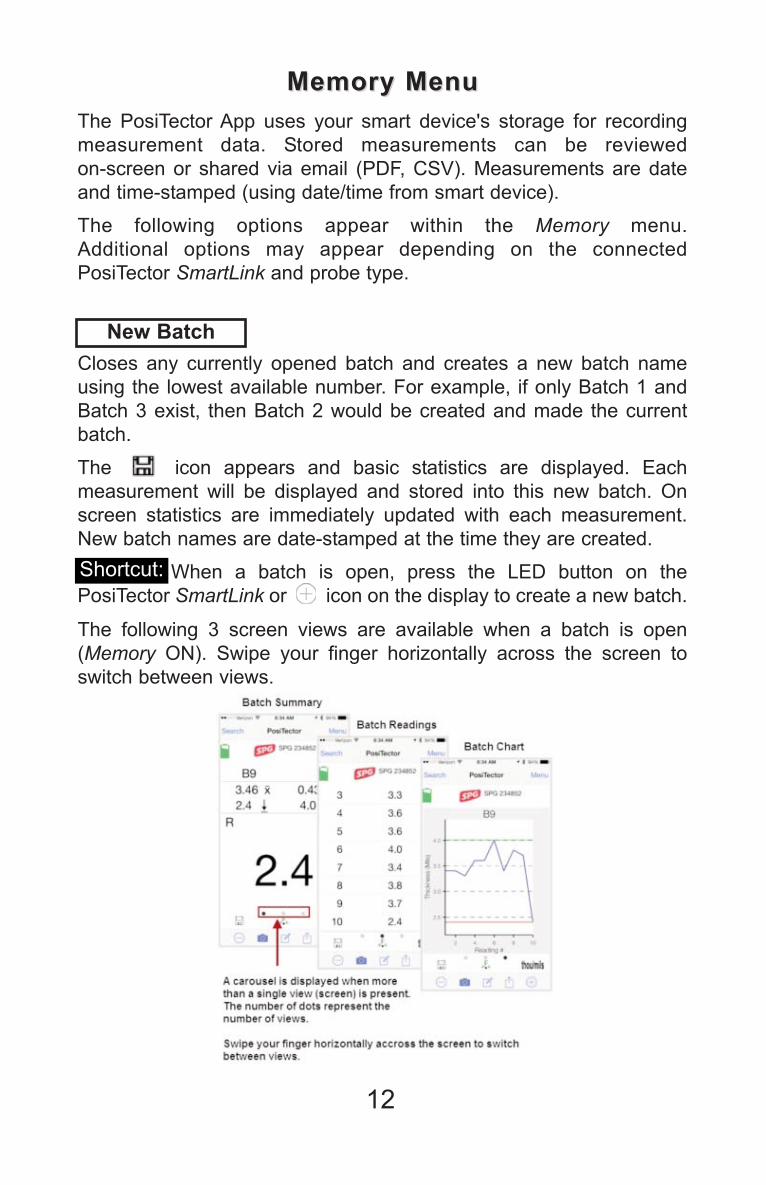
The following 3 screen views are available when a batch is open
(Memory ON). Swipe your finger horizontally across the screen to
switch between views.
13
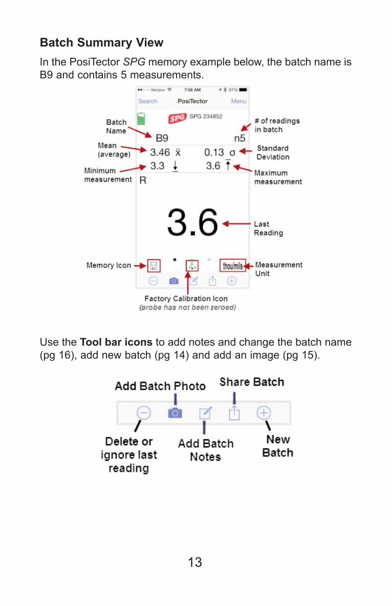
Use the Tool bar icons to add notes and change the batch name
(pg 16), add new batch (pg 14) and add an image (pg 15).
Batch Summary View
In the PosiTector SPG memory example below, the batch name is
B9 and contains 5 measurements.

14
Delete or Ignore last reading
from the current open batch.
When selected, the following menu
appears.
Ignore Readings are retained within
the batch but are excluded from the
report's statistical summaries and
charts.
The ignored readings are highlighted
within the Batch Readings View (Shown here. See also pg 17).
By default Ignored Readings are not
included on reports. For inclusion,
toggle the Hide Ignored Readings
within the Batch Report Configuration(pg 19. Ignored Readings will display
has highlighted within the readings
section of the report, but are excluded
from the statistical summary and chart.
Delete Reading permanently
removes the selected measurement
from the current batch.
Cancel exits the menu.
X New Batch
Closes any open batch and creates a new batch name using the
lowest available number.

15
Connection to a PosiTector SmartLink is not required to
add a photo or image annotation to an existing batch.
NOTE:
Add Image Annotation
Add Photo to the currently opened batch or dataset.
Batch Photo, Reading
Photos and Image
Annotations can be included
in reports.
The photo can be resized or
hidden from reports within
the Memory >> Batch Report
Configuration menu (pg 19).
This drawing tool is ideal for identifying a
specific location or area within an image.
Choose from three paint brush colors -
Red, Green or Blue.
Use finger or stylus to draw over the
displayed image.

16
Share Batch
Share/view professional PDF reports
and CSV data instantly via email,
Dropbox or other applications on the
smart device.
Report
Generate PDF reports instantly and share via email, Dropbox or other
applications on your smart device.
Batch reports can be customized within the Batch ReportConfiguration menu (pg 19).
Add Notes to currently opened
batch or dataset.
Change the batch name and add
batch notes using your smart device's
keyboard or dictation tools.
Batch names/notes appear on
reports.
Export
Email CSV (comma-delimited) comma-separated text files which can
easily be imported into supporting applications such as spreadsheets
and databases. A .json formatted file is also included.

17
Batch Readings View
Lists all readings contained in
the current batch.
New readings are added to the
list instantly as they are taken.
A note and/or photo can be
added to each individual
reading.
Notes and photos can be
displayed in batch reports.
Batch Chart View
Lists all readings contained in the
current batch. New readings are
added to the list instantly as they
are taken.
Pinch the active region of the
chart to zoom the view.

18
Open
Lists all stored batches. Select the desired batch to open.
Additional measurements can be added to existing batches only if
the original probe is attached to the PosiTector SmartLink.
Opening a batch that was not created with the currently
attached probe will disconnect the PosiTector SmartLink from the
PosiTector App. You will still be able to add notes, photos, etc. to
the batch.
NOTE:
Close
Closes the current batch and turns Memory OFF.
Batch measurement data is retained when a batch is closed.
19
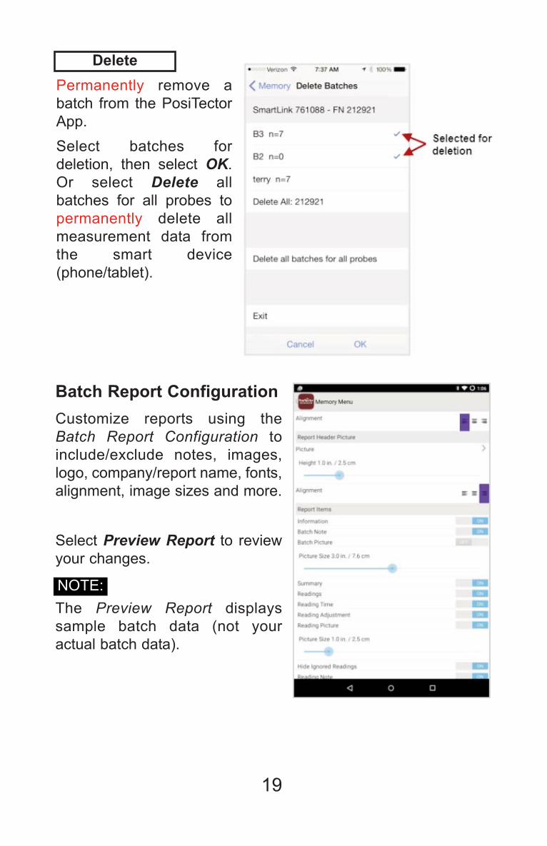
Delete
Permanently remove a
batch from the PosiTector
App.
Select batches for
deletion, then select OK.
Or select Delete all
batches for all probes to
permanently delete all
measurement data from
the smart device
(phone/tablet).
Batch Report Configuration
Customize reports using the
Batch Report Configuration to
include/exclude notes, images,
logo, company/report name, fonts,
alignment, image sizes and more.
Select Preview Report to review
your changes.
The Preview Report displays
sample batch data (not your
actual batch data).
NOTE:

20
When toggled ON, the icon appears and a statistical summary
is displayed.
Statistics MenuStatistics Menu
Statistics
x
Deletes the last reading. Press Clear or the LED button on the
PosiTector SmartLink to clear statistics.
Batch Report
Generate a report summarizing an
individual batch or multiple
batches.
Select desired batch or batches to
include in the report and press OK.
Share the report instantly via
email, Dropbox or other
applications on your device.

21
HiLo Alarm
When toggled ON, user is visibly alerted when measurements
exceed user-specified limits defined in HiLo Alarm Limits.
The X icon will appear on the display.
HiLo Alarm Limits
Define Lo and Hi alarm limits by
selecting (touching) the appropriate
box.
When selected a number pad appears.
Enter the desired Lo and Hi Limit
value.
Select Done to accept the value.
When HiLo Alarm is toggled ON,
measurements will be compared to
your defined HiLo limits.
Press Clear to clear HiLo tabulations.
Clear
Clears all on-screen HiLo tabulations.

22
The PosiTector SmartLink is not visible on other smart
devices while you are connected (once you have selected the
PosiTector SmartLink from the Search screen).
NOTE:
Setup MenuSetup Menu
SmartLink Info
Provides information about the
currently connected PosiTector
SmartLink, Probe and
PosiTector App version.
Change Units
Converts the display from imperial to metric or vice versa. Stored
readings in memory are not converted.
Switching units will turn off Statistics (pg 20), HiLo Alarm (pg 21),
and close Memory (pg 12).
SmartLink Lock
Locks the PosiTector SmartLinkto a smart device. This prevents
other PosiTector App users
within range (10 m / 30 ft) from
inadvertently connecting to a
SmartLink.
Toggle the SmartLink Lock X
within the Setup menu to lock the
PosiTector SmartLink to a smart
device. You will have to unlock it
if you want to wirelessly connect
to another smart device.

23
Reset
Restores factory default settings. Ideal for returning settings to a
known condition.
There are two available Reset options:
Menu Reset and PosiTector SmartLink (LED Button) Reset
Menu Reset (PosiTector App)
Select Reset from the Setup Menu.
The following occurs after a warning
message:
All stored batches, measurements,•
images, notes, annotations are
deleted.
All calibration settings (adjustments)•
and Cal Memory are cleared and
restored back to factory settings
(provided PosiTector SmartLink is
ON and connected to App).
To keep calibration settings, power
off the PosiTector SmartLink prior to
performing this Menu Reset.
Settings are returned to
the following:
Memory = OFF
Statistics = OFF
Units = Microns
HiLo Limits = OFF
Report ConfigurationSettings = restored to
default
With the PosiTector SmartLinkpowered-down, press and hold the LED
button until it flashes green
(approximately 10 seconds).
The following occurs...
All calibration settings (adjustments)•
are cleared and restored back to
factory settings.
Settings are returned to
the following:
Units = Microns
SmartLink Lock = OFF
LED Button Reset (PosiTector SmartLink)
24
Profile depth readings are inconsistent
The complex nature of a blasted steel surface will result in reading
variations. If readings are inconsistent on a smooth surface, the probe
tip may be damaged, scratched or worn.
PosiTector SmartLink not displaying on search screen
Ensure PosiTector SmartLink is powered-up (pg 7), LED is blinking
blue and is within range.
Refresh the search using the arrow icon in the upper left of the display.
Verify Bluetooth is ON in smart device settings.
Camera does not function when attempting to add photo
Verify adequate privacy permissions are set for the PosiTector App.
TroubleshootingTroubleshooting
Limited Warranty, Sole RemedyLimited Warranty, Sole Remedy
and Limited Liabilityand Limited Liability
DeFelsko's sole warranty, remedy, and liability are the express
limited warranty, remedy, and limited liability that are set forth on
its website: www.defelsko.com/terms

25
Simple. Durable. Accurate.
www.defelsko.com
© DeFelsko Corporation USA 2015
All Rights Reserved
This manual is copyrighted with all rights reserved and may not be
reproduced or transmitted, in whole or part, by any means, without written
permission from DeFelsko Corporation.
DeFelsko and PosiTector are trademarks of DeFelsko Corporation registered
in the U.S. and in other countries. Other brand or product names are
trademarks or registered trademarks of their respective holders.
Every effort has been made to ensure that the information in this manual is
accurate. DeFelsko is not responsible for printing or clerical errors.
This device complies with part 15 of the FCC Rules. Operation is subject to
the following two conditions: (1) This device may not cause harmful
interference, and (2) this device must accept any interference received,
including interference that may cause undesired operation.


