Assessing the Significance of Flaws in Welds Subject to Fatigue Use of fracture mechanics analysis for fatigue is consid ered and examples are given of applications to some practical types of weld joints and flaws BYS.J.MADDOX Summary. It is now widely recognized that flaws will inevitably exist in welded structures and the old idea of removing all detectable defects must be replaced by the 'fitness for purpose' design philosophy. This makes it necessary to define reliable methods of assessing the significance of flaws, particularly in the context of fatigue, a fracture mechanism critically affected by flaws. The most prom ising ap proach to this problem lies in the use of the fracture mechanics based description of fatigue crack propaga tion. This paper is concerned with the practical application of fracture mechanics to the problem of fatigue of welded joints containing cracks or defects. Introduction The attitude of fabricators and de signers to flaws in welded structures has changed over the past few years. The automatic reaction in the past of repairing all regions found to contain flaws is being replaced by the 'fitness for purpose' design philosophy, whereby flaws which would not bring about premature failure may be ig nored. There are several reasons for 5. J. MADDOX is associated with The Welding Institute, Abington Hall, Abington, Cambridge, England. Paper was presented at the 55th A WS Annual Meeting held at Houston during May 6-10, 1974. this change in attitude but the prin cipal ones are widespread recognition of the facts that all welds contain flaws and that the chances of detect ing them depend on the sensitivity of the nondestructive inspection method; that repair is expensive and may be unnecessary; that repair may introduce more harmful flaws, such as cracks arising from repair welds made under difficult conditions. This paper is concerned with flaw assessment in the context of fatigue, a fracture mechanism critically affected by the presence of flaws. The prob lems of presenting information about the fatigue behavior of flaws of vary ing sizes in the form of simple data is discussed. The main part of the paper deals with the application of fracture mechanics to this problem, with par ticular reference to both surface and buried planarflaws. From the general point of view, the principles discussed should be appli cable to any material. However, data presented all refer to structural C-Mn steels. Problem of Flaw Assessment The fatigue properties of many welded joints can be represented on the conventional S-N diagram where, for a given material and joint type, applied stress is plotted against endur ance. Data presented in this way and analyzed statistically have been used to provide design S-N curves (Ref. 1). The value of the S-N diagram for es timating fatigue life depends on the fact that, in many cases, all relevant variables apart from applied stress, such as material and geometric stress concentration, remain approximately constant. Variations in these 'con stants' contribute to scatter in S-N data and reduce the confidence with which lives can be predicted. In most welded joints, certainly the lower strength joints which fail from the weld toe or root, fatigue failure ini tiates at flaws (Refs. 2,3). In many cases, the severity of the relevant flaw does not vary enough from joint to joint to limit the value of the S-N diagram. However, the severity of some flaws can vary considerably. In such cases, data represented on an S- N diagram wou ld be of value only if the severity of the flaw could be expressed simply or specified. For example, if both the joint type and size of flaw were specified. This approach has proved to be possible in the cases of butt welds with uniform porosity (Ref. 4 ), where severity can be character ized simply in terms of its volume, and slag inclusions in arc welded joints, where the severity of the flaw de pends on both its depth and length but may be characterized by the length since the depth does not vary much (Ref. 5). Thus, comparisons between the expected fatigue life of the flaw, the fatigue lives of other welded de tails present and the required service life can be made easily. Flaw accep- WELDING RESEARCH SUPPLEMENT 401-s
As sess ing the Significance of Flaw sin W e lds S ubject to Fat igue
Use of fracture mechanics analysis for fatigue is considered and examples are given of applications to som epractical types of weld joints and flaws
BYS .J .MADDOX
Summary . I t i s now w ide l y recogn izedthat f laws wi l l inev i tab ly ex is t inwelded s t ructures and the o ld idea ofremo v ing a l l de tec tab le de fec ts mus tbe rep laced by the 'f i tness f o r pu rpose 'des ign ph i losophy. Th is makes i t
necessa ry to de f i ne re l i ab le me thodso f assess ing the s ign i f i cance o f f l aws ,par t icu lar ly in the context o f fa t igue, af rac tu re mechan ism c r i t i ca l l y a f fec tedby f l aws . The mos t p rom is ing a p proach to th is prob lem l ies in the useo f the f rac tu re me chan ics baseddesc r ip t i on o f f a t i gue c rack p ropaga
t i o n . Th i s paper is conc erned w i th thep rac t i ca l app l i ca t i on o f f rac tu remec han ics to the p rob lem o f fa t i gue o f
we ld ed j o in t s con ta in in g c racks o rdefects .
I n t r o d u c t i o n
The a t t i t ude o f f ab r i ca to rs and de s igne rs to f l aw s i n we lded s t ruc tu reshas changed ove r the pas t f ew years .The automat ic react ion in the past o frepa i r i ng a l l reg ions found to con ta inflaws is be in g rep laced by the ' f i tne ssf o r p u r p o s e ' d e s i g n p h i l o s o p h y ,w h e r e b y f l a w s w h i c h w o u l d n o t b r i n gabou t p rematu re fa i l u re may be i g n o re d . The re a re seve ra l reasons fo r
5. J. MADDOX is associated with TheWelding Institute, Abington Hall, Abington,Cambridge, England.
Paper was presented at the 55th A WSAnnual M eeting held at Houston duringMay 6-10, 1974.
th is change in a t t i tude but the p r i n
c ipa l ones a re w idespre ad recogn i t i onof the facts that a l l welds conta inf l aws and tha t t he chances o f de tec t i ng them depend on the sens i t i v i t y o ft h e n o n d e s t r u c t i v e i n s p e c t i o n
m e t h o d ; tha t repai r is expe nsive andmay be unne cessa ry; tha t repai r m ayin t roduce more ha rmfu l f l aws , such asc racks a r i s i ng f rom repa i r we ld s madeunder d i f fi cu l t co nd i t i ons .
Th is paper i s concerned w i th f l awassessment in the context o f fa t igue, af rac tu re mechan ism c r i t i ca l l y a f fec tedby the p resence o f f l aws . The p rob lems o f p resen t ing i n fo rm a t ion abou tthe fa t igue behavior o f f laws of varying s izes in the form of s imp le data is
d i s c u s s e d . The ma in par t o f the p aperdea ls w i th the a pp l i ca t i on o f f rac tu re
m e c h a n i c s t o t h i s p r o b l e m , w i t h p a r
t icu lar re fe renc e to both sur face andb u r i e d p l a n a r f l a w s .
F rom the genera l po in t o f v iew , thep r inc ip les d i scussed shou ld be app l i cab le to any ma te r ia l . However , da tap resen ted a l l r e fe r t o s t ruc tu ra l C -Mnsteels .
P r o b l e m o f F l a w A s s e s s m e n t
The fa t i gue p roper t i es o f m anywe lded j o in t s can be rep resen ted ont h e c o n v e n t i o n a l S - N d i a g r a m w h e r e ,fo r a g i ven ma te r ia l and j o in t t ype ,appl ied s t ress is p lo t ted aga inst end ura n c e . Da ta p resen ted i n th i s way andanaly zed s ta t is t ica l ly have been usedto prov ide des ign S-N curves (Ref . 1) .
The va lue of the S-N d ia gra m for es t ima t ing fa t i gue l i f e depends on thefact that , in many cases, a l l re levantva r iab les apar t f rom app l i ed s t ress ,such as ma te r ia l and geomet r i c s t ressc o n c e n t r a t i o n , r e m a i n a p p r o x i m a t e l y
cons tan t . Va r ia t i ons i n these ' c o n sta nts ' con t r ibu te to scat te r in S-Nda ta and reduce the con f i de nce w i thwh ich l ives can be p red i c ted .
In mos t we lded j o in t s , ce r ta in l y thelower s t reng th j o in t s wh ich fa i l f r omthe weld toe or root , fa t igue fa i lure i n i t ia tes at f laws (Refs . 2 ,3) . In manycases, the sever i ty o f the re lev ant f la wdoes no t va ry enough f rom jo in t t ojo in t to l imi t the va lue of the S-Nd i a g r a m . However , t he seve r i t y o fsome f l aws can va ry cons ide rab ly . I nsuch cases, data represented on an S-N d iag ra m wou ld be o f value on ly i f thesever i ty o f the f law could be expressedsimply or spec i f ied. For example, i fboth the jo in t type and s ize of f lawwe re spec i f i ed . Th i s app roach hasproved to be poss ib le in the cases ofbu t t we lds w i th un i fo rm po ros i t y (Re f .4 ), wh ere sev e r i t y can be ch a rac te r ized s im ply in term s of its vo lum e, a nds lag i nc lus ions i n a rc we lded j o in t s ,where the seve r i t y o f t he f l aw de pend s on bo th i ts dep th and length butmay be char acter iz ed by the leng ths ince the depth does not vary much(Ref . 5 ). Thus , com par i son s be tw eenthe expected fa t igue l i fe o f the f law,the fa t i gue l i ves o f o the r we lded de
ta i ls prese nt and the requ i red serv icel i f e can be made eas i l y . F law accep-
W E L D I N G R E S E A R C H S U P P L E M E N T 4 0 1 - s
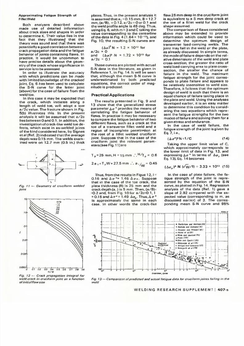
w e l d . In cont rast , so lu t ions for K inthe l i t e ra tu re a re con f i ne d mos t l y toregu la r shaped c rack s i t ua t i ons i ns imp le s t ress f i e lds . An add i t i o na lcom p l i ca t i o n i s tha t f l aw s as soc ia tedw i th we lds a re pa r t embedde d (su r
face ) o r f u l l y em bedd ed (bu r ied ) an dfew so lu t i ons fo r such c racks a reavai lab le . The t r iax ia l c rack t ip s t ressf i e l d a s s o c i a te d w i t h e m b e d d e dc racks i nc reases the d i f f i cu l t i es o f
de t e rm in ing K . Re levan t so lu t i ons a rein t roduced in the ana lyses wh ichfo l l ow .
Fatigue Fai lure from Toe of Fi l let
Weld
Fa t igue c racks w h ic h p ro paga tef rom the toe o f a w e l d , and i ndeedf rom mos t su r face s t ress concen t ra t i o n s , adop t a sem i -e l l i p t i ca l p ro f i l e .Some examp les o f ac tua l c racks a resh ow n in F ig . 5 , wh i l e F ig . 6 show s asketch of a crack. In Re fe rence 25 a
so lu t i on fo r t he s t ress i n tens i t y fac to ro f a sem i -e l l i p t i ca l su r face c rack s i t
ua ted a t t he toe o f a we ld was de te r m i n e d . The co r rec t i on te rm Y (see Eq .2 ) depe nds on th e c rack shape a / 2c ,the c rack dep th a / B an d the s t ressc o n c e n t r a t i o n e f fe c t of the w e l d g e o m e t ry . The gene ra l so lu t i on m ay bew r i t t e n
Iv 5 CTVTT d
o
where
(10)
Fig. 6 — Semi-elliptic surface crack in a
plate in tens/on
Ms i s t he co r rec t i on fo r c rack f ron t
s h a p e a n d d e p e n d s o n a / 2 c<S>o i s t he com p le te e l l i p t i c i n teg ra l
(ob ta ined f rom s tand ard tab les )and a l so depends on a /2 c
M t is the cor rec t ion facto r for crack
f ron t pos i t i on and depends ona /B a n d a /2 c
Mk i s t he co r re c t i on to take accoun to f we ld profile s tr e s s c o n c e n t r a t i on
I t w i l l be no ted tha t no co r r ec t i on i smade for crack t ip p last ic i ty . In fa t iguei t is rare that such a correct ion is requ i red s ince the cyc l ic crack t ip p last ic zone is sm al l , due to reve rsedy ie ld ing (Ref . 26) .
F igu re 7 sh ow s the cu rves re la t i ng
M s M , / „ and a / B . Curves re la t i ngM k and a / B as ca l cu la ted fo r 30 and45 deg f i l l e t we lds and es t ima ted fo r
60 deg welds, (Ref . 25) are g iven inFig . 8 .
From Figure 7 i t w i l l be noted that i fa /2c i s g rea te r than 0 .2 , Ms M , / „
cou ld be regarded as a cons tan t . Ho wever , in pract ice sur face fa t igue
c r a c k s a s s o c i a t e d w i t h w e l d e d j o i n t sadop t a /2c va lues wh ich , a t l eas t i nthe impor tan t ea r l y s tages o f c rackp ropa ga t ion , a re l ower than 0 .2(Ref. 24).
The above so lu t i on fo r K was usedin con ju nc t i on w i th the c rack p ro p a g a t i o n law w i t h m = 3 t o c o r r e l a t e f a
t i gue da ta ob ta in ed f rom we lded
j o i n t s w h i c h c o n t a i n e d c r a c k s o fkn ow n s i zes . The spec imen s w erep la tes w i th l ong i tud in a l s t i f f en e rsw h i c h w e r e f il l e t w e l d e d a r o u n d t h e i rends ( jo in t (d) in F ig . 5) loaded wi th
R = 0 . F a i l u r e , d e f i n e d a s t h r o u g h -th i ckne ss c rack ing , occu r red a f te rc rack p ropaga t ion f rom the toe o f t hewe ld a t t he end o f t he s t i f f ene r . The
s p e c i m e n s w e r e p r e c r a c k e d a n d t h ef rac tu re su r face marked w i th soaps o l u t i o n . S ta ins p roduced in th i s w ayare shown on f racture sur faces (b) to(d) in F ig . 5 . Crack dept hs be tw ee n0 .1 and 4 .8 mm in spec im ens 12 .7mm (0 .5 i n .) t h i ck w ere p roduce d .
Ag- *wa s ca l cu la ted fo r each spec i m e n , t ak ing i n to cons ide ra t i on thew e l d a n g l e , w h i c h w a s m e a s u r e d ,and the expec ted c rack shape v a r ia t i on based on a c lose s tudy o f f a i l u rein th i s spec ime n type (Ref . 9 ,24) . Theresul ts are g iven in F ig . 9 , togetherw i th p red i c ted sca t te r l im i t s based onthe crack pro pa gat ion data in F ig . 4 . I tw i l l be see n tha t a l l t he da ta fe l l
w i th in the p red i c ted l im i t s . Thus , i n d i v idua l t es t resu l t s cou ld have beenpredic ted us ing Eq. 6 , to an accuracyco r re spon d ing to the sca t te r l im i t s ,and tes t da ta ob ta ined f rom un l i kespec imens ( i n i t i a l c rack s i ze , c rackshape and we ld p ro f i l e va ry ing ) a resuccess fu l l y co r re la ted us ing ACT*.
Since K was no t based on a c losed-fo rm so lu t i on , t he i n teg ra t i on i n th e
above ana lys i s was ca r r i ed ou t g raphi ca ll y . The resu l t i ng ca l cu la t i ons we res imp l i f i ed w i th the a id o f a d iag ramre la t i ng the i n teg ra l , I, w i th th e i n i t i a lcrack d e p t h (a/B) f o r ( a / B ) f = 1 . S u c ha d iag ram , w h i ch i n c ludes cu rves fo rcons tan t va lues o f a / 2c , 0 and 0 .1 ,and 45 deg f i l l e t we lds , i s shown onlogar i thmic sca les in F ig . 10. If a di f
f e ren t f a i l u re c r i t e r i on i s app l i cab le ,
fo r examp le fa i l u re a t a /B l ess than 1 ,t he same d iag ram cou ld be used ,s ince fo r ( a / B ) ; =x , I f o r ( a / B ) f =y isequal to I f o r (a /B ) , =x m in us I for( a / B ) f =y . It w i l l be noted that as long
Fig. 7 — Stress intensity correction termMsMt/<£>0 for surface crack as a function
of crack depthFig. 8 — Stress intensity magnification due to stress concentration, Mk. Solid line from finite
element analysis (Ref. 9), broken line estimated (Ref. 25)
W E L D I N G R E S E A R C H S U P P L E M E N T 4 0 5 -s
Concisely presentedr « i i i 7 n r l w I information of great value
to everyone in the industryE T A L L U R G Y
WELDING METALLURGY, by G eo rge E . L in ne rt , offers a c on cis e b ut com
prehensive t rea tm ent o f the g reat mas s of techn ica l in format ion nowavailable in this f ield . The subject matter is divided into two volumes.Volume I — Fu nd am en ta ls — is des igned to p rov ide the bas ic in for
ma t io n n ecessa ry fo r an y r ea l u n d er s t an d in g o f we ld in g a s a ma jo r to o lof the s tee l fabr ic a t ing ind ust r y . I t beg ins wi th the esse n t ia ls o f weld in gand meta l lu rgy , considered separa te ly . I t concludes wi th a s tudy showinghow the weld ing thermal cycle a l ters the micros t ructu re o f the jo in t andhow th is a l tera t ion , in tu rn , af fec ts jo in t p roper t ies .
In Volum e I I — T echno logy — the ea r l ier ma ter ia l i s developed i ngreate r deta i l , focus ing on the specif ic fac to rs an d cond i t ions th at requ ireco n s id e ra t io n wh en d ea l in g w i th p a r t i cu la r p ro jec t s . Th e d i scu ss io n s ,i l lus t ra t ions , and da ta tab le s in V olume 2 ag ai n fo llow th e bas ic meta l lu r g ica l approach to each sub ject area . In th is manner , a s t rong unders tand ing of the bas ics i s p rov ided , which the reader may eas i ly re in force
by specia l ized s tudy in to whatever o ther aspects are deemed impor tan t .These two vo lumes wi l l p rove usefu l no t on ly in o r ien t ing the nov icewelding engineer to this broad field of welding, but also in helping themore exper ienced profess ional who needs ass is tance in f ind ing a ra t ionalbas is fo r so lv ing p rob lems.
Volume I , Fun dam ent a ls $13.00
V olume II , T ech nolo gy $15.00
Discoun ts : 25% to A and B me mb ers ; 20% to booksto res , pub l icl ib rar ies and schools ; 15% to C and D members .
Send your order to the American Welding Society, 2501 NW 7th St. ,Miam i , FL 33125. F lo r ida r es ide n ts add 4% sales tax .
IA n introduction to the subject
that even experienced
inspec tors will refer to often
WELDING INSPECTION des cribe s the ge ne ra l dutie s an d res pon sibi litie sof inspec to rs of weldm ents . Because the d iscuss ions a re more genera lthan those found in part icular codes and specifications, i t is especiallyuseful for training inspectors.
Among the top ics covered are : requ irements fo r an inspector ; du t iesof an inspec tor; we lding proced ure specification; qu alific ation of we ldingprocedures ; qual i f ica t ion o f welders and weld ing opera to rs ; weldmentdefects, and d es t ruct ive and non des t ruct iv e te s t ing o f welds . $10 .00.
Disco unts: 25% to A an d B mem bers ; 20% to bookstores, publicl ib rar ies an d schools; 15% to C and D mem b ers .
Send your order to the American Welding Society, 2501 NW 7th St. ,Miam i , FL 33125 . F lo r ida re s iden ts add 4% sa les tax .