LED Indicators PWR, FAULT, STATE, WLAN1, WLAN2, LAN1, LAN2 PWR, FAULT, STATE, WLAN, LAN PWR1, PWR2, PoE, FAULT, STATE,
WLAN1, WLAN2, 10M, 100MPWR1, PWR2, PoE, FAULT, STATE, signal strength, CLIENT MODE, BRIDGE MODE, WLAN, 10M, 100M
Alarm Contact (Digital Output) 1 1 1 1
Digital Inputs 2 2 2 2DI/DO Connector Type 8-pin M12 (A-coding) 10-pin terminal blockPhysical Characteristics
Housing Metal (IP67) Metal (IP67) Metal (IP30) Metal (IP30)Weight 1.22 kg 1.2 kg 880 g 850 gDimensions 224 x 147.7 x 66.5 mm 62.05 x 135 x 105 mm 53.6 x 135 x 105 mm
InstallationWall mounting (standard), DIN-Rail mounting (optional), pole mounting (optional)
Wall mounting (standard), DIN-Rail mounting (optional), pole mounting (optional)
Environmental LimitsOperating Temperature -40 to 75°C -40 to 75°C 0 to 60°C or -40 to 75°C 0 to 60°C or -40 to 75°COperating Humidity 5% to 95% 5% to 95% 5% to 95% 5% to 95%Storage Temperature -40 to 85°C -40 to 85°C -40 to 85°C -40 to 85°CPower Requirements
Input Voltage Redundant dual power inputs (12 to 48 VDC)Connector 5-pin M12 (A-coding) 10-pin terminal blockIEEE 802.3af 48 VDC PoE √ √ √ √
Max. Transmission Rate 54 Mbps 54 Mbps 54 MbpsMax. Transmission Distance 300 m 100 m 100 m
LAN InterfaceEthernet Ports 1 x 10/100 Mbps (RJ45) 1 x 10/100 Mbps (RJ45) 1 x 10/100 Mbps (RJ45)1.5 KV Magnetic Isolation Protection √ √ √
Serial InterfaceNumber of Ports 4 1 2Serial Standards RS-232/422/485 RS-232/422/485 RS-232/422/485Connector RJ45 DB9-M DB9-MConsole Port √ --- ---Serial Communication Parameters
Data Bits: 5, 6, 7, 8; Stop Bits: 1, 1.5, 2; Parity: None, Even, Odd, Space, Mark
Data Bits: 5, 6, 7, 8; Stop Bits: 1, 1.5, 2; Parity: None, Even, Odd, Space, Mark
Data Bits: 5, 6, 7, 8; Stop Bits: 1, 1.5, 2; Parity: None, Even, Odd, Space, Mark
Flow Control RTS/CTS, XON/XOFF, DTR/DSR RTS/CTS, XON/XOFF RTS/CTS, XON/XOFFBaudrate 50 bps to 460.8 Kbps 50 bps to 921.6 Kbps 50 bps to 921.6 KbpsSerial Data Log 64 KB 64 KB 64 KB
Utilities NPort® Search Utility and NPort® Windows Driver managerWindows Real COM Drivers Windows 95, 98, ME, NT, 2000, XP x86/x64, 2003 x86/x64, Vista x86/x64, 2008 x86/x64, Embedded CE 5.0/6.0, XP Embedded
Fixed TTY Drivers SCO Unix, SCO OpenServer, UnixWare 7, UnixWare 2.1, SVR 4.2, QNX 4.25, QNX 6, Solaris 10, FreeBSD, AIX 5.x, HP-UX 11iLinux Real TTY Drivers Linux 2.4.x/2.6.x
Physical CharacteristicsHousing Metal (IP30) AluminumWeight 1730 g 780 gDimensions 45.8 x 135 x 105 mm 77 x 111 x 26 mm
Environmental LimitsOperating Temperature 0 to 60°C 0 to 55°C or -40 to 75°COperating Humidity 5% to 95% 5% to 95%Storage Temperature -20 to 85°C -40 to 85°C
Power RequirementsInput Voltage 12 to 48 VDC 12 to 48 VDCPower Consumption 685 mA @ 12 V, 340 mA @ 24 V, 185 mA @ 48 V 560 mA @ 12 V, 294 mA @ 24 V, 162 mA @ 48 V
Regulatory ApprovalsSafety UL (UL60950-1), TÜV (EN60950-1) UL (UL60950-1), TUV (EN60950-1)Radio CE (ETSI EN 300 328) CE (ETSI EN 301 893, ETSI EN 300 328), ARIB RCR STD-33, ARIB STD-66
EMC CE (EN55022 and EN55024 Class A, ETSI EN 301 489-17, ETSI EN 301 489-1) CE (EN55022 and EN55024 Class A, ETSI EN 301 489-17, ETSI EN 301 489-1)
EMI FCC (Part 15 Subpart B Class A, Subpart C) FCC Part 15 (Subpart B Class A, Subpart C, Subpart E), VCCI
ReliabilityMTBF 81,501 hrs 352,547 hrs 352,034 hrsWarranty 5 years (see www.moxa.com/warranty)
13-4 w w w. m o x a . c o m i n f o @ m o x a . c o m
Cellular InterfaceStandards UMTS/HSDPA GSM/GPRS UMTS/HSDPA GSM/GPRS/EDGETri-band Options 850/1900/2100 MHz --- --- 850/1900/2100 MHz --- ---Quad-band Options 850/900/1800/1900 MHz 850/900/1800/1900 Mhz 850/900/1800/1900 MHzEDGE Multi-slot Class 10 Class 10 --- --- Class 10 Class 10 Class 12 Class 12EDGE Terminal Device Class B Class B --- --- Class B Class B Class B Class BGPRS Multi-slot Class 10 Class 10 Class 10 Class 10 Class 10 Class 10 Class 12 Class 12GPRS Terminal Device Class B Class B Class B Class B Class B Class B Class B Class BGPRS Coding Schemes CS1 to CS4 CS1 to CS4 CS1 to CS4 CS1 to CS4 CS1 to CS4 CS1 to CS4 CS1 to CS4 CS1 to CS4
Router/Firewall NAT, port forwarding, routing NAT, port forwardingAuthentication Local user-name and password Local user-name and passwordSecurity IP fi ltering Accessible IP list
Confi guration and Management Options --- --- --- --- SNMP MIB-II, SNMP Private MIB, SNMPv1/v2c/v3, DDNS, IP Report, Web/Telnet/
Serial-Console/SSH
Utilities --- --- --- --- Provided for Windows 95/98/ME, Windows NT, Windows 2000/XP/2003/Vista/Server-2008, Windows XP/2003/Vista/Server-2008 x64 Edition
Windows Real COM Drivers --- --- --- --- Windows 95/98/ME, Windows NT, Windows 2000/XP/2003/Vista/Server 2008,
Linux Real TTY Drivers --- --- --- --- Linux kernels 2.2.x, 2.4.x, 2.6.xOnCell Central --- --- --- --- Centralized management solution for accessing private IPs from the Internet
Physical CharacteristicsHousing Aluminum (IP30) Aluminum (IP30) Aluminum (IP30) Aluminum (IP30) Aluminum (IP30)Weight 505±5 g 645±5 g 505±5 g 645±5 g 440±5 gDimensions (mm) 158 x 103 x 34 160 x 103 x 50 158 x 103 x 34 160 x 103 x 50 28 x 126 x 93
Environmental LimitsOperating Temperature -30 to 55°C -30 to 55°C -30 to 55°C -30 to 55°C -30 to 55°C -30 to 55°C -30 to 55°C -30 to 55°COperating Humidity 5% to 95% 5% to 95% 5% to 95% 5% to 95% 5% to 95% 5% to 95% 5% to 95% 5% to 95%Storage Temperature -40 to 75°C -40 to 75°C -40 to 75°C -40 to 75°C -40 to 75°C -40 to 75°C -40 to 75°C -40 to 75°C
Power RequirementsInput Voltage 12 to 48 VDC 12 to 48 VDC 12 to 48 VDC 12 to 48 VDC 12 to 48 VDC 12 to 48 VDC 12 to 48 VDC 12 to 48 VDC
Connector 1 TB, 1 power jack 2 TBs 1 TB, 1 power
jack 2 TBs 2 TBs 2 TBs 2 TBs 2 TBs
Regulatory ApprovalsSafety UL (UL60950-1)RF FCC part22H, FCC PART24F, EN301 489-1, EN301 489-7, EN301 511PTCRB --- --- --- --- --- V --- V
EMC CE: EN55022 Class A / EN55024. FCC: FCC part 15 subpart B. Class A, EN61000-4-2 (ESD) Level 4, EN61000-4-3 (RS) Level 3, EN61000-4-4 (EFT) Level 4, EN61000-4-5 (Surge) Level 3, EN61000-4-8 Level 3, EN61000-4-12 Level 3
ReliabilityWarranty 5 years (see www.moxa.com/warranty)
Industrial Networking Solutions
13-5i n f o @ m o x a . c o m w w w. m o x a . c o m
Cellular InterfaceStandards GSM/GPRS GSM/GPRS GSM/GPRS GSM/GPRS GSM/GPRS GSM/GPRSQuad-band Options 850/900/1800/1900 MHzGPRS Multi-slot Class Class 10 Class 10 Class 10 Class 10 Class 10 Class 10GPRS Terminal Device Class Class B Class B Class B Class B Class B Class B
GPRS Coding Schemes CS1 to CS4 CS1 to CS4 CS1 to CS4 CS1 to CS4 CS1 to CS4 CS1 to CS4
Odd, Space, MarkFlow Control RTS/CTS, XON/XOFF RTS/CTSBaudrate 50 bps to 921.6 Kbps 300 bps to 115.2 KbpsSoftware
Network Protocols ICMP, TCP/IP, UDP, DHCP, Telnet, DNS, SNMP, HTTP, HTTPS, SMTP, SNTP, ARP --- ---Authentication Local user-name and password --- ---Security Accessible IP list --- ---Operation Modes Real COM, TCP Server, TCP Client, UDP, SMS Tunnel, Reverse Real COM --- ---Confi guration and Management Options SNMP MIB-II, v3, DDNS, IP Report, Web/Telnet/Serial Console, Serial Logging --- ---
Utilities Provided for Windows 95/98/ME, Windows NT, Windows 2000/XP/2003/Vista/Server-2008, Windows XP/2003/Vista/Server-2008 x64 --- ---
Windows Real COM Drivers
Windows 95/98/ME, Windows NT, Windows 2000/XP/2003/Vista/Server-2008, Windows XP/2003/Vista/Server-2008 x64 --- ---
Management Software
OnCell Central Centralized management solution for accessing private IPs from the Internet --- ---Physical Characteristics
Housing Aluminum (IP30) ABS + PC (IP30)Weight 165±5 g 185±5 g 150 ± 5 gDimensions 111 x 77 x 26 mm 27 x 123 x 79 mmEnvironmental Limits
Operating Temperature -30 to 55°C -30 to 55°C -30 to 55°C -30 to 55°C 0 to 55°C or -30 to 75°C 0 to 55°COperating Humidity 5% to 95% 5% to 95% 5% to 95% 5% to 95% 5% to 95% 5% to 95%Storage Temperature -40 to 75°C -40 to 75°C -40 to 75°C -40 to 75°C -40 to 75°C -40 to 75°CPower Requirements
Input Voltage 12 to 48 VDC 12 to 48 VDC 12 to 48 VDC 12 to 48 VDC 12 to 48 VDC 12 to 48 VDCConnector 1 power jack 1 power jack 1 power jack 1 power jack 1 power jack 1 power jackRegulatory Approvals
CE: EN55022 Class A / EN55024FCC: FCC part 15 subpart B, Class AEN61000-4-2 (ESD)EN61000-4-3 (RS)EN61000-4-4 (EFT)EN61000-4-5 (Surge)EN61000-4-8EN61000-4-12
CE (EN55022 Class A, EN55024)FCC part 15 subpart B Class A
Reliability
Warranty 5 years (see www.moxa.com/warranty)
13-6 w w w. m o x a . c o m i n f o @ m o x a . c o m
WLAN & Cellular Solutions
WLAN
& Cellular Solutions >
Introduction to Industrial Wireless
13
Introduction to Industrial Wireless
Industry has already accepted wireless networking as a mainstream solution for a number of different applications. The main consideration is the convenience of being able to connect devices without needing to rely solely on wired networks. Wireless communication provides an easier method for connecting devices, particularly those in remote or hard to wire locations. More importantly, wireless technology offers a number of key benefits, including flexible deployment, cost-effectiveness, greater versatility for expansion or migration, and wider network coverage.
These technologies can be broadly organized into three major categories:
Why Go Wireless?
Wireless Technologies
Wireless Wide Area Networks (WWANs) are digital cellular networks used for mobile phone and data service. They are operated by carriers such as Cingular Wireless, Vodafone, and Verizon Wireless, and provide connectivity over a wide geographical area. Two WWAN
Wireline Not Feasible
300M
1 Mbps 10 Mbps 100 Mbps
Coverage
100M
WWAN
WLAN
Data Rate
WPAN
GSM
IEEE 802.15.4ZigBee Bluetooth UWB
WCDMA
HSDPA HSUPA3GPPLTE
IEEE 802.11b
IEEE 802.11g
IEEE 802.11nIEEE 802.11a
GPRS EDGE
technologies—Global System for Mobile Communications (GSM) and Code Division Multiple Access (CDMA)—dominate WWAN deployments worldwide.
WWAN
Wireless Personal Area Networks (WPANs) are very small, short-range peer-to-peer or ad hoc networks that typically extend to a maximum of 10 meters. Because of their limited range, WPANs are used mainly as cable replacement solutions for data synchronization and connectivity between devices that are close to each other.
WPAN
In other words, WPANs are primarily used to eliminate cables that connect devices to peripherals. Bluetooth, the prevalent WPAN technology in use today, allows devices such as phones, mice, headsets, and other peripheral devices to connect wirelessly over a range of 10 meters. Cordless mice and keyboards are typical WPAN applications.
A wireless local area network (WLAN) is a LAN without cables. In contrast to WPANs, WLANs provide robust wireless network connectivity for associated clients up to 100 meters away from the access point. Today’s WLANs are based on IEEE 802.11 standards and are referred to as Wi-Fi networks. The 802.11b standard, which operates in the 2.4 GHz frequency band at 11 Mbps, was the first
WLAN
commercially successful WLAN technology. As wireless technology matured, a higher transmission rate of 54 Mbps was achieved with 802.11g, which operates in the 2.4 Ghz band, and 802.11a, which operates in the 5 Ghz frequency band. Today, it is common for dual-band Wi-Fi access points and client network adapters to support various combinations of 802.11a, 802.11b, and 802.11g.
Industrial Networking Solutions
13-7i n f o @ m o x a . c o m w w w. m o x a . c o m
WLAN
& Cellular Solutions >
Introduction to Industrial Wireless
13
Moxa provides a wide selection of industrial wireless solutions that support wireless technologies including WLAN (IEEE 802.11) and GSM/GPRS/WCDMA, and serve a broad spectrum of industries around the world. Wireless network transmissions have unique security concerns, and when used in harsh industrial environments, users must also be aware of the risks posed by extreme temperatures and humidity, excessive shock and vibration, and other environmental factors. Moxa’s products support a high level of security, RF redundancy, roaming, and a rugged design for both indoor and outdoor environments, and are suitable for use with a number of industrial applications, such as oil and gas, marine, and many more.
Moxa Makes Wireless Robust, Secure, and Reliable
Base StationCellularIP Gateway
Meter
Interneter
Cellular Router
Serial
Ethernet
y
ularBase S
ATM
n
WLAN
& Cellular Solutions >
Introduction to Indus
Serial
Ethernet
Outdoorwireless Client
Access Point
Oil Well
t
O
Internet
Quad-band GSM/GPRS/EDGE cellular IP modem• High speed HSDPA/UMTS IP modem• AT command• SMS tunnel• Link PC/PLC or serial device connection, LAN and Ethernet devices • to cellular networksRemote confi guration• TCP/IP architecture•
Wide IEEE802.11a/b/g solution with complete WEP/WPA/WPA2/IEEE802.1X security• WLAN Turbo Roaming™ for mobile applications• Versatile TCP/IP operating modes for use with cellular applications• Extended temperature models available for -40 to 75°C• IP30/IP67-rated, DIN-rail mountable, and hazardous location certifi cations•
IEEE802.11a/b/g standard• Replaces cables• Security• Reliability for harsh environment• RF and power redundancy for better performance•
WWAN (Wireless Wide Area Network)
Core Competencies of Moxa’s Industrial Wireless Products
WLAN (Wireless Local Area Network)Benefits: Benefits:
13-8 w w w. m o x a . c o m i n f o @ m o x a . c o m
WLAN & Cellular Solutions
WLAN
& Cellular Solutions >
Comm
unication-based Train Control System
13
Communication-based Train Control SystemCommunication-based Train Control (CBTC) is an automated railway signaling system deployed in modern metro systems around the world. CBTC is designed to provide immediate status updates and control to avoid accidents due to exceptional conditions, such as sudden breakdowns and power losses. Due to its mobile nature, CBTC uses WLANs so that trains can update their status to the control center and receive commands from the control center in real time.
CBTC systems use access points (AP) placed about 200 meters apart along the railway. For network redundancy, APs should be installed in pairs, with all APs connected to the control center via fiber cabling. Two APs are also installed onboard each, with one in the first car and one in the last car. To ensure proper communication, the APs need to work properly at speeds as high as 80 to 100 kph. While the train is in motion, it must take less than 500 ms to transfer connection from one AP to another, and the total delay from the train to the control center must be under 2 seconds. In addition, the APs must be able to withstand excessive vibration, and EN50155 certification is a must.
Wireless communication capability at speeds up to 100 kph Low • system recovery time for seamless wireless connectivity STP/RSTP support for resuming communication when a wired or • wireless link failsEN50155 compliant for electronic equipment used on rolling stock•
Application Requirements
Application Diagram
Turbo• TM roaming under 500 ms100 km/h operating speed• RSTP support•
Why Moxa?
Key ProductsAWK-3121 Series Industrial-strength IEEE 802.11a/b/g wireless AP/ bridge/clientAWK-4121 Series IP67-rated, IEEE 802.11a/b/g outdoor wireless AP/ bridge/client ,-40 to 75°C operating temperature
Application Diagram
Fiber
AWK-3121
Operation Control Center
CASE STUDY
Industrial Networking Solutions
13-9i n f o @ m o x a . c o m w w w. m o x a . c o m
Automated Heavy-duty Harbor Cranes
WLAN
& Cellular Solutions >
13
Automated Heavy-duty Harbor CranesIn port areas, containers are moved by cranes that were traditionally controlled by cables. Nowadays, these cranes are fully automated and handle bigger loads and a larger volume than before. Since transporting containers in a port is a mobile application, maintenance problems can easily arise. For this reason, wireless technology is becoming more and more popular for this kind of application. Using wireless solutions can save the cost of wiring, reduce the possibility of cable damage, and allow the implementation of remote and centralized management.
Moxa’s industrial-grade AWK-3121-T and AWK-4121-T wireless access points (APs) are ideal for this type of application. An AP configured for client mode is installed on the moving arm of the crane and another AP configured for AP mode is installed on the ground, allowing the crane’s PLC to control the moving arm of the crane. Both APs have a latency period under 50 ms and support a wide operating temperature range from -40 to 75°C. To increase the reliability of the wireless network, the AWK-3121-T and AWK-4121-T also support PoE (power over Ethernet) and two redundant power inputs.
Wide operating temperature• Industrial-grade reliability and network redundancy•
Application Requirements
Application Diagram
Interference avoidance• Latency less than 50 ms• Wide operating temperature•
Why Moxa?
Key ProductsAWK-3121-T Industrial-strength IEEE 802.11a/b/g wireless AP/Bridge/Client, -40 to 75°C operating temperatureAWK-4121-T IP67-rated, IEEE 802.11a/b/g outdoor wireless AP/bridge/client, -40 to 75°C operating temperature
CASE STUDY
13-10 w w w. m o x a . c o m i n f o @ m o x a . c o m
WLAN & Cellular Solutions
WLAN
& Cellular Solutions >
Real-time Status Updates for M
RTs
13
Real-time Status Updates for MRTsSecurity is extremely important for mass rapid transit systems due to the high volume of passenger traffic that is handled. In the past, the status of trains, platform gates, various alarm systems, and environmental controls were recorded manually at the stations. However, since train operators and security personnel need real-time information to handle emergency situations, wireless technology is now used to transmit information from a train to the control center while the train is approaching a station. In addition, station operators can transfer information such as the status of other trains and track conditions to arriving and departing trains.
An access point (AP) configured for Client Mode is installed in the first and last coach of each train, and another AP is installed in each station. When a train approaches a station, the AP in the first coach establishes a connection with the station and starts sending information. The length of the platform is about 100 meters, so if the AP in the first coach cannot establish a good connection, the AP in the last coach will take over. Establishing a connection as quickly as possible is important, since the train is only at the station for about 2 to 3 seconds. This means that fast roaming under 1 second is a must.
Real-time information updates and transmission between trains and • stationsReliability and redundancy to ensure seamless network connectivity•
Application Requirements
Application Diagram
Seamless wireless connectivity with Turbo Roaming• TM under 500 msEN50155 for railway applications• RSTP to prevent looping and guarantee high reliability•
Why Moxa?
Key ProductsAWK-3121 Series Industrial-strength IEEE 802.11a/b/g wireless AP/bridge/client
CASE STUDY
Application DiagramApplication Diagram
g
Ethernet
Industrial Networking Solutions
13-11i n f o @ m o x a . c o m w w w. m o x a . c o m
13
WLAN
& Cellular Solutions >
Oil Well and Driller M
anagement
Even though oil drilling is an old art, modern real-time networking technology is being used to make the process more energy efficient. For onshore drilling, oil wells are often spread out over a long distance, and consequently it is more efficient to use a “transmission vehicle” that transmits wireless signals. The vehicle drives from well to well to transmit data from a particular well to a central but remote control center. Using such a vehicle is much more efficient, saves on manpower costs, and helps avoid operating errors.
One AP is installed on the oil well to connect to a PLC that monitors the temperature, oil pressure, and other readings. Another AP on the transmission vehicle is set up for client mode. When the transmission vehicle approaches the oil well, the controller on the detecting car establishes a connection with the PLC and downloads the data. To make sure the transmission vehicle can receive data while approaching the oil well, a roaming function is required. Even though the AP is not placed directly in a highly hazardous area, UL Class 1 Division 2 or ATEX Class I Zone II certifications are needed to ensure a basic level of
UL Class 1 Division 2 and ATEX Class I Zone II certifi cations• Fast roaming for transmission vehicles travelling between oil wells•
Application Requirements
Application Diagram
Standardwireless solutions are more cost-effective than proprietary • wireless solutionsTurbo Roaming• TM between oil wells is under 1 secondRugged, outdoor design for critical environments• UL Class 1 Division 2 and ATEX Class I Zone II certifi cations• Wide operating temperature range of -40 to 75˚C•
AWK-3121-T Industrial-strength IEEE 802.11a/b/g wireless AP/bridge/client, -40 to 75°C
Oil Well and Driller Managementsafety. The ability to be able to withstand wide temperatures, especially high temperatures, is also important for this kind of application.
i n f o @ m o x a . c o m w w w. m o x a . c o m
pplication Diagram
CASE STUDY
13-12 w w w. m o x a . c o m i n f o @ m o x a . c o m
WLAN & Cellular Solutions
WLAN
& Cellular Solutions >
Feeder Terminal Units for Pow
er Distribution
13
Feeder Terminal Units for Power DistributionFeeder terminal units (FTUs) play a crucial role in delivering electricity to consumers, and since power plants are often located far from the population centers they serve, electricity must be transmitted across long distances at a high voltage. Power lines deliver electricity from the plant to power substations where it is converted to a lower voltage before it is distributed to the local community by FTUs. Due to safety concerns, FTUs are usually connected in a ring topology within the communities they serve. This design prevents the entire power grid from going down if one of the FTUs fails. Industrial wireless solutions are well suited for FTU applications given their distributed placement and the difficulties associated with building and maintaining a wired infrastructure.
By connecting each FTU to a cellular IP modem such as the OnCell 3000 series, system administrators can receive notifications from the FTUs whenever one of the FTUs goes down. When this happens, the neighboring FTUs will shut off that segment of the ring to prevent the entire power grid from crashing. However, since electricity may be cut off to the rest of the ring, the cellular modem for the downed FTU will notify the RFTU (remote feeder terminal unit) via the control room. The control room then sends a command over the cellular network
Shortened power grid recovery time• Wireless connectivity for legacy FTUs• Simple system structure and easy maintenance•
Application Requirements
Application Diagram
No need to implement TCP/IP protocols and programs on the FTU• TCP server/client modes• Two destination IPs• “Heartbeat” feature indicates when the modem is on• 2 KV surge protection•
Why Moxa?
Key ProductsOnCell G3100 series of industrial cellular IP gateways OnCell G3110, 1-port RS-232 to quad-band GSM/GPRS/EDGE 850/900/1800/1900 MHzOnCell G3150, 1-port RS-232/422/485 to quad-band GSM/GPRS/EDGE 850/900/1800/1900 MHz
plication Diagram
CASE STUDY
to switch on the adjacent FTUs to resume power flow in the ring. This design shortens power grid recovery time and simultaneously handles centralized data monitoring. In addition, since the OnCell 3100 series supports Real COM mode, the RFTU does not need to implement special software or use AT commands to implement a TCP/IP connection, saving R&D and maintenance effort.
Industrial Networking Solutions
13-13i n f o @ m o x a . c o m w w w. m o x a . c o m
Getting un-Wired w
ith IEEE 802.11W
LAN &
Cellular Solutions >
13
Getting un-Wired with IEEE 802.11Introduction
Are you ready for the convenience that comes from sending your Ethernet packets over the air instead of through a wire? Wireless is not for everyone, but if your application uses mobile equipment that is controlled over a TCP/IP network, or the cost of installing wire conduits at your work site is prohibitive, then consider setting up a wireless local area network (WLAN). The IEEE 802.11 standard specifies a way to use radio frequency (RF) technology to send Ethernet packets over the air. Applications that include TCP/IP will run on 802.11-compliant WLANs the same as they do over Ethernet. By common agreement between regulatory agencies around the world (FCC, ETSI, etc.), a WLAN transmits over unlicensed spectrums, with only minor variations from country to country.
Standard IEEE 802.11b IEEE 802.11a IEEE 802.11g IEEE 802.11n
Typical Indoor Rangec 100 to 150 ft 30 to 50 ft 100 to 150 ft 150 to 200 ft
Typical outdoor Rangec 200 to 300 ft 50 to 100 ft 200 to 300 ft 450 to 600 ft
Operation Modes
IEEE 802.11, commonly referred to as Wi-Fi, is widely used for wireless communications. Wireless connectivity eliminates the need to install either fiber or Ethernet cable in hard-to-wire locations. IEEE 802.11 is not an alternative to broadband, but it is a fast and efficient way to distribute broadband transmissions, even in critical environments. Choosing the right WLAN technology is an important factor in determining the performance of your wireless network and overall return on investment.
802.11 Specifi cations
The most common operation modes for wireless networks are AP-client mode and bridge mode. In AP-client mode, a wireless AP is required to set up a basic infrastructure service set (BSS) for wireless connectivity. The AP can be used by itself to set up a WLAN, or can be used to connect the WLAN to a wired network. In either case, all
wireless communication goes through the AP. Bridge mode provides an easy way to extend a network with peer-to-peer transmission to send information between two individual APs connecting wired networks or Ethernet-enabled devices at their LAN ports.
a. IEEE 802.11n is expected to be fi nalized in 2009, but the market has already started migrating to 802.11n networks based on Draft 2 of the 802.11n proposal.b. IEEE 802.11b includes backwards compatibility.c. This is a general rule of thumb that can be applied when planning a wireless network.
Ethernet
AP Client
Mobile Device
AP-Client Operation Bridge Operation
AP Client
PLC
Panel PC
Access Point
AP Client
PLC
AP Client
Panel PCMoMoMoMobib le
AP
AP C
13-14 w w w. m o x a . c o m i n f o @ m o x a . c o m
WLAN & Cellular Solutions
WLAN
& Cellular Solutions >
Getting un-Wired w
ith IEEE 802.11
13
Method Client Support Considerations
WEP Built-in support on all 802.11a, basic 802.11b, and 802.11g devices
WPA Requires WPA-enabled system and network card driver
-Provides dynamically generated keys that are periodically refreshed-Provides similar shared key user authentication-Provides robust security for small networks
WPA2 Requires WPA-enabled system and network card driver
-Provides robust security for small networks-Wireless stations may require hardware to upgrade to WAP2
802.1X Requires WPA-enabled system and network card driver
-Provides dynamically generated keys that are backwards compatible with the original WPA
WDS
STP/RSTP
The Wireless Distribution System (WDS) provides an easy way for APs to communicate wirelessly with each other. As shown in the figure on the left below, one AP acts as a wireless access point and forwards packets to the other AP through the WDS before the packets are sent to the Ethernet LAN. In addition, two or more LAN segments
Spanning Tree Protocol (STP) was designed to help reduce link failures in a network and provide protection from loops. STP can effectively increase system reliability to allow your network to run non-stop. Networks that have a complicated architecture are prone to broadcast storms caused by unintended loops in the network. STP is part of the IEEE 802.1D standard (1998 Edition) bridge specification.
can be connected wirelessly. As illustrated in the figure on the right below, a pair of wireless LAN-to-LAN bridges is used to connect two LAN segments. Since the AP is WDS-enabled, it can operate in bridge mode.
Rapid Spanning Tree Protocol (RSTP) implements the Spanning Tree algorithm and protocol defined by the IEEE 802.1w-2001 standard. RSTP is not only backwards compatible with STP, but is able to determine the topology of a bridged network much more quickly than STP.
Wireless SecurityWireless networks use radio waves, which means that your data is prone to interception by other parties. A proper protection mechanism for radio transmissions on any network is always a concern for protocol designers. The right balance between security, transparency, and cost effectiveness is important when determining the type
of security to use for your WLAN. You should take into account your target environment, the security levels that your WLAN can support, and the effect that stronger security methods could have on performance. The following table summarizes implementation considerations and client requirements when using WLAN security methods.
802.11-enabled client
NotebookComputer
AP2 AP1
LAN
WDS
LANSegment1
LANSegment2
WDS Link
AP AP
Ethernet link
Ethernet Switch/Hub
WDS link
Loop
Bridge 4
Bridge 1
Bridge 3
Bridge 2
Industrial Networking Solutions
13-15i n f o @ m o x a . c o m w w w. m o x a . c o m
Getting un-Wired w
ith IEEE 802.11W
LAN &
Cellular Solutions >
13
Industrial-grade Wireless LANs
IEEE 802.11 technology gives networks an effective range of only a few hundred meters, which means that maintaining communication between devices that are on the move requires handing access off from one access point to another. Without an advanced roaming technology, this could result in frequent handoffs and poor performance, since reconnecting must be done every five to ten
Generally speaking, IEEE 802.11 standards are not designed for outdoor use, and long-distance communication is not fully considered. When the distance between two wireless devices is increased, packets need to travel a longer distance. Communication over such a long distance can become instable, which leads to a drop in network performance. The AWK’s support for long distance communication makes it easy to configure a long-distance solution. Based on the specified distance, a proprietary algorithm developed by Moxa determines which parameters should be used to optimize performance. Practical uses of the algorithm include the deployment of long-range point-to-point and point-to-multipoint wireless networks.
Industrial environments often involve unknown, hazardous factors that can influence the operation of Ethernet devices. In fact, some factors could cause serious disasters or the loss of life and property. Moxa’s industrial products have received UL/cUL Class 1 Division 2 and ATEX C1Z2 certifications, which were developed to indicate which industrial control and information technology equipment is suitable for hazardous locations such as maritime environments, mines, oil refineries, and other industrial settings. In addition, the environmental compliancy with EN50155 and EN50121-3-2 standards is essential for testing and determining which devices can be used safely and reliably in railway-related and on-train applications.
Moxa AWK series of APs are often located at remote parts of an industrial wireless LAN, making it difficult for system administrators to know the status of such devices or monitor the surrounding environment. The traditional way of determining device status is to poll devices periodically, but this is not “real-time” enough for many modern applications, and it also wastes precious computing resources. Besides, an auxiliary sub-system may be needed to support environment monitoring, which would add an additional cost.
A more modern solution to this problem is to use industrial-grade APs that provide system maintainers with real-time alarm messages almost instantaneously when exceptions occur. In other words, warning messages are triggered actively when the events, such as link up/down and power on/off, occur. Integrated with other important sensors via digital inputs (DI), the AWK can also provide an automatic alarm mechanism. This is done by redirecting warning messages to an IP network by email or log record.
AWK series products are equipped with relay outputs (digital output, DO) that can be configured to indicate the importance of events when notifying or warning engineers in the field. In response, engineers can respond to higher priority messages quickly and with the appropriate emergency maintenance procedures.
seconds in a highly mobile environment. “Roaming” is a general term in wireless communications that refers to extending connectivity service to different locations. Moxa’s Turbo Roaming™ technology provides seamless wireless connections, and enables fast Basic Service Set (BSS) transitions between APs.
Roaming for Non-stop Connection
Long-distance Communication
Certifi ed to Meet Industrial Reliability Standards
DI/DO
AP1 AP2 AP3 AP4
Client
APn
Warning
e-mail
Notification
Digital Input
AWK-3121
13-16 w w w. m o x a . c o m i n f o @ m o x a . c o m
WLAN & Cellular Solutions
WLAN
& Cellular Solutions >
AWK-4222 Series
13
AWK-4222 Series
IEEE 802.11a/b/g compliant ›Redundant power inputs and PoE ›Higher security with WEP/WPA/WPA2/802.11X and powerful ›fi lters
Turbo Roaming › TM for seamless wireless connections
Dual-RF design for redundant wireless communication ›Wide operating temperature range and IP67-rated metal ›housing for hazardous environments
The AWK-4222 outdoor dual-RF wireless AP/Bridge/Client provides a flexible solution for industrial applications in a critical environment. The AWK-4222 is rated to operate at temperatures ranging from -40 to 75°C, and its dust-tight and weatherproof design is IP67-rated, allowing you to extend existing wired networks to outdoor locations. With two independent RF modules, the AWK-4222 supports a greater variety of wireless configurations and applications. It can also increase the reliability of entire wireless network by enabling redundant wireless connections. The AWK-4222 also has two redundant DC power inputs to increase the reliability of the power supply, and can be powered via PoE.
PoE and dual DC power inputs• Redundant dual-RF design for rapid fail-over• Immunity against disconnection caused by radio interference• Loading balance of wireless communication•
IP67-rate metal housing• Waterproof and dust-tight RJ45 connections• M12 connectors protect againt shock and vibration• Hardened mounting kit for fl exible installation outdoors•
Ruggedized Design for Critical Environment
Redundancy to Increase System Reliability
WLAN InterfaceStandards:IEEE 802.11a/g/b for Wireless LANIEEE 802.11i for Wireless SecurityIEEE 802.3u for 10/100BaseT(X)IEEE 802.3af for Power-over-EthernetIEEE 802.1D for Spanning Tree ProtocolIEEE 802.1w for Rapid STPSpread Spectrum and Modulation (typical): • DSSS with DBPSK, DQPSK, CCK• OFDM with BPSK, QPSK, 16QAM, 64QAM64QAM @ 54 Mbps, 16QAM @ 24/36 Mbps, QPSK @ 12/18 Mbps, CCK @ 11/5.5 Mbps, DQPSK @ 2 Mbps, DBSK@ 1 MbpsOperating Channels (central frequency):US: 2.412 to 2.462 GHz (11 channels)5.18 to 5.24 GHz (4 channels) EU: 2.412 to 2.472 GHz (13 channels)5.18 to 5.24 GHz (4 channels)JP: 2.412 to 2.472 GHz (13 channels, OFDM)2.412 to 2.484 GHz (14 channels, DSSS)5.18 to 5.24 GHz (4 channels for W52)Security: • SSID broadcast enable/disable• Firewall for MAC/IP/Protocol/Port-base fi ltering• 64-bit and 128-bit WEP encryption, WPA/WPA2 Personal and Enterprise (IEEE 802.1X/RADIUS, TKIP and AES)
The certifi cation logos shown here apply to some or all of the products in this section. For details, see “Regulatory Approvals” under “Specifi cations” below.
Coming
Soon
Industrial Networking Solutions
13-17i n f o @ m o x a . c o m w w w. m o x a . c o m
13
WLAN
& Cellular Solutions >
AWK-4222 Series
Dimensions
Ordering Information
Available ModelsAWK-4222-US-T: IEEE 802.11a/b/g outdoor dual-RF AP/Bridge/Client, US band, -40 to 75°C operating temperatureAWK-4222-EU-T: IEEE 802.11a/b/g outdoor dual-RF AP/Bridge/Client, EU band, -40 to 75°C operating temperatureAWK-4222-JP-T: IEEE 802.11a/b/g outdoor dual-RF AP/Bridge/Client, JP band, -40 to 75°C operating temperature
Optional Accessories (can be purchased separately)M12A-5P-IP68: Field-installable A-coded screw-in sensor connector, maleM12A-8P-IP68: Field-installable A-coded screw-in 8-pin connector, femalePLG-WPRJ: Field-installable RJ-type plugDK-DC50131: Din-Rail mounting kit, 50 x 131 mmPK-DC2DOF: Pole-mounting kitCRF-N0429N-3M: CFD400 cable, N-type male to N-type male, 3 meters
147.7
mm
(5.82
in)
35.5
mm (1
.40 in
)
InterfaceDefault Antenna: 5 dBi, 2.4 GHz omni-directional antenna, N-type (male)Connector for External Antenna: N-type (female)LAN Port: 10/100BaseT(X) auto negotiation speed (waterproof RJ45-type)Console Port: RS-232 (waterproof RJ45-type)LED Indicators: PWR, FAULT, STATE, WLAN1, WLAN2, LAN1, LAN2Alarm Contact (Digital Output, M12 connector): 1 relay output with current carrying capacity of 1A @ 24 VDCDigital Inputs (M12 connector): 2 electrically isolated inputs• +13 to +30 V for state “1”• +3 to -30 V for state “0”• Max. input current: 8 mAPhysical CharacteristicsHousing: Metal, IP67 protectionWeight: 1.22 kgDimensions: 224 x 147.7 x 66.5 mm (8.82 x 5.82 x 2.62 in)Installation: Wall mounting (standard), DIN-Rail mounting (optional), pole mounting (optional)
Environmental LimitsOperating Temperature: -40 to 75°C (-40 to 167°F)Storage Temperature: -40 to 85°C (-40 to 185°F)Ambient Relative Humidity: 5% to 95% (non-condensing)Power RequirementsInput Voltage: 12 to 48 VDC, redundant dual DC power inputs or 48 VDC Power-over-Ethernet (IEEE 802.3af compliant)Connector: M12 connector with A-codingReverse Polarity Protection: PresentRegulatory ApprovalsSafety: EN60950-1, UL60950-1Radio: EN300 328, EN301 893, ARIB STD-33/T66/T71 (Japan)EMC: EN301 489-1/-17, FCC Part 15Note: Please check Moxa’s website for the most up-to-date certifi cation status.
WarrantyWarranty Period: 5 yearsDetails: See www.moxa.com/warranty
13-18 w w w. m o x a . c o m i n f o @ m o x a . c o m
WLAN & Cellular Solutions
WLAN
& Cellular Solutions >
AWK-4121 Series
13
AWK-4121 Series
IEEE 802.11a/b/g compliant ›Redundant power inputs and PoE ›Higher security with WEP/WPA/WPA2/802.11X and powerful ›fi lter
Turbo Roaming › TM for seamless wireless connections
Long-distance communication support ›Wide operating temperature range and IP67-rated metal ›housing for hazardous environments
The AWK-4121 outdoor wireless AP/Bridge/Client is an ideal 3-in-1 solution for industrial applications that are hard to wire, too expensive to wire, or use mobile equipment that connects to a TCP/IP network. The AWK-4121 can operate at temperatures ranging from -40 to 75°C, and its dust-tight and weatherproof design is IP67-rated and allows you to set up a WLAN, or extend existing wired networks to outdoor locations. In addition, the AWK-4121 is equipped with detachable antennas so it can give you the flexibility of choosing your own special-purpose antennas. The AWK-4121’s two redundant DC power inputs increases the reliability of the power supply. It can also be powered via PoE and is easy to deploy.
IP67-rated metal housing• Waterproof and dust-tight RJ45 connectors• M12 connectors protect against shock and vibration• Hardened mounting kit for fl exible installation outdoors•
Turbo Roaming™ for rapid handover during client roaming• Long-distance data transmission over 10 km• Integrated DI/DO for on-site monitoring and warning• Status LED indicators for on-site monitoring and diagnosis•
Specifi cations for Industrial-grade Applications
Ruggedized Design for Critical Environments
The certifi cation logos shown here apply to some or all of the products in this section. For details, see “Regulatory Approvals” under “Specifi cations” below.
WLAN InterfaceStandards:IEEE 802.11a/g/b for Wireless LANIEEE 802.11i for Wireless SecurityIEEE 802.3u for 10/100BaseT(X)IEEE 802.3af for Power-over-EthernetIEEE 802.1D for Spanning Tree ProtocolIEEE 802.1w for Rapid STPSpread Spectrum and Modulation (typical): • DSSS with DBPSK, DQPSK, CCK• OFDM with BPSK, QPSK, 16QAM, 64QAM64QAM @ 54 Mbps, 16QAM @ 24/36 Mbps, QPSK @ 12/18 Mbps, CCK @ 11/5.5 Mbps, DQPSK @ 2 Mbps, DBSK@ 1 MbpsOperating Channels (central frequency):US: 2.412 to 2.462 GHz (11 channels)5.18 to 5.24 GHz (4 channels) EU: 2.412 to 2.472 GHz (13 channels)5.18 to 5.24 GHz (4 channels)JP: 2.412 to 2.472 GHz (13 channels, OFDM)2.412 to 2.484 GHz (14 channels, DSSS)5.18 to 5.24 GHz (4 channels for W52)Security:• SSID broadcast enable/disable• Firewall for MAC/IP/Protocol/Port-base fi ltering• 64-bit and 128-bit WEP encryption, WPA /WPA2 Personal and Enterprise (IEEE 802.1X/RADIUS, TKIP and AES)
The AWK-3222 dual-RF wireless AP/Bridge/Client provides a flexible and highly realiable solution for your industrial wireless networks. The AWK-3222 is rated to operate at temperatures ranging from 0 to 60°C for standard models and -40 to 75°C for extended temperature models, and it is built rugged enough for industrail applications. With two independent RF modules, the AWK-3222 supports a greater variety of wireless configurations and applications, and the redundant wireless connections increase the reliability of entire wireless network. The AWK-3222’s two DC power inputs makes the power supply more reliable, and it can also be powered via PoE for easier deployment.
Dual DC power inputs and PoE• Redundant dual-RF design for rapid fail-over• Immunity against disconnection caused by radio interference• Loading balance of wireless communication•
64-bit and 128-bit WEP (Wired Equivalent Privacy)• Enable/disable SSID broadcasts• Power fi lters for access control• IEEE 802.1X/RADIUS supported• WPA/WPA2/802.11i supported•
Advanced Security
Redundancy to Increase System Reliability
WLAN InterfaceStandards:IEEE 802.11a/g/b for Wireless LANIEEE 802.11i for Wireless SecurityIEEE 802.3u for 10/100BaseT(X)IEEE 802.3af for Power-over-EthernetIEEE 802.1D for Spanning Tree ProtocolIEEE 802.1w for Rapid STPSpread Spectrum and Modulation (typical): • DSSS with DBPSK, DQPSK, CCK• OFDM with BPSK, QPSK, 16QAM, 64QAM64QAM @ 54 Mbps, 16QAM @ 24/36 Mbps, QPSK @ 12/18 Mbps, CCK @ 11/5.5 Mbps, DQPSK @ 2 Mbps, DBSK@ 1 MbpsOperating Channels (central frequency):US: 2.412 to 2.462 GHz (11 channels)5.18 to 5.24 GHz (4 channels) EU: 2.412 to 2.472 GHz (13 channels)5.18 to 5.24 GHz (4 channels)JP: 2.412 to 2.472 GHz (13 channels, OFDM)2.412 to 2.484 GHz (14 channels, DSSS)5.18 to 5.24 GHz (4 channels for W52)Security:• SSID broadcast enable/disable• Firewall for MAC/IP/Protocol/Port-base fi ltering• 64-bit and 128-bit WEP encryption, WPA /WPA2 Personal and Enterprise (IEEE 802.1X/RADIUS, TKIP and AES)
The certifi cation logos shown here apply to some or all of the products in this section. For details, see “Regulatory Approvals” under “Specifi cations” below.
Coming
Soon
Industrial Networking Solutions
13-21i n f o @ m o x a . c o m w w w. m o x a . c o m
13
WLAN
& Cellular Solutions >
AWK-3222 Series
Dimensions
Ordering Information Available ModelsAWK-3222-US: IEEE 802.11a/b/g dual-RF AP/Bridge/Client, US band, 0 to 60°C operating temperatureAWK-3222-EU: IEEE 802.11a/b/g dual-RF AP/Bridge/Client, EU band, 0 to 60°C operating temperatureAWK-3222-JP: IEEE 802.11a/b/g dual-RF AP/Bridge/Client, JP band, 0 to 60°C operating temperatureAWK-3222-US-T: IEEE 802.11a/b/g dual-RF AP/Bridge/Client, US band, -40 to 75°C operating temperatureAWK-3222-EU-T: IEEE 802.11a/b/g dual-RF AP/Bridge/Client, EU band, -40 to 75°C operating temperatureAWK-3222-JP-T: IEEE 802.11a/b/g dual-RF AP/Bridge/Client, JP band, -40 to 75°C operating temperature
Optional Accessories (can be purchased separately)WK-46: Wall mounting kitDR-75-24: 75W/3.2A DIN-Rail 24 VDC power supply with universal 85 to 264 VAC inputCRF- N0117SA-3M: CFD200 cable, N-type (male) to RP-SMA (male), 3 metersANT-WSB-ANF-09: 2.4 GHz, omni-directional, 9 dBi Antenna, N-type female connectorANT-WSB5-ANF-12: 5 GHz, omni-directional, 12 dBi, N-type female connector
62.05 mm (2.44 in)55.00 mm (2.17 in) 105.00 mm (4.13 in)
InterfaceDefault Antenna: 2 dBi, dual-band omni-directional antenna, RP-SMA (male)Connector for External Antenna: RP-SMA (female)LAN Port: 10/100BaseT(X) auto negotiation speed (RJ45-type)Console Port: RS-232 (RJ45-type)LED Indicators: PWR1, PWR2, PoE, FAULT, STATE, WLAN1, WLAN2, 10M, 100MAlarm Contact (Digital Output): 1 relay output with current carrying capacity of 1 A @ 24 VDCDigital Inputs: 2 electrically isolated inputs• +13 to +30 V for state “1”• +3 to -30 V for state “0”• Max. input current: 8 mAPhysical CharacteristicsHousing: Metal, IP30 protectionWeight: 880 gDimensions: 62.05 x 135 x 105 mm (2.44 x 5.31 x 4.13 in)Installation: DIN-Rail mounting (standard), Wall mounting (optional)
Environmental LimitsOperating Temperature:Standard Models: 0 to 60°C (32 to 140°F)Wide Temp. Models: -40 to 75°C (-40 to 167°F)Storage Temperature: -40 to 85°C (-40 to 185°F)Ambient Relative Humidity: 5% to 95% (non-condensing)Power RequirementsInput Voltage: 12 to 48 VDC, redundant dual DC power inputs or 48 VDC Power-over-Ethernet (IEEE 802.3af compliant)Connector: 10-pin removable terminal blockReverse Polarity Protection: PresentRegulatory ApprovalsSafety: EN60950-1, UL60950-1Radio: EN300 328, EN301 893, ARIB STD-33/T66/T71 (Japan)EMC: EN301 489-1/-17, FCC Part 15Note: Please check Moxa’s website for the most up-to-date certifi cation status.
WarrantyWarranty Period: 5 yearsDetails: See www.moxa.com/warranty
13-22 w w w. m o x a . c o m i n f o @ m o x a . c o m
WLAN & Cellular Solutions
WLAN
& Cellular Solutions >
AWK-3121 Series
13
AWK-3121 SeriesIEEE 802.11a/b/g compliant ›Power input by redundant 24 VDC power inputs or Power-over- ›Ethernet
Powerful security with WPA/WPA2/802.11X fi lters ›Turbo Roaming™ for seamless wireless connection ›Long-distance communication support ›STP/RSTP support to increase reliability ›DIN-Rail or wall mounting ability ›IP30 protected high-strength metal housing ›-40 to 75°C operating temperature range (-T model) ›
Are your industrial applications hard to wire, or are your wiring costs out of control? Are you already using mobile equipment that connects over an IP network? If so, then what you need is the AWK-3121 Access-Point/Bridge/Client. The AWK-3121 is rated to operate at temperatures ranging from 0 to 60°C for standard models and -40 to 75°C for wide temperature models, and is rugged enough for any harsh industrial environment. Installation is easy, with either DIN-Rail mounting or distribution boxes. The DIN-Rail mounting capability, wide operating temperature range, and IP30 housing with LED indicators make the AWK-3121 a convenient yet reliable solution for any industrial wireless application.
Advanced Security64-bit and 128-bit WEP (Wired Equivalent Privacy)• Enable/disable SSID broadcasts• WPA/WPA2 (Wi-Fi Protected Access) and 802.11i support • IEEE802.1X/RADIUS support• Powerful fi lters for access control•
WLAN InterfaceStandards:IEEE 802.11a/g/b for Wireless LANIEEE 802.11i for Wireless SecurityIEEE 802.3u for 10/100BaseT(X)IEEE 802.3af for Power-over-EthernetIEEE 802.1D for Spanning Tree ProtocolIEEE 802.1w for Rapid STPSpread Spectrum and Modulation (typical): • DSSS with DBPSK, DQPSK, CCK• OFDM with BPSK, QPSK, 16QAM, 64QAM64QAM @ 54Mbps, 16QAM @ 24/36Mbps, QPSK @ 12/18Mbps, CCK @ 11/5.5Mbps, DQPSK @ 2Mbps, DBSK@ 1MbpsOperating Channels (central frequency):US: 2.412 to 2.462 GHz (11 channels)5.18 to 5.24 GHz (4 channels) EU: 2.412 to 2.472 GHz (13 channels)5.18 to 5.24 GHz (4 channels)JP: 2.412 to 2.472 GHz (13 channels, OFDM)2.412 to 2.484 GHz (14 channels, DSSS)5.18 to 5.24 GHz (4 channels for W52)Security:• SSID broadcast enable/disable• Firewall for MAC/IP/Protocol/Port-base fi ltering• 64-bit and 128-bit WEP encryption, WPA /WPA2-Personal and Enterprise (IEEE 802.1X/RADIUS, TKIP and AES)
Specifi cations for Industrial-grade ApplicationsTurbo Roaming™ for rapid handover during client roaming• Long-distance data transmission over 10 km• Integrated DI/DO for on-site monitoring and warning• Signal strength LEDs for easy deployment and antenna alignment•
The certifi cation logos shown here apply to some or all of the products in this section. For details, see “Regulatory Approvals” under “Specifi cations” below.
Industrial Networking Solutions
13-23i n f o @ m o x a . c o m w w w. m o x a . c o m
13
WLAN
& Cellular Solutions >
AWK-3121 Series
Dimensions
Ordering Information Available ModelsAWK-3121-US: IEEE 802.11a/b/g wireless AP/Bridge/Client, US band, 0 to 60°C operating temperatureAWK-3121-EU: IEEE 802.11a/b/g wireless AP/Bridge/Client, EU band, 0 to 60°C operating temperatureAWK-3121-JP: IEEE 802.11a/b/g wireless AP/Bridge/Client, JP band, 0 to 60°C operating temperatureAWK-3121-US-T: IEEE 802.11a/b/g wireless AP/Bridge/Client, US band, -40 to 75°C operating temperatureAWK-3121-EU-T: IEEE 802.11a/b/g wireless AP/Bridge/Client, EU band, -40 to 75°C operating temperatureAWK-3121-JP-T: IEEE 802.11a/b/g wireless AP/Bridge/Client, JP band, -40 to 75°C operating temperature
Optional Accessories (can be purchased separately)WK-46: Wall mounting kitDR-75-24: 75W/3.2A DIN-Rail 24 VDC power supply with universal 85 to 264 VAC inputCRF- N0117SA-3M: CFD200 cable, N-type (male) to RP-SMA (male), 3 metersANT-WSB-ANF-09: 2.4 GHz, omni-directional antenna, 9 dBi, N-type (female) connectorANT-WSB5-ANF-12: 5 GHz, omni-directional antenna, 12 dBi, N-type (female) connector
45.80 mm (1.80 in)52.98 mm (2.09 in)105.00 mm (4.13 in)
InterfaceDefault Antenna: 2 dBi dual-band omni-directional antenna, RP-SMA (male)Connector: RP-SMA (female)RJ45 Port: 10/100BaseT(X) auto negotiation speedConsole for External Antenna: RS-232 (RJ45-type)LED Indicators: PWR1, PWR2, PoE, FAULT, STATE, signal strength, CLIENT MODE, BRIDGE MODE, WLAN, 10M, 100MAlarm Contact: 1 relay output with current carrying capacity of 1A @ 24 VDCDigital Inputs: 2 electrically isolated inputs• +13 to +30 V for state “1”• +3 to -30 V for state “0”• Max. input current: 8 mAPhysical CharacteristicsHousing: Metal, providing IP30 protectionWeight: 850 gDimensions: 53.6 x 135 x 105 mm (2.11 x 5.31 x 4.13 in)Installation: DIN-Rail mounting, wall mounting (with optional kit)Environmental LimitsOperating Temperature:Standard Models: 0 to 60°C (32 to 140°F)Wide Temp. Models: -40 to 75°C (-40 to 167°F)
Storage Temperature: -40 to 85°C (-40 to 185°F)Ambient Relative Humidity: 5% to 95% (non-condensing)Power RequirementsInput Voltage: 12 to 48 VDC, redundant dual DC power inputs or 48 VDC Power-over-Ethernet (IEEE 802.3af compliant)Connection: 10-pin removable terminal blockReverse Polarity Protection: PresentRegulatory ApprovalsSafety: EN60950-1, UL60950-1Radio: EN300 328, EN301 893, ARIB STD-33/T66/T71 (Japan)EMC: EN301 489-1/-17, FCC Part 15, EN55022/55024, IEC61000-6-2/-4Environmental/EMC Compliancy: EN50155, EN50121-1/-4EMI: FCC Part 15Note: Please check Moxa’s website for the most up-to-date certifi cation status.
WarrantyWarranty Period: 5 yearsDetails: See www.moxa.com/warranty
13-24 w w w. m o x a . c o m i n f o @ m o x a . c o m
WLAN & Cellular Solutions
WLAN
& Cellular Solutions >
NPort® W
2004
13
Secure Remote Management and Confi guration with SSH/SSL
NPort® W2004 4-port RS-232/422/485 IEEE 802.11b/g wireless device server
Link any serial device to an IEEE 802.11b/g network ›460.8 Kbps baudrate for RS-232/422/485 transmissions ›Web-based confi guration using built-in Ethernet or WLAN ›Windows real COM and Linux real TTY drivers provided ›Real COM, TCP Server, TCP Client, and UDP modes ›Enhanced remote confi guration with HTTPS, SSH ›
The NPort® W2004 wireless device server provides a convenient means of reducing the number of cables for hard-to-wire applications. Both Infrastructure and Ad-Hoc modes are supported, and the NPort®
Field-proven Windows real COM and Linux real TTY drivers are provided for the NPort® W2004, ensuring that existing PC software will work with your wireless LAN infrastructure. In addition, the NPort® W2004 supports TCP Server, TCP Client, and UDP operation
The NPort® W2004 supports several functions to help prevent unauthorized access to your wireless LAN. In addition to WEP protection, IP filtering, and password protection, the NPort® W2004 also supports SSH and SSL to thwart hacker attacks. Using web
modes that allow IP-based software to use the IP address and TCP port number to access devices directly.
browsers that support https (Internet Explorer, for example) provides secure access by browser to your wireless LAN. In addition, using terminal emulators that support SSH (PuTTY, for example) provides secure Telnet access.
Works with Existing Software, Saving Time and Money
802.11b/g Wireless Connectivity to Serial DevicesW2004 can connect to access points or another NPort® W2004 located up to 300 meters away.
Specifi cationsWLAN InterfaceStandards: 802.11b/gRadio Frequency Type: DSSS/OFDMSecurity: 64-bit/128-bit data encryption with WEPTransmission Rates: 54 Mbps (max.) with auto fallback (54, 48, 36, 24, 18, 12, 11, 9, 6, 5.5, 2, 1 Mbps)Transmission Distance: Up to 300 meters (at 12 Mbps in open areas)TX Transmit Power:802.11b: 20 dBm maximum802.11g: 18 dBm maximumRx Sensitivity: -80 dBmAntenna Connector: Reverse SMANetwork Modes: Infrastructure, Ad-HocLAN InterfaceEthernet: 10/100 Mbps, RJ45 connector, Auto MDI/MDIXMagnetic Isolation Protection: 1.5 KV built-inSerial InterfaceNumber of Ports: 4Serial Standards: RS-232/422/485 (RJ45 connector)Console Port: RS-232 console port on the front panel
Serial Communication ParametersData Bits: 5, 6, 7, 8Stop Bits: 1, 1.5, 2Parity: None, Even, Odd, Space, MarkFlow Control: RTS/CTS, XON/XOFF, DTR/DSRBaudrate: 50 bps to 460.8 KbpsSerial Data Log: 64 KBSerial SignalsRS-232: TxD, RxD, RTS, CTS, DTR, DSR, DCD, GNDRS-422: TxD+, TxD-, RxD+, RxD-, GNDRS-485-4w: TxD+, TxD-, RxD+, RxD-, GNDRS-485-2w: Data+, Data-, GNDSoftwareNetwork Protocols: ICMP, IP, TCP, UDP, DHCP, Telnet, DNS, SNMP V1/V2c, HTTP, SMTP, SNTP, SSH, HTTPSConfi guration Options: Web Console, Serial Console, Telnet Console, Windows UtilitySecure Confi guration Options: HTTPS, SSHUtilities: NPort® Search Utility and NPort® Windows Driver manager
RS-232/422/485 IEE
The certifi cation logos shown here apply to some or all of the products in this section. For details, see “Regulatory Approvals” under “Specifi cations” below.
Industrial Networking Solutions
13-25i n f o @ m o x a . c o m w w w. m o x a . c o m
Package ChecklistNPort® W2004 wireless device server• Ethernet cable: RJ45 to RJ45 cross-over cable, 100 cm• CBL-RJ45M9-150: RJ45 (8 pins) to DB9 male serial • port cable, 150 cmPower adaptor• Antenna• Document and Software CD• Quick Installation Guide (printed)• Warranty Card•
Windows Real COM Drivers: Windows 95, 98, ME, NT, 2000, XP x86/x64, 2003 x86/x64, Vista x86/x64, 2008 x86/x64, Embedded CE 5.0/6.0, XP EmbeddedFixed TTY Drivers: SCO Unix, SCO OpenServer, UnixWare 7, UnixWare 2.1, SVR 4.2, QNX 4.25, QNX 6, Solaris 10, FreeBSD, AIX 5.x, HP-UX 11iLinux Real TTY Drivers: 2.4.x/2.6.xPhysical CharacteristicsHousing: SECC sheet metal (1 mm), providing IP30 protectionWeight: 1730 gDimensions:Without antenna: 45.8 x 135 x 105 mm (1.80 x 5.31 x 4.13 in)With antenna: 45.8 x 204 x 142 mm (3.94 x 8.03 x 5.59 in)Environmental LimitsOperating Temperature: 0 to 60°C (32 to 140°F)Operating Humidity: 5 to 95% RHStorage Temperature: -20 to 85°C (-4 to 185°F)
Power RequirementsInput Voltage: 12 to 48 VDCPower Consumption: 685 mA @ 12 V, 340 mA @ 24 V, 185 mA @ 48 VRegulatory ApprovalsSafety: UL (UL60950-1), TÜV (EN60950-1)Radio: CE (ETSI EN 300 328)EMC: CE (EN55022 and EN55024 Class A, ETSI EN 301 489-17, ETSI EN 301 489-1)EMI: FCC (Part 15 Subpart B Class A, Subpart C)ReliabilityMTBF (mean time between failures): 81501 hrsWarrantyWarranty Period: 5 yearsDetails: See www.moxa.com/warranty
Available ModelsNPort® W2004-US: 4-port RS-232/422/485 wireless device server with 802.11b/g WLAN, antenna, US band, US plugNPort® W2004-EU: 4-port RS-232/422/485 wireless device server with 802.11b/g WLAN, antenna, Euro band, Euro plugNPort® W2004-CN: 4-port RS-232/422/485 wireless device server with 802.11b/g WLAN, antenna, Euro band, US plug, CCCNPort® W2004-UK: 4-port RS-232/422/485 wireless device server with 802.11b/g WLAN, antenna, Euro band, UK plugNPort® W2004-SAA: 4-port RS-232/422/485 wireless device server with 802.11b/g WLAN, antenna, Euro band, Australia plug
Optional Accessories (can be purchased separately)Serial Cables and Adaptors: See page A-6 for details
RS-232Console
Dev
ice
Server
NPort W2004
WLAN
P1
P3
P2
P4
P1
P2
P3
P4SignalStrength
Ready
RS-232
/422
/485
Ethernet
105 mm (4.13 in)37 mm(1.46 in)53 mm(2.09 in)
135
mm
(5.3
1 in
)69
mm
(2.7
2 in
)
9 mm(0.35 in)
45.8 mm(1.80 in)
13-26 w w w. m o x a . c o m i n f o @ m o x a . c o m
WLAN & Cellular Solutions
WLAN
& Cellular Solutions >
NPort® W
2150/2250 Plus
13
NPort® W2150/2250 Plus 1 and 2-port RS-232/422/485 IEEE 802.11a/b/g wireless device servers
Link any serial device to an IEEE 802.11a/b/g network ›921.6 Kbps baudrate for RS-232/422/485 transmissions ›Web-based confi guration using built-in Ethernet or WLAN ›Enhanced remote confi guration with HTTPS, SSH ›Secure data access with WEP, WPA, WPA2 ›Built-in WLAN site survey tool ›Wireless roaming with user-defi ned signal strength threshold ›Off-line port buffering and serial data log ›Dual power inputs (1 power jack, 1 terminal block) ›
The NPort® W2150 Plus and W2250 Plus are the ideal choice for connecting your serial devices, such as PLCs, meters, and sensors, to a wireless LAN. Your communications software will be able to access the serial devices from anywhere over a wireless LAN. Moreover, the wireless device servers require fewer cables and are ideal for applications that involve difficult wiring situations. In Infrastructure
Wireless device servers require fewer cables and are ideal for applications that involve difficult wiring situations. In Infrastructure Mode or Ad-Hoc Mode, the NPort® W2150 Plus and NPort® W2250
Wi-Fi networks at offices and factories allow users to move, or “roam,” between several APs (Access Points). The NPort® W2150 Plus and NPort® W2250 Plus include a “Connect Rule” setting to allow wireless roaming.
Mode or Ad-Hoc Mode, the NPort® W2150 Plus and NPort® W2250 Plus can connect to Wi-Fi networks at offices and factories to allow users to move, or “roam,” between several APs (Access Points), and offer an excellent solution for devices that are frequently moved from place to place.
Plus can communicate with any host computer through an access point, or with another NPort® W2150 Plus or NPort® W2250 Plus located up to 100 meters away.
Overview
802.11a/b/g Wireless Connectivity to Serial Devices
Wireless Roaming Function
For mission-critical applications, data from the serial device must not be lost if the wireless connection goes down. The NPort® W2150 Plus and NPort® W2250 Plus are designed to continue operating if the wireless connection is disconnected temporarily. When the wireless connection is retraining, or if the connection fails, the serial data from the serial device will be queued in the 10 MB port buffer built into the
device server. As soon as the wireless connection returns to normal, the data stored in the buffer will be sent to its destination. In addition, a serial data log can be enabled to make troubleshooting easier.
The serial data log buffer for both the NPort® W2150 Plus and NPort® W2250 Plus is 64 KB per port.
Off-line Port Buffering and Serial Data Log for Each Port
The “Connect rule” field is only available in Infrastructure Mode and is used to specify the NPort®’s roaming behavior. When “Signal strength of AP” is selected, if more than one AP is detected, the NPort® will connect to the AP that has the highest signal strength, regardless of priority as set in the Priority field. When “Priority sequential” is selected, the NPort® will always try to connect to APs in order of priority, as set in the Priority field, regardless of signal strength. When “Fixed on 1st priority” is selected, the NPort® is only allowed to connect to the first priority AP, as set in the “Priority” field.
This “Priority” field is only available in Infrastructure Mode, and is used to set the priorities of the three available profiles.
NPort® W2150 Plus NPort® W2250 Plus
The certifi cation logos shown here apply to some or all of the products in this section. For details, see “Regulatory Approvals” under “Specifi cations” below.
Industrial Networking Solutions
13-27i n f o @ m o x a . c o m w w w. m o x a . c o m
13
WLAN
& Cellular Solutions >
NPort® W
2150/2250 Plus
The NPort® W2150 Plus and NPort® W2250 Plus both have a built-in WLAN site survey tool. Additional software is NOT required to complete the site survey.
The purpose of conducting a WLAN site survey is to determine how many access points are required, and where the access points should be placed. For most implementations, the number and placement of access points is designed to guarantee a minimum data rate. With wireless systems, it is often necessary to perform a WLAN site survey before installing the access points in order to understand how radio waves behave within the facility.
Unauthorized access is one of the biggest headaches for system managers. In addition to IP filtering and password protection, the NPort® W2150 Plus and NPort® W2250 Plus also support SSH and SSL to provide protection from hackers. To transmit control messages
securely, open the web console using a web browser that supports https (Internet Explorer, for example). You may also open the serial or Telnet console, such as PuTTY, using a terminal emulator that supports SSH.
Most device servers only support a fixed number of serial baudrates. However, some applications require special baudrates, such as 250 Kbps or 500 Kbps. With the NPort® W2150 Plus and NPort® W2250 Plus, you can enter any baudrate between 50 and 921.6 Kbps.
If your device’s baudrate is not a standard baudrate, select “other” from the drop-down list and then enter the baudrate.
Specifi cations
Built-in WLAN Site Survey Tool
Secure Remote Management and Confi guration with SSH/SSL
Select “Any Baudrate” between 50 bps and 921.6 Kbps
Package ChecklistNPort® W2150 Plus or NPort® W2250 • Plus wireless device serverPower adaptor• Antenna• Document and Software CD• Quick Installation Guide (printed)• Warranty Card•
Physical CharacteristicsHousing: Aluminum sheet metal (1 mm)Weight: 780 gDimensions:Without ears or antenna: 77 x 111 x 26 mm (3.03 x 4.37 x 1.02 in)With ears, without antenna: 100 x 111 x 26 mm (3.94 x 4.37 x 1.02 in)Antenna Length: 109 mm (4.29 in)Environmental LimitsOperating Temperature:Standard Models: 0 to 55°C (32 to 131°F)Wide Temp. Models: -40 to 75°C (-40 to 167°F)Operating Humidity: 5 to 95% RHStorage Temperature: -40 to 85°C (-4 to 185°F)Power RequirementsInput Voltage: 12 to 48 VDCPower Consumption: 560 mA @ 12 V, 294 mA @ 24 V, 162 mA @ 48 V
Regulatory ApprovalsSafty: UL (UL60950-1), TUV (EN60950-1)Radio: CE (ETSI EN 301 893, ETSI EN 300 328), ARIB RCR STD-33, ARIB STD-66EMC: CE (EN55022 and EN55024 Class A, ETSI EN 301 489-17, ETSI EN 301 489-1)EMI: FCC Part 15 (Subpart B Class A, Subpart C, Subpart E), VCCIReliabilityMTBF (mean time between failures):NPort® W2150 Plus: 352547 hrsNPort® W2250 Plus: 352034 hrsWarrantyWarranty Period: 5 yearsDetails: See www.moxa.com/warranty
Available ModelsNPort® W2150 Plus-US: 1-port RS-232/422/485 wireless device server with 802.11a/b/g WLAN, antenna, US band, US plug, 0 to 55°C operating temperatureNPort® W2150 Plus-EU: 1-port RS-232/422/485 wireless device server with 802.11a/b/g WLAN, antenna, Euro band, Euro plug, 0 to 55°C operating temperatureNPort® W2150 Plus-CN: 1-port RS-232/422/485 wireless device server with 802.11a/b/g WLAN, antenna, Euro band, US plug, CCC, 0 to 55°C operating temperatureNPort® W2150 Plus-UK: 1-port RS-232/422/485 wireless device server with 802.11a/b/g WLAN, antenna, Euro band, UK plug, 0 to 55°C operating temperatureNPort® W2150 Plus-SAA: 1-port RS-232/422/485 wireless device server with 802.11a/b/g WLAN, antenna, Euro band, Australia plug, 0 to 55°C operating temperatureNPort® W2150 Plus-JP: 1-port RS-232/422/485 wireless device server with 802.11a/b/g WLAN, antenna, Japan band, Japan plug, 0 to 55°C operating temperatureNPort® W2250 Plus-US: 2-port RS-232/422/485 wireless device server with 802.11a/b/g WLAN, antenna, US band, US plug, 0 to 55°C operating temperatureNPort® W2250 Plus-EU: 2-port RS-232/422/485 wireless device server with 802.11a/b/g WLAN, antenna, Euro band, Euro plug, 0 to 55°C operating temperatureNPort® W2250 Plus-CN: 2-port RS-232/422/485 wireless device server with 802.11a/b/g WLAN, antenna, Euro band, US plug, CCCNPort® W2250 Plus-UK: 2-port RS-232/422/485 wireless device server with 802.11a/b/g WLAN, antenna, Euro band, UK plug, 0 to 55°C operating temperatureNPort® W2250 Plus-SAA: 2-port RS-232/422/485 wireless device server with 802.11a/b/g WLAN, antenna, Euro band, Australian plug, 0 to 55°C operating temperatureNPort® W2250 Plus-JP: 2-port RS-232/422/485 wireless device server with 802.11a/b/g WLAN, antenna, Japan band, Japan plug, 0 to 55°C operating temperatureNPort® W2150 Plus-T: 1-port RS-232/422/485 wireless device server with 802.11a/b/g WLAN (includes US, Euro, Japan band), -40 to 75°C operating temperatureNPort® W2250 Plus-T: 2-port RS-232/422/485 wireless device server with 802.11a/b/g WLAN (includes US, Euro, Japan band), -40 to 75°C operating temperature
Optional Accessories (can be purchased separately)Serial Cables and Adaptors: See page A-6 for detailsDK-35A: 35 mm DIN-Rail Mounting Kit
1 2 3 4 5
6 7 8 9
Industrial Networking Solutions
13-29i n f o @ m o x a . c o m w w w. m o x a . c o m
Introduction to Industrial CellularW
LAN &
Cellular Solutions >
13
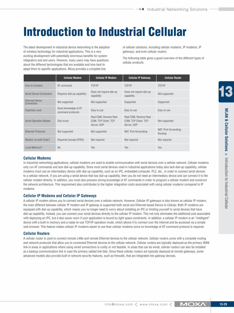
Introduction to Industrial CellularThe latest development in industrial device networking is the adoption of wireless technology for industrial applications. This is a very exciting development with potentially enormous benefits for system integrators and end users. However, many users may have questions about the different technologies that are available and how best to adapt them to specific applications. Moxa provides a complete line
In industrial networking applications, cellular modems are used to enable communication with serial devices over a cellular network. Cellular modems only run AT commands and lack dial-up capability. Since most serial devices used in industrial applications today also lack dial-up capability, cellular modems must use an intermediary device with dial-up capability, such as an IPC, embedded computer, PLC, etc., in order to connect serial devices to a cellular network. If you are using a serial device that has dial-up capability, then you do not need an intermediary device and can connect it to the cellular modem directly. In addition, you must also possess strong knowledge of AT commands in order to program a cellular modem and construct the network architecture. This requirement also contributes to the higher integration costs associated with using cellular modems compared to IP modems.
A cellular IP modem allows you to connect serial devices over a cellular network. However, Cellular IP gateways is also known as cellular IP modem, the main different between cellular IP modem and IP gateway is supported both serial and Ethernet-based Device to Cellular. Both IP modems are equipped with dial-up capability, which means you no longer need to worry about installing an IPC or limiting yourself to serial devices that have dial-up capability. Instead, you can connect your serial devices directly to the cellular IP modem. This not only eliminates the additional cost associated with deploying an IPC, but it also saves room if your application is bound by tight space constraints. In addition, a cellular IP modem is an “intelligent” device with a built-in memory and a ready-to-use TCP/IP operation mode, which allows it to connect over the Internet and be accessed via a simple web browser. This feature makes cellular IP modems easier to use than cellular modems since no knowledge of AT command protocol is required.
A cellular router is used to connect remote LANs and remote Ethernet devices to the cellular network. Cellular routers come with a complete routing and network protocols that allow you to connected Ethernet devices to the cellular network. Cellular routers are typically deployed as the primary WAN link in areas or applications where using wired connections is costly or not feasible. In areas that can be wired, cellular routers can also be installed as a backup communication link in case the primary cabled link fails. Since these cellular routers are typically deployed at remote gateways, some advanced models also provide built-in network security features, such as firewalls, that are integrated into gateway devices.
of cellular solutions, including cellular modems, IP modems, IP gateways, and even cellular routers.
The following table gives a good overview of the different types of cellular products:
Cellular Modem Cellular IP Modem Cellular IP Gateway Cellular Router
How to Connect AT command TCP/IP TCP/IP TCP/IP
Serial Device Connection Requires dial-up capabilityDoes not require dial-up capability
Does not require dial-up capability
Not supported
Ethernet Device Connection Not supported Not supported Supported Supported
Expertise LevelGood knowledge of AT command protocols
Easy to use Easy to use Easy to use
Serial Operation Modes Dial in/outReal COM, Reverse Real COM, TCP Client, TCP Server, UDP
Real COM, Reverse Real COM, TCP Client, TCP Server, UDP
Not supported
Ethernet Protocols Not supported Not supported NAT, Port-forwardingNAT, Port-forwarding, Routing
Modem on both Ends? Required (except GPRS) Not required Not required Not required
Local Memory? No Yes Yes Yes
Cellular Modems
Cellular IP Modems and Cellular IP Gateways
Cellular Routers
13-30 w w w. m o x a . c o m i n f o @ m o x a . c o m
WLAN & Cellular Solutions
WLAN
& Cellular Solutions >
Introduction to Industrial Cellular
13
Cellular ModemAn Intermediary device with dail-up capability is required to connect a serial device that LACKS dial-up capability
No Intermediary device is required to connect a serial device that HAS dail-up capability
LandlineCarrier
Cellular Modem or PSTN Modem
Cellular Modem ApplicationServer
IPCSerial Device
Serial Serial
Wirelesscarrier
Lacks dial-upcapability
Lacks dial-upcapability
Has dial-upcapability
LandlineCarrier
Cellular Modem or PSTN Modem
Cellular Modem ApplicationServer
Serial Device
Serial
Wirelesscarrier
Has dial-upcapability
Lacks dial-upcapability
Cellular Modems vs. Cellular IP ModemsCellular modems and cellular IP modems are vital components in industrial cellular machine-to-machine (M2M) networking. However, it may be difficult to differentiate between these two devices based on their names alone. The following pictures illustrate the differences between a cellular modem and a cellular IP modem to help you decide which device is most appropriate for your application.Cellular modems
and cellular IP modems are vital components in industrial cellular machine-to-machine (M2M) networking. However, it may be difficult to differentiate between these two devices based on their names alone. The following pictures illustrate the differences between a cellular modem and a cellular IP modem to help you decide which device is most appropriate for your application.
ApplicationServer
CellularIP-Modem
Legacy SerialDevice
Cellular IP Modem
Serial
Wirelesscarrier
Internet/IP WAN
With dial-up ability
No Intermediary device is required to connect a serial device that HAS dail-up capability
Industrial Networking Solutions
13-31i n f o @ m o x a . c o m w w w. m o x a . c o m
Introduction to Industrial CellularW
LAN &
Cellular Solutions >
13
Cellular Modems
Cellular IP Gateways
The OnCell G2100 supports the standard and extended Hayes* AT command set, in which AT is short for “attention code.” These commands form an industry standard language used to communicate with the modem. The modem can switch between one of two modes. When in “data mode,” the modem treats everything it receives from the intelligent device as data, and then sends it across the cellular network. When in “command mode,” data is interpreted as commands to the local modem.
The OnCell G3100 is assigned an IP address by your service provider (your “cellular ISP”). Outgoing TCP/IP connections are handled with Network Address Translation (NAT). This allows any number of local Ethernet devices to act as outgoing TCP/IP clients to access remote servers. However, the OnCell G3100 appears as a single IP address to the “public” Internet. This means that incoming connections must be forwarded manually, based on TCP port number, to the local Ethernet devices.
Virtual Modem mode is designed to run with operating systems that support AT commands to extend the distance between devices and modems that communicate through the RS-232 interface (Figure 1). In Figure 2 we show a setup that uses two device servers to extend the transmission distance. If this type of solution is not feasible, or is deemed inefficient, then greater efficiency can be achieved using Moxa’s OnCell IP gateway (Figure 3). By connecting a properly configured OnCell IP gateway’s Ethernet port to the computer’s Ethernet port, and installing the Moxa driver in the computer, it is possible to transmit data over the cellular network, even if the software running on the computer was originally designed to transmit data through a modem.
A major benefit of GSM technology is its support of short messages (SMS) for easy communication over the mobile network. With Moxa’s SMS Tunnel Mode, the OnCell G2100 modems allow users to expand applications at little or no extra cost. For example, SMS Tunnel Mode can be used to update the message on a highway display panel, place refill orders for vending machines, handle maintenance for remote rental equipment, or even help create an SMS alarm by directly transforming the text, binary, or unicode data from a legacy device to short message format, without using AT Commands. SMS Tunnel Mode is particularly suitable for devices that communicate infrequently or do not have access to the local network. Although SMS Tunnel Mode converts both ASCII and binary data to short messages transparently, a caller ID (phone number identification) design has been implemented to block messages sent from uncertified users, system broadcasts, and commercial SMS advertisements
AT Commands
Ethernet-based Device to Cellular
Virtual Modem Mode
SMS Tunnel Mode
SMS to Serial
SMS to Serial
SMS to Serial
SMS of ID#1
Serial to SMS SMS to Serial
SMS TunnelNo AT Commands Required
Uncerified ID
Broadcast
Serial to SMS
SMS of ID#2
PC
LED Pane
PC/ Controlleror Serial Devices
SMS to Serial withoutAT Commands
OnCell G2100OnCell G2100
OnCell G2100
Daller ID Verification
N
OnCell G2100 OnCell G2100
OnCell G2100
EthernetSerial Site
Host
Wirelesscarrier
Internet
Ho
Figure 1 Figure 2 Figure 3
AT command AT command AT command
Ethernet
Ethernet
DeviceServer
Modem
Modem
RS-232
RS-23232
M
dem
13-32 w w w. m o x a . c o m i n f o @ m o x a . c o m
WLAN & Cellular Solutions
WLAN
& Cellular Solutions >
Introduction to Industrial Cellular
13
OnCell Central Management Software
Cellular IP Modems
In the cellular world, most service providers only offer private IP addresses to mobile devices due to the limited availability of public addresses. Mobile devices configured with a private IP address can access resources on the Internet, but the mobile devices cannot be managed or accessed directly from the Internet since the private IP address is hidden.
The mechanism we developed uses a server configured with a public IP address to solve this private IP problem. The OnCell Central software installed in the server accepts connections from both Ethernet and serial mobile devices and remote hosts. Once a connection is established, the mobile device and the remote host can communicate with each other over the pre-established connection.
The OnCell G3100 supports three types of connection mode for GSM/GPRS/EDGE communication: (1) Always ON, (2) Inactivity Timeout, and (3) Remote Host Recovered. These connection modes provide users with more connection options for GSM/GPRS/EDGE, and have the potential to reduce the total cost of applications. The GPRS “Always ON” mode maintains connectivity between the OnCell G3100 and the remote device. That is, it enables a fail-safe mechanism that re-establishes the connection when the remote device is down.
Choice of Connection Type
Moreover, if the “Inactivity Timeout” mode is enabled, the connection will disconnect if data has not been transmitted between the serial device and cellular network during a user-specified time period, or the remote Ethernet host crashes. The OnCell 3100 will keep pinging the remote host over the Ethernet every 3 seconds after powering on. After failing to connect 5 times in a row, the data from the serial device will be sent through the GSM connection.
2. Reverse Real COM to PC’s domain nameWith Reverse Real COM mode, you can connect to a PC host using the PC’s IP address. You can also connect to your PC host with the PC’s domain name (provided you have one).
Any IP Domain Name
data data
CellularNetwork
Domain name
1. Reverse Real COM to PC’s IP addressMost cellular service providers only provide customers with a dynamic private IP address, which means that the OnCell G3100 will only obtain an IP address once it is connected to the cellular network. Reverse Real COM is a great feature that allows a PC host to access an OnCell G3100 configured with private IP address.
Types of Reverse Real COM Connection
Any IP Fixed public IP
data data
CellularNetwork
IP address
Public IP
Private IP
Private IP
OnCell CentralServer
Main Office
Site
Main OfficeEthernetSerial
Reverse Real COM mode uses a mechanism similar to port mapping to enable remote devices that are using a private IP address to remain accessible to external hosts. When this mode is enabled, the Moxa driver that comes with the device establishes a transparent connection from the device to the remote host by mapping the device’s serial port to a local COM port on the remote host. Reverse Real COM mode supports up to 2 simultaneous connections that enable serial devices to send data to 2 hosts simultaneously. 1. Send a request for connectionHost
COM4=MAC add.Moxa’s Driver
RS-232/422/485
2. Transparent TCP connection established
Internet
Device
Wirelesscarrier
Reverse Real COM Mode
Industrial Networking Solutions
13-33i n f o @ m o x a . c o m w w w. m o x a . c o m
Introduction to Industrial CellularW
LAN &
Cellular Solutions >
13
Cellular Routers
Moxa’s cellular routers create a secure WAN connection via an Ethernet-to-cellular interface for remote mission-critical data operations. The routers provide secure cellular GSM/GPRS or UMTS/HSDPA connections for reliable primary and backup network connectivity to industrial automation devices, such as SCADA devices, programmable logic controllers (PLCs), and remote terminal units (RTUs). The OnCell 5004 features industrial hardware components that include a terminal block for power, a screw-on type power connector, and a wall-mount accessory. The OnCell 5004 also offers local intelligence with features such as network routing, persistent connections, firewall, and secure integrated remote management software package. Advanced features include TCP/UDP, DHCP support, NAT, port forwarding, and access control lists.
Remote Side Control Center
LAN
Wirelesscarrier
Internet
13-34 w w w. m o x a . c o m i n f o @ m o x a . c o m
WLAN & Cellular Solutions
WLAN
& Cellular Solutions >
OnCell 5004/5104-HSDPA
13
OnCell 5004/5104-HSDPAIndustrial tri-band UMTS/HSDPA high speed cellular routers
Universal tri-band UMTS/HSDPA 850/1900/2100 MHz ›Industrial primary and backup wireless WAN connectivity ›Connect up to 4 10/100BaseT(X) devices ›Redundant DC power inputs ›2 digital inputs and 1 relay output (OnCell 5104-HSDPA only) ›
The OnCell 5004/5104-HSDPA are high-performance industrial grade cellular routers that allow up to 4 Ethernet-based devices to simultaneously use a single cellular data account for primary or backup network connectivity to remote sites and devices. Both products provide the functionality of a cellular router, firewall, and switch in one device, and are the industry’s first standalone platforms of this type. The difference between the OnCell 5004-HSDPA and OnCell 5104-HSDPA is that the OnCell 5104-HSDPA comes with a built-in relay output that can be configured to indicate the priority of
events when notifying or warning engineers in the field, and the two digital inputs allow you to connect basic I/O devices, such as sensors, to the cellular network. The OnCell 5004-HSDPA can be placed on a desktop or wall-mounted, whereas the OnCell 5104-HSDPA has an IA design and can be attached to a DIN-rail. Both products use 12 to 48 VDC power inputs with a screw-on design for greater reliability, and the Ethernet ports come with 1.5 KV magnetic isolation protection to keep your system safe from unexpected electrical discharges.
Overview
Specifi cations
Cellular InterfaceStandards: UMTS/HSDPABand Options:Tri-band UMTS/HSDPA 850/1900/2100 MHzQuad-band GSM/GPRS/EDGE 850/900/1800/1900 MHzEDGE Multi-slot Class: Class 10EDGE Terminal Device Class: Class BGPRS Multi-slot Class: Class 10GPRS Terminal Device Class: Class BGPRS Coding Schemes: CS1 to CS4Tx Power:GSM900: 2 WUMTS/HSDPA: 0.25 WEDGE900: 0.5 WEDGE1800: 0.4 WGSM1800: 1 WWAN InterfaceNumber of Ports: 1Ethernet: 10/100 Mbps, RJ45 connector, Auto MDI/MDIXMagnetic Isolation Protection: 1.5 KV built-inLAN InterfaceNumber of Ports: 4Ethernet: 10/100 Mbps, RJ45 connector, auto MDI/MDIXMagnetic Isolation Protection: 1.5 KV built-inSIM InterfaceNumber of SIMs: 2SIM Control: 3 V
I/O Interface (OnCell 5104-HSDPA only)Alarm Contact: 1 relay output with current carrying capacity of 1A @ 24 VDCDigital Inputs: 2 electrically isolated inputs• +13 to +30 V for state “1” (On)• +3 to -30 V for state “0” (Off)SoftwareNetwork Protocols: UDP/TCP, SNTP, ICMP, DDNS, DHCP/BOOTP, PPPoE, PPP, DNS Relay, HTTPS, TelnetRouter/Firewall: NAT, port forwarding, routingAuthentication: Local user-name and passwordSecurity: IP fi lteringPhysical CharacteristicsHousing: Aluminum, providing IP30 protectionWeight:OnCell 5004-HSDPA: 505±5 gOnCell 5104-HSDPA: 645±5 gDimensions:OnCell 5004-HSDPA: 158 x 103 x 34 mm (6.22 x 4.06 x 1.34 in)OnCell 5104-HSDPA: 160 x 103 x 50 mm (6.30 x 4.06 x 1.97 in)Environmental LimitsOperating Temperature: -30 to 55°C (-22 to 131°F)Operating Humidity: 5 to 95% RHStorage Temperature: -40 to 75°C (-40 to 167°F)Power RequirementsNumber of Power Inputs: 1 terminal block, 1 power jackInput Voltage: 12 to 48 VDCData Link: 335 to 1185 mA (peak) @ 12 V
Coming
Soon
The certifi cation logos shown here apply to some or all of the products in this section. For details, see “Regulatory Approvals” under “Specifi cations” below.
OnCell 5004-HSDPA OnCell 5104-HSDPA
Industrial Networking Solutions
13-35i n f o @ m o x a . c o m w w w. m o x a . c o m
Available ModelsOnCell 5004-HSDPA: 4-port 10/100M Ethernet to UMTS/HSDPA cellular routerOnCell 5104-HSDPA: 4-port 10/100M Ethernet to UMTS/HSDPA cellular router, IA design
Optional Accessories (can be purchased separately)DC Power Supply (screw-on): See Appendix ADC Power Supply (standard): See Appendix APower Jack to Terminal Block Cable: See Appendix AANT-WCDMA-ASM-1.5: Omni 1.5dBi/10cm, magnetic SMA tri-band antenna (impedance = 50 ohms)ANT-WCDMA-AHSM-04-2.5m: Omni 4dBi/11cm, magnetic SMA tri-band antenna, 2.5 m (impedance = 50 ohms)
35 mm (1.38 in)158 mm (6.22 in)
50.1 mm(1.97 in)160 mm (6.30 in)
13-36 w w w. m o x a . c o m i n f o @ m o x a . c o m
WLAN & Cellular Solutions
WLAN
& Cellular Solutions >
OnCell 5004/5104
13
Industrial quad-band GSM/GPRS cellular routersUniversal quad-band GSM/GPRS 850/900/1800/1900 MHz ›Industrial primary and backup wireless WAN connectivity ›Connect up to 4 10/100BaseT(X) devices ›Redundant DC power inputs ›2 digital inputs and 1 relay output (OnCell 5104 only) ›
The OnCell 5004/5104 are high-performance industrial grade cellular routers that allow up to 4 Ethernet-based devices to simultaneously use a single cellular data account for primary or backup network connectivity to remote sites and devices. Both products provide the functionality of a cellular router, firewall, and switch in one device, and are the industry’s first standalone platform of this type. The difference between the OnCell 5004 and OnCell 5104 is that the OnCell 5104 comes with a built-in relay output that can be configured to indicate
the priority of events when notifying or warning engineers in the field, and the two digital inputs allow you to connect basic I/O devices, such as sensors, to the cellular network. The OnCell 5004 can be placed on a desktop or wall-mounted, whereas the OnCell 5104 has an IA design and can be attached to a DIN-rail. Both products use 12 to 48 VDC power inputs with a screw-on design for greater reliability, and the Ethernet ports come with 1.5 KV magnetic isolation protection to keep your system safe from unexpected electrical discharges.
Overview
Specifi cationsCellular InterfaceStandards: GSM/GPRSBand Options: Quad-band 850/900 and 1800/1900 MHzGPRS Multi-slot Class: Class 10GPRS Terminal Device Class: Class BGPRS Coding Schemes: CS1 to CS4Tx Power: 1 watt GSM 1800/1900, 2 watts EGSM 850/900WAN InterfaceNumber of Ports: 1Ethernet: 10/100 Mbps, RJ45 connector, Auto MDI/MDIXMagnetic Isolation Protection: 1.5 KV built-inLAN InterfaceNumber of Ports: 4Ethernet: 10/100 Mbps, RJ45 connector, auto MDI/MDIXMagnetic Isolation Protection: 1.5 KV built-inSIM InterfaceNumber of SIMs: 2SIM Control: 3 V
I/O Interface (OnCell 5104 only)Alarm Contact: 1 relay output with current carrying capacity of 1A @ 24 VDCDigital Inputs: 2 electrically isolated inputs• +13 to +30 V for state “1” (On)• +3 to -30 V for state “0” (Off)SoftwareNetwork Protocols: UDP/TCP, SNTP, ICMP, DDNS, DHCP/BOOTP, PPPoE, PPP, DNS Relay, HTTPS, TelnetRouter/Firewall: NAT, port forwarding, routingAuthentication: Local user-name and passwordSecurity: IP fi ltering
Physical CharacteristicsHousing: Aluminum, providing IP30 protectionWeight:OnCell 5004: 505±5 gOnCell 5104: 645±5 g Dimensions:OnCell 5004: 158 x 103 x 34 mm (6.22 x 4.06 x 1.34 in)OnCell 5104: 160 x 103 x 50 mm (6.30 x 4.06 x 1.97 in)Environmental LimitsOperating Temperature: -30 to 55°C (-22 to 131°F)Operating Humidity: 5 to 95% RHStorage Temperature: -40 to 75°C (-40 to 167°F)Power RequirementsNumber of Power Inputs: 1 terminal block, 1 power jackInput Voltage: 12 to 48 VDCData Link: 335 to 1185 mA (peak) @ 12 VRegulatory ApprovalsSafety: UL: UL60950RF:FCC Part22HFCC PART24EEN301 489-1EN301 489-7EN301 511EMC:CE: EN55022 Class A / EN55024FCC: FCC part 15 subpart B, Class AEN61000-4-2 (ESD) Level 4EN61000-4-3 (RS) Level 3EN61000-4-4 (EFT) Level 4EN61000-4-5 (Surge) Level 3EN61000-4-8 Level 3EN61000-4-12 Level 3
OnCell 5004/5104
OnCell 5004 OnCell 5104
The certifi cation logos shown here apply to some or all of the products in this section. For details, see “Regulatory Approvals” under “Specifi cations” below.
GSM/GPR
Coming
Soon
Industrial Networking Solutions
13-37i n f o @ m o x a . c o m w w w. m o x a . c o m
Available ModelsOnCell 5004: 4-port 10/100M Ethernet to GSM/GPRS cellular routerOnCell 5104: 4-port 10/100M Ethernet to GSM/GPRS cellular router, IA design
OnCell 5004
OnCell 5104
35 mm (1.38 in)158 mm (6.22 in)
50.1 mm(1.97 in)160 mm (6.30 in)
WarrantyWarranty Period: 5 yearsDetails: See www.moxa.com/warranty
Optional Accessories (can be purchased separately)DC Power Supply (screw-on): See Appendix ADC Power Supply (standard): See Appendix APower Jack to Terminal Block Cable: See Appendix AANT-CQB-AHSM-00-3m: Omni 0dBi/10cm, magnetic SMA quad-band antenna (impedance = 50 ohms), 3 mANT-CQB-AHSM-03-3m: Omni 3dBi/25cm, magnetic SMA quad-band antenna (impedance = 50 ohms), 3 mANT-CQB-AHSM-05-3m: Omni 5dBi/37cm, magnetic SMA quad-band antenna (impedance = 50 ohms), 3 m
13-38 w w w. m o x a . c o m i n f o @ m o x a . c o m
WLAN & Cellular Solutions
WLAN
& Cellular Solutions >
OnCell G3110/3150-HSDPA
13
OnCell G3110/3150-HSDPAIndustrial tri-band UMTS/HSDPA IP gateways
Universal tri-band UMTS/HSDPA 850/900/2100 MHz ›Bring 10/100Base-T and serial devices together ›Choice of operation modes, including TCP Server, TCP Client, ›UDP, Real COM, Reverse Real COM, and RFC2217
Secure modes for TCP Server, TCP Client, Real COM, and Re- ›verse Real COM
Redundant DC power inputs ›Two digital inputs and 1 relay output ›Centralize private IP management software ›DIN-Rail ›
The OnCell G3100-HSDPA series of high-speed industrial-grade IP gateways are intelligent and fully-featured wireless communication platforms that connect your legacy serial devices over a cellular TCP/IP network. The OnCell G3100-HSDPA series offers connectivity to all tri HSDPA/UMTS frequency bands, as well as all quad GSM/GPRS/EDGE frequency bands (850/900/1800/1900 MHz), used in Europe and the United States, allowing seamless global roaming on the best available network. The OnCell G3100-HSDPA offers versatile operation modes
such as Reverse Real COM mode for cellular network structures (to handle the IP address issue), which automatically generates a virtual COM port to match serial ports, allowing you to communicate with remote serial devices. The OnCell G3100-HSDPA also comes with a built-in relay output that can be configured to indicate the priority of events when notifying or warning engineers in the field. Two digital inputs also allow you to connect basic I/O devices, and the OnCell G3100-HSDPA comes with redundant power inputs to assure non-stop operation.
Overview
Specifi cations
OnCell G3110-HSDPA OnCell G3150-HSDPA
Cellular InterfaceStandards: GSM/GPRS/EDGEBand Options: Quad-band 850/900 and 1800/1900 MHzEDGE Multi-slot Class: Class 10GPRS Multi-slot Class: Class 10GPRS Terminal Device Class: Class BGPRS Coding Schemes: CS1 to CS4Tx Power: 1 watt GSM 1800/1900, 2 watts EGSM 850/900LAN InterfaceNumber of Ports: 1Ethernet: 10/100 Mbps, RJ45 connector, Auto MDI/MDIXMagnetic Isolation Protection: 1.5 KV built-inSIM InterfaceNumber of SIMs: 1SIM Control: 3 VSerial InterfaceNumber of Ports: 1Serial Standards:G3110: RS-232 (DB9 male connector)G3150: RS-232 (DB9 male connector), RS-422/485 (5-pin terminal block connector)ESD Protection: 15 KVPower EFT/Surge Protection: 2 KVSerial Communication ParametersData Bits: 5, 6, 7, 8Stop Bits: 1, 1.5, 2 (when parity = None)Parity: None, Even, Odd, Space, Mark
Flow Control: RTS/CTS, XON/XOFFBaudrate: 50 bps to 921.6 KbpsSerial SignalsRS-232: TxD, RxD, RTS, CTS, DTR, DSR, DCD, GNDRS-422: Tx+, Tx-, Rx+, Rx-, GNDRS-485-4w: Tx+, Tx-, Rx+, Rx-, GNDRS-485-2w: Data+, Data-, GNDI/O InterfaceAlarm Contact: 1 relay output with current carrying capacity of 1A @ 24 VDCDigital Inputs: 2 electrically isolated inputs• +13 to +30 V for state “1” (On)• +3 to -30 V for state “0” (Off)SoftwareNetwork Protocols: ICMP, TCP/IP, UDP, DHCP, Telnet, DNS, SNMP, HTTP, SMTP, HTTPS, SNTP, ARP, SSLRouter/Firewall: NAT, port forwardingAuthentication: Local user-name and passwordSecurity: Accessible IP listOperation Modes: Real COM, Secure Real COM, TCP Server, Secure TCP Server, TCP Client, Secure TCP Client, UDP, RFC2217, Ethernet Modem, Virtual Modem, SMS TunnelConfi guration and Management Options: SNMP MIB-II, SNMP Private MIB, SNMPv1/v2c/v3, DDNS, IP Report, Web/Telnet/Serial-Console/SSHUtilities: Provided for Windows 95/98/ME, Windows NT, Windows 2000/XP/2003/Vista/Server-2008, Windows XP/2003/Vista/Server-2008 x64 Edition
The certifi cation logos shown here apply to some or all of the products in this section. For details, see “Regulatory Approvals” under “Specifi cations” below.
Industrial Networking Solutions
13-39i n f o @ m o x a . c o m w w w. m o x a . c o m
13
WLAN
& Cellular Solutions >
OnCell G3110/3150-HSDPA
Ordering InformationPackage Checklist
OnCell IP Gateway• Rubber SMA antenna• DIN-Rail Kit• 5-pin Terminal Block (screw type)• 10-pin Terminal Block (screw type)• Document and Software CD• Quick Installation Guide (printed)• Warranty Card•
Available ModelsOnCell G3110-HSDPA: 1-port RS-232 to UMTS/HSDPA IP gatewayOnCell G3150-HSDPA: 1-port RS-232/422/485 to UMTS/HSDPA IP gateway
Optional Accessories (can be purchased separately)DC Power Supply: See Appendix APower Jack to Terminal Block Cable: See Appendix AANT-WCDMA-ASM-1.5: Omni 1.5dBi/10cm, magnetic SMA tri-band antenna (impedance = 50 ohms)ANT-WCDMA-AHSM-04-2.5m: Omni 4dBi/11cm, magnetic SMA tri-band antenna, 2.5 m (impedance = 50 ohms)
138.
05 m
m (5
.4 in
)12
5.50
mm
(4.9
in)
92.50 mm (3.6 in)100.70 mm (3.96 in)28.00 mm (1.1 in)
Windows Real COM Drivers: Windows 95/98/ME, Windows NT, Windows 2000/XP/2003/Vista/Server 2008, Windows XP/2003/Vista/Server 2008 x64 EditionFixed TTY Drivers: SCO Unix, SCO OpenServer 5, SCO OpenServer 6, UnixWare 7, SVR4.2, QNX 4.25, QNX 6, Solaris 10, FreeBSD 5, FreeBSD 6Linux Real TTY Drivers: Linux kernels 2.2.x, 2.4.x, 2.6.xManagement SoftwareOnCell Central Manager: Centralized management solution for accessing private IPs from the InternetPhysical CharacteristicsHousing: Aluminum, providing IP30 protectionWeight: 440±5 gDimensions: 28 x 126 x 93 mm (1.10 x 4.96 x 3.66 in)Environmental LimitsOperating Temperature: -30 to 55°C (-22 to 131°F)Operating Humidity: 5 to 95% RHStorage Temperature: -40 to 75°C (-40 to 167°F)Power RequirementsNumber of Power Inputs: 2 (terminal block)Input Voltage: 12 to 48 VDCData Link: 335 to 1185 mA (peak) @ 12 V
Regulatory ApprovalsSafety:UL: UL60950RF:FCC Part22HFCC PART24EEN301 489-1EN301 489-7EN301 511EMC:CE: EN55022 Class A / EN55024FCC: FCC part 15 subpart B, Class AEN61000-4-2 (ESD) Level 4EN61000-4-3 (RS) Level 3EN61000-4-4 (EFT) Level 4EN61000-4-5 (Surge) Level 3EN61000-4-8 Level 3EN61000-4-12 Level 3ReliabilityMTBF (meantime between failures): 380,459 hours (G3110-HSD-PA/G3150-HSDPA)WarrantyWarranty Period: 5 yearsDetails: See www.moxa.com/warranty
13-40 w w w. m o x a . c o m i n f o @ m o x a . c o m
WLAN & Cellular Solutions
WLAN
& Cellular Solutions >
OnCell G3110/3150
13
OnCell G3110/3150Industrial quad-band GSM/GPRS/EDGE IP gateways
Connect both Ethernet and serial devices to cellular networks ›Universal quad-band GSM/GPRS/EDGE-850/900/1800/1900-MHz ›Choice of operation modes, including TCP Server, TCP Client, ›UDP, Real COM, and RFC2217
Secure modes for TCP Server, TCP Client, and Real COM ›Redundant DC power input ›2 digital inputs and 1 relay output ›Centralize private IP management software ›DIN-Rail mounting ›
The OnCell G3110 and G3150 industrial RS-232 and RS-232/422/485 GSM/GPRS/EDGE IP gateway are designed to transmit data transparently over GSM/GPRS/EDGE cellular networks. The Real COM operation mode automatically generates a virtual COM port to match serial ports supported by the OnCell G3110/3150, allowing
you to communicate with remote serial devices. The OnCell G3100 can transmit data from both serial devices and Ethernet devices to a WAN interface. To achieve this Ethernet-to-cellular function, the OnCell G3100 works in a manner similar to a router. All Ethernet devices connected to the OnCell’s LAN port will be hidden from the outside world with OnCell’s NAT function.
Overview
Specifi cations
Cellular InterfaceStandards: GSM/GPRS/EDGEBand Options: Quad-band 850/900 and 1800/1900 MHzEDGE Multi-slot Class: Class 12GPRS Multi-slot Class: Class 12GPRS Terminal Device Class: Class BGPRS Coding Schemes: CS1 to CS4Tx Power: 1 watt GSM 1800/1900, 2 watts EGSM 850/900LAN InterfaceNumber of Ports: 1Ethernet: 10/100 Mbps, RJ45 connector, Auto MDI/MDIXMagnetic Isolation Protection: 1.5 KV built-inSIM InterfaceNumber of SIMs: 1SIM Control: 3 VSerial InterfaceNumber of Ports: 1Serial Standards:G3110: RS-232 (DB9 male connector)G3150: RS-232 (DB9 male connector), RS-422/485 (5-pin terminal block connector)ESD Protection: 15 KVPower EFT/Surge Protection: 2 KVSerial Communication ParametersData Bits: 5, 6, 7, 8Stop Bits: 1, 1.5, 2 (when parity = None)Parity: None, Even, Odd, Space, MarkFlow Control: RTS/CTS, XON/XOFFBaudrate: 50 bps to 921.6 Kbps
Serial SignalsRS-232: TxD, RxD, RTS, CTS, DTR, DSR, DCD, GNDRS-422: Tx+, Tx-, Rx+, Rx-, GNDRS-485-4w: Tx+, Tx-, Rx+, Rx-, GNDRS-485-2w: Data+, Data-, GNDI/O InterfaceAlarm Contact: 1 relay output with current carrying capacity of 1A @ 24 VDCDigital Inputs: 2 electrically isolated inputs• +13 to +30 V for state “1” (On)• +3 to -30 V for state “0” (Off)SoftwareNetwork Protocols: ICMP, TCP/IP, UDP, DHCP, Telnet, DNS, SNMP, HTTP, SMTP, HTTPS, SNTP, ARP, SSLRouter/Firewall: NAT, port forwardingAuthentication: Local user-name and passwordSecurity: Accessible IP listOperation Modes: Real COM, Secure Real COM, TCP Server, Secure TCP Server, TCP Client, Secure TCP Client, UDP, RFC2217, Ethernet Modem, Virtual Modem, SMS TunnelConfi guration and Management Options: SNMP MIB-II, SNMP Private MIB, SNMPv1/v2c/v3, DDNS, IP Report, Web/Telnet/Serial-Console/SSHUtilities: Provided for Windows 95/98/ME, Windows NT, Windows 2000/XP/2003/Vista/Server-2008, Windows XP/2003/Vista/Server-2008 x64 EditionWindows Real COM Drivers: Windows 95/98/ME, Windows NT, Windows 2000/XP/2003/Vista/Server 2008, Windows XP/2003/Vista/Server 2008 x64 Edition
The certifi cation logos shown here apply to some or all of the products in this section. For details, see “Regulatory Approvals” under “Specifi cations” below.
Industrial Networking Solutions
13-41i n f o @ m o x a . c o m w w w. m o x a . c o m
13
WLAN
& Cellular Solutions >
OnCell G3110/3150
Ordering InformationPackage Checklist
OnCell IP gateway• Rubber SMA antenna• DIN-Rail kit• 5-pin terminal block (screw type)• 10-pin terminal block (screw type)• Document and Software CD• Quick Installation Guide (printed)• Warranty Card•
Available ModelsOnCell G3110: 1-port RS-232 to GSM/GPRS/EDGE IP gatewayOnCell G3150: 1-port RS-232/422/485 to GSM/GPRS/EDGE IP gateway
Fixed TTY Drivers: SCO Unix, SCO OpenServer 5, SCO OpenServer 6, UnixWare 7, SVR4.2, QNX 4.25, QNX 6, Solaris 10, FreeBSD 5, FreeBSD 6Linux Real TTY Drivers: Linux kernels 2.2.x, 2.4.x, 2.6.xManagement SoftwareOnCell Central Manager: Centralized management solution for accessing private IPs from the InternetPhysical CharacteristicsHousing: Aluminum, providing IP30 protectionWeight: 440±5 gDimensions: 28 x 126 x 93 mm (1.10 x 4.96 x 3.66 in)Environmental LimitsOperating Temperature: -30 to 55°C (-22 to 131°F)Operating Humidity: 5 to 95% RHStorage Temperature: -40 to 75°C (-40 to 167°F)Power RequirementsInput Voltage: 12 to 48 VDCData Link: 335 to 1185 mA (peak) @ 12 V
Regulatory ApprovalsSafety:UL: UL60950RF:FCC Part22HFCC PART24EEN301 489-1EN301 489-7EN301 511PTCRBEMC:CE: EN55022 Class A / EN55024FCC: FCC part 15 subpart B, Class AEN61000-4-2 (ESD) Level 4EN61000-4-3 (RS) Level 3EN61000-4-4 (EFT) Level 4EN61000-4-5 (Surge) Level 3EN61000-4-8 Level 3EN61000-4-12 Level 3ReliabilityMTBF (meantime between failures): G3110/G3150: 339045 hoursWarrantyWarranty Period: 5 yearsDetails: See www.moxa.com/warranty
Optional Accessories (can be purchased separately)DC Power Supply: See Appendix APower Jack to Terminal Block Cable: See Appendix A Quad-band Antennas (impedance = 50 ohms)ANT-CQB-AHSM-00-3m: Omni 0dBi/10cm, magnetic SMA antenna, 3 mANT-CQB-AHSM-03-3m: Omni 3dBi/25cm, magnetic SMA antenna, 3 mANT-CQB-AHSM-05-3m: Omni 5dBi/37cm, magnetic SMA antenna, 3 m
13-42 w w w. m o x a . c o m i n f o @ m o x a . c o m
WLAN & Cellular Solutions
WLAN
& Cellular Solutions >
OnCell G3111/3151/3211/3251
13
OnCell G3111/3151/3211/32511 and 2-port RS-232 or RS-232/422/485 cellular IP modems
Universal quad-band GSM/GPRS 850/900/1800/1900 MHz ›Choice of operation modes, including TCP Server, TCP Client, UDP, ›Real COM, and Reverse Real COM
Management Software: Private IP management › with OnCell Central
Choice of confi guration methods, including web console, serial ›console, and Telnet
Desktop or DIN-Rail installation ›
The OnCell G3111/G3151/G3211/G3251 are cost effective cellular IP modems that can conveniently and transparently connect up to two devices to a cellular network, allowing you to network your existing serial devices with only basic configuration. OnCell provides versatile operation modes that make data transmission between the serial and cellular interfaces bi-directional. The G3111/G3151/G3211/G3251
cellular IP modems are compact, and can be used on a desktop or mounted on a DIN-rail. The products come with a 12 to 48 VDC power input and have 2 KV EFT/Surge protection to allow the use of different types of field power sources. The serial ports are also protected by 15 KV ESD line protection to keep your system safe from unexpected electrical discharges.
Overview
Specifi cations
The certifi cation logos shown here apply to some or all of the products in this section. For details, see “Regulatory Approvals” under “Specifi cations” below.
Cellular InterfaceStandards: GSM/GPRSBand Options: Quad-band 850/900 and 1800/1900 MHzGPRS Multi-slot Class: Class 10GPRS Terminal Device Class: Class BGPRS Coding Schemes: CS1 to CS4Tx Power: 1 watt GSM 1800/1900, 2 watts EGSM 850/900SIM Control: 3 VLAN InterfaceNumber of Ports: 1Ethernet: 10/100 Mbps, RJ45 connector, Auto MDI/MDIXMagnetic Isolation Protection: 1.5 KV built-inSIM InterfaceNumber of SIMs: 1SIM Control: 3 VSerial InterfaceNumber of Ports: 1 or 2Serial Standards:G3111: 1 RS-232 portG3151: 1 RS-422/485 portG3211: 2 RS-232 portsG3251: 2 RS-422/485 portsESD Protection: 15 KVPower EFT/Surge Protection: 2 KVSerial Communication ParametersData Bits: 5, 6, 7, 8Stop Bits: 1, 1.5, 2 (when parity = None)Parity: None, Even, Odd, Space, Mark
Flow Control: RTS/CTS, XON/XOFFBaudrate: 50 bps to 921.6 KbpsSerial SignalsRS-232: TxD, RxD, RTS, CTS, DTR, DSR, DCD, GNDRS-422: Tx+, Tx-, Rx+, Rx-, GNDRS-485-4w: Tx+, Tx-, Rx+, Rx-, GNDRS-485-2w: Data+, Data-, GNDSoftwareNetwork Protocols: ICMP, TCP/IP, UDP, DHCP, Telnet, DNS, SNMP, HTTP, HTTPS, SMTP, SNTP, ARPAuthentication: Local user-name and passwordSecurity: Accessible IP listOperation Modes: Real COM, TCP Server, TCP Client, UDP, SMS Tunnel, Reverse Real COMConfi guration and Management Options: SNMP MIB-II, v3, DDNS, IP Report, Web/Telnet/Serial Console, Serial LoggingUtilities: Provided for Windows 95/98/ME, Windows NT, Windows 2000/XP/2003/Vista/Server-2008, WindowsXP/2003/Vista/Server-2008 x64Windows Real COM Drivers: Windows 95/98/ME, Windows NT, Windows 2000/XP/2003/Vista/Server-2008, Windows XP/2003/Vista/Server-2008 x64Management SoftwareOnCell Central Manager: Centralized management solution for accessing private IPs from the Internet
Coming
Soon
Industrial Networking Solutions
13-43i n f o @ m o x a . c o m w w w. m o x a . c o m
13
WLAN
& Cellular Solutions >
OnCell G3111/3151/3211/3251
Ordering InformationPackage Checklist
OnCell IP Modem• Rubber SMA antenna• DC Power Supply (screw-on)• DIN-Rail Kit• Rubber stand• Document and Software CD• Quick Installation Guide (printed)• Warranty Card•
Physical CharacteristicsHousing: Aluminum, providing IP30 protectionWeight:OnCell G3111/G3151: 165±5 g OnCell G3211/G3251: 185±5 gDimensions: 111 x 77 x 26 mm (4.37 x 3.03 x 1.02 in)Environmental LimitsOperating Temperature: -30 to 55°C (-22 to 131°F)Operating Humidity: 5 to 95% RHStorage Temperature: -40 to 75°C (-40 to 167°F)Power RequirementsNumber of Power Inputs: 1 power jackInput Voltage: 12 to 48 VDCData Link: 335 to 900 mA (peak) @ 12 V
Regulatory ApprovalsRF:EN301 489-1EN301 489-7EN301 511EMC:CE: EN55022 Class A / EN55024FCC: FCC part 15 subpart B, Class AEN61000-4-2 (ESD) EN61000-4-3 (RS) EN61000-4-4 (EFT) EN61000-4-5 (Surge) EN61000-4-8 EN61000-4-12 WarrantyWarranty Period: 5 yearsDetails: See www.moxa.com/warranty
Available ModelsOnCell G3111: 1-port RS-232 to GSM/GPRS IP modemOnCell G3151: 1-port RS-232/422/485 to GSM/GPRS IP modemOnCell G3211: 2-port RS-232 to GSM/GPRS IP ModemOnCell G3251: 2-port RS-232/422/485 to GSM/GPRS IP Modem
Optional Accessories (can be purchased separately)DC Power Supply (screw-on): See Appendix AANT-CQB-AHSM-00-3m: Omni 0dBi/10cm, magnetic SMA quad-band antenna (impedance = 50 ohms), 3 mANT-CQB-AHSM-03-3m: Omni 3dBi/25cm, magnetic SMA quad-band antenna (impedance = 50 ohms), 3 mANT-CQB-AHSM-05-3m: Omni 5dBi/37cm, magnetic SMA quad-band antenna (impedance = 50 ohms), 3 m
Dimensions
77 mm (3.03 in)11
1 m
m (4
.37
in)
100 mm (3.94 in) 26 mm(1.02 in)
OnCell G3211, OnCell G3251
OnCell G3111, OnCell G3151
13-44 w w w. m o x a . c o m i n f o @ m o x a . c o m
Quad-band GSM/GPRS 850/900/1800/1900 MHz ›Separate RS-232 and RS-422/485 serial interfaces (G2150I only) ›2.5 KV RMS isolation for 1 min. for all serial signals (G2150I only) ›Extended operating temperature from -30 to 75°C (G2110-T only) ›Vertical IP30 housing with SIM card protection ›LED indicators for GSM/GPRS, data transmission, and signal level ›DIN-Rail and wall mounting ›SMS Tunnel Mode provided ›
The OnCell G2100 Series of industrial quad-band GSM/GPRS modems are designed to transmit data and short messages (SMS) over GSM/GPRS mobile networks. The modems can be used to increase the efficiency of maintenance and communication, but do not require extensive training. In addition, the modems can be mounted on a DIN-rail or wall. The OnCell G2100 modems accept a 12 to 48 VDC power input, making them suitable for use with a variety of field power sources. The serial ports feature 15 KV ESD line protection to
protect the products from harmful electrical discharge, and separate RS-232 and RS-422/485 interfaces are built into the OnCell G2150I, each with 2.5 KV RMS isolation protection for one minute. The two serial interfaces on the OnCell G2150I make it ideal for attaching all kinds of devices, such as stand-alone controllers, PC COM ports, and multi-dropped electric meters. In addition, the OnCell G2110-T has an extended operating temperature (-40 to 75°C) design that makes it suitable for heavy industrial use.
Overview
Specifi cations
Cellular InterfaceStandards: GSM and GPRSBand Options: Quad-band 850/900/1800/1900 MHzGPRS Multi-slot Class: Class 10GPRS Terminal Device Class: Class BGPRS Coding Schemes: CS1 to CS4CSD Data Transmission Rate: Up to 14,400 bpsTx Power: 1 watt GSM1800/1900, 2 watts EGSM 900/GSM 850SIM InterfaceNumber of SIMs: 1SIM Control: 3 VSerial InterfaceNumber of Ports: 1Serial Standards:G2110: RS-232 (DB9 female connector)G2150I: RS-232 (DB9 female connector), RS-422/485 (5-pin terminal block connector)ESD Protection: 15 KV (G2110 only)Optical Isolation: 2.5 KV (G2150I only)Serial Communication ParametersData Bits: 7, 8Stop Bits: 1, 2Parity: None, Even, Odd, Space, MarkFlow Control: RTS/CTSBaudrate: 300 bps to 115.2 Kbps
Serial SignalsRS-232: TxD, RxD, RTS, CTS, DTR, DSR, DCD, RI, GNDRS-422: Tx+, Tx-, Rx+, Rx-, GNDRS-485-4w: Tx+, Tx-, Rx+, Rx-, GNDRS-485-2w: Data+, Data-, GNDPhysical CharacteristicsHousing: ABS + PC, IP30 protectedWeight: 150 ± 5 gDimensions: 27 x 123 x 79 mm (1.06 x 4.84 x 3.11 in)Environmental LimitsOperating Temperature:G2110/2150I: 0 to 55°C (32 to 131°F)G2110-T: -30 to 75°C (-22 to 167°F)Operating Humidity: 5 to 95% RHStorage Temperature: -40 to 75°C (-40 to 167°F)Power RequirementsInput Voltage: 12 to 48 VDCPower Consumption:Idle: 50 mA @ 12 VData Link: 300 to 900 mA (peak) @ 12 VRegulatory ApprovalsRF: FCC Part 22H, FCC Part 24E, EN301 489-1, EN301 489-7, EN301 511EMC: CE (EN55022 Class A, EN55024), FCC Part 15 Subpart B Class A
The certifi cation logos shown here apply to some or all of the products in this section. For details, see “Regulatory Approvals” under “Specifi cations” below.
Industrial Networking Solutions
13-45i n f o @ m o x a . c o m w w w. m o x a . c o m
13
WLAN
& Cellular Solutions >
OnCell G2100 Series
Ordering Information
Package ChecklistOnCell cellular modem• Omni 0 dBi, magnetic SMA, 3 meter • antennaPower jack to terminal block cable• 3-pin terminal block (screw type)• Document and Software CD• Quick Installation Guide (printed)• Warranty Card•
WarrantyWarranty Period: 5 yearsDetails: See www.moxa.com/warranty
Available ModelsOnCell G2110: 1-port RS-232 to GSM/GPRS modemOnCell G2110-T: 1-port RS-232 to GSM/GPRS modem, wide temperature (-30 to 75°C)OnCell G2150I: 1-port RS-232/422/485 to GSM/GPRS moden, with 2.5 KV optical isolation
Optional Accessories (can be purchased separately)DC Power Supply: See Appendix A Quad-band Antennas (impedance = 50 ohms)ANT-CQB-AHSM-00-3m: Omni 0dBi/10cm, magnetic SMA antenna, 3 mANT-CQB-AHSM-03-3m: Omni 3dBi/25cm, magnetic SMA antenna, 3 mANT-CQB-AHSM-05-3m: Omni 5dBi/37cm, magnetic SMA antenna, 3 m
13-46 w w w. m o x a . c o m i n f o @ m o x a . c o m
WLAN & Cellular Solutions
WLAN
& Cellular Solutions >
Introduction to Wi-Fi Antennas
13
Introduction to Wi-Fi AntennasWhy Antennas are Important
Types of Antennas
Antenna Connectors
The speed of your wireless connection will vary depending on the strength of the signal you can receive and transmit. Antenna selection
There are two basic types of antennas for WLAN and cellular products: Omni-directional and directional. The two types are categorized by the direction in which they beam radio signals.
Before you purchase an antenna for your wireless device, you should check the type of antenna connector that your device uses. You will need to buy an antenna with a matching connector. There are several types of antenna connectors, including MCX, TNC, N-type, SMA, and
can therefore have a significant impact on the speed of your wireless link.
Omni-directional antennas are designed to radiate signals equally in all directions. Use this type of antenna if you need to transmit from a central node, such as an access point, to users scattered all around the area.
Directional antennas provide a more focused signal than omni-directional antennas. Signals are typically transmitted in an oval-shaped pattern with a beam width of only a few degrees. With higher gain, directional antennas can also be used outdoors to extend point-to-point links over a longer transmission distance, or to form a point-to-multipoint network.
Omni-directional
Directional
RP-SMA (RP stands for “reverse polarity” or “reverse ping”). On WLAN devices, the most commonly used antenna connector is PR-SMA and N-type for IEEE 802.11 wireless applications. Make sure you are buying an antenna with the right connector type.
More Information about Antennas and Power Control
If you are planning to extend the range or widen the coverage of your wireless connection, then you may need to use external high-gain antennas for your access points. In addition to the antenna type and gain, there are a few other specifications that you should consider.
The most important parameter of an antenna is its working frequency. If you use a 2.4G antenna for IEEE 802.11a applications, you will find that the signal is too weak and the data rate falls back to a very low level. Be sure to use the right antenna for your planned working frequency.
This parameter is measured from the antenna’s radiation pattern, and refers to the beam width at which the antenna’s radiation drops to half of its peak value. It also refers to the antenna’s effective coverage area. Once you get outside the half-power beam width, the signal typically drops off very quickly. A very high-gain antenna has a very narrow-angled half-power beam width, which makes the directionality high as well.
Polarization refers to the direction in which the electromagnetic field lines point as energy radiates away from the antenna. The simplest and most common type is linear polarization. When power is sent from transmitter to receiver, only that portion of the beam with the same polarization can be received. An improper antenna installation may decrease performance.
The EIRP value is defined as the power transmitted by a theoretical isotropic antenna that distributes power evenly in all directions and emits and produces the peak power density observed in the direction of maximum antenna gain. The government makes radiation/telecommunication regulations and controls the EIRP of radio devices. You must ensure that your wireless system does not exceed legal EIRP values. The EIRP value is also used to estimate the service area of the transmitter and to coordinate transmitters on the same frequency so that their coverage areas do not overlap. EIRP is calculated EIRP by measuring the power of the transmitter, losses in transmission lines and connectors, and the gain of the antenna. The unit used for EIRP and transmitter power is dBm, cable loss is measured in dB, and antenna gain is expressed in dBi, relative to a (theoretical) isotropic reference antenna.
Frequency Range
Half-power Beam Width (HPBW)
Antenna Polarity
Equivalent Isotropically Radiated Power (EIRP)
Types of Omni-directional Antennas
E-plane H-plane
Fiberglass antenna
Dipole antenna
0.20.4
1.00.8
0.6
0.20.4
1.00.8
0.6
0.20.4
1.00.8
0.6
0.20.4
1.00.8
0.6
Types of Directional Antennas
E-plane H-plane
Panel antenna
Grid antenna
Yagi antenna
0.20.4
1.00.8
0.6
0.20.4
1.00.8
0.6
0.20.4
1.00.8
0.6
0.20.4
1.00.8
0.6
N-type (male) N-type (female) RP-SMA (female) RP-SMA (male) SMA (female) SMA (male)
Industrial Networking Solutions
13-47i n f o @ m o x a . c o m w w w. m o x a . c o m
Power Jack to Terminal Block Power CableCable Length: 100 ± 20 mmBare Wire Length: 7..5 ± 1 mmP/N: 1701040110010
Optional Accessories (can be purchased separately)CRF- N0117SA-3M: CFD200 cable, N-type (male) to RP-SMA (male), 3 meters (for AWK-3121/3222 and NPort® W series)Note: This cable is required for connecting to an optional antenna for devices that have an RP-SMA connector.
CRF-N0429N-3M: CFD400 cable, N-Male to N-Male connector, 3 meters (for outdoor AWK series products)Note: This cable is required for connecting to an optional antenna for devices that have an N-type connector.
WK-HA-1002SU: Swivel Mounting Kit, swivel angle 90° horizontal, 40° verticalNote: Supports ANT-WSB-PNF-12 by adjusting the angle for use with different wireless applications.