20
WLAN Positioning Technology White Paper Issue 1.0 Date 2014-04-24 HUAWEI TECHNOLOGIES CO., LTD.

WLAN Positioning Technology White Paper
Issue 1.0
Date 2014-04-24
HUAWEI TECHNOLOGIES CO., LTD.

Issue 1.0 (2014-04-24) Huawei Proprietary and Confidential
Copyright © Huawei Technologies Co., Ltd.
i
Copyright © Huawei Technologies Co., Ltd. 2014. All rights reserved.
No part of this document may be reproduced or transmitted in any form or by any means without prior written consent of Huawei Technologies Co., Ltd.
Trademarks and Permissions
and other Huawei trademarks are trademarks of Huawei Technologies Co., Ltd.
All other trademarks and trade names mentioned in this document are the property of their respective holders.
Notice
The purchased products, services and features are stipulated by the contract made between Huawei and
the customer. All or part of the products, services and features described in this document may not be
within the purchase scope or the usage scope. Unless otherwise specified in the contract, all statements,
information, and recommendations in this document are provided "AS IS" without warranties, guarantees or representations of any kind, either express or implied.
The information in this document is subject to change without notice. Every effort has been made in the
preparation of this document to ensure accuracy of the contents, but all statements, information, and recommendations in this document do not constitute a warranty of any kind, express or implied.
Huawei Technologies Co., Ltd.
Address: Huawei Industrial Base
Bantian, Longgang
Shenzhen 518129
People's Republic of China
Website: http://www.huawei.com
Email: [email protected]
Tel: 0755-28560000 4008302118
Fax: 0755-28560111

WLAN Positioning Technology White Paper About This Document
Issue 1.0 (2014-04-24) Huawei Proprietary and Confidential
Copyright © Huawei Technologies Co., Ltd.
ii
About This Document
Keywords
WLAN, positioning, tag, terminal, and component
Abstract
Development of wireless communications technology and improvement in data processing
capability make location-based services one of the most promising mobile Internet services.
With unique advantages, WLAN positioning has received growing attentions and are widely
used. This document describes implementation of WLAN positioning and its main
applications on networks.
Abbreviations
Abbreviation Full Name
STA Station
AP Access Point
AC Access Controller
FFT Fast Fourier Transformation
RFID Radio Frequency Identification
WLAN Positioning Technology White Paper Contents
Issue 1.0 (2014-04-24) Huawei Proprietary and Confidential
Copyright © Huawei Technologies Co., Ltd.
iii
Contents
About This Document ............................................................................................................... ii
1 Background ............................................................................................................................... 1
2 Technology Implementation .................................................................................................. 2
2.1 Tag Positioning ...................................................................................................................................................... 2
2.2 Terminal Positioning .............................................................................................................................................. 6
3 Benefits to Customers ............................................................................................................ 10
4 Typical Application Scenarios.............................................................................................. 12
WLAN Positioning Technology White Paper 1 Background
Issue 1.0 (2014-04-24) Huawei Proprietary and Confidential
Copyright © Huawei Technologies Co., Ltd.
1
1 Background
Development of wireless communications technology and improvement in data processing
capability make location-based services one of the most promising mobile Internet services.
The demand for accurate and fast location-based services becomes more and more stringent in
both indoor and outdoor environments. Wireless communications technology is used to locate
mobile terminals through measurement and calculation of related parameters. The location
information obtained facilitates location-based service provision, optimizes network
management, improves service quality and network performance.
Major wireless positioning technologies include WLAN, Global Positioning System (GPS),
ZigBee, Bluetooth, and cellular system (2G, 3G, and 4G), among which WLAN becomes the
research focus and mainstream positioning technology of the industry due to its low costs and
wide application in both indoor and outdoor environments.
Huawei WLAN positioning solution supports location of tags and Wi-Fi terminals (including
rogue APs and non-Wi-Fi devices).
WLAN tag positioning technology uses radio frequency identification (RFID) devices and a
positioning system to locate a target through the WLAN. An AP forwards collected RFID tags
to the positioning server. The positioning server computes the physical location and sends the
location data to a third-party device. After that, users can view the location of a target through
maps and tables. Huawei works with Ekahau and AeroScout, mainstream tag vendors in the
industry, to provide the WLAN tag positioning solution.
Terminal positioning locates Wi-Fi terminals and rogue APs on a network based on radio
signal information collected by APs from the surrounding environment. The APs report the
collected information to a positioning server, which computes locations of Wi-Fi terminals or
rogue APs based on the received information and APs' locations, and presents the computing
results to users on display devices. The terminal positioning solution is independently
delivered by Huawei and uses only Huawei WLAN devices.

WLAN Positioning Technology White Paper 2 Technology Implementation
Issue 1.0 (2014-04-24) Huawei Proprietary and Confidential
Copyright © Huawei Technologies Co., Ltd.
2
2 Technology Implementation
Huawei WLAN positioning solution consists of the tag positioning solution and Wi-Fi
terminal positioning solution. Huawei partners with a third-party vendor to deliver the tag
positioning solution. The third-party vendor provides tags, location engine, and monitoring
platform while Huawei provides APs and ACs. The Wi-Fi terminal (including rogue APs)
positioning solution is independently delivered by Huawei and uses only Huawei WLAN
devices.
2.1 Tag Positioning
Components
The tag positioning solution is made up of a Wi-Fi network, location engine, and monitoring
platform. Figure 2-1 shows functions and the provider of each component. In actual
applications, tag location data can also be integrated to the enterprise application platform,
such as the Enterprise Resource Planning (ERP) platform.
Figure 2-1 Tag positioning solution components

WLAN Positioning Technology White Paper 2 Technology Implementation
Issue 1.0 (2014-04-24) Huawei Proprietary and Confidential
Copyright © Huawei Technologies Co., Ltd.
3
Location tags
Location tags are attached to targets (assets or personnel) that need to be tracked and
periodically send radio signals to APs on the 2.4 GHz radio. Based on tracked targets, the
location tags are classified into asset location tags and personnel location tags. Some tags
support two-way communications. An alarm can be generated through a button on the
tag. Sending signals consumes power of tags. All tags have a battery life, usually four
years (the battery life varies according to different tags and depends on the sending
interval. A larger sending interval indicates a longer battery life. A four-year battery life
corresponds to a signal sending interval of 1 hour). There are also rechargeable tags, which are not limited by battery life.
Wi-Fi network
The Wi-Fi network collects and forwards tag signals.
APs receive location information sent by RFID tags and send the information to an AC or a positioning server.
The AC receives and forwards configuration instructions delivered by the positioning
server to the APs. It also functions as a transit station to forward location information
sent from the APs to the positioning server.
Positioning server
Physically, the positioning server works as both the location engine and monitoring platform.
(1) Location engine: runs the location algorithm to compute locations of RF tags based on the collected location information.
(2) Monitoring platform: displays tag locations on electronic maps, records and queries
the historical traces of tags, and makes notifications and alarms based on specified
rules.
Figure 2-2 Tag positioning services

WLAN Positioning Technology White Paper 2 Technology Implementation
Issue 1.0 (2014-04-24) Huawei Proprietary and Confidential
Copyright © Huawei Technologies Co., Ltd.
4
Positioning Principles
Since the location algorithm is provided by the partner, details about the location algorithm
and frame formats of tags are not provided here. The following paragraphs describe the tag
positioning principles. Tag message formats vary according to different tag producers and
require customized APs for message parsing. Huawei WLAN products can parse frames sent
by Ekahau and AeroScout tags and have passed strict verification and certification tests.
Figure 2-3 Tag positioning process (in this example, the location information passes through the
AC)
1. The RFID tag sends a tag message.
The RFID tag does not need to connect to the WLAN. It sends 802.11 frames at regular
intervals. To ensure that signals sent by the tag can be listened on by more APs, the RFID
tag sends tag messages simultaneously on all channels. Tag messages may have different
formats, but all tag messages contain information required by the positioning server for
tag location. Take AeroScout tags as an example. AeroScout redefines four address fields in the 802.11 frame.
Figure 2-4 802.11 frame structure
Address1 specifies a multicast address. The AP identifies a packet as a tag message
through this multicast address.

WLAN Positioning Technology White Paper 2 Technology Implementation
Issue 1.0 (2014-04-24) Huawei Proprietary and Confidential
Copyright © Huawei Technologies Co., Ltd.
5
Address2 indicates the MAC address of the RFID tag. According to this field, the
positioning system collects information about the same RFID tag that is received from different APs.
Address3 carries RFID tag information. The most important information in this field is
about the channel that transmits the tag message. The AP determines whether the channel
information in the received tag message matches its working channel.
Address4 is available only when the tag message needs to be transmitted on a wireless
distribution system (WDS) network. This field indicates the extended RFID tag information.
2. The AP receives the tag message and forwards it to the positioning server.
After receiving the tag message, the AP records the RSSI (signal strength), timestamp,
rate, and channel information. RSSI is the most important information and key data used
by the positioning server to determine the distance between the tag and AP. To ensure
RSSI accuracy, the AP needs to filter out tag messages received from adjacent channels.
For example, if an AP works on channel 1, it may receive frames sent by the tag on
channel 2. Since the AP and tag are located in different channels, the RSSI received by
the AP is low. The positioning server may incorrectly consider that the tag is far from the
AP. To prevent inaccurate location calculation, tag message received from adjacent
channels must be filtered out.
The AP encapsulates all tag messages into a UDP packet (tag report) and sends the UDP
packet to the positioning server or AC. The report mode and location information
required differ slightly according to positioning servers of different vendors. For
example, the Ekahau positioning server requires APs to report tag messages in real time
but the AeroScout positioning server allows APs to periodically report multiple tag messages at one time.
The destination IP address and port number in a tag report is configured by the AC. If the
destination IP address is configured as the positioning server, the AP directly sends the
tag report to the positioning server. If the destination IP address is configured as the AC,
the AP sends the tag report to the AC, and the AC forwards the tag report to the
positioning server. This mode applies to scenarios where the AP cannot directly
communicate with the positioning server.
Spectrum analysis data and location data on WLAN products are not user data; therefore, their forwarding is not limited by the local forwarding or centralized forwarding mode defined in the service set. Location data includes tag location data and terminal location data.
3. The positioning server computes the tag location.
To accurately determine the location of the RFID tag, the positioning server needs to
receive RFID tag information from at least three APs. After receiving the tag report from
the APs, the positioning server uses a built-in location algorithm to compute the tag
location based on the imported map, AP locations, and information carried in the tag
report such as the RSSI and radio mode, and sends the location information to the graphical interface of the third-party device for presentation.

WLAN Positioning Technology White Paper 2 Technology Implementation
Issue 1.0 (2014-04-24) Huawei Proprietary and Confidential
Copyright © Huawei Technologies Co., Ltd.
6
2.2 Terminal Positioning The WLAN terminal positioning solution requires no tags and can locate regular Wi-Fi
terminals, rogue APs, and non-Wi-Fi interference sources.
Components
The terminal positioning solution is composed of the Wi-Fi network, terminal, location engine,
and monitoring platform. The location engine and monitoring software are integrated on the
positioning server, similar to those in the tag positioning solution. Huawei terminal
positioning solution uses eSight NMS as the positioning server.
Figure 2-5 Terminal positioning solution components
Wi-Fi terminals
Wi-Fi terminals refer to regular Wi-Fi terminals, rogue APs, and non-Wi-Fi interference
sources. They send wireless signals.
Wi-Fi network
The APs collect wireless signals. Wireless signals can be collected in two modes: the
APs collect RSSI information of WLAN terminals and rogue APs and report the
information to the positioning server to locate WLAN terminals or rogue APs; the APs
scan spectrums and report fast Fourier transform (FFT) results of wireless signals to the
AC to identify and locate non-Wi-Fi interference sources. RSSI information must
contain AP identifiers, STA identifiers, RSSIs, and channel information. The APs can
send the collected location information directly to the positioning server or to an AC first.
The AC will filter the information before sending it to the positioning server.
The AC implements spectrum analysis on FFT data reported by the AP, identifies
non-Wi-Fi interference sources, calculates RSSIs of the interference sources, and reports
the RSSIs to the positioning server. If the APs report the RSSI information to the AC first,
the AC filters the RSSI information before sending it to the positioning server. RSSI
information of the interference sources must contain IDs of the APs that have detected the interference sources, types and IDs of interference sources, and RSSIs.
Positioning server

WLAN Positioning Technology White Paper 2 Technology Implementation
Issue 1.0 (2014-04-24) Huawei Proprietary and Confidential
Copyright © Huawei Technologies Co., Ltd.
7
The positioning server integrates the location engine and monitoring platform. Huawei
solution uses eSight NMS as the positioning server.
(1) The location engine computes the signal transmission model according to locations of
APs and obstacles, and calculates locations of terminals, rogue APs, or non-Wi-Fi interference sources based on the RSSI information reported by APs or the AC.
(2) The monitoring platform displays tag locations on electronic maps, records and
queries the historical traces of tags, and makes notifications and alarms based on specified rules.
Positioning Principles
Similar to APs in the tag positioning solution, APs in the terminal positioning solution need to
collect wireless signal information and send the information to the positioning server. The
positioning server calculates the terminal location according to the location algorithm.
Figure 2-6 Terminal positioning process (in this example, the location information passes through the AC)
1. The AP collects RSSI information of radio signals and sends the collected information to the positioning server.
(1) The AP periodically switches channels to collect radio signals in the surrounding
environment on each channel and records location information in the received frames,
including the RSSI, timestamp, rate, and channel. RSSI is the most important
information and key data used by the positioning server to determine the distance between the terminal and AP.
(2) The AP encapsulates all the collected radio signal information into a UDP packet and reports the collected data to the positioning server in either of the following modes:
− The AP reports the collected data to the AC, the AC then reports the data to the
positioning server. If the network between the AP and positioning server is unreachable, the AP can send the data to the AC first. The AC filters the data,
WLAN Positioning Technology White Paper 2 Technology Implementation
Issue 1.0 (2014-04-24) Huawei Proprietary and Confidential
Copyright © Huawei Technologies Co., Ltd.
8
selects location information about terminals and rogue APs, and reports the
selected information to the positioning server.
− The AP directly reports the data to the positioning server. If the network between
the AP and positioning server is reachable, and the AC is not required to identify
rogue APs, the AP can directly send data to the positioning server. This prevents
impacts on WLAN services because the AC does not need to process location data.
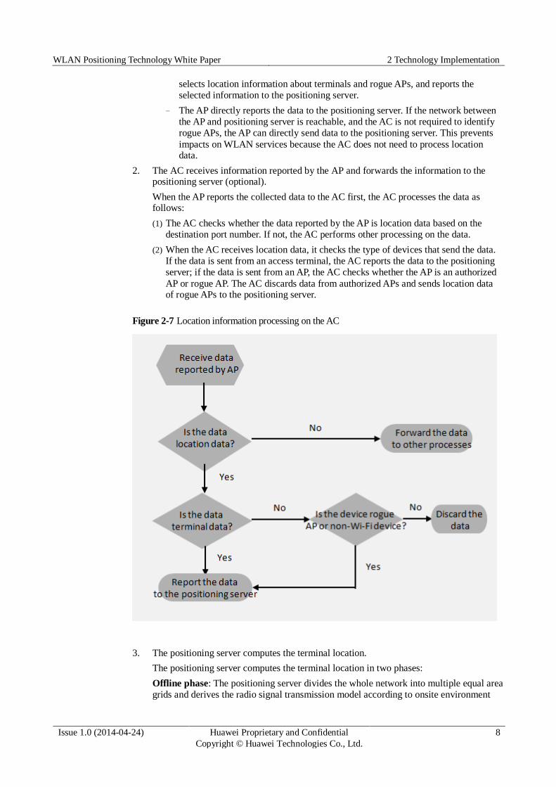
2. The AC receives information reported by the AP and forwards the information to the positioning server (optional).
When the AP reports the collected data to the AC first, the AC processes the data as follows:
(1) The AC checks whether the data reported by the AP is location data based on the
destination port number. If not, the AC performs other processing on the data.
(2) When the AC receives location data, it checks the type of devices that send the data.
If the data is sent from an access terminal, the AC reports the data to the positioning
server; if the data is sent from an AP, the AC checks whether the AP is an authorized
AP or rogue AP. The AC discards data from authorized APs and sends location data of rogue APs to the positioning server.
Figure 2-7 Location information processing on the AC
3. The positioning server computes the terminal location.
The positioning server computes the terminal location in two phases:
Offline phase: The positioning server divides the whole network into multiple equal area grids and derives the radio signal transmission model according to onsite environment

WLAN Positioning Technology White Paper 2 Technology Implementation
Issue 1.0 (2014-04-24) Huawei Proprietary and Confidential
Copyright © Huawei Technologies Co., Ltd.
9
characteristics (characteristics of indoor or outdoor environments and obstacles). In
combination with AP locations imported into the positioning server, the positioning
server computes the RSSI of a STA in a grid to each AP and stores the information in the database.
Online phase: APs report RSSIs to the positioning server after the APs (at least three
APs) receive location information of the terminal to be located. The positioning server
compares the RSSI information received by each AP with the information in the database to obtain the terminal location.
Figure 2-8 Location algorithm

WLAN Positioning Technology White Paper 3 Benefits to Customers
Issue 1.0 (2014-04-24) Huawei Proprietary and Confidential
Copyright © Huawei Technologies Co., Ltd.
10
3 Benefits to Customers
WLAN positioning technology brings considerable benefits to customers. Compared with
other positioning systems, WLAN positioning has low costs and applies to various scenarios.
It helps locate rogue APs and network faults in a timely manner, improving the O&M
efficiency. In addition, value-added applications based on WLAN positioning technology,
such as asset management and security monitoring provide enterprises with an increased level
of security assurance and improved efficiency. Precise advertisement push creates significant
business values. Huawei tag and terminal positioning solutions achieve a location accuracy of
3 to 5 meters at a movement speed lower than 3 km/hour.
1. Low deployment costs
WLAN has become one of the most popular hotspot access modes and widely used in
shopping malls, office buildings, restaurants, cafes, and parking lots. WLAN positioning
technology uses existing devices on a WLAN and requires no additional devices to offer
the location services, which reduces deployment and O&M costs.
2. Wide application scenarios
There are increased requirements on indoor applications of wireless positioning
technology, such as indoor navigation and asset location. Traditional positioning systems
such as GPS and cellular system are inapplicable to indoor scenarios because they
provide no signals or poor signals indoors. WLAN positioning applies to both indoor and
outdoor scenarios. Different from GPS or cellular system, the Wi-Fi system is widely
deployed and Wi-Fi signals are available indoors. This is also one important reason that most indoor positioning technologies are implemented based on the Wi-Fi system.
3. Improved O&M efficiency
WLAN positioning technology helps the O&M personnel accurately and quickly locate
interference sources in the system, such as rogue APs and non-Wi-Fi devices, improving network performance and reliability.
4. Rich value-added services
Rich value-added services are developed based on the WLAN positioning technology, which bring customers security, efficiency, and business values.
(1) Personnel tracking and locating: Fun parks and theme parks usually have complex
geographies and have a large number of entertainment facilities. Wireless positioning
technology helps locate lost children fast and accurately. Wireless positioning
technology helps monitor patients in hospitals or surveil prisoners in prisons and
alerts on escape of prisoners from supervision areas. In high-risk production
industries, such as the mining industry, wireless positioning technology is used to track miners and confirm the number, location, and status of workers.
WLAN Positioning Technology White Paper 3 Benefits to Customers
Issue 1.0 (2014-04-24) Huawei Proprietary and Confidential
Copyright © Huawei Technologies Co., Ltd.
11
(2) Device and asset management: The manufacturing and logistics industries use
wireless positioning technology to locate and manage key assets, monitor distribution
of production materials, track removal of goods, tools and devices to prevent them
against theft. Wireless positioning technology can help hospitals monitor and track
valuable medical equipment to protect them against theft and monitor device usage to improve device usage efficiency.
(3) Manufacturing visibility: In hospitals, wireless positioning is used to monitor the
medical treatment process, arrange medical consultation, and reduce congestion of
patients. The mining industry uses the wireless positioning system to monitor mineral
manufacturing, track trucks and other vehicles on or under the ground, prevent occurrence of collisions, and alert drivers about surrounding vehicles or personnel.
(4) Indoor navigation: The wireless positioning technology provides customers indoor
navigation services. Parking navigation helps a car driver find a parking place and
navigates the car there. Shopping navigation helps consumers find the desired shop in
a shopping mall. The navigation services bring great convenience to the users (consumers).
(5) Advertisement push: Shop vendors can use the wireless positioning technology to
push advertisements or sales promotion messages to consumers when the consumers
reach the shopping mall. The wireless positioning system notifies the consumers of the latest commodity information or discount offers to attract consumers.
(6) Business value analysis: The property owner can analyze historical location data and
record where users stay and how long they stay there to make consumer traffic
analysis. The property owner can charge for rental based on the consumer traffic analysis.

WLAN Positioning Technology White Paper 4 Typical Application Scenarios
Issue 1.0 (2014-04-24) Huawei Proprietary and Confidential
Copyright © Huawei Technologies Co., Ltd.
12
4 Typical Application Scenarios
WLAN positioning is widely applicable to many scenarios, including network fault
troubleshooting, location-based navigation, value-added service analysis based on historical
location data, as well as asset and personnel tracking.
1. Network fault troubleshooting
Wireless positioning is used to locate faults reported by users and interference sources in this scenario.
(1) Once a user reports a fault, the O&M personnel need to obtain the location where the
fault occurs to analyze surrounding environments and find the causes based on AP distribution, signal coverage, signal strength, and user access information.
(2) Many interference sources exist in the radio environment, such as rogue APs and
microwave ovens. These interference sources affect usage of WLAN. Even if the
network generates alarms about the interference sources, the O&M personnel still
cannot troubleshoot the fault if they do not obtain the positions of the interference sources.
Figure 4-1 Network fault troubleshooting
Microwave oven
The wireless positioning function provides and displays locations of terminals, rogue
devices, and interference sources, helping the O&M personnel troubleshoot network faults quickly.

WLAN Positioning Technology White Paper 4 Typical Application Scenarios
Issue 1.0 (2014-04-24) Huawei Proprietary and Confidential
Copyright © Huawei Technologies Co., Ltd.
13
To enable the wireless positioning function, perform the following configuration on the
WLAN (configurations on eSight are not provided here).
1. Run the system-view command to enter the system view.
2. Run the wlan command to enter the WLAN view.
3. Run the ap ap-id radio radio-id command to enter the AP's radio view.
4. Run the work-mode hybrid command to configure the AP radio to work in hybrid mode.
By default, the AP radio works in normal mode and only transmits data of wireless users.
5. Run the location enable command to enable terminal positioning on the AP.
By default, terminal positioning is disabled on an AP.
6. Run the channel scan-switch enable command to enable the AP to scan all channels.
By default, an AP scans only working channels.
If WIDS, spectrum analysis, background neighbor probing, or terminal positioning is configured on a radio, the radio cannot be used for WDS bridging or Mesh link setup.
7. Run the quit command to return to the WLAN view.
8. Run the radio-profile { id profile-id | name profile-name } * command to create a
radio profile and enter the radio profile view.
9. (Optional) Run the channel scan-time time command to configure the channel scan period.
The default period during which an AP scans channels is 60 ms.
This command applies to the WIDS, background neighbor probing, and terminal positioning functions.
10. (Optional) Run the channel scan-frequency time command to configure the channel scan interval.
The default interval at which an AP scans channels is 10s.
This command applies to the WIDS, background neighbor probing, and terminal
positioning functions.
11. (Optional) Run the location report-frequency time command to configure the interval at which an AP reports channel scan information.
By default, an AP reports channel scan information every 20s.
12. Run the quit command to return to the WLAN view.
13. Run the location ap report-server { ac | ip-address ip-addr } port port-num command to configure the destination IP address and port number for the AP to report
channel scan information.
By default, an AP reports channel scan information to the AC and uses the port
number 6411 to report the information.
14. Run the location ac report-server ip-address ip-addr port port-num command to
configure the destination IP address and port number for the AC to report channel scan information.
The destination IP address and port number used by the AC to report information are configured only when an AP is configured to report channel scan information to the AC.
15. Run the commit { all | ap ap-id } command to deliver the configuration to APs.
16. Run the display current-configuration command to view terminal positioning configurations.

WLAN Positioning Technology White Paper 4 Typical Application Scenarios
Issue 1.0 (2014-04-24) Huawei Proprietary and Confidential
Copyright © Huawei Technologies Co., Ltd.
14
2. Location-based navigation
Wireless positioning provides the following navigation services:
(1) In shopping malls, consumers can use the wireless positioning system to obtain
location information about surrounding shops and select their preferred shops for shopping.
(2) The shop vendors can push advertisements based on consumer locations.
(3) In scenic spots, tourists can use the wireless positioning system to obtain location information about surrounding tourist attractions and go to visit their preferred site.
(4) In large parking lots, car drivers can quickly find parking positions.
Figure 4-2 Location-based navigation
The wireless positioning system uses an API and third-party system to obtain user locations
and offer users navigation services based on the locations.
WLAN configuration in this scenario is similar to that in the first scenario.
3. Value-added service analysis based on user's historical locations
Value-added services that are developed based on historical location data include the following:
(1) The shopping mall analyzes the time duration when users stay in a shop based on historical location data, and offers users shopping guide based on the analysis results.
(2) The shopping mall can analyze consumer traffic of different shops based on the consumers' stay time in each shop and charges for rental based on the analysis.

WLAN Positioning Technology White Paper 4 Typical Application Scenarios
Issue 1.0 (2014-04-24) Huawei Proprietary and Confidential
Copyright © Huawei Technologies Co., Ltd.
15
Figure 4-3 Value-added service analysis
Movement traces in a specified time
The wireless positioning system can store users' historical location data and offer a third-party API to obtain historical movement traces of users for further analysis.
WLAN configuration in this scenario is similar to that in the first scenario.
4. Asset and personnel tracking
Healthcare, oil, gas, mining, and education industries need to monitor assets and
personnel to ensure their safety. Wireless positioning technology provides enterprises
with an increased level of security assurance and improved efficiency.
Figure 4-4 Asset and personnel tracking

WLAN Positioning Technology White Paper 4 Typical Application Scenarios
Issue 1.0 (2014-04-24) Huawei Proprietary and Confidential
Copyright © Huawei Technologies Co., Ltd.
16
This scenario uses tags produced by AeroScout or Ekahau. Configure the WLAN
network in the following way (in this example, AeroScout tags are used).
1. Run the system-view command to enter the system view.
2. Run the wlan command to enter the WLAN view.
3. Run the ap id ap-id command to enter the AP view.
4. Run the lbs aeroscout enable command to enable AeroScout tag positioning.
By default, AeroScout tag positioning is disabled.
5. Run the quit command to return to the WLAN view.
6. Runt the lbs aeroscout ap { to-ac | to-ae } port port-num command to configure the
destination IP address and port number used by the AP to report the received AeroScout tag information.
By default, the destination IP address and port number used by an AP to report tag information is not configured.
7. (Optional) Run the lbs aeroscout ae-port port-num command to configure the port
number used for communications between the AC and the AeroScout positioning
server. By default, the port number used by an AC to listen for messages sent from the AeroScout positioning server is not configured.
8. (Optional) Run the lbs source ip-addr ip-address command to configure the source
IP address of packets sent from the AC to the positioning server. By default, the
source IP address of packets sent from the AC to the positioning server is not configured.
If an AP is configured to report tag information to the AC, the port number used by the AC to
communicate with the AeroScout positioning server must be configured.
If an AP is configured to report tag information to the AC, the port number configured on the
AeroScout positioning server must be the same as that used by the AC to communicate with the server.
If an AP is configured to directly report tag information to the AeroScout positioning server, the port number used by the AP to report tag information must be the same as that configured on the server.
The port number used by the AP to report tag information must be different from that used by the AC to communicate with the positioning server.
If the positioning server runs the Linux system and is enabled with reverse route check, the positioning server must be able to ping the source IP address of the packets sent from the AC to the positioning server.
9. (Optional) Run the lbs aeroscout compound-time time-value command to configure
the aggregation time of AeroScout tag packets. The default aggregation time of AeroScout tag packets on an AC is 6553.5 seconds.
10. Run the commit { all | ap ap-id } command to deliver the configuration to APs.


![WLAN Fingerprinting based Indoor Positioning in the ... · [17] which normally require additional specialized hardware, the others use the radio signal strength information, i.e.,](https://static.documents.pub/doc/80x56/60e5a93446073b3ede7ce359/wlan-fingerprinting-based-indoor-positioning-in-the-17-which-normally-require.jpg)


