56
Wolf & Lamb Multicatalyst - Sequential One-Pot Reactions Roozbeh Yousefi January 9, 2008
Wolf & LambMulticatalyst - Sequential
One-Pot Reactions
Roozbeh Yousefi
January 9, 2008
Incompatibility
www.anime-cel.comwww.scardy-cat.com

Incompatibility
BaseAcid
www.greenair.com/techtips.htm

Synthesis of LYRICA (pregabalin)
Burk, M. J; Ramsden, J. A. J. Org. Chem. 2003, 68, 5731
O CN CNOH
CN
CO2Et
CN
CO2M
M= t-BuNH3
DABCO, H2O2,6-ditert-butyl-4-
methylphenol97%
ClCO2Et, pyridine
CH2Cl2, rtCN
OCO2Et
Pd(OAc)2, PPh3, EtOH
CO (300psi), 50 ˚C
1. LiOH, H2O, THF, rt; 2. HCl
3. tert-BuNH2 , EtOAc
Rh Catalyst H2 (45 psi)
MeOH, 55 ˚CCN
CO2M
99% 99.7%e.e.
1. Ni, KOH, H2 (50 psi)
H2O, EtOH; 2. AcOHCO2H
NH2 60%
83% 88%
95%
LyricaPain Relief
$ 465 M third quarter 2007P
PRh
BF4

0
20
40
60
80
100
120
2002 2003 2004 2005 2006
Organic waste Inorganic wasteHalogenated solvents Non-Halogenated solvents Hazardous packaging Others
Hazardous Operational Waste in Pharmaceutical & Chemical Industry
(KT)
Year
www.corporatecitizenship.novartis.com
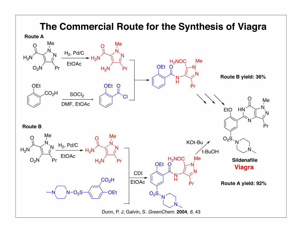
Viagra
Dunn, P. J; Galvin, S. GreenChem. 2004, 6, 43
The Commercial Route for the Synthesis of Viagra
OEt
O2S NN
O
NH
NN
Me
Pr
H2NOCt-BuOH
H2, Pd/C NN
O Me
PrH2N
H2NEtOAc
EtO
O2S NN
N
HN NN
O Me
Pr
Sildenafile
CDIEtOAc
CO2HOEt
SOCl2DMF, EtOAc
OEt
Cl
O
H2, Pd/C NN
O Me
PrH2N
H2NEtOAc
NN
O Me
PrO2N
H2N
NN
O Me
PrO2N
H2N
OEt O
NH
NN
Me
Pr
H2NOC
Route A
Route B
Route A yield: 92%
Route B yield: 36%
O2SNN OEt
CO2H
KOt-Bu

soluble in all proportions and is difficult to recover for reuse. There
is a continued drive for improved environmental performance and
t-butanol will be switched to another reaction solvent that can be
recovered. This new process was developed and optimised in
Ringaskiddy and has been demonstrated in the production plant in
Ireland. When fully implemented this will give the final optimised
solvent usage of 4 L Kg21.
A more detailed environmental analysis of the optimised
medicinal chemistry synthesis (1994), the 1997 commercial route
and the future target follows, using such measures as atom
economy, reaction mass efficiency, chemical yield, organic waste,
aqueous waste, atmospheric emissions, energy usage and the E-
factor. The original medicinal chemistry process (1990) is not
analysed here, since it was only ever intended for laboratory scale
synthesis.
Atom economy, reaction mass efficiency and
chemical yield
The concept of atom economy was first introduced by Barry Trost7
as a prompt to synthetic chemists to pursue “greener chemistry”.
The method of calculating atom economy was kept deliberately
simple and is a percentage of how much of the reactants remain in
the final product. Hence, atom economy ignores reaction yield and
reagent excess. It also does not account for solvent usage. Further
information on how to calculate atom economy can be found in
Green Chemistry.3
Reaction Mass Efficiency (RME)2,3 is a more sophisticated
measure of “greenness” which allows for the effect of yield and the
excesses of reagent used. RME does not account for solvent
usage.
For a generic reaction A + B = C
The atom economy, reaction mass efficiency and chemical yields
for the sildenafil citrate processes in 1994 (optimised medicinal
chemistry route), 1997 (commercial route) and the future target
(commercial route) are shown in Tables 2 to 4.
As can be seen from the data, the atom economy of the process
has remained essentially constant over time. Improvements have
been made in yield and through a greater degree of convergency in
the synthesis, but these are not measured by atom economy. In
contrast, there was a substantial improvement in both RME and
chemical yield between 1994 and 1997 when the new route was
introduced. There has been a further significant incremental
improvement since 1997. A summary of the data in Tables 2–4 is
given in Fig. 2.
Fig. 1 The amount of organic waste produced by the sildenafil citrate processes at various time points.
Table 2 Optimised medicinal chemistry process 1994
Reaction type Step No RME Atom econ. Yield
Amide formation 1 25% 61% 92%Reduction (nitro to amine) 2a 83% 83% 100%Activation/acylation 2b 48% 71% 84% from (2)Cyclisation 3 61% 65% 100%Chlorosulfonation/sulfonamide formation 4 Reaction 73% 90% 71%
4 Purification 80% 100% 80%Salt formation 5 Reaction 91% 100% 91%
5 Purification 90% 100% 90%Overall process 10%8 56% 36% from (1)
Table 3 Commercial process (1997)
Reaction typeStepnumber RME
Atomecon. Yield
Amide formation 1 40% 61% 92%Chlorosulfonation/sulfonamide
formation 2 30% 74% 68%Reduction (nitro to amine) 3a 83% 83% 100%Activation/acylation 3b 61% 73% 90% from (2)Cyclisation 4 65% 83% 92%Salt formation 5 98% 100% 99%Overall process 26%8 54% 75% from (1)
G r e e n C h e m . , 2 0 0 4 , 6 , 4 3 – 4 84 6
1300 L/KgMedicinal Chemistry
1990
100 L/KgOptimized
Med. Chemistry
22 L/KgCommercial Route 1997
7 L/KgCommercial
Route following solvent recovery
4 L/KgFuture Target
DCMAcetoneEthanol
MethanolEther
Ethyl Acetate
Toluene2-Butanone
Pyridinet-Butanol
New solvent
The Amount of Solvent Waste Produced in Different Route
Dunn, P. J; Galvin, S. greenChem. 2004, 6, 43

Cat 1
Cat 2
Cat 3 Cat 4
A
BC
D
E
FProduct
A
B C
D
Cat 1Cat 2
Cat 3
Multicatalyst Sequential Reactions are the Solution
1. Flow process synthesis
2. One pot multicatalyst synthesis

Baxendale, I. R.; Ley, S. V. Chem. Commun. 2006, 2566
A Flow Process Synthesis of Oxomaritidin
OMeMeO
OH
OMeMeO
O
H
HO
N3
HO
Br
HO
OMeMeO
N
HO
OMeMeO
NH
20 equiv., 70 ˚CCH3CN,THF (1:1)
50µL/min
10 equiv., r.t. THF50µL/min
Flow Hydrogenation
10% Pd/C THF
20 equiv., 1) rt, 2) 55˚C
solvent change to dichloromethane
PhP(n-Bu)2
NMe3RuO4
NMe3N3

PIFA
HO
OMeMeO
NH
CH2Cl2
35µl/min
HO
OMeMeO
N
O CF3
80˚C
chipCF3
O
O
O
F3C
N
O
MeO
MeOCF3
O
N
O
MeO
MeOH
MeOH, H2O 4:170µL/min
Baxendale, I. R.; Ley, S. V. Chem. Commun. 2006, 2566
PIFA: (ditrifluoroacetoxyiodo)benzene
90% Purity
NMe3OH

Cat 1
Cat 2
Cat 3 Cat 4
A
BC
D
E
FProduct
A
B C
D
Cat 1Cat 2
Cat 3
1. Flow process synthesis
2. One pot multicatalyst synthesis
Multicatalyst Sequential Reactions are the Solution
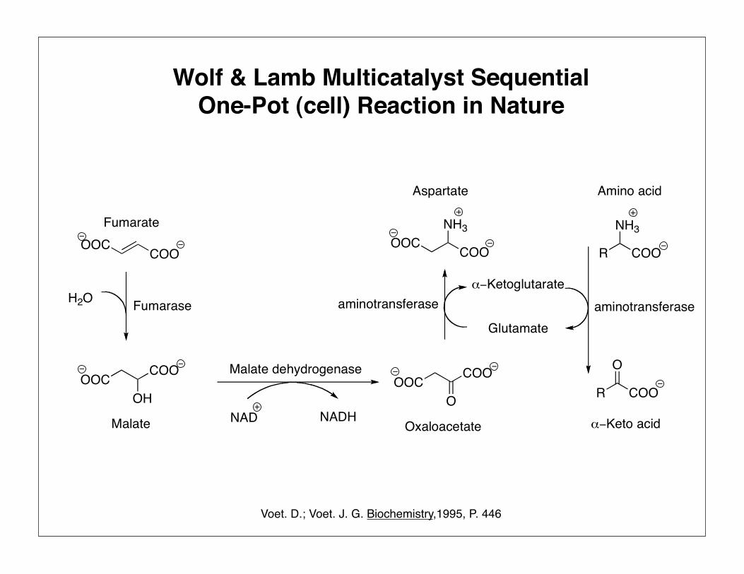
Wolf & Lamb Multicatalyst SequentialOne-Pot (cell) Reaction in Nature
Voet. D.; Voet. J. G. Biochemistry,1995, P. 446
OOC COO
Fumarate
H2O Fumarase
OOC COO
OH
Malate
Malate dehydrogenase
NAD NADH
OOC COO
O
aminotransferaseα−Ketoglutarate
Glutamate
R
O
COO
R COO
NH3OOC COO
NH3
aminotransferase
Amino acid
α−Keto acid
Aspartate
Oxaloacetate

Selectivity & Site Isolation in Nature
Substrates ProductIntermediate A Intermediate B

Wolf & Lamb Reactions
Cohen, B. J. J. Am. Chem. Soc. 1981, 103, 7620
B
B
A no reaction
S SA
SA SAB
A
S
AB
S + A SA SAB desired productB
Undesired ProductWolf: A Lamb: B

Acylation of a Carbon Acid
Cohen, B. J. J. Am. Chem. Soc. 1981, 103, 7620
C
NO2
O
PhO
CNPh
OPh
CNPhPh CN
HCNPh CNPh
OPhPh CN
Desired Product
Ph O
O
PhCN
Ph
Undesired Product
45%
THF THF
NO2
O
PhO

Acylation of Carbon Acid: Wolf & Lamb Approach
Cohen, B. J. J. Am. Chem. Soc. 1981, 103, 7620www.lpb.org/kids
C
NO2
O
PhO
CNPh
OPh
Ph CN
H
CNPh
P P
CHNHPh
OPh
5 equiv. 2 equiv.1 equiv
94%THF THF

Cohen, B. J. J. Am. Chem. Soc. 1981, 103, 7620
Ph CNO O
O
NO2
Ph CN
OO
Starting materialAcylating reagent Product
Wolf & lambYield %
Yield %reaction in solution
91% 37%
H3C CN
Ph
O
O
N
Ph
O O O
O
NO2
O Ph
O
NO2
O Ph
O
NO2
O Ph
O
NO2
O
O
Ph
OO
O
Ph
O
N
Ph
O
Ph
O
NC 90%
96%
92%
92%
27%
48%
40%
42%
Ph

Cat 1
Cat 2
Cat 3 Cat 4
A
BC
D
E
FProduct
A
B C
D
Cat 1Cat 2
Cat 3
1. Flow process synthesis
2. One pot multicatalyst synthesis
Multicatalyst Sequential Reactions are the Solution

Wolf & Lamb Catalyst Immobilization
2. Solid polymeric acid and base
3. Layered Clay Acid and Base
1. Polyurea Microcapsules
2. Star polymer capsule
3. Polymersome
Immobilization on Solid support
Immobilization in Microcapsule
1. Solid polymeric acid and nanoparticle base

Site Isolated & Recoverable Catalyst
OO Si
OHNH
NH2
SO3H
CoFe2O4
PolymerResin Pt / Al2O3
Super paramagnetic spinel ferrite nanoparticle functionalized with base
Sulfonic acid polymer resin (amberlyst A15)
Gill, C. S.; Jones, W. C. Angew. Chem. Int. Ed. 2007, 45, 2209

Tandem Deacetalization- Knoevenagel & Hydrogenation
Pt/Al2O3 catalyst
H2
NC
CN
CN
CNbase catalyst
CH2(CN)2
catalyst conv [%]first step
conv [%]second step
solid acid, solid base
solid acid
solid base
solid acid, liquid base
solid base, liquid acid
100
100
0
0
0
100
0
0
0
0
conv [%]third step
100
0
0
0
0
Gill, C. S.; Jones, W. C. Angew. Chem. Int. Ed. 2007, 45, 2209
O
O
O
Hacid catalyst
H2O (1 equiv.)Solvent: Toluene

Wolf & Lamb Catalyst Immobilization
2. Solid polymeric acid and base
3. Layered Clay Acid and Base
1. Polyurea Microcapsule
2. Star polymer capsule
3. Polymersome
Immobilization on Solid support
Immobilization in Microcapsules
1. Solid polymeric acid and nanoparticle base

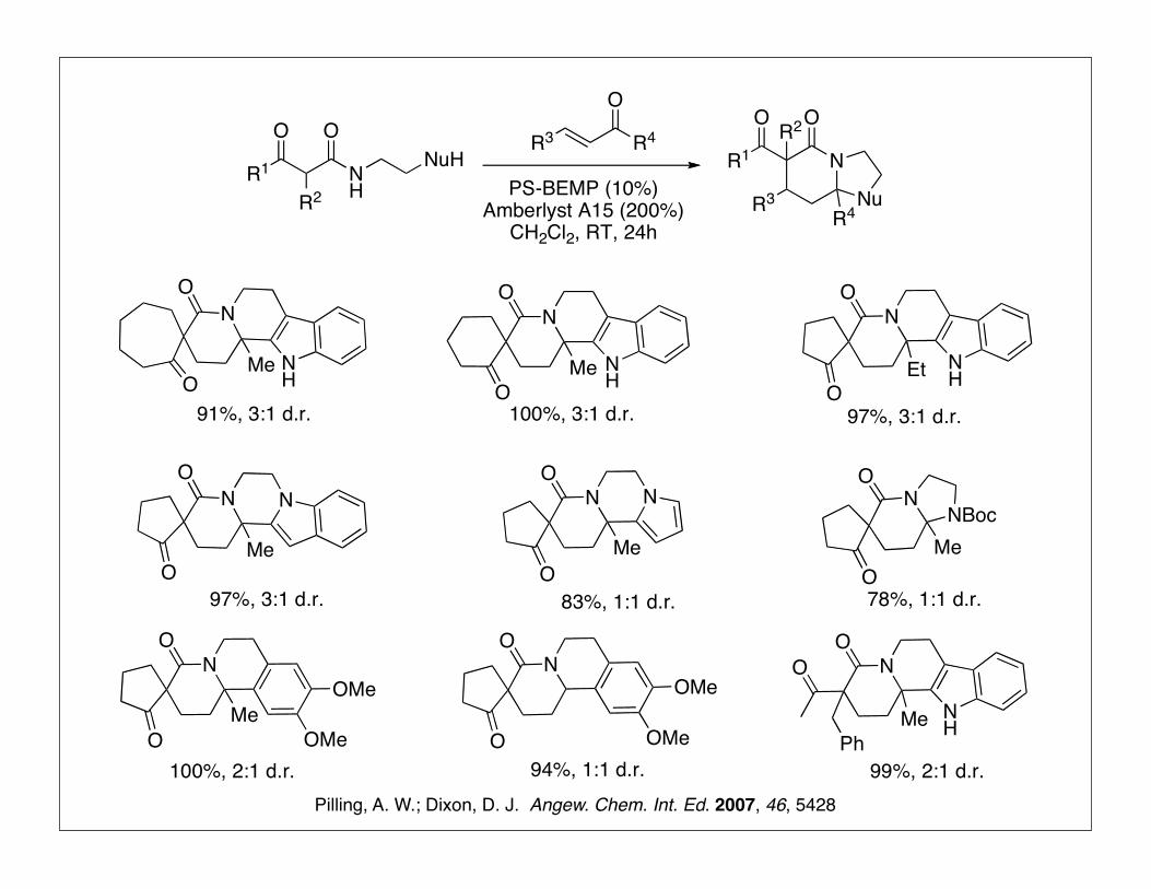
One-Pot Complex Heterocycle Synthesis
Pilling, A. W.; Dixon, D. J. Angew. Chem. Int. Ed. 2007, 46, 5428
NR2R1
O
R3 R4 Nu
NH
O
H
R2R1
HNu
base-catalyzedMichael addition
NR2
R1
O
R3 NuR4
H
Nu
NH
R2
R1
O
R3 NuH
Nu
R4O
acid-catalyzedN-acyl iminiumion formation
-H2O
Nucleophilicring closure
O
R4R3
O
R4R3
One-Pot site-Isolated base and acid Catalysis?

One-Pot Complex Heterocycle Synthesis
Pilling, A. W.; Dixon, D. J. Angew. Chem. Int. Ed. 2007, 46, 5428
O O
NH
NO
Me
N N
Me
O
O
PS-BEMP (10%)Amberlyst A15 (200%)CH2Cl2, RT, 24hO
NH
N
O
Me
O
Ps-BEMP (10%)CH2Cl2, RT, 2h
Acid and Base
Acid
Base
O
NH
ON O
Me
O
Me
Amberlyst A15 (200%) CH2Cl2, RT, 36h
Base Acid
Amberlyst A15
SO3H
83%
N NPNt-BuEt2N
PS-BEMP

Base Mediated Catalytic Cycle
SO3H
Amberlyst A15
N
ON
N
O
Product
Amberlyst A15N-acyl iminiumion formation
Nucleophilicring closure
O
O
N
N NPNHt-BuEt2NO
NH
ON
O
NH
ON
O
NH
ON
O
N NPNt-BuEt2N
N NPNHt-BuEt2N
pKa: 16.2
O
PS-BEMP
O
NH
O
O
N
NH
NO
O
Ph
NH
NO
ONH
NO
OEtN
H
NO
MeO
Me
Me
NNO
OMe
OMe
OMe
N
O
O
MeOMe
OMe
N
O
O
NNO
OMe
NO
OMe
NBoc
R1
O
R2NH
ONuH
R3 R4
O
N
Nu
O
R4R3
O
R1R2
PS-BEMP (10%)Amberlyst A15 (200%)
CH2Cl2, RT, 24h
91%, 3:1 d.r. 100%, 3:1 d.r. 97%, 3:1 d.r.
78%, 1:1 d.r.83%, 1:1 d.r.97%, 3:1 d.r.
100%, 2:1 d.r. 94%, 1:1 d.r. 99%, 2:1 d.r.Pilling, A. W.; Dixon, D. J. Angew. Chem. Int. Ed. 2007, 46, 5428

Wolf & Lamb Catalyst Immobilization
2. Solid polymeric acid and base
3. Layered Clay Acid and Base
1. Polyurea Microcapsule
2. Star polymer capsule
3. Polymersome
Immobilization on Solid support
Immobilization in Microcapsules
1. Solid polymeric acid and nanoparticle base

Combination of Acidic & Basic Layered Clay
Ti+4--
- -Ti+4--
- -Ti+4--
- -Ti+4--
- -Ti+4--
- -Ti+4--
- -
Ti+4--
- -Ti+4--
- -Ti+4--
- -
• Hydrotalcites are layered, mixed hydroxides of Mg and Al which can act as solid base catalysts
• Ti+4-mont acts as strong acid associated with the chain-like Ti domains within the interlayer.
• In organic solvents, the interlayer space is effectively expanded, allowing access of the substrates to the catalytic site of the Ti species.
Hydrotalcite (HT)
Ti+4 -exchanged montmorillonite
Motokura, K.; Kaneda, K. J. Am. Chem. Soc. 2005, 127, 9674.
Pd/HT
OH OH OH OHOHOH
OH OH OH OHOHOH
OH OH OH OHOHOH
Pd
Pd
Pd
Pd
Pd
Pd
PdPd
PdPd
OH OH OH OHOHOH
OH OH OH OHOHOH
OH OH OH OHOHOH

The Longest Sequential Multicatalyst Reactions
Ph COOMe
CN
CNCNPh
CN
COOMe
88%
Ph COOMe
CN
H2
Ph COOMe
CN
Ph COOMe
CN
O
91%
H2O2
O
O
Ti+4 - mont, Pd/HTHTNC COOH
MeOHNC COOMe
Ti+4 - mont, HTPd/HTTi+4 - mont,
benzaldehyde
Motokura, K.; Kaneda, K. J. Am. Chem. Soc. 2005, 127, 9674.

2. Solid polymeric acid and base
3. Layered Clay Acid and Base
1. Polyurea Microcapsule
2. Star polymer capsule
3. Polymersome
Immobilization on Solid support
Immobilization in Microcapsules
1. Solid polymeric acid and nanoparticle base
Wolf & Lamb Catalyst Immobilization

Enantioselective Michael Addition of 1,3 Dicarbonyl to Conjugated Nitroalkenes
D. A. Evans.; D. Seidel. J. Am. Chem. Soc. 2005, 127, 9985
R H
O
R
OHNO2
NO2R10M NaOH,
0˚C, EtOH
(CF3CO)2O, Et3N
CH2Cl2, 0˚C to RT
NHNi
NH
HN
HNBr
Br
2 mol%toluene, 4h, RT
Bn
Bn
Bn
Bn
NO2Ph
OO
MeO OMe1.2 equiv
MeO
O
CO2Me
PhNO2(S)
CH3NO2
EtO
O
CO2Me
NO2 MeO
O
CO2Me
PhNO2 BnO
O
CO2Me
PhNO2
yield(%): 94 ee(%): 88 yield(%): 99 ee(%): 95yield(%): 99 ee(%): 94

NNi
NOO
OMe
OMe
Bn
Bn H
H Br
NHPh
H
O2N HBnNH.HBr
Enantioselective Michael Addition of 1,3 Dicarbonyl to Conjugated Nitroalkenes
D. A. Evans.; D. Seidel. J. Am. Chem. Soc. 2005, 127, 9985

Is it Possible to Mix two Catalysts Together?
HO
NO2 Cat 1
CH3NO2
Cat 1
CH3NO2
NO2
NO2
Cat 2DMM
O
O
O
O
NO2
NH
N
NH2
x y
Cat 1
HN
NiNH
HN
NH
Bn
Bn
Bn
BnBr
Br
Cat 2
Cat 1
Cat 2
DMM
CH3NO2

Poe, S. L.; McQuade, D. T. J. Am. Chem. Soc. 2006, 128, 15586
Wolf & Lamb Catalyst
S7
5.2. Qualitative assessment of nickel catalyst interaction with µcaps and free PEI
To nickel catalyst (2, 60 mg) dissolved in toluene (1 mL), either µcap catalyst (1, 30 mg) or,
as a control, free PEI (30 mg) was added. Color change was captured with a digital camera and
displayed below.
Figure S5. Qualitative assessment of nickel catalyst interaction with µcaps and free PEI: µcaps,
two solutions of nickel catalyst, and free PEI (A), µcaps being added to the nickel catalyst
solution (B), free PEI being added to the nickel catalyst solution (C), and comparison of nickel
catalyst solutions with µcaps and free PEI added (D).
5.3. Michael addition in the presence and absence of microencapsulated PEI (1)
The Michael addition between trans-!-nitrostyrene (4) and dimethyl malonate was performed
in the presence and absence of microencapsulated PEI (1) in order to determine if the presence
of the µcaps decreases the catalytic activity of the nickel catalyst (2). In order to prevent the
binding of trans-!-nitrostyrene to the µcaps (described in Supporting Information section 4),
the primary amines of the µcaps were acylated with acetic anhydride (acylation with acetic
anhydride was done in the same manner as with trifluoroacetic anhydride described in the
section 2.2 Catalyst Loading above). The Michael additions were performed as followed: to
either a vial containing 30 mg acylated µcaps swollen in 0.5 mL MeOH, a vial containing 30
mg of untreated µcaps swollen in 0.5 mL MeOH, or a vial containing 0.5 mL MeOH was
added trans-!-nitrostyrene (4) (149.2 mg, 1 mmol), nickel catalyst 2 (16.2 mg, 2.0 mol%), and
toluene (1 mL). The vial was sealed with a screw cap and he reaction was rocked at room
temperature on a rocker. Reaction conversion was monitored by withdrawing aliquots from
Wolf
Wolf Lamb
Lamb
HN
NiNH
HN
NH
Bn
Bn
Bn
BnBr
Br
Encapsulation
ActiveDual Catalyst
SystemNH
N
NH2
x y
NH
N
NH2
x yHN
NiNH
HN
NH
Bn
Bn
Bn
BnBr
BrInactive
Dual Catalyst System
Racemic

Microcapsule Enabled Multicatalyst System
Poe, S. L.; McQuade, D. T. J. Am. Chem. Soc. 2006, 128, 15586
Ph H
O OO
MeO OMe MeO
ONO2CH3NO2
Ph
O OMe
1 (6.9%)2 (7.4%)
PhMeMeOH
80.2%
Conversion of Benzaldehyde: 95%
21
HN
NiNH
HN
NH
Bn
Bn
Bn
BnBr
Br activeDual Catalyst
SystemNH
N
NH2
x y
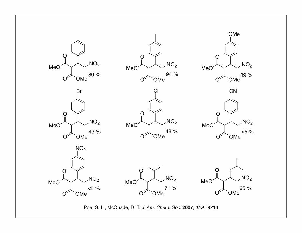
MeO
ONO2
O OMe
MeO
ONO2
O OMe
MeO
ONO2
O OMe
MeO
ONO2
O OMe
MeO
ONO2
O OMe
MeO
ONO2
O OMe
MeO
ONO2
O OMe
MeO
ONO2
O OMe
MeO
ONO2
O OMe
OMe
Br Cl CN
NO2
80 % 94 % 89 %
43 % 48 %
<5 %
<5 %
71 % 65 %
Poe, S. L.; McQuade, D. T. J. Am. Chem. Soc. 2007, 129, 9216

Synthesis of LYRICA (pregabalin)
Burk, M. J; Ramsden, J. A. J. Org. Chem. 2003, 68, 5731
O CN CNOH
CN
CO2Et
CN
CO2M
M= t-BuNH3
DABCO, H2O2,6-ditert-butyl-4-
methylphenol97%
ClCO2Et, pyridine
CH2Cl2, rtCN
OCO2Et
Pd(OAc)2, PPh3, EtOH
CO (300psi), 50 ˚C
1. LiOH, H2O, THF, rt; 2. HCl
3. tert-BuNH2 , EtOAc
Rh Catalyst H2 (45 psi)
MeOH, 55 ˚CCN
CO2M
99% 99.7%e.e.
1. Ni, KOH, H2 (50 psi)
H2O, EtOH; 2. AcOHCO2H
NH2 60%
83% 88%
95%
LyricaPain Relief
$ 465 M third quarter 2007P
PRh
BF4
Poe, S. L.; McQuade, D. T. J. Am. Chem. Soc. 2007, 129, 9216
HN
NiNH
HN
NH
Bn
Bn
Bn
BnBr
Br
NH
N
NH2
x y
Cat 1 Cat 2
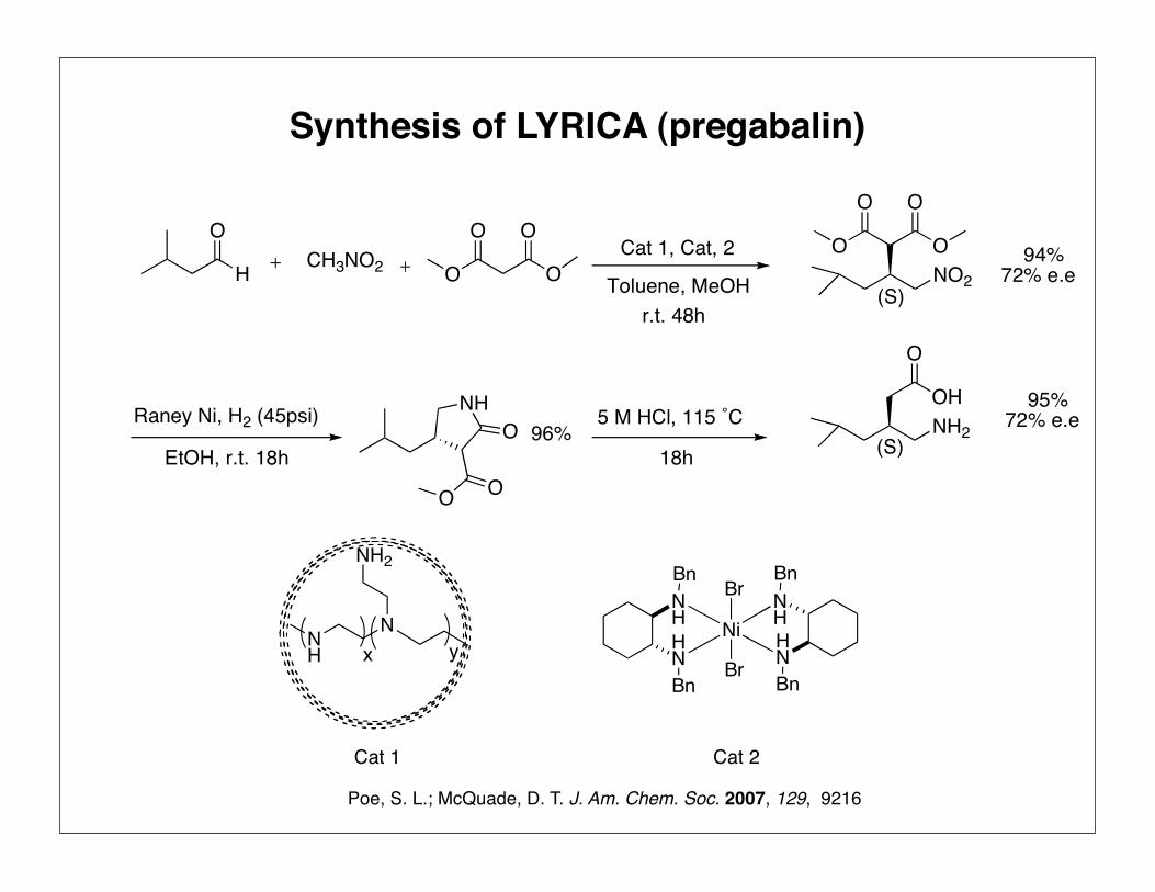
Synthesis of LYRICA (pregabalin)
H
OCH3NO2 O
O O
O Toluene, MeOHr.t. 48h
O
O O
ONO2
(S)
Raney Ni, H2 (45psi)
EtOH, r.t. 18h
NH
O O
O 5 M HCl, 115 ˚C
18h
O
OHNH2
(S)
94%72% e.e
95%72% e.e96%
Cat 1, Cat, 2

NN
N
NN
NH2 NH2 NH2
Micro-Encapsulation through Oil in OilInterfacial Polymerization
NCO
NCO
Kobaslija, M.; McQuade, D. T. Macromolecules. 2006, 39, 6371
DMF, Methanol
cyclohexane
HN
O N
NH
O N
HN
O
NH
O N
NN
N
NN
cyclohexane

Wolf & Lamb Catalyst Immobilization
2. Solid polymeric acid and base
3. Layered Clay Acid and Base
1. Polyurea Microcapsule
2. Star polymer capsule
3. Polymersome
Immobilization on Solid support
Immobilization in Microcapsules
1. Solid polymeric acid and nanoparticle base

Star Polymers
this strategy. In contrast, recent reports from a number of
groups10 have detailed the application of nitroxide11 or ATRP12
living radical polymerizations to the synthesis of star polymers,
which overcomes many of these limitations. While a number
of approaches are possible, the most promising involves the
coupling of preformed linear chains, containing a dormant chain
end, with a cross-linkable monomer such as divinylbenzene.
Traditionally, such an approach has been complicated by the
large number of reaction and structure variables that limits the
ability to optimize and control the structure of the resulting star
polymers. This deficiency has recently been overcome by
employing high-throughput “combinatorial” techniques for the
rapid screening and optimization of these multivariable systems
and has permitted the synthesis of well-defined three-dimen-
sional star polymers by living free radical techniques.13
In this report, we describe the development of a modular
approach for the preparation of functionalized star polymers,
which permits the custom synthesis of a wide variety of
functionalized materials. As shown in Figure 1, the applicability
of living free radical procedures to the preparation of function-
alized block and random copolymers from hydrophilic, hydro-
phobic, or fluorinated segments, potentially containing acidic,
basic, or H-bonding groups, enables the production of libraries
of linear polymers incorporating combinations of these features.
While this structural diversity is important, a critical feature of
our approach is the incorporation of a dormant initiating group
at one of the chain ends of these linear polymers.14 Activation
of these chain ends, followed by their coupling under conditions
optimized for star polymer formation, then leads to a myriad
of functionalized three-dimensional star polymers with accurate
control over molecular weight, arm length, and both the nature
and the placement of functional groups. These unique structures
are useful in a range of applications as supramolecular hosts,
catalytic scaffolds, or substrates for nanoparticle formation.
Experimental Section
General Methods. DMF, technical grade DVB (55% m- and
p-divinylbenzene, with the remainder consisting mostly m- and p-
ethylstyrene), all monomers, and reagents were used as obtained
(Aldrich), except for 2- and 4-vinylpyridine, which were purified over
alumina. Toluene and THF were distilled from sodium under a nitrogen
atmosphere. The CDCl3 employed in the hydrogen-bonding experiments
was dried by passing over alumina before use. Nitroxide 1 and
alkoxyamines 2 and 3 were prepared as described by Hawker et al.15,16
The L-Tyr-based ligand 4,17 dendritic initiator 5,18 and 2,6-bis-
(acetylamino)pyridine 619 were synthesized according to literature
(9) (a) Tsoukatos, T.; Hadjichristidis, N. J. Polym. Sci., Part A: Polym. Chem.2002, 40, 2575. (b) Al-Muallem, H. A.; Knauss, D. M. J. Polym. Sci.,Polym. Chem. 2001, 39, 3547. (c) Hull, D. L.; Kennedy, J. P. J. Polym.Sci., Polym. Chem. 2001, 39, 1525. (d) Moschogianni, P.; Pispas, S.;Hadjichristidis, N. J. Polym. Sci., Polym. Chem. 2001, 39, 650.
(10) (a) Narrainen, A. P.; Pascual, S.; Haddleton, D. M. J. Polym. Sci., Polym.Chem. 2002, 40, 439. (b) Stenzel-Rosenbaum, M.; Davis, T. P.; Chen, V.;Fane, A. G. J. Polym. Sci., Polym. Chem. 2001, 39, 2777. (c) Quinn, J. F.;Chaplin, R. P.; Davis, T. P. J. Polym. Sci., Polym. Chem. 2002, 40, 2956.
(11) (a) Tsoukatos, T.; Pispas, S.; Hadjichristidis, N. J. Polym. Sci., Polym. Chem.2001, 39, 320. (b) Pasquale, A. J.; Long, T. E. J. Polym. Sci., Polym. Chem.2001, 39, 216. (c) Hawker, C. J. Angew Chem., Int. Ed. Engl. 1995, 34,1456.
(12) (a) Baek, K. Y.; Kamigaito, M.; Sawamoto, M. J. Polym. Sci., Polym. Chem.2002, 40, 1972. (b) Baek, K. Y.; Kamigaito, M.; Sawamoto, M. J. Polym.Sci., Polym. Chem. 2002, 40, 2245. (c) Baek, K. Y.; Kamigaito, M.;Sawamoto, M. J. Polym. Sci., Polym. Chem. 2002, 40, 633. (d) Zhang, X.;Xia, J. H.; Matyjaszewski, K. Macromolecules 2000, 33, 2340.
(13) Bosman, A. W.; Heumann, A.; Klaerner, G.; Frechet, J. M. J.; Hawker, C.J. J. Am. Chem. Soc. 2001, 123, 6461.
(14) (a) Burguiere, C.; Dourges, M. A.; Charleux, B.; Varion, J. P. Macromol-ecules 1999, 32, 3883-3890. (b) Hawker, C. J.; Hedrick, J. L. Macro-molecules 1995, 28, 2993. (c) Hawker, C. J. J. Am. Chem. Soc. 1994, 116,11185.
(15) Dao, J.; Benoit, D.; Hawker, C. J. J. Polym. Sci., Part A: Polym. Chem.1998, 36, 2161-67.
Figure 1. Schematic representation of the modular approach to star polymers.
A R T I C L E S Bosman et al.
716 J. AM. CHEM. SOC. 9 VOL. 125, NO. 3, 2003
Bosman, A. W; Frechet, J. M. J. J. Am. Chem. Soc. 2003, 125, 715
Library 1: Library 2: Library 3:
Solubility End groupFunctionality
Acidic
Basic
H-Bonding
Synthon
Ligand
Hydrophobic
Fluorinated
Hydrophilic
Set of stars:

Star Polymer Acid & Base Synthesis
S OHOO
N
N
Helms, B.; Frechet, J. M. J. Angew. Chem. Int. Ed. 2007, 44, 6384
O N
n
Styrene, DMF
125˚C
O
NN
NHO
1 4 10
O N
n
S OOO
1. Styrene, DMF 125˚C
2. KOH
1 4 10
3. H

Star Polymer Wolf & Lamb Catalyst
Acid Base
Acid Base+
Acid Base
Salt
Helms, B.; Frechet, J. M. J. Angew. Chem. Int. Ed. 2007, 44, 6384

One Pot Cascade Reaction(Acetal Hydrolysis & Baylis Hillman)
Entry Acid Catalyst Base Catalyst Deprotection Yield [%]
Baylis Hillman Yield [%]
1
2
3
4
5
6
star polymer
star polymer
PTSA
PTSA
star polymer
linear polymer
star polymer
DMAP
star polymer
DMAP
linear polymer
star polymer
34
9
6
3
<1
<1
65
0
0
0
0
0
Helms, B.; Frechet, J. M. J. Angew. Chem. Int. Ed. 2007, 44, 6384
MeO OMeH
O2N
H
O
O2N O2N
OOHacid Cat.10 mol %
DMF, H2O
amine Cat.10 mol %
O

S OHOO
N
N
nNHOArm:Arm:
n
Star Polymer Wolf & Lamb Catalyst
MeO OMeH
O2N
H
O
O2N O2N
OOHacid Cat.10 mol %
DMF, H2O
amine Cat.10 mol %
O

Wolf & Lamb Catalyst Immobilization
2. Solid polymeric acid and base
3. Layered Clay Acid and Base
1. Polyurea Microcapsule
2. Star polymer capsule
3. Polymersome
Immobilization on Solid support
Immobilization in Microcapsules
1. Solid polymeric acid and nanoparticle base

Liposome and Its Structure
Protein Channel
Bilayer lipid
Inside cell
Outside cell
Protein Molecule
Carbohydratechain
Protein Molecule
http://www.bioteach.ubc.ca/Bio-industry/Inexhttp://library.thinkquest.org
LiposomeCell Membrane

Liposome & Its Application
Vitamin E
Vitamin C
Drug
http://www.nanopharmaceuticals.org

Block Copolymers & Polymersomes
O OH
N3150 20
Polymerosome:1. More tunable because of unlimited variety in block copolymer and polymerization method.
2. Less dynamic because of the larger dimension of the amphiphilic block copolymers
3. Diffusion is slower as a result of thicker shell
Block copolymers: 1. Comprised of two or more homopolymer subunits linked by covalent bonds.
2. They have the same architecture as lipids, in that they possess a hydrophilic head group and hydrophobic tail.
Discher, D. E; Eisenberg, A. Science, 2002, 297, 967

aggregates. However, no polymerization occurred and onlysmaller vesicles were formed, which contained entrappedmetal complexes. TEM studies on these samples revealed thatthere was a high concentration of FeCl3 located near or in themembrane of the vesicles (inset II in Figure 2a).
The aggregation behavior of PS-PIAT was subsequentlystudied in water by injecting a PS-PIAT solution in THF(0.5 gL!1) into ultra-pure water, which gave a final water/THF ratio of 5:1 (v/v).[9] After the solution was allowed toequilibrate over two days, the morphology of the aggregateswas examined by cryogenic scanning-electron microscopy(cryo-SEM) and SEM (Figure 2c). In both the SEM and cryo-
SEM images spherical particles were visible.A number of these particles contained holes,which shows that they had a hollow interior.From this evidence, it was concluded that theaggregates were vesicular in nature. Inclusionexperiments with the water-soluble fluores-cence probe ethidium bromide, followed bysize-exclusion chromatography, also indicat-ed that the spherical particles were vesi-cles.[10] Fluorescence microscopy studies ofthese filled vesicles and of vesicles filled withmethylene blue support the vesicular natureof the spheres. Their membranes had athickness of 30" 10 nm (see bottom-left insetin Figure 2c), which corresponds to twice thelength of a single PS-PIAT molecule. The
most likely membrane structure of the vesicles in water istherefore a bilayer of PS-PIAT molecules in which thepolystyrene blocks are pointed towards the center of themembrane and the polyisocyanide blocks towards the solvent(Figure 2d).[2]
The SEM images revealed that upon drying the formedPS-PIAT vesicles retained their shape. These vesicles havetherefore a much higher stability than the vesicles formed inCHCl3, which arises from the different constitutions of theirvesicle membranes. In pure water, or when only a smallamount of organic solvent is present, the polystyrene blocksare in their glassy state, and consequently, there is noreorganization after evaporation of the solvent water, so thevesicles preserve their shape. In CHCl3 the polystyrene blocksare in direct contact with the solvent, which gives them a highdegree of flexibility, allowing the vesicles to collapse when theCHCl3 evaporates.
The vesicles in THF/water (1:5 v/v) were found to fusewhen left to stand to yield particles that had increased in sizeby a factor of 20. Fusion of the vesicles of diblock copolymershas been reported,[11] but the increase in size of theseaggregates was not as dramatic as shown here. Directly afterpreparation the average vesicle diameter was 80 nm (Fig-ure 3a), but a few hours after preparation larger vesicles wereseen amongst the vesicles that still had a diameter of 80 nm(Figure 3b). After 50 h only large vesicles, with an averagediameter of 1.5 mm, were present (Figure 3c). The growthcurve of the vesicles was determined by measuring theaverage vesicle diameter at several intervals of time after theinitial injection into water, as observed by SEM images(Figure 3d). The driving force behind the fusion process is therelease of strain in the initially formed vesicles, which have ahigh curvature and a large number of membrane defects. Byfusing into larger vesicles, the curvature energy decreases,thus leading to a thermodynamically more stable state.[12] Afactor that facilitates the fusion process is the presence ofTHF, which gives the PS-PIAT molecules the mobility toreorganize by solvation of the polystyrene blocks. Indeed,dialysis against ultra-pure water of the PS-PIAT vesiclesprepared in THF/water directly after preparation, showedthat the vesicles remained small, but many vesicles were seenthat were in an intermediate stage of fusion (Figure 3e, f).Even after the vesicles were allowed to stand in pure water for
Figure 1. a) Chemical structure of PS-PIAT. b) Schematic representation of PS-PIAT.c) Schematic representation of the PIAT block showing the stacks of thiophene groups.
Figure 2. a) Transmission electron micrograph of PS-PIAT vesiclesformed in CHCl3 (concentration=0.1 gL!1) and dried on a carbon-coated copper grid (Pt shadowed). The inset I shows the middle sec-tion of the collapsed vesicles and inset II shows vesicles containingFeCl3 (without Pt shadowing). b) Schematic representation of the vesi-cle wall in CHCl3. c) Scanning electron micrograph of PS-PIAT vesiclesformed in THF/water. The inset top right shows a close-up of a vesicle,and the inset bottom left shows the membrane thickness, indicated byarrows. d) Schematic representation of a PS-PIAT vesicle formed in wa-ter with a close-up of the vesicle membrane showing the proposed bi-layer structure.
AngewandteChemie
773Angew. Chem. Int. Ed. 2003, 42, No. 7 ! 2003 Wiley-VCH Verlag GmbH & Co. KGaA, Weinheim 1433-7851/03/4207-0773 $ 20.00+.50/0
PS-PIAT a Rod-Coil Type Diblock Copolymer
aggregates. However, no polymerization occurred and onlysmaller vesicles were formed, which contained entrappedmetal complexes. TEM studies on these samples revealed thatthere was a high concentration of FeCl3 located near or in themembrane of the vesicles (inset II in Figure 2a).
The aggregation behavior of PS-PIAT was subsequentlystudied in water by injecting a PS-PIAT solution in THF(0.5 gL!1) into ultra-pure water, which gave a final water/THF ratio of 5:1 (v/v).[9] After the solution was allowed toequilibrate over two days, the morphology of the aggregateswas examined by cryogenic scanning-electron microscopy(cryo-SEM) and SEM (Figure 2c). In both the SEM and cryo-
SEM images spherical particles were visible.A number of these particles contained holes,which shows that they had a hollow interior.From this evidence, it was concluded that theaggregates were vesicular in nature. Inclusionexperiments with the water-soluble fluores-cence probe ethidium bromide, followed bysize-exclusion chromatography, also indicat-ed that the spherical particles were vesi-cles.[10] Fluorescence microscopy studies ofthese filled vesicles and of vesicles filled withmethylene blue support the vesicular natureof the spheres. Their membranes had athickness of 30" 10 nm (see bottom-left insetin Figure 2c), which corresponds to twice thelength of a single PS-PIAT molecule. The
most likely membrane structure of the vesicles in water istherefore a bilayer of PS-PIAT molecules in which thepolystyrene blocks are pointed towards the center of themembrane and the polyisocyanide blocks towards the solvent(Figure 2d).[2]
The SEM images revealed that upon drying the formedPS-PIAT vesicles retained their shape. These vesicles havetherefore a much higher stability than the vesicles formed inCHCl3, which arises from the different constitutions of theirvesicle membranes. In pure water, or when only a smallamount of organic solvent is present, the polystyrene blocksare in their glassy state, and consequently, there is noreorganization after evaporation of the solvent water, so thevesicles preserve their shape. In CHCl3 the polystyrene blocksare in direct contact with the solvent, which gives them a highdegree of flexibility, allowing the vesicles to collapse when theCHCl3 evaporates.
The vesicles in THF/water (1:5 v/v) were found to fusewhen left to stand to yield particles that had increased in sizeby a factor of 20. Fusion of the vesicles of diblock copolymershas been reported,[11] but the increase in size of theseaggregates was not as dramatic as shown here. Directly afterpreparation the average vesicle diameter was 80 nm (Fig-ure 3a), but a few hours after preparation larger vesicles wereseen amongst the vesicles that still had a diameter of 80 nm(Figure 3b). After 50 h only large vesicles, with an averagediameter of 1.5 mm, were present (Figure 3c). The growthcurve of the vesicles was determined by measuring theaverage vesicle diameter at several intervals of time after theinitial injection into water, as observed by SEM images(Figure 3d). The driving force behind the fusion process is therelease of strain in the initially formed vesicles, which have ahigh curvature and a large number of membrane defects. Byfusing into larger vesicles, the curvature energy decreases,thus leading to a thermodynamically more stable state.[12] Afactor that facilitates the fusion process is the presence ofTHF, which gives the PS-PIAT molecules the mobility toreorganize by solvation of the polystyrene blocks. Indeed,dialysis against ultra-pure water of the PS-PIAT vesiclesprepared in THF/water directly after preparation, showedthat the vesicles remained small, but many vesicles were seenthat were in an intermediate stage of fusion (Figure 3e, f).Even after the vesicles were allowed to stand in pure water for
Figure 1. a) Chemical structure of PS-PIAT. b) Schematic representation of PS-PIAT.c) Schematic representation of the PIAT block showing the stacks of thiophene groups.
Figure 2. a) Transmission electron micrograph of PS-PIAT vesiclesformed in CHCl3 (concentration=0.1 gL!1) and dried on a carbon-coated copper grid (Pt shadowed). The inset I shows the middle sec-tion of the collapsed vesicles and inset II shows vesicles containingFeCl3 (without Pt shadowing). b) Schematic representation of the vesi-cle wall in CHCl3. c) Scanning electron micrograph of PS-PIAT vesiclesformed in THF/water. The inset top right shows a close-up of a vesicle,and the inset bottom left shows the membrane thickness, indicated byarrows. d) Schematic representation of a PS-PIAT vesicle formed in wa-ter with a close-up of the vesicle membrane showing the proposed bi-layer structure.
AngewandteChemie
773Angew. Chem. Int. Ed. 2003, 42, No. 7 ! 2003 Wiley-VCH Verlag GmbH & Co. KGaA, Weinheim 1433-7851/03/4207-0773 $ 20.00+.50/0
S
NH
NO
HNH
O
N
4050
t-Bu
PS-PIAT
PS-PIAT polymersome:
1. They are stable polymersomes
2. Sufficiently porous by themselves to allow diffusion of small molecules while
large molecules such as enzymes, remain trapped inside
Vriezema, D. M.; Rowan, A. E. Macromolecules, 2004, 37, 4736
PS-PIAT: polystyrene40-b-poly(L-isocyanoalanine (2-thiophen-3-yl-ethyl)amide)50

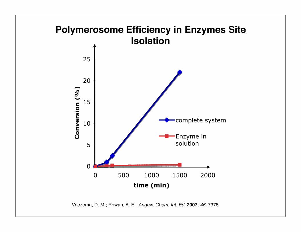
Putting Enzymes in Membrane & Internal Water Pool of Polymersome
Vriezema, D. M.; Rowan, A. E. Angew. Chem. Int. Ed. 2007, 46, 7378
aqueous solution of enzyme 1
PS-PIAT in THF
LyophilizationPowder
redissolved in THF
enzyme 1
Lyophilization
Powder
aqueous solutionof enzyme 2
Injec
tion
enzyme 2
enzyme 1
enzyme 2
enzyme 1
water

CALB: Candida antarctica lipase B
HRP: Horseradish peroxidase
GOX: Glucose oxidase
Proof of Principle of Enzymatic Encapsulation
Vriezema, D. M.; Rowan, A. E. Angew. Chem. Int. Ed. 2007, 46, 7378
OOH
HO OH
HO
HOO
O
HO OH
HO
HO
O2GOX H2O2
OOH
HO OH
HO
HOO
OH
OAcAcO
AcO
AcOCALB
H2O
N
SN
SO
O
HON
N
S SO
O
OH
H2O2 N
SN
SO
O
HON
N
S SO
O
OH
2H2O2 2
(ABTS) (ABTS)
HRP

Vriezema, D. M.; Rowan, A. E. Angew. Chem. Int. Ed. 2007, 46, 7378
OO
OHHO
HO
HO
H2O2
2ABTS H2O2
GOX
CALB
OOH
OO
OO
OO
OO
OOH
OHHO
HO
HO
2H2ON
SN
SO
O
HON
N
S SO
O
OH
2
HRP
Vriezema, D. M.; Rowan, A. E. Angew. Chem. Int. Ed. 2007, 46, 7378
0
5
10
15
20
25
0 500 1000 1500 2000
time (min)
Co
nvers
ion
(%
)
complete system
Enzyme insolution
Polymerosome Efficiency in Enzymes Site Isolation
• Wolf and lamb multicatalyst sequential one-pot reactions can decrease the number of purification steps.
• Site isolation of wolf and lamb catalyst is essential
• The catalysts can be site isolated on solid polymer, nanoparticles or microcapsules
• Site isolated catalysts should be porous enough for reagent diffusion
• Site Isolation has to be efficient enough to keep catalysts trapped inside itself.
Conclusions

Acknowledgements
Dr. Borhan
Dr. Baker Dr. Jackson
Chrysoula, Marina, Dan, Xiaofei, Stewart, Sing, Xiaoyong, Aman, Toyin, Calvin, Wenjing, Atefeh,
Mercy, Arvind, Camille, Carmin, Sarah
Afra, Aman, Behnaz, Behrooz, Dima, Luis, Maryam, Rafida, Ramin


