the result of bad design or fabrication, although those two areas are sometimes blamed for any problems that arise. To assure that those areas do not contribute to unacceptable or dangerous situations, the Design Professional should: 1. Confirm that the correct Codes and Loads are specified. It is amazing to see 25 PSF roof loads specified on professionally developed plans for construction in areas of northern New England that require 60 or 70 PSF net loads. Check and analyze for drift conditions in snow areas. Make sure that the latest Code and Standards are used as a basis for unbalanced and wind load situations. 2. Get to know the Fabricators. The software used to design the trusses must be in the hands of competent, experienced technicians. The Fabricator should have a good QA program in place. With IBC Code Chapter 17 (Special Inspections) requirements, the Truss Plate Institute (TPI) or other Third Party Inspection program should be something that is required. Otherwise, follow the Code and put an Owner’s Inspector in the plant during fabrication of the trusses. Preventing damage to the product before and after installation are obvious precautions that must be made with any product. Damage to the structure by sub-contractors can produce serious conditions, but the vast majority of difficulties with metal plate connected trusses come from poor handling and bracing of the product. Proper Truss installation is more than just getting the correct component into the right location in the proper orientation without damaging it. These essentially two-dimensional components must be braced sufficiently or the whole system may come down. STRUCTURE magazine • March 2005 31 The Metal Plate Connected Wood Truss as we know it has been around for about 50 years. It has been in common and wide use for the last thirty. It is a very important component of the wood frame building business, and the science of its design and use is quite well understood. Wood trusses are a product that are used by millions with no difficulties, and often perform beyond what would be expected of a structural component that is sometimes abused and rarely installed completely according to the rules. Why then, are there concerns about how to keep them from falling down? With the increasing complexity of designs, and the increasing expectations of accuracy in computer aided design, the building designer is increasingly pushing the limits of structural components. This is no truer than in the use of wood trusses. The concerns regarding the use of wood trusses come mainly from the lack of understanding of the building team’s responsibilities: much of the critical work is expected to be someone else’s job. Installation accidents and structural failures are preventable. Proper bracing of trusses is critical to safety of the workers during erection, and proper bracing is required to make the trusses produce their design capacity. Additionally, adequate permanent bracing is necessary to enable the building to function as a structural system to resist all loads for which it is designed. Where do the problems come from? The problems with wood truss systems are often greatly misunderstood. They are rarely Inadequate Bracing of Trusses Whose Job is it Anyway By Josh Bartlett Wood Truss Bracing
Transcript
the result of bad design or fabrication, although those two areas are sometimes blamed for any problems that arise. To assure that those areas do not contribute to unacceptable or dangerous situations, the Design Professional should:
1. Confirm that the correct Codes and Loads are specified. It is amazing to see 25 PSF roof loads specified on professionally developed plans for construction in areas of northern New England that require 60 or 70 PSF net loads. Check and analyze for drift conditions in snow areas. Make sure that the latest Code and Standards are used as a basis for unbalanced and wind load situations.
2. Get to know the Fabricators. The software used to design the trusses must be in the hands of competent, experienced technicians. The Fabricator should have a good QA program in place. With IBC Code Chapter 17 (Special Inspections) requirements, the Truss Plate Institute (TPI) or other Third Party Inspection program should be something that is required. Otherwise, follow the Code and put an Owner’s Inspector in the plant during fabrication of the trusses.
Preventing damage to the product before and after installation are obvious precautions that must be made with any product. Damage to the structure by sub-contractors can produce serious conditions, but the vast majority of difficulties with metal plate connected trusses come from poor handling and bracing of the product. Proper Truss installation is more than just getting the correct component into the right location in the proper orientation without damaging it. These essentially two-dimensional components must be braced sufficiently or the whole system may come down.
STRUCTURE magazine • March 2005 31
The Metal Plate Connected Wood Truss as we know it has been around for about 50 years. It has been in common and wide use for the last thirty. It is a very important component of the wood frame building business, and the science of its design and use is quite well understood. Wood trusses are a product that are used by millions with no difficulties, and often perform beyond what would be expected of a structural component that is sometimes abused and rarely installed completely according to the rules.
Why then, are there concerns about how to keep them from falling down? With the increasing complexity of designs, and the increasing expectations of accuracy in computer aided design, the building designer is increasingly pushing the limits of structural components. This is no truer than in the use of wood trusses. The concerns regarding the use of wood trusses come mainly from the lack of understanding of the building team’s responsibilities: much of the critical work is expected to be someone else’s job.
Installation accidents and structural failures are preventable. Proper bracing of trusses is critical to safety of the workers during erection, and proper bracing is required to make the trusses produce their design capacity. Additionally, adequate permanent bracing is necessary to enable the building to function as a structural system to resist all loads for which it is designed.
Where do the problems come from?
The problems with wood truss systems are often greatly misunderstood. They are rarely
WTCA documents. Keeping the trusses in the proper in-plane
orientation, and keeping the members from buckling before the lateral and permanent bracing are installed, is absolutely critical. Bracing the products during handling using strongbacks or other handling method should prevent damage. As the trusses are being set, bracing the products properly with adequate materials is one of the most important things that the truss installer should do. Trying to restrain a 300 to 400 lb. truss that has a high center of gravity with a 25-inch long piece of 1x3 spruce is commonly done, often with disastrous results. These have become known as “Killer Cleats,” and should not be allowed on the job. Without longer length 2x4 lumber or one of the available patented metal braces restraining the truss, it can become unstable and simply fall over, occasionally with fatal results. Keeping the products straight and vertical is essential to prevent these very dangerous “domino effect” toppling accidents. Even without personal injury, the damage to the product and their supports is very serious. A truss that has been bent dramatically out of plane, or has been dropped, should be rejected and replaced. Walls, floors, and beams lines will need to be inspected and perhaps repaired if trusses have fallen and induced high loads or displaced these elements.
There are very good documents available from the Wood Truss Council of America (WTCA) that address various suggestions and
recommendations that have been developed over the years to prevent damage in handling and reduce possibilities of toppling accidents. The BCSI series is available as a booklet from WTCA, and individual BCSI sections are usually delivered to the jobsite with the trusses and as part of the submittal package
those requirements.Compression web member bracing is an-
other area that should also be clearly shown on the truss design drawings that are submitted by the Fabricator. This is an area where the experience and talent of the truss designer can dramatically affect the installed cost of a truss. Using slender, low grade materials for those members will reduce the price of the component, but the requirement of more lateral bracing can raise the installed cost significantly. Fabricators do not generally supply the bracing materials in their packages, so the cost of the bracing material and install-
ation remain s o m e w h a t hidden. The Fabr i ca to r may show the size, location,
and grade of this required compression web lateral bracing on the design drawings, although it is not the Truss Designer or Fabricator’s responsibility under the ANSI/TPI 1-2002 National Design Standard for Metal Plate Connected Wood Truss Construction. That document states that the Truss Designer only need to notify the Building Designer as to the need for and “….approximate location of….” (2.1.2.12) the bracing assumed in the design of the individual component and the fabricator is only required to provide that the members be “….clearly marked to call attention to the need for such field bracing…” (2.4.4.3). That information should be clearly communicated to the crew installing the trusses, typically with tags on the members that need lateral bracing, as well as being shown on the truss design drawings.
Generally, construction grade 2x4 or 2x6 lumber, or one of the proprietary metal braces, is used as brace material on compression webs and unsheathed chord members. This critical bracing is sometimes only identified on the truss “calc” sheet, and neglect of this bracing will sometimes lead to the truss system collapsing under minimal loads. The Fabricator also needs to communicate the forces that may be developed in the web so that compression bracing connection and anchorage may be taken into consideration by the Building Designer. Generally, 2% of the web compression force is considered to be generated at each braced member.
Contractor Bracing ResponsibilitiesBracing required for installation of the
components is considered part of “Means and Methods” and is clearly best made the responsibility of the people installing the trusses. Again, this is stated in the ANSI/TPI/
STRUCTURE magazine • March 2005 32
ANSI/TPI-1-2002 National Design Standards
Three Types of Bracing- Three Areas of Responsibility
There are three types of bracing required in a wood truss system, and all are essential to the safe installation and structural adequacy of the system. The lateral bracing keeps the compression members from buckling and failing; the installation bracing holds the truss in place during construction; and the permanent bracing provides anchorage and stability for the whole system so it may resist all the loads for which it is designed, including gravity, wind, seismic, and other forces.
The failures that occur are almost always the result of someone not understanding their responsibility for some category of bracing. Those general areas of responsibility are, unless specified otherwise, stated in the ANSI/TPI/WTCA 4-2002 and the ANSI/TPI 1-2002 documents that are referenced in IBC and other building codes. Those documents delineate three members of the project team – the Truss Fabricator and Designer, the Contractor, and the Building Designer – and identify the responsibilities of each.
It is the duty of the Building Designer, if supervising the construction as an agent of the owner, to see that the requirements of each member of the project team acknowledge and follow those areas of responsibility.
Truss bracing that resists buckling of individual component compression members is the responsibility of the Truss Designer, who is usually on the staff of or under contract with the Fabricator, and is charged with designing the individual truss component. Buckling failures of slender members in compression are dangerous because of their catastrophic nature and must be resisted in these two-dimensional components with bracing. The Truss Designer takes the lateral restraint of these members into consideration when choosing the size and properties of the members. Top chords are usually, but not always, braced by roof sheathing acting as a diaphragm. The truss design drawing should show the maximum unbraced length of the top chord.
Bottom chord major forces are usually only tension loads, so the bracing of the component is minimal unless there is a cantilever or other force reversing situation. In these cantilever force reversals or exposed overhang situations producing wind induced uplift, the bracing requirements may become quite involved. A responsible Fabricator will clearly identify
...three members of the project team — the Truss Fabricator and Designer, the
by the Fabricator. Installation of larger (60-foot+) or atypical trusses require a thorough, well considered, individually designed scheme for handling and bracing. Many Fabricators recommend that a Structural Engineer design and supervise the procedures for bracing and handling such trusses.
Building Designer Bracing Responsibilities
As the Building Designer is responsible for the design of the permanent bracing of the overall structural system of the building, the Building Designer is responsible for incorporating the individual components, including the wood trusses, into the overall structure. The Building Designer has determined the gravity loads, and the lateral forces and uplift, and must design a system that ties the structure together so that it may act to resist all of those forces and maintain stability in whatever combination they occur. Often, roof and floor planes are used to resist forces, through bracing to the exterior walls, shear walls and beam lines.
The permanent bracing system must also hold the components in place. A truss out of vertical or one that has been allowed to move out of flat plane is one that very well may not meet design capacity.
The installation bracing may be left in place and may be used as part of the permanent bracing system, but only after the Build-ing Designer determines what has actually been used. A better alternative would have the Building Designer develop a permanent bracing plan that incorporates the use of an installation bracing method developed in cooperation with the Contractor. This could make for more efficient, cost effective construction.
The permanent bracing must also provide anchorage for any required lateral bracing. The lateral bracing load from the individual web members may be quite small, but the accumulation of these small forces through a system that may have 50 or 100 or more repetitions, as occurs in a long truss framed
building, can add up to a large amount of force. Also, gable end frames (often incorrectly called trusses) are usually studded with members on the flat, so that their wind load resisting capacity is quite small. These members may need to be braced to an anchor point, or “T” bracing should be installed.
Additionally, there should be a responsible experienced individual designated to check that all the required permanent and lateral bracing has been installed according to the plan. Although obvious, this is an inspection requirement that should be clearly specified in the project documents by the Building Designer. Neglect of this one detail has been responsible for building failures. For example, failure to properly install compression web lateral bracing and the anchorage for that bracing
can reduce the truss capacity by as much as 90%! This installation review should be performed after the mechanical trades are complete, as they are often responsible for damage to or removal of required bracing. In the larger buildings, particularly if a Design Professional has developed the bracing system, this installation review should be done by the Building Designer.
What if there is no Building Designer?By Code and Standards, there is no such
thing as a structure without a Building Designer. The responsibilities outlined fall on the Building Owner if there is no Professional designated by the owner. Often, the Code will require the owner engage the services of a Professional Designer.
Many times, an Architect or other Prof-essional will assume that the structure does not need to be reviewed by a Structural Engineer because one or more components are “engineered”. On most buildings, this is clearly false and dangerous. Assuming that the Truss Fabricator has reviewed all those areas that may affect the building design is like expecting the supplier of the basement columns will track all the loads to their product. Like structural steel fabricators, Truss Fabricators will expect that the plans and specifications, and the approval process of their product (if required) will provide them with the requirements for the product they provide.
In some parts of the country, some fabricators are accepting the overall building design responsibility. This overall “package approach”, even including installation of the products, is becoming more common, but most often as a separate contract with their
own designated Structural Engineer taking the responsibility for design and supervision.
ConclusionIf the Design Professional, in communica-
tion with the Component Fabricator and the Contractor, requires that all team members un-derstand and meet their responsibilities in the area of proper bracing and handling of trusses, jobsite accidents and structural failures will be reduced. In doing so, we will be taking advantage of the benefits that a wood truss sys-tem can provide to our clients, producing safer jobsites, and eliminating some of the surprises that we all would choose to avoid.▪
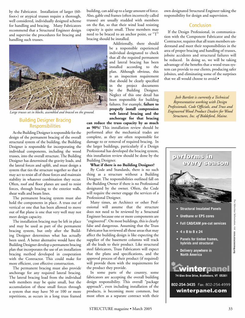
Large trusses set in blocks, assembled and braced on the ground.
Josh Bartlett is currently a Technical Representative working with Design
Professionals, Code Officials, and Truss and Engineered Wood Product Dealers for Wood
The following is a broad overview of truss bracing issues, and how both the structural engineering community and the truss industry look at bracing design and the implementation of that design. Our industry always welcomes a healthy exchange of ideas, where the view-points of all structural engineers and suppliers of engineered building products can be more thoroughly understood. This will help us design and build safe, reliable and economical structures more easily.
The recurring theme in much of the dis-cussion between the structural engineering community and the wood truss industry revolves around who should be tending to the permanent bracing design for the roof, floor or wall system. Oftentimes, the perspective of the structural engineering community is that:
1. All temporary bracing and all permanent bracing design should be part of the sealed truss shop drawings, or what our industry calls truss design drawings.
2. There is an expectation that this is the responsibility of the Truss Designer, which then flows through to the Truss Manufacturer because they are the interface with both the Building Designer and the Contractor.
The IBC 2003 code adopted ANSI/TPI 1-2002 Chapter 2 states that, regarding con-struction permanent bracing responsibilities:
• Section 2.5.2: “The Building Designer, through the Structural Design Documents shall provide information sufficiently accurate and reliable to be used for facilitating the supply of the Structural Elements and for developing the design of the Trusses for the Building, and shall provide the following:…..”
• Section 2.5.2.9: “Permanent bracing design for the Building, including bracing to resist wind, seismic, or other lateral forces, and permanent bracing for all Structural Elements and Trusses. The permanent brac-ing design shall incorporate the continuous lateral chord and web member bracing that is designated on the individual Truss Design Drawings into the overall bracing for the entire Building Structural System.”
• To further define responsibilities, Section 2.6.5: “The Truss Manufacturer and Truss Designer are not responsible for, nor do the Truss Manufacturer and Truss Designer have control of, construction means, methods, techniques, sequences, procedures, programs and
One might say that this approach to design is not very logical or safe, in a construction process that should be both logical and safe for all involved.
As stated above, our industry has produced BCSI 1-03 to provide guidance on both temporary and permanent bracing issues. Figures 1 and 2 provide a brief perspective on the treatment of permanent bracing within BCSI.
There are a few truss installation conditions where the top chord may not have sheathing applied and needs permanent bracing. A good example of this condition is called a piggyback truss, as shown in Figure 3.
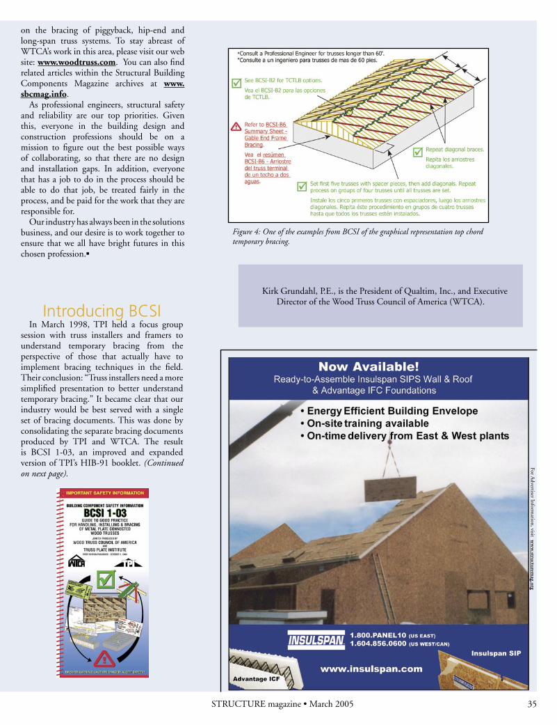
The easiest permanent bracing solution for piggyback type trusses is to turn any of the top chord temporary lateral and diagonal bracing methods into the permanent bracing for the piggyback top chord. Figure 4 provides
one of the BCSI examples of temporary top chord bracing that could easily be designed to become permanent top chord bracing.
As stated above, a key gap in the construction process is often the design and installation of the permanent lateral and diagonal bracing. Our industry’s emphasis on this aspect of bracing is intended to help focus attention on this issue. We are now in the process of working on the second edition of BCSI 1-03, where we will provide additional information
safety in connection with the handling, storing, installation and bracing of the Trusses. These topics are covered in the BCSI 1-03: Guide to Good Practice for Handling, Installing & Bracing of Metal Plate Connected Wood Trusses,” and
• Section 2.6.6: “The Truss Manufacturer and Truss Designer shall not be responsible for the design, materials, or installation of per-
manent bracing for the Building, in-cluding bracing for all or any of the Trusses and Struc-tural Elements. The
approximate location for, or the maximum spacing between, permanent lateral bracing of Truss members will be indicated on the Truss Design and it shall be the responsibility of the Owner to engage the Building Designer or others to specify how the permanent lat-eral bracing is to be anchored or restrained to prevent lateral movement of all Truss members together. Consideration shall be given to one of the following methods for providing this restraint or anchorage: (a) permanent diago-nal bracing in the plane of the Truss members; or (b)other means when demonstrated by the Building Designer or other qualified person to provide equivalent lateral resistance.”
When one thinks about the construction process, the text referenced above provides reasonably logical areas of responsibility based on the specific expertise and skill of all the parties involved. However, the world in which we live often allows trusses to be deferred submittals, or the Structural Design Documents state “trusses designed by others.” This results in a gap in the design process because the building design is completed before the design of the trusses is contemplated.
STRUCTURE magazine • March 2005 34 STRUCTURE magazine • March 2005
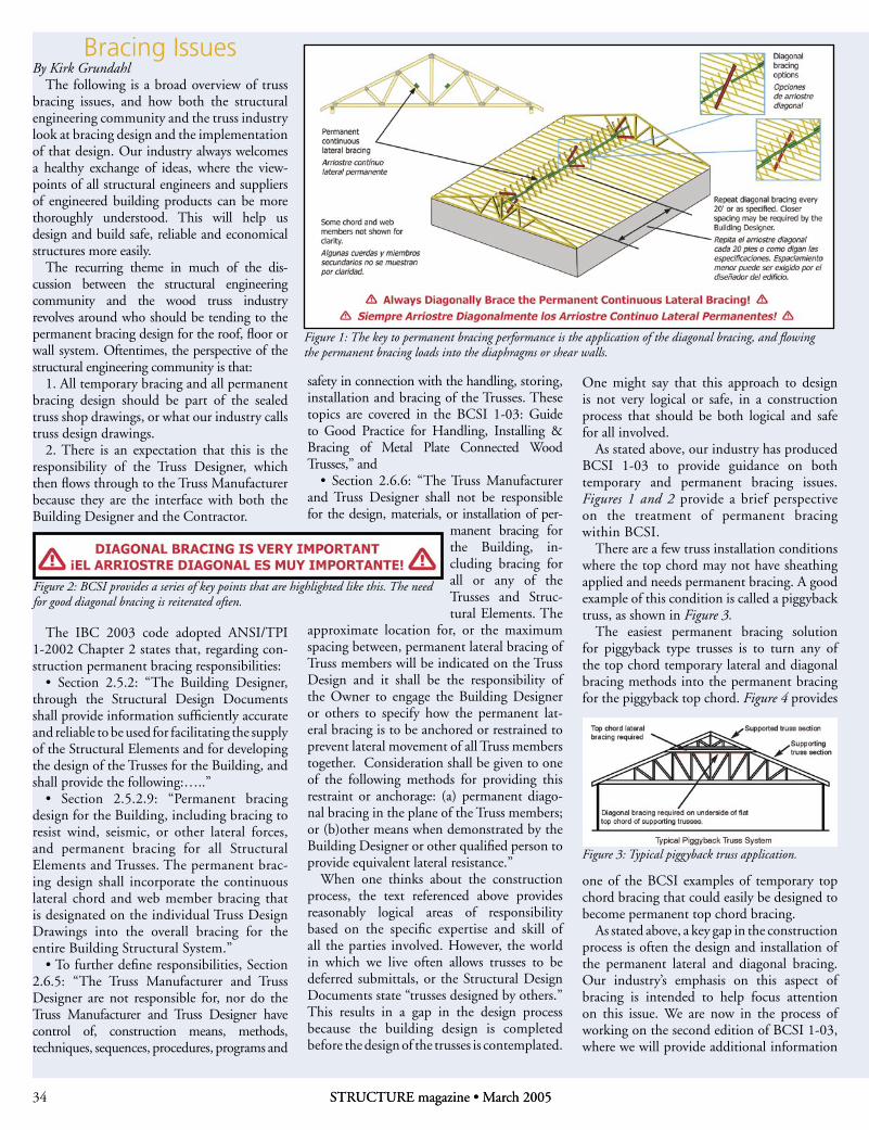
Figure 2: BCSI provides a series of key points that are highlighted like this. The need for good diagonal bracing is reiterated often.
Figure 3: Typical piggyback truss application.
Figure 1: The key to permanent bracing performance is the application of the diagonal bracing, and flowing the permanent bracing loads into the diaphragms or shear walls.Copyright
Figure 4: One of the examples from BCSI of the graphical representation top chord temporary bracing.
on the bracing of piggyback, hip-end and long-span truss systems. To stay abreast of WTCA’s work in this area, please visit our web site: www.woodtruss.com. You can also find related articles within the Structural Building Components Magazine archives at www.sbcmag.info.
As professional engineers, structural safety and reliability are our top priorities. Given this, everyone in the building design and construction professions should be on a mission to figure out the best possible ways of collaborating, so that there are no design and installation gaps. In addition, everyone that has a job to do in the process should be able to do that job, be treated fairly in the process, and be paid for the work that they are responsible for.
Our industry has always been in the solutions business, and our desire is to work together to ensure that we all have bright futures in this chosen profession.▪
Kirk Grundahl, P.E., is the President of Qualtim, Inc., and Executive Director of the Wood Truss Council of America (WTCA).
Introducing BCSIIn March 1998, TPI held a focus group
session with truss installers and framers to understand temporary bracing from the perspective of those that actually have to implement bracing techniques in the field. Their conclusion: “Truss installers need a more simplified presentation to better understand temporary bracing.” It became clear that our industry would be best served with a single set of bracing documents. This was done by consolidating the separate bracing documents produced by TPI and WTCA. The result is BCSI 1-03, an improved and expanded version of TPI’s HIB-91 booklet. (Continued on next page).
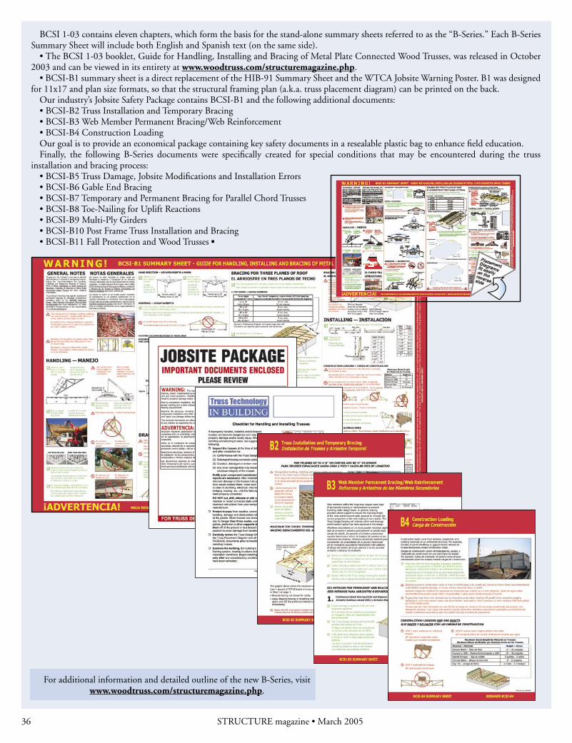
BCSI 1-03 contains eleven chapters, which form the basis for the stand-alone summary sheets referred to as the “B-Series.” Each B-Series Summary Sheet will include both English and Spanish text (on the same side).
• The BCSI 1-03 booklet, Guide for Handling, Installing and Bracing of Metal Plate Connected Wood Trusses, was released in October 2003 and can be viewed in its entirety at www.woodtruss.com/structuremagazine.php.
• BCSI-B1 summary sheet is a direct replacement of the HIB-91 Summary Sheet and the WTCA Jobsite Warning Poster. B1 was designed for 11x17 and plan size formats, so that the structural framing plan (a.k.a. truss placement diagram) can be printed on the back.
Our industry’s Jobsite Safety Package contains BCSI-B1 and the following additional documents:• BCSI-B2 Truss Installation and Temporary Bracing • BCSI-B3 Web Member Permanent Bracing/Web Reinforcement • BCSI-B4 Construction Loading Our goal is to provide an economical package containing key safety documents in a resealable plastic bag to enhance field education.Finally, the following B-Series documents were specifically created for special conditions that may be encountered during the truss
installation and bracing process:• BCSI-B5 Truss Damage, Jobsite Modifications and Installation Errors • BCSI-B6 Gable End Bracing • BCSI-B7 Temporary and Permanent Bracing for Parallel Chord Trusses • BCSI-B8 Toe-Nailing for Uplift Reactions • BCSI-B9 Multi-Ply Girders • BCSI-B10 Post Frame Truss Installation and Bracing • BCSI-B11 Fall Protection and Wood Trusses ▪
For additional information and detailed outline of the new B-Series, visit www.woodtruss.com/structuremagazine.php.