Work Functions of Functionalized Single-Walled Carbon Nanotubes by Janet Ryu SUBMITTED TO THE DEPARTMENT OF MATERIALS SCIENCE AND ENGINEERING IN PARTIAL FULFILLMENT OF THE REQUIREMENTS FOR THE DEGREE OF BACHELORS OF SCIENCE IN MATERIALS SCIENCE AND ENGINEERING AT THE MASSACHUSETTS INSTITUTE OF TECHNOLOGY MAY 2006 c 2006 Janet S. Ryu. All rights reserved. The author hereby grants to MIT permission to reproduce and to distribute publicly paper and electronic copies of this thesis document in whole or in part in any medium now known or hereafter created. Signature of Author: ..................................................................... Department of Materials Science and Engineering May 26, 2006 Certified by: ............................................................................. Nicola Marzari Professor of Materials Science and Engineering Thesis Supervisor Accepted by: ............................................................................ Caroline Ross Professor of Materials Science and Engineering Chairman, Committee for Undergraduate Students 1
Transcript
Work Functions of Functionalized Single-Walled Carbon Nanotubes
by
Janet Ryu
SUBMITTED TO THE DEPARTMENT OFMATERIALS SCIENCE AND ENGINEERING IN PARTIAL
FULFILLMENT OF THE REQUIREMENTS FOR THEDEGREE OF
BACHELORS OF SCIENCE IN MATERIALS SCIENCE AND ENGINEERING
1.2 Armchair (left) and zigzag (right) nanotubes. The red outlines the armchairand zigzag patterns going around the tube. [14] . . . . . . . . . . . . . . . . 8
1.3 Schematic showing some of the different possible (n, m) nanotubes that can
be rolled. The red vectors show the vector ~R that will produce a zigzag orarmchair nanotube. All of the nanotubes formed from rolling along any othervector ~R will be chiral. The blue and green circles denote where the greencircle labeled (0,0) would be superimposed in order to get that particularnanotube.[15] . . . . . . . . . . . . . . . . . . . . . . . . . . . . . . . . . . . 8
1.4 Illustration of the work function definition.[5] . . . . . . . . . . . . . . . . . 9
3.1 Models of the pristine (5,0) and (5,5) SWNTs. . . . . . . . . . . . . . . . . . 193.2 Models of the fully hydrogenated (5,0) SWNT. . . . . . . . . . . . . . . . . . 193.3 Models of the fully hydrogenated (5,5) SWNT. . . . . . . . . . . . . . . . . . 193.4 Models of the two different configurations of a (5,5) SWNT functionalized with
two hydrogens. Throughout this study, these two functionalized nanotubeswill be differentiated as configurations 1 and 2. . . . . . . . . . . . . . . . . . 20
3.5 Model of (5,5) SWNT functionalized with an aminophenyl group. . . . . . . 203.6 Simple tetagonal lattice. Lattice constants are a and c, where a 6=c.[6] . . . . 213.7 Geometry of a (5,0) CNT described as a 20-carbon ring within a unit cell.
All of the nanotubes were described as rings, which could be repeated to forma tube (See Figures 3.1-3.4). Calculations were performed on the geometriesdescribed within a unit cell. . . . . . . . . . . . . . . . . . . . . . . . . . . . 22
3.8 Unit cell of the (5,0) CNT repeated along the z-axis. The white outlinesdenote the outline of the unit cell. The empty space is necessary, because theunit cell can be repeated along the x, y, and z axes. There must be enoughvacuum space around the ring so they do not interact with each other whenrepeated along the x and y axes. . . . . . . . . . . . . . . . . . . . . . . . . . 22
3
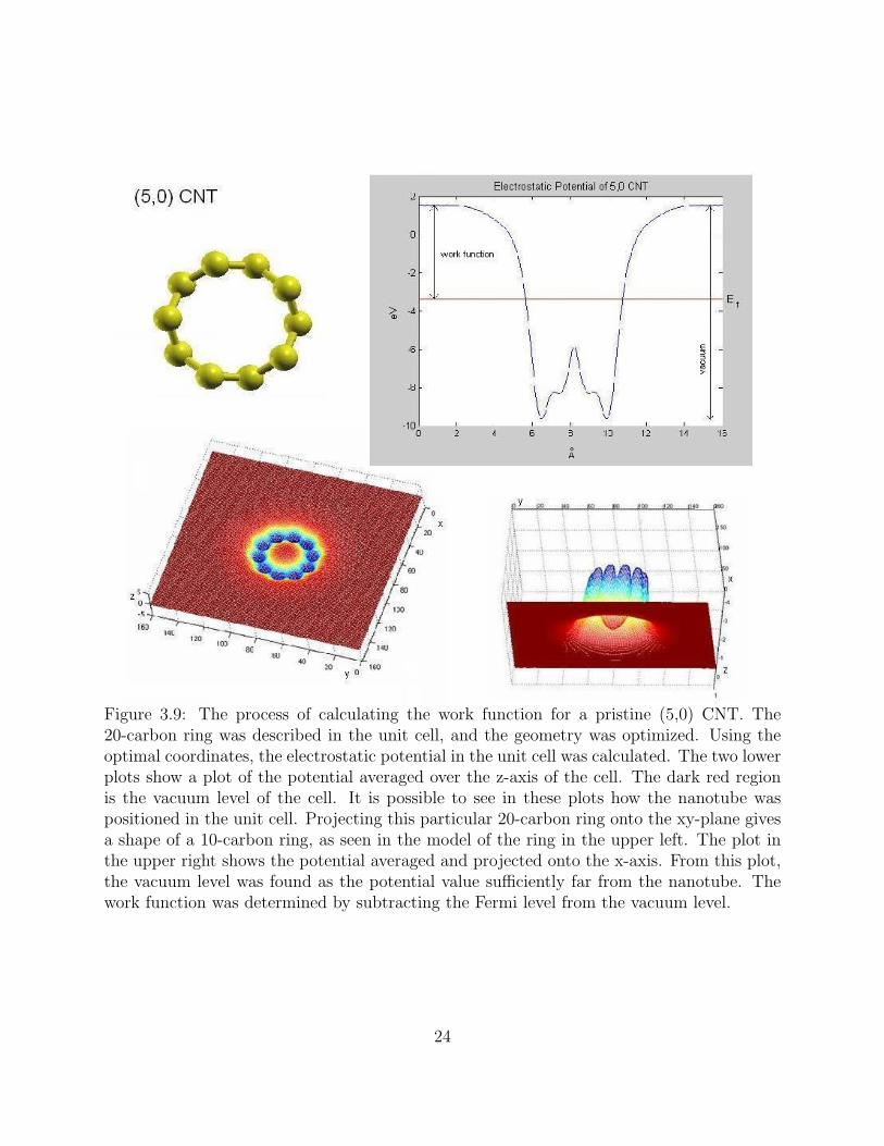
3.9 The process of calculating the work function for a pristing (5,0) CNT. The20-carbon ring was described in the unit cell, and the geometry was optimized.Using the optimal coordinates, the electrostatic potential in the unit cell wascalculated. The two lower plots show a plot of the potential averaged over thez-axis of the cell. The dark red region is the vacuum level of the cell. It ispossible to see in these plots how the nanotube was positioned in the unit cell.Projecting this particular 20-carbon ring onto the xy-plane gives a shape of a10-carbon ring, as seen in the model of the ring in the upper left. The plot inthe upper right shows the potential averaged and projected onto the x-axis.From this plot, the vacuum level was found as the potential value sufficientlyfar from the nanotube. The work function was determined by subtracting theFermi level from the vacuum level. . . . . . . . . . . . . . . . . . . . . . . . 24
4.1 Planar average of the electrostatic potential along the x-axis for the pristine(5,0) CNT. . . . . . . . . . . . . . . . . . . . . . . . . . . . . . . . . . . . . . 27
4.2 Planar average of the electrostatic potential along the x-axis for the fullyhydrogenated (5,0) CNT. . . . . . . . . . . . . . . . . . . . . . . . . . . . . . 28
4.3 Planar average of the electrostatic potential along the x-axis for the pristine(5,5) CNT. . . . . . . . . . . . . . . . . . . . . . . . . . . . . . . . . . . . . . 28
4.4 Planar average of the electrostatic potential along the x-axis for the fullyhydrogenated (5,5) CNT. . . . . . . . . . . . . . . . . . . . . . . . . . . . . . 29
4.5 Planar average of the electrostatic potential along the x-axis for the pristine(5,5) CNT functionalized with 2 hydrogens (Configuration 1). . . . . . . . . 29
4.6 Planar average of the electrostatic potential along the x-axis for the pristine(5,5) CNT functionalized with 2 hydrogens (Configuration 2). . . . . . . . . 30
4.7 Planar average of the electrostatic potential along the x-axis for the (5,5) CNTfunctionalized with an aminophenyl group. . . . . . . . . . . . . . . . . . . . 30
4.8 Relaxation of a (5,5) CNT functionalized with 2 hydrogens. The structure wasunstable when the nanotube was defined with only 20 carbons. 60 carbonswere necessary to have an energetically stable structure when functionalizingwith two hydrogens. . . . . . . . . . . . . . . . . . . . . . . . . . . . . . . . 31
4.9 Relaxation of a (5,5) CNT functionalized with 4 hydrogens. The structurewas unstable when the nanotube was defined with only 20 carbons. Relaxingthis nanotube resulted in its splitting. . . . . . . . . . . . . . . . . . . . . . . 32
4.10 Band structure for the pristine (5,0) CNT. . . . . . . . . . . . . . . . . . . . 344.11 Band structures for the pristine (5,5) CNT on the left and the fully hydro-
genated (5,5) CNT on the right. . . . . . . . . . . . . . . . . . . . . . . . . . 354.12 Band structures for the (5,5) CNT functionalized with 2 hydrogens. Config-
uration 1 on the left, and configuration 2 on the right. . . . . . . . . . . . . . 35
4
Chapter 1
Introduction
1.1 Carbon nanotubes
Carbon nanotube (CNT) structures were discovered by Sumio Iijima in 1991 at NEC lab-
oratories in Japan. Since their discovery, scientists and engineers have been fascinated by
their electrical and mechanical properties. Their unique characteristics, in addition to their
nanoscale size, have generated much excitement about the possible applications of this novel
material.
This excitement surrounding carbon nanotubes came after the discovery of fullerenes,
with C60 being the dominant species. In 1985, Harry Kroto and Richard Smalley and cowork-
ers were studying the vaporization of graphite when they discovered this stable, ordered
formation of carbon. Previously, graphite and diamond were the only structures carbon was
known to form. Conducting research on C60 proved to be difficult at this point, because
there was no known method of producing it in bulk. This problem was remedied with the
work of Wolfgang Kratschmer and Donald Huffman and colleagues, who published their re-
sults in 1990. A carbon arc could be used to vaporize graphite within a chamber of helium.
The soot that got deposited on the walls of the chamber during the vaporization contained
5
C60 in large enough amounts that they could now be studied. More importantly, this arc
vaporization process was simple enough that any lab could perform it.[4]
After this Kratschmer-Huffman paper, Iijima began studying the soot for possible other
carbon formations and found that most of the soot off the chamber wall was amorphous and
not stable carbon structures. He then looked at the deposit formed on the graphite cathode,
and it was here that he discovered the nanotube structures.
1.1.1 Properties
Carbon nanotubes can be thought of as a rolled-up sheet of graphite, capped with half a C60
molecule on each end. They can be multi-walled or single-walled. A single-walled carbon
nanotube (SWNT) has a diameter around 1nm, while a multi-walled nanotube (MWNT)
can have an outer diameter ranging from 2.5nm to 30nm.[4]
Carbon nanotubes can be conducting, semi-conducting, superconducting, and insulating.
Some nanotubes appear to exhibit ballistic conduction along the tube, which is a charac-
teristic of a quantum wire.[4] Ballistic conduction or transport is when electrons are able
to flow without colliding into impurities or being scattered by phonons. The electrons are
not slowed down, and energy is not lost in the form of heat; essentially, there is resistance
free conduction along the tube. While ballistic conduction occurs only in certain nanotubes,
generally, nanotubes conduct as well as copper, if not better.
Nanotubes also exhibit incredible tensile strength. They are comprised entirely of sp2
hybridized bonds, which are even stronger than the sp3 hybridized bonds of diamond. A
MWNT was measured to have a tensile strength of 63GPa in 2000.[16] This is an order of
magnitude higher than the tensile strength of steel, 1.2GPa. Nanotubes have low density,
making their tensile strength appear even more impressive. Their Young’s modulus is around
1000GPa[2], which is about 5 times greater than that of steel. In compression, nanotubes
do not do well and tend to buckle.
6
Figure 1.1: Schematic showing the vector notation used for differentiating carbon nanotubes.[1]
1.1.2 Structure notation
The properties of a nanotubes depend greatly on the chirality, or twist, of the nanotube. A
schematic of how this chirality is determined can be found in Figure 1.1.
Every carbon atom on the hexagonal lattice can be represented as a sum of two vectors
~a1 and ~a2. Forming a nanotube can be thought of as putting atom A in the same location as
atom B, by rolling the graphene along vector ~R. Vector ~R is represented by the following:
~R = n~a1 + m~a2 (1.1)
The chirality and size of a nanotube depend on the values of the coefficents n and m in
Equation 1.1. They are also used in the naming of a nanotube. For example, a vector with
the coefficents of n=7 and m-4 would yield a (7,4) nanotube. In general, if n−m3
is an integer,
that nanotube is metallic; therefore, about a third of all nanotubes are metallic.
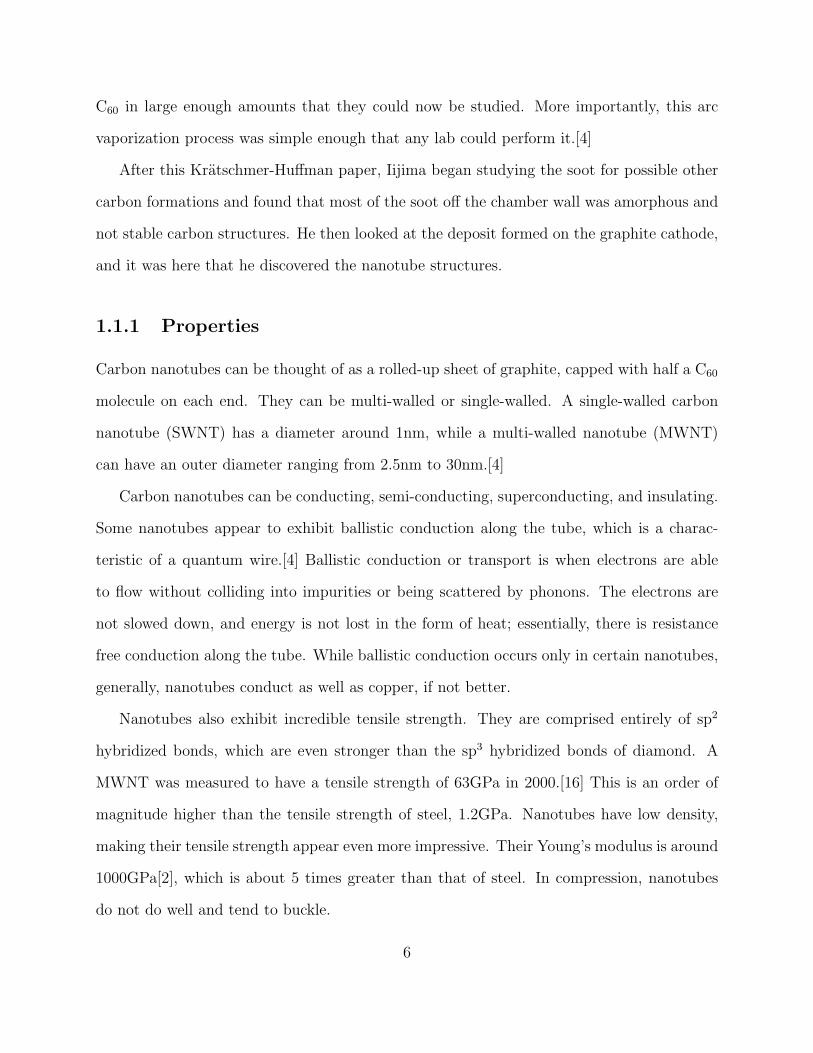
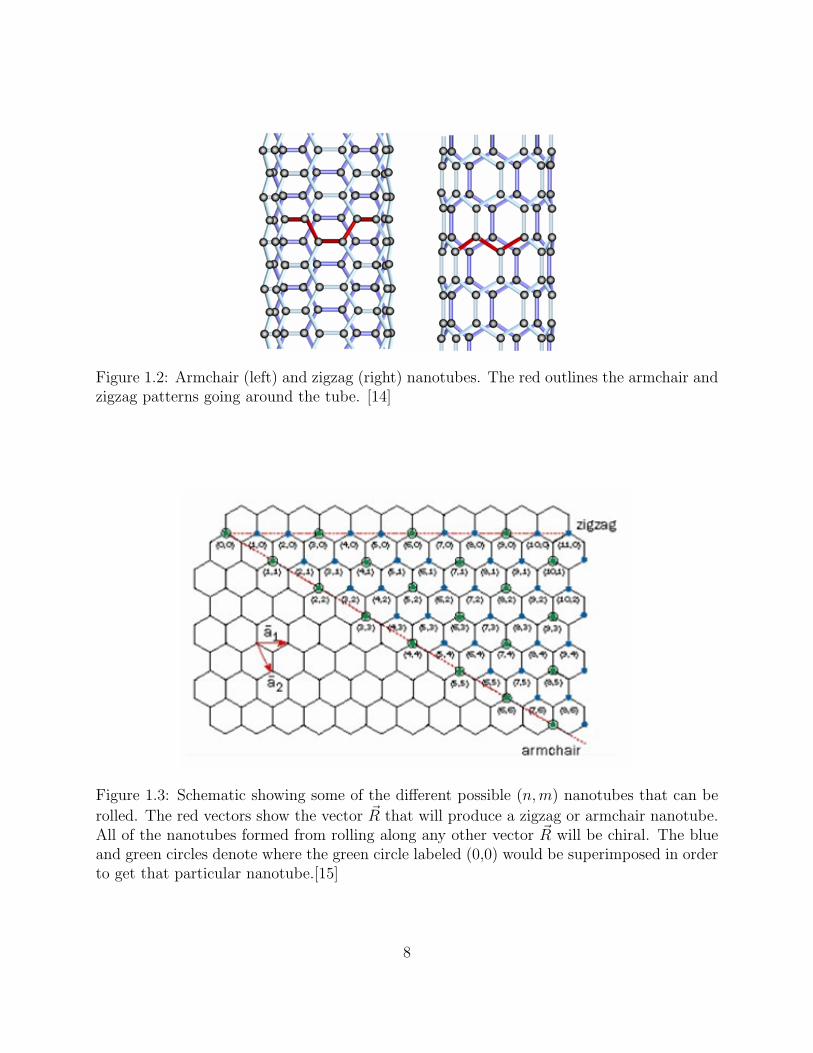
There are two special kinds of CNTs, armchair and zigzag, shown in Figure 1.2. Armchair
CNTs are (n, n) CNTs, while zigzag CNTs are (n, 0). Figure 1.3 shows the vector ~R for a
zigzag or armchair nanotube and how the resulting tube would have the carbons in a zigzag
7
Figure 1.2: Armchair (left) and zigzag (right) nanotubes. The red outlines the armchair andzigzag patterns going around the tube. [14]
Figure 1.3: Schematic showing some of the different possible (n,m) nanotubes that can be
rolled. The red vectors show the vector ~R that will produce a zigzag or armchair nanotube.All of the nanotubes formed from rolling along any other vector ~R will be chiral. The blueand green circles denote where the green circle labeled (0,0) would be superimposed in orderto get that particular nanotube.[15]
8
Figure 1.4: Illustration of the work function definition.[5]
or armchair pattern encircling. All other nanotubes are called chiral tubes. They are created
by rolling the graphene along any vector in between the two red vectors in Figure 1.3.
1.2 Work functions
The work function is the minimum energy necessary to pull an electron at the Fermi level to
a point an infinite distance away outside the surface (a vacuum). It is the minimum energy
necessary to free the electron from the surface of a solid. The work function is defined for an
infinitely extended crystal plane. This is different from ionization energy, which is defined
for a single atom or molecule. The fermi level, or fermi energy, is defined as the smallest
possible increase in energy when one electron is added to the system.
A precise knowledge of the electronic structure at a CNT/metal junction is necessary for
optimal application of CNTs. In particular, the work function is an important parameter
to consider when a junction with a metal is involved. It is a useful value to know for many
electronic device applications, especially for CNTs used as field emission devices, such as
diodes and transistors. It has been said that potential barriers at a CNT/metal interface
can determine the performance of such field emission transistors.
9
1.3 Scope of this study
In this particular study, the work functions of various functionalized SWNTs are calculated.
All of the nanotubes studied were (5,0) and (5,5). Work functions were calculated for pristine
(5,0) and (5,5) SWNTs, fully hydrogenated (5,0) and (5,5) SWNTs, two different configura-
tions of a (5,5) SWNT functionalized with two hydrogens, and a (5,5) SWNT functionalized
with an aminophenyl group. Figures 3.1 - 3.5 show models of the nanotubes studied. The
method used to calculate these work functions is discussed later in chapter 3.
10
Chapter 2
Background
A number of theoretical and experimental studies have been done on work functions of dif-
ferent CNTs. Their unique mechanical and electrical properties make them attractive candi-
dates for a number of small-scale electronic applications. Therefore, studying the electrical
properties of CNTs and the ways in which these properties change are areas of interest.
2.1 Theoretical
Given their structure, CNTs are cited as an excellent material for making field emission
displays.[3] The work function is a value of interest with any field emission device. While the
work function is known for elemental materials, the ways in which it changes with different
CNTs are lesser known. In general, the changes in electronic structures of different nanotubes
have yet to be studied. Bin Shan and Kyeongjae Cho at Stanford University conducted a first
principle study of work functions of different sized SWNTs.[10] They divided the nanotubes
into two categories based on diameter (D), class I (D > 1nm) and class II (D < 1nm).
The work function was calculated as the Fermi level energy subtracted from the vacuum
level energy. For semi-conducting nanotubes, the Fermi level was placed at the midgap.
11
They observed that the work functions in class I did not change depending on diameter or
chirality. Work functions of nanotubes in class II showed great dependence on diameter and
chirality. Within class II, they also noted that for n < 6, the nanotube became metallic due
to curvature effects. This is visible in the band structure of a (n,0) nanotube where n < 6.
Table 2.1 shows the values they found for (5,0) and (5,5) SWNTs. [10]
Table 2.1: Values of nanotube work functionsSystem Reference Work Function(eV)SWNT(5,0) [10] 5.30SWNT(5,0) [9] 5.10SWNT(5,5) [10] 4.65SWNT(5,5) [18] 4.68SWNT(5,5) [9] 4.63
Shan and Cho conducted another study on the work functions of double-walled CNTs
(DWNTs). [9] While similar to SWNTs, DWNTs are stiffer and more thermally stable. This
makes them potentially more interesting in the use of field emission devices. DWNTs also
have the unique property where the inner tube is protected by the outer tube. As expected,
the inner tubes of these DWNTs have high surface curvature and work functions that vary
greatly. It is known that having an SWNT with molecules such as C60 encapsulated inside,
changes the electronic properties of the nanotube. However, the effect of encapsulating
nanotubes on the work function is unknown.
They found that the work function varied up to 0.5 eV for DWNTs that had outer
nanotubes of the same diameter. This variation is correlated with the type of inner nanotube
that is encapsulated in the DWNT. The energetics of altering the spacing between the inner
tube and outer tube were also studied, by fixing the inner nanotube and changing the
diameter of the outer tube. They found that certain pairs of inner and outer tube diameters
were most energetically favorable.
Another study done by Zhao et al. at UNC Chapel Hill looked at work functions of
12
pristine and alkali-metal intercalated CNTs and bundles.[18] The work functions of alkali-
metal intercalated nanotubes is of great interest because nanoscale electronics have been
built based on these doped CNTs. They observed the changes in work function as different
metals at different concentrations were intercalated. Contrary to Shan and Cho, they used
the energy of the highest occupied molecular orbital for all tubes (including semi-conducting)
when calculating the work function. They found that the work functions of metallic CNTs
were somewhat dependent on the diameter. For aliki-metal intercalated nanotubes and
bundles, the work function decreased significantly and the electronic states around the Fermi
level changed as well. The work function decreased more as the concentration of metal dopant
increased.
2.2 Experimental
Gao et al. studied the work function at the tips of multiwalled carbon nanotubes. The work
function at the tip of the nanotube is of particular interest, because this is where most of
the electrons are emitted. Gao and coworkers synthesized MWNTs and work functions of
individual nanotube tips were measured using an in situ transmission electron microscope
technique. They found that about 75% of the nanotube tips had work functions ∼0.2-0.4
eV lower than that of carbon. The other 25% nanotubes were likely to be semi-conducting
tubes and had work functions ∼0.6 eV higher than that of carbon.
Another experimental study of work functions was done using an open counter photo-
electron emission method (PEEM). [11] PEEM is a relatively easy and precise technique
of measuring work functions directly. In this study, a lamp with photon energy of 3.4-6.2
eV was shined on the surface.[11] Suzuki and coworkers conducted another work function
study using PEEM and viewed the work functions from images of secondary electrons with
a kinetic energy of 0.7 eV. [13] They studied 93 CNTs with diameters ranging from 1-3 nm.
13
Most of the SWNTs they studied had work functions that fell within a range of 0.2 eV, indi-
cating there was not a strong dependence on size and chirality. However, the work functions
split into two groups, suggesting there is a difference between work functions of metallic and
semi-conducting CNTs, if not a large difference. These results contradicted previous studies
that indicated that work functions differed depending on size and chirality.
Ultraviolet photoemission spectroscopy (UPS) is another common technique used to mea-
sure work functions of CNTs. One advantage of UPS is that it allows one to study electronic
structures in a wide energy range. Suzuki et al. experimentally studied the electronic struc-
tures and work functions of pristine and Cs-intercalated SWNT bundles using UPS. [12]
They observed that the electronic structure differences between SWNTs and MWNTs de-
pended mostly on tube diameters. The work functions of SWNTs were found to be slightly
larger relative to graphite, while MWNTs had work functions of 0.1-0.2 eV lower. They
measured the work function of the SWNT bundles as 4.8 eV, which decreased significantly
to 2.4 eV with Cs-intercalation. The lowering of the work function of the Cs-intercalated
nanotube bundles is likely an intrinsic bulk property and not merely Cs atoms remaining on
the bundle surface. These results match the theoretical results from the study by Zhao et al.
mentioned above. [18] Doping with Cs appears to reduce the work function of SWNTs. This
study also noted the possible difference in work function between the tip of the nanotube
versus the side, making it uncertain whether the work function of SWNTs can yet be directly
correlated to their field emission properties.
A study by Zhang et al. looked at the effect of hydrogenation of SWNTs. [17] The in-
teractions between molecules and CNTs are important to understand in order to use CNTs
effectively in future applications. Zhang et al. studied the covalent reaction between hydro-
gen and SWNTs. This is distinct from weak adsorption of molecular hydrogen, which has
been studied. Hydrogenation of SWNTs by atomic hydrogen or hydrogen plasma reaches
an atomic coverage of up to ∼65%. This was a systematic study of the covalent reactions
14
between hydrogen and SWNTs and observed the electrical properties of these hydrogenated
SWNTs among other properties. Over 100 SWNTs were exposed to hydrogen radicals for 3
minutes and a height increase of 3± ∼ 1 Awas observed with atomic force microscopy. This
added height was attributed to the covalently bonded hydrogen (∼1 A) and the deformation
and relaxation of the CNT walls from the addition of hydrogens. Systematic study of the
hydrogenated CNTs showed significance decrease in conduction from the pristine nanotubes.
This study attributed this decreased conduction to the change from sp2 hydridized bonds
of the carbon network to sp3 bonds formed with hydrogenation. This change in bonds led
to a localization of π-electrons, resulting in decreased conduction. It was also suggested
that hydrogenated SWNTs are more semi-conducting and have a wider band gap than its
dehydrogenated counterpart. The hydrogenation was mostly reversible except when harsher
plasma conditions were used, such as plasma exposure for 10 min. In these cases, permanent
etching, cutting, and removal of SWNTs were observed, particularly for SWNTs of smaller
diameters. This suggested that harsh enough plasma conditions could completely break
down the nanotube structures with smaller diameters, leading to the formation hydrocar-
bon molecules. The higher curvature and strain in smaller CNTs make them more reactive
to hydrocarbonation, especially when hydrogenation is done at higher temperatures. This
study brings into question the stability of hydrogenating smaller nanotubes.
2.3 Motivation
Precise knowledge of the work function is critical in any application involving a CNTs/metal
junction and for using CNTs in field emission devices. Understanding how the work function
and electronic structures change as a result of changing a parameter of the nanotube is an
important step in building devices with nanotubes. This study attempts to add information
to better understand the dependencies of CNT work functions.
15
Chapter 3
Method
The electronic structure calculations performed in this study used a quantum mechanical
method, density functional theory (DFT). All of the calculations were done using a code
package PWscf, which can be found at www.quantum-espresso.org.
3.1 Electronic structure calculations
3.1.1 Density functional theory
Density functional theory is a method of studying the ground state properties of metals,
semi-conductors, and insulators.[7] It describes an interacting system of fermions in terms
of its density, instead of the many-bodied wave function:
HΨ = [T + V + U ]Ψ = [N∑i
− ~2
2m~5
2
i +N∑i
V (~ri) +∑i<j
U(~ri, ~rj)]Ψ = EΨ. (3.1)
where H is the Hamiltonian, N is the number of electrons, U is the electron-electron inter-
action, V is the external potential in which the electrons are moving, and T is the kinetic
energy operator. The many-bodied wave function, Ψ, in Equation 3.1 is dependent on 3N
16
variables for N electrons, making it practically unsolvable. In the 1960s, the possibility of
doing first principles calculations of systems with more than one electron came about with
the work of Hohenberg and Kohn, and Kohn and Sham.
Hohenberg-Kohn theorems. The Hohenberg-Kohn (HK) theorems allow the description
of the many-bodied wavefunction with N electrons, in terms of its electron density. It states
that a mapping exists between the ground state density and the ground state many-bodied
wavefunction. They proved that from a given ground state density n0(~r), there exists the pos-
sibility to calculate its corresponding ground state wavefunction Ψ0(~r1, ..., ~rN), by reversing
the relation in the particle density n(~r) given by:
The electronic density is dependent on three variables, no matter how large the system,
as opposed to the many-bodied wavefunction which is dependent on 3N variables for N
electrons. The mapping itself is done through the Kohn-Sham equations, discussed below.
The HK theorems also proves that this ground state electron density does give the minimum
electronic energy of the system.
Kohn-Sham. The Kohn-Sham equations map the relationship between the ground state
density of a system and its ground state wavefunction. The equations are derived by starting
with the ground state energy as a functional of the charge density, given by
E[ρ(r)] = T [ρ(r)] +
∫ρ(r)ν(r)dr + Eee (3.3)
where T [ρ(r)] is the kinetic energy,∫
ρ(r)ν(r)dr, and Eee is the electron-electron interaction.
Eee[ρ(r)] =1
2
∫ρ(r)ρ(r′)
|r − r′|drdr′ + Exc[ρ(rho)] (3.4)
17
In Equation 3.4, the first part of the right side of the equation is the electron-electron electro-
static interaction and the second part is the exchange-correlation energy. The Kohn-Sham
equations can represent all of the above terms exactly in terms of the electronic density,
except for the exchange-correlation energy.
Exchange-correlation potential. The exchange-correlation potential describes the effects
of the coulomb interactions between the electrons. Coulombic interactions involve the en-
ergy change that occurs when the wavefunctions of two or more fermions overlap and the
potential from two interacting fermions. DFT approximates this potential with several dif-
ferent methods, the simplest one being the local-density approximation (LDA) suggested
by Kohn and Sham. Unless the exact exchange-correlation potential is known, DFT can-
not solve the many-bodied wavefunction exactly and can only approximate it as well as
exchange-correlation potential is approximated.
3.1.2 PWscf
This study used a code package PWsf, Plane-Wave Self-Consistent Field, available as part
of quantum-espresso.[8] It uses a plane-wave basis set and pseudopotentials to perform the
electronic structure calculations. Bash shell scripts were written to submit jobs on the com-
puter cluster to perform the calculations.1 These scripts contained the necessary information
to generate PWscf input files. Electronic structure calculations were done on the geometries
described in a unit cell (provided by the PWscf input file), which is repeated infinitely along
the x, y, and z axes. The unit cell used for all the nanotubes was a simple tetragonal lattice
pictured in Figure 3.6. Figure 3.7 shows an example of a geometry that was described within
a unit cell, and the repetition of that unit cell along the z-axis is shown in Figure 3.8.
For the pristine CNTs, each unit cell contained 20 carbon atoms, and 12 k -points were
1The electronic structure calculations were performed on a linux cluster at the Institute for SoldierNanotechnology High Performance Computing Center at MIT.
18
Figure 3.1: Models of the pristine (5,0) and (5,5) SWNTs.
Figure 3.2: Models of the fully hydrogenated (5,0) SWNT.
Figure 3.3: Models of the fully hydrogenated (5,5) SWNT.
19
Figure 3.4: Models of the two different configurations of a (5,5) SWNT functionalized withtwo hydrogens. Throughout this study, these two functionalized nanotubes will be differen-tiated as configurations 1 and 2.
Figure 3.5: Model of (5,5) SWNT functionalized with an aminophenyl group.
20
Figure 3.6: Simple tetagonal lattice. Lattice constants are a and c, where a 6=c.[6]
used. The fully hydrogenated CNTs contained 40 atoms each: 20 carbons and 20 hydrogens.
12 k -points were used for the calculations. The two CNTs functionalized with 2 hydrogens
contained 62 atoms each: 60 carbons and 2 hydrogens. It was necessary to use 60 carbons to
form 3 stacked rings, instead of 1 ring of 20 carbons, in order for stability in the structure.
The unit cell was also made three times as long, in order to accommodate the added rings.
The increase in the number of atoms and the asymmetry introduced made the calculations
much more expensive, so 4 k -points were used for these two nanotubes. This was also the
case for the SWNT functionalized with the aminophenyl group; the nanotube was described
as a system of 60 carbons, and 4 k -points were used. Figures 3.1 - 3.5 show the geometries of
the nanotubes described within the unit cells, in addition to the unit cells repeated several
times along the z-axis.
For the (5,0) pristine and fully hydrogenated CNTs, a = 31, and c = 3cca
where cc = 2.685,
the carbon-carbon bond length. The pristine and fully hydrogenated (5,5) CNTs had unit
cells where a = 36 and c was given by√
3cca
. The (5,5) CNTs that were hydrogenated with 2
hydrogens and an aminophenyl group had unit cells three times as long to fit the stack of 3
rings, so c = 3√
3cca
.
21
Figure 3.7: Geometry of a (5,0) CNT de-scribed as a 20-carbon ring within a unitcell. All of the nanotubes were describedas rings, which could be repeated to forma tube (See Figures 3.1-3.4). Calculationswere performed on the geometries describedwithin a unit cell.
Figure 3.8: Unit cell of the (5,0) CNT re-peated along the z-axis. The white outlinesdenote the outline of the unit cell. Theempty space is necessary, because the unitcell can be repeated along the x, y, and zaxes. There must be enough vacuum spacearound the ring so they do not interact witheach other when repeated along the x andy axes.
Plane-wave basis set. The plane-wave basis set is a discrete set of plane waves that
describe the electronic wavefunction at a given k -point. Using a plane-wave basis set to
express the wavefunction offers a number of advantages including the systematic increase in
accuracy by increasing cutoff energy (i.e. adding more plane waves) and efficient transforms
to fourier space.
Pseudopotential The pseudopotential approximation attempts to replace the effect of the
core electrons and nucleus with an effective potential. Using an approximation is possible,
because the valence electrons play a much greater role in the properties of solids than the
tightly bound core electrons. For example, only the valence electrons are involved in chemical
bonding.
22
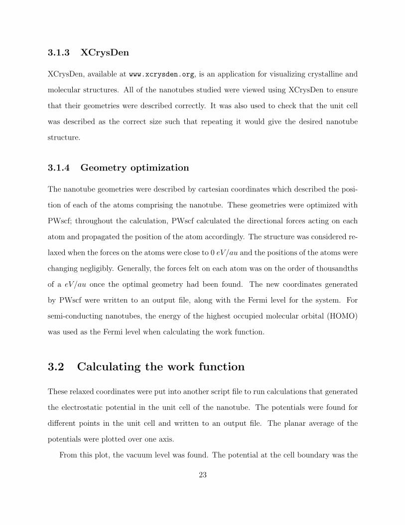
3.1.3 XCrysDen
XCrysDen, available at www.xcrysden.org, is an application for visualizing crystalline and
molecular structures. All of the nanotubes studied were viewed using XCrysDen to ensure
that their geometries were described correctly. It was also used to check that the unit cell
was described as the correct size such that repeating it would give the desired nanotube
structure.
3.1.4 Geometry optimization
The nanotube geometries were described by cartesian coordinates which described the posi-
tion of each of the atoms comprising the nanotube. These geometries were optimized with
PWscf; throughout the calculation, PWscf calculated the directional forces acting on each
atom and propagated the position of the atom accordingly. The structure was considered re-
laxed when the forces on the atoms were close to 0 eV/au and the positions of the atoms were
changing negligibly. Generally, the forces felt on each atom was on the order of thousandths
of a eV/au once the optimal geometry had been found. The new coordinates generated
by PWscf were written to an output file, along with the Fermi level for the system. For
semi-conducting nanotubes, the energy of the highest occupied molecular orbital (HOMO)
was used as the Fermi level when calculating the work function.
3.2 Calculating the work function
These relaxed coordinates were put into another script file to run calculations that generated
the electrostatic potential in the unit cell of the nanotube. The potentials were found for
different points in the unit cell and written to an output file. The planar average of the
potentials were plotted over one axis.
From this plot, the vacuum level was found. The potential at the cell boundary was the
23
Figure 3.9: The process of calculating the work function for a pristine (5,0) CNT. The20-carbon ring was described in the unit cell, and the geometry was optimized. Using theoptimal coordinates, the electrostatic potential in the unit cell was calculated. The two lowerplots show a plot of the potential averaged over the z-axis of the cell. The dark red regionis the vacuum level of the cell. It is possible to see in these plots how the nanotube waspositioned in the unit cell. Projecting this particular 20-carbon ring onto the xy-plane givesa shape of a 10-carbon ring, as seen in the model of the ring in the upper left. The plot inthe upper right shows the potential averaged and projected onto the x-axis. From this plot,the vacuum level was found as the potential value sufficiently far from the nanotube. Thework function was determined by subtracting the Fermi level from the vacuum level.
24
vacuum level used to calculate the work function, and this was the first potential value from
the planar average. Subtracting this vacuum from the fermi level got the work function for
that particular nanotube. Figure 3.9 illustrates the method described above.
After calculating the work function, more calculations were done to create band struc-
tures. The coordinates of the relaxed geometries were put into another shell script that ran
band structure calculations. For all of the band structure calculations for the nanotubes,
100 k -points were used. From these plots, it was possible to see how the band gap of the
nanotube had changed from the functionalizations.
25
Chapter 4
Results and Discussion
4.1 Work functions
The work functions of the nanotubes decreased with functionalization. Table 4.1 summarizes
the work functions calculated in this study, in addition to the Fermi levels and vacuum levels
found. These work functions were calculated by obtaining the Fermi level, or the HOMO
for semi-conducting tubes, from the output files of the relaxation calculations. The vacuum
level was obtained from the plots shown in Figures 4.1 - 4.7, which are the planar average
of the electrostatic potential in the unit cell, plotted as a function of the x-axis of the cell.
The vacuum level was taken as the potential at the cell boundary.
Figure 4.1: Planar average of the electrostatic potential along the x-axis for the pristine (5,0)CNT.
The calculated work functions for the pristine (5,0) and (5,5) SWNTs differed from
values found in previous studies. One possible reason for the discrepancies is the exchange
correlation potential. The generalized gradient approximation (GGA) functional PBE was
used in this study, while in the other studies the local density approximation (LDA) was
used. [9, 10, 18] Also, this study used 12 k -points when performing the calculations, while
other theoretical studies used 30 and 40 k -points. Other than these two factors, it is not
entirely clear why different work functions were found. In both the pristine (5,0) and (5,5)
SWNTs, the work functions found in this study were lower than those found in previous
studies.
The lowering of the work function with the addition of side groups is consistent with
the study done by Suzuki et al. and Zhao et al. where they calculated the work functions
of Cs-intercalated CNTs and bundles. They observed a significant decrease in the work
function with Cs intercalation, which is consistent with the lowering of the work functions
27
Figure 4.2: Planar average of the electrostatic potential along the x-axis for the fully hydro-genated (5,0) CNT.
Figure 4.3: Planar average of the electrostatic potential along the x-axis for the pristine (5,5)CNT.
28
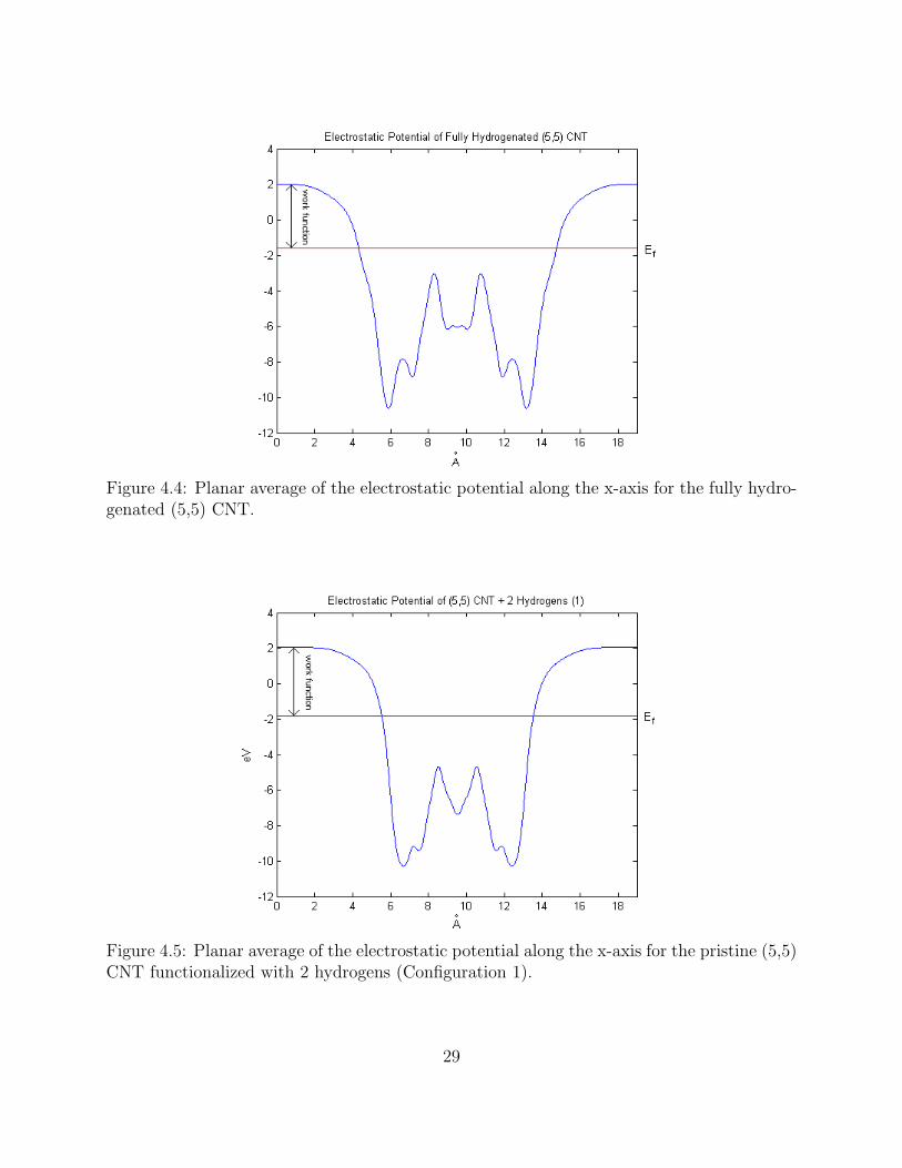
Figure 4.4: Planar average of the electrostatic potential along the x-axis for the fully hydro-genated (5,5) CNT.
Figure 4.5: Planar average of the electrostatic potential along the x-axis for the pristine (5,5)CNT functionalized with 2 hydrogens (Configuration 1).
29
Figure 4.6: Planar average of the electrostatic potential along the x-axis for the pristine (5,5)CNT functionalized with 2 hydrogens (Configuration 2).
Figure 4.7: Planar average of the electrostatic potential along the x-axis for the (5,5) CNTfunctionalized with an aminophenyl group.
30
Figure 4.8: Relaxation of a (5,5) CNT functionalized with 2 hydrogens. The structure wasunstable when the nanotube was defined with only 20 carbons. 60 carbons were necessaryto have an energetically stable structure when functionalizing with two hydrogens.
observed in this study. The study by Zhao et al. also observed a correlation between the
lowering of the work function and concentration of the metal. The more metal that was
intercalated with the nanotube, the lower the work function became. These observations are
also consistent with the results of this study; the nanotubes with greater functionalization
experienced greater lowering of the work function from its pristine counterpart.
The work function of the (5,5) SWNT decreased more dramatically when fully hydro-
genated, than when it was functionalized with just 2 hydrogens. The work functions of the
two configurations of functionalization by 2 hydrogens were different from each other by only
0.02 eV. It appears as though the placement of the hydrogens does not have an effect the
work function, although the concentration of hydrogen does.
31
Figure 4.9: Relaxation of a (5,5) CNT functionalized with 4 hydrogens. The structure wasunstable when the nanotube was defined with only 20 carbons. Relaxing this nanotuberesulted in its splitting.
The instability of smaller nanotubes during hydrogenation discussed in the study by
Zhang et al. was also observed. Smaller nanotubes experience higher curvature and strain,
and the addition of hydrogens can induce cutting of the nanotube. Originally, the nanotubes
functionalized by 2 hydrogens were described by a single ring, or 20 carbons atoms. The
hydrogens caused the nanotube to break open when it was relaxed. The 20 carbon ring
was not stable enough for hydrogenation by 2 hydrogens and the ring opened up, as seen in
Figure 4.8. The ring split in between the two hydrogens, indicating that the (5,5) nanotube
structure with hydrogens along the axis of the tube is not energetically stable. The same
held true with a 20 carbon ring of a (5,5) CNT that was functionalized with 4 hydrogens.
As seen in Figure 4.9, the nanotube broke as it was relaxed. Again, it broke in between the
location of the hydrogens; since such a location exists twice in this structure, the nanotube
32
broke in two places. It is possible that an actual nanotube would have split down its length
due to the high curvature and strain.
The fully hydrogenated (5,0) and (5,5) nanotubes did not break, because the structures
were fully symmetric. All of the bonds are sp3 hybridized in these two SWNTs, and thus
the stresses on the nanotube are uniform. The energetics of these systems did not lead to
cutting of the nanotube. However, it is unclear whether it is possible to fully hydrogenate
such small nanotubes. Experimental results show that nanotubes that are hydrogenated form
atomic coverage of ∼65%. [17] It appears as though nanotubes have not been hydrogenated
100%, such as the ones studied theoretically here. Harsher plasma conditions cannot be
used for hydrogenation, because it may lead to cutting of the nanotube, particularly in small
CNTs. [17] It may not currently be possible to hydrogenate a nanotube with 100% coverage.
4.2 Band structures
The band structures of all the nanotubes were also studied. As expected, the pristine (5,0)
SWNT had no band gap (Figure 4.10). Although a (5,0) SWNT should be semi-conducting
according to the n−m3
rule, the nanotube is actually metallic because of curvature effects. If
a (n,0) CNT has n < 6, that nanotube is metallic. [10] In the band structures of these nan-
otubes, the singly degenerate π band is lowered below the valence band top. This downward
shift of the singly degenerate state is induced by high curvature.
The band structures of interest are the pristine and fully hydrogenated (5,5) SWNTs,
Figure 4.11. The bands cross in the band structure of the pristine (5,5) SWNT, so this nan-
otube is metallic. However, full hydrogenation opened a gap of 2.15 eV in the band structure,
indicating that the nanotube became semi-conducting, or at least, more semi-conducting.
This reduction of metallic nature is consistent with the study by Zhang et al., where they
consistently observed a significant decrease in conduction after H-plasma exposure. The
33
Figure 4.10: Band structure for the pristine (5,0) CNT.
decrease in conductance after hydrogenation can be attributed to the change of hybridized
bonds. CNTs are comprised of sp2 hybridized bonds, which become sp3 when hydrogenated.
This leads to the localization of π-electrons, resulting in decreased conductivity.
The opening of a small band gap of 0.43 eV was also observed in the band structure of
configuration 1 of the (5,5) SWNT functionalized with 2 hydrogens, Figure 4.12. There was
no band gap in configuration 2, but the bands shifted and crossed in a different location
from the pristine nanotube.
Table 4.2: Calculations of Work Functions using Midgap as the Fermi LevelSystem HOMO(eV) LUMO(eV) Midgap(eV) Work Function(eV)fully H SWNT(5,5) -1.7608 0.3920 -1.3688 3.39SWNT(5,5) + 2H (1) -1.9345 -1.8439 -1.8892 3.84
34
Figure 4.11: Band structures for the pristine (5,5) CNT on the left and the fully hydrogenated(5,5) CNT on the right.
Figure 4.12: Band structures for the (5,5) CNT functionalized with 2 hydrogens. Configu-ration 1 on the left, and configuration 2 on the right.
35
For the semi-conducting CNTs, the Fermi level was taken as the energy of the highest
occupied molecular orbital (HOMO). However, some studies have used the midgap level,
calculated from the HOMO and the lowest unoccupied molecular orbital (LUMO), as the
Fermi energy. Table 4.2 shows the work functions for the fully hydrogenated (5,5) SWNT and
configuration 1 of the (5,5) SWNT functionalized with 2 hydrogens, if they were calculated
using the midgap as the Fermi level, instead of the HOMO. There was a decrease in the
work function, because the Fermi level used was higher when taken as the midgap. This
was particularly true for the fully hydrogenated (5,5) SWNT which had a work function of
3.78 eV when using the HOMO as the Fermi level. The value of the work function of semi-
conducting CNTs will be affected by the bandgap if the HOMO is used in its calculation,
especially if this induced band gap is relatively large.
36
Chapter 5
Conclusion
A systematic study of the work functions of differently functionalized SWNTs was conducted.
The work functions decreased with functionalizations. This is seen with the (5,5) SWNT with
an aminophenyl group attached, which had a work function of 3.74 eV. This is in comparison
to the pristine (5,5) SWNT which had a work function of 4.00 eV. The concentration of
hydrogen functionalizing the nanotube affects the work function, while the locations of the
hydrogens do not. With the smaller nanotubes, the high curvature and strain makes them
energetically unstable to hydrogenation.
Functionalizations also affect the band structures of the nanotubes. Hydrogenated nan-
otubes behave more like semi-conducting materials than metallic, due to the localization
of π-electrons. In this study, using the HOMO as the Fermi level in the semi-conducting
nanotubes made the work function higher than when the midgap was used. The size of the
bandgap also played a role in how much the work function was affected by using the HOMO
as the Fermi level.
This work has shown that with functionalization, the electronic structure and properties
of small SWNTs can be tailored. This control over work function in particular could be of
significant importance to the design of electronic devices.
37
Acknowledgments: This study would not have been possible without Professor Nicola Marzari,
Nicholas Miller, and Young-Su Lee with their constant guidance and help. I would also like
to thank the QUASIAMORE research group and the Department of Materials Science and
Engineering at MIT.
38
Bibliography
[1] T. A. Adams, “Physical Properties of Carbon Nanotubes”,www.pa.msu.edu/cmp/csc/ntproperties
[2] L. Forro, et al.,“Electronic and Mechanical Properties of Carbon Nanotubes”’, Proceed-ings of Nanotube, 1999.
[3] R. Gao, Z. Pan, Z. L. Wang, “Work function at the tips of multiwalled carbon nan-otubes”, APL, 2001, 78, 1757-1759.
[4] P. J. F. Harris, “Carbon Nanotubes and Related Structures - New Materials for theTwenty-first Century”, Cambridge University Press, Cambridge, 1999.
[5] P. Hofmann, “Work Function”,whome.phys.au.dk/~philip/q1_05/surflec/node29.html
[6] D. Mayer, “Crystal Structure”,encyclopedia.laborlawtalk.com/Image:Tetragonal.png
[7] Ohio State Univ., “Density Functional Theory”,www.physics.ohio-state.edu/~aulbur/dft.html
[8] Quanum Espresso, www.quantum-espresso.org
[9] B. Shan, K. Cho, “first principles study of work functions of double-wall carbon nan-otubes”, PRL, 2006, 73, 081401.
[10] B. Shan, K. Cho, “First Principles Study of Work Functions of Single Wall CarbonNanotubes”, PRL, 2005, 94, 236602.
[11] M. Shiraishi, M. Ata, “Work function of carbon nanotubes”, Carbon, 2001, 39, 1913-1917.
[12] S. Suzuki, C. Bower, Y. Watanabe, O. Zhou, “Work functions and valence band statesof pristine and Cs-intercalated single-walled arbon nanotube bundles”, APL, 2000, 76,4007-4009.
[13] S. Suzuki, Y. Watanabe, Y. Homma, “Work functions of individual single-walled carbonnanotubes”, APL, 2004, 85, 127-129.
39
[14] E. Thostenson, “Tsu-Wei Chou heads interdisciplinary carbon nan-otube research project”, University of Delaware - UDaily, 2003,www.udel.edu/PR/UDaily/2004/Chou-Atomic-Structureslg.jpg
[15] Yale University, “Electronic and optical properties: carbon nanotubes”,volga.eng.yale.edu/sohrab/grouppage/CNT.html
[16] M. F. Yu, O. Lourie, M. J. Dyer, K. Moloni, T. F. Kelly, R. S. Ruoff, “Strength andBreaking Mechanism of Multiwalled Carbon Nanotubes Under Tensile Load”, Science,2000, 287, 637-640.
[17] G. Zhang, P. Qi, X. Wang, Y. Lu, D. Mann, X. Li, H. Dai, “Hydrogenation and Hy-drocarbonation and Etching of Single-Walled Carbon Nanotubes”, JACS, 2006, 128,6026-6027.
[18] J. Zhao, J. Han, J. P. Lu, “Work functions of pristine and alkali-metal intercalatedcarbon nanotubes and bundles”, PRB, 2002, 65, 193401.


![Double-walled carbon nanotubes: synthesis, structural ...077-088]-01.pdf · Double-walled carbon nanotubes: synthesis, structural characterization, and ... are seamless cylindrical](https://static.documents.pub/doc/80x56/5aa2b5537f8b9ac67a8d717c/double-walled-carbon-nanotubes-synthesis-structural-077-088-01pdfdouble-walled.jpg)


