Work in Progress August 16 , 2017 Reporter: Dave Yotter By: Ben Warner from U.S. Naval Institute August 23, 2017 4:53 PM Image from the Paul Allen-led expedition that found the wreck of USS Indianapolis. The condition of the USS Indianapolis (CA- 35), the World War II-era cruiser preserved for 72 years at the bottom of the sea, has so far proved to be most surprising to researchers studying the wreckage site discovered earlier this week. “The paint is still in place, like on he anchor and on parts of the ship. On the anchor, you can read Norfolk on there. You can read on boxes, on supply boxes, you can read Indianapolis and read very clearly what is on that box,” said Robert Heyland, Underwater Archeology Branch Head with the Naval History and Heritage Command. During Newsletter Volume 44, Number 9, Sept. 2017 Contacts President: Bill Schultheis (714) 366-7602 E-Mail [email protected]Vice President: Mike DiCerbo (714) 523-2518 E-Mail: [email protected]Secretary: Paul Payne (310) 544-1461 Treasurer: Larry Van Es (714) 936-0389 E-Mail: [email protected]Editor, Don Dressel (909) 949-6931 908 W. 22 nd Street Upland, CA 91784-1229 E-mail: [email protected]Web Manager: Doug Tolbert: (949) 644-5416 Web Site www.shipmodelersassociation.org Meeting – Wed., Sept. 20, 7 PM, Red Cross Building, 1207 N. Lemon, Fullerton, CA. 92832 Officers meeting –Wed., Sept. 4, 2017, 7 PM, Graziano’s Pizza, 17487 Imperial Hwy, Yorba Linda 1
Transcript
Work in Progress August 16 , 2017
Reporter: Dave Yotter
By: Ben Warner from U.S. Naval Institute August 23, 2017 4:53 PM
Image from the Paul Allen-led expedition that found the wreck of USS Indianapolis. The condition of the USS Indianapolis (CA-35), the World War II-era cruiser preserved for 72 years at the bottom of the sea, has so far proved to be most surprising to researchers studying the wreckage site discovered earlier this week. “The paint is still in place, like on he anchor and on parts of the ship. On the anchor, you can read Norfolk on there. You can read on boxes, on supply boxes, you can read Indianapolis and read very clearly what is on that box,” said Robert Heyland, Underwater Archeology Branch Head with the Naval History and Heritage Command. During
a Facebook LIVE discussion Wednesday, Heyland and Richard Hulver, a historian with the command, described their research used by billionaire philanthropist and Microsoft co-founder Paul Allen used to find Indianapolis on Saturday. Neyland explained the wreckage, more than 18,000 feet below the sea surface, is resting in a spot protected from currents, at a depth with low oxygen levels and little natural light. “This [was] one of the hardest shipwrecks in the world to find,” he said. But the combination of circumstances making the search so difficult also means the wreckage is well preserved. Metal on the ship, based on the photos Allen’s team has released so far, doesn’t appear to be corroded. “Not much in the way of marine growth,” Neyland said as Allen’s team releases more photos and video, Neyland said there will be more to talk about in terms of the ship’s condition and more about its final moments. Answering a question submitted during the LIVE event, Neyland said the wreckage’s final resting location also helps the long-term preservation of the site. Indianapolis is considered the property of the Navy and is by law considered a protected gravesite. But the extreme depth and rough undersea terrain make it very difficult to visit. Allen’s team is working with the Navy to survey the site, and Neyland said is taking care in a very tough environment to not disturb the wreckage. “This is an incredibly difficult survey, it’s like looking for something on the dark side of the Moon,” Neyland said. Hulver, who is credited with discovering a long-overlooked clue to Indianapolis’ whereabouts, stressed how important it is to not forget the crew and the ship’s illustrious service. Before the war, Indianapolis acted as a flagship for several years, even transporting President Franklin D. Roosevelt to South America as part of his “Good Neighbor” cruise in 1936, according to the NHHC. After the Japanese surprise attack on Pearl Harbor, Indianapolis was one of the first ships to respond, searching for enemy aircraft carriers thought to be nearby. Hulver explained his first knowledge of Indianapolis’ story came through popular culture. “Like many people out there, my initial introduction to the Indianapolis was “Jaws,’” Hulver said. In the movie, fisherman Quint has a monologue detailing spending days in the water after Indianapolis went down, as sailors were attacked by sharks and succumbed to exhaustion. “That was the time I was most frightened, waitin’ for my turn. I’ll never put on a life jacket again,” says the character Quint, played by Robert Shaw in the 1975 film. Hulver said the shark attacks get the most attention, probably because of the film, and are an important part of the story, but exhaustion and dehydration were also major reasons why only 316 of the 800 sailors who entered the water were rescued. But Quint’s line also alludes to one of the lessons learned from the incident. Hulver said the lifejackets used by Indianapolis
2
sailors were only designed to be used for about 48 hours. The sailors were in the water for much longer than that, “and they started to weight the men down.” Both Hulver and Neyland said the real story of Indianapolis is one of courage, both during the war, and after torpedoes from a Japanese submarine sank the ship. For example, Lt. Thomas Michel Conway, ships chaplain, continued tending the men in the water, Hulver said, giving last right to those dying, before he eventually succumbed to exhaustion and drowned. “Indianapolis was one of the most decorated warships of WWII,” Hulver said of the ship which earned 10 battle stars. “This rich history has been overshadowed by its last 15 minutes.”
Winged Monohulls – John Simmons Winged Monohull, with foils and a crew of 2. Scale 5/8 inch to the foot.
John writes: Model shows a slender monohull design of a 22-foot length and 22-inch maximum beam and two supporting outboard foam amas, mounted at the common waterline to stabilize the hull before elevation into the foil position. As the hull speed increases the hull would rise such that only the single foil and the rudder tip planes (2) support the hull at speeds of up to 30 knots. The foils are selected by the fore crewman depending
on the tack chosen by the helmsman. Lowering a foil automatically elevates the adjacent foil with a singular motion. This may be assisted by a bungee elastic system and mating roller mounted between the vertical foils. The horizontal surface of all foils is an airfoil section for lift. The mast is fixed and could be free standing if available. Shrouds and head stay are shown. The jib is conventional and light weight Dacron (of weight similar to a Jenny). The boom uses a rail at the tip but is only required for the minimal outboard movement of the boom underway to adjust the angle of attack of the wingsail. At the vertical hinge, and mounted to the boom of the wingsail, an outhaul allows the helm to adjust the amber underway. This type of rig should never have to run downwind because of the velocity of the wind impacting the sail, either combined or overpowering the existing, and often opposing, wind velocity die to the speed of the vessel.
3
The crew is monomial and the tasks distributed evenly. The fore crew handles the jib furling (if required), the jib sheet on each tack, and the choice of foil and positioning of the same. If required in pre-foil condition, he can counter heel by adding ballast outboard by using the mesh wings and seat on the windward side. The helmsman controls the dual rudders using rudder pedals connected with light weight tubular pushrods such that the rudders work in opposition to minimize the turn radius. He also sets the angle of attack of the boom and adjusts the camber of the wingsail from his seated position. The wing sail shown is of two different designs, both to minimize weight. The forward section is shaped closed cell foam with glass covering, similar to a surfboard. The mast is encapsulated within the leading edge and glassed in this position. No mast rotation is needed or provided for. The shrouds and head stay are mounted at the upper tip leading edge in a single fitting. The aft section shown is Mylar film stretched over a simple rib pattern. This technique could serve both sections. The masting hinge is simply mated eyebolts on a 24-inch spacing and joined with a single 3/8” diameter full length tube that formed the joining hinge line. A single crew configuration has also been designed with a single cockpit and a busy helmsman. Winged Monohull with foils and single crew. Scale 5/8 inch to the foot. Similar to the model described above, this smaller craft is 18-foot long with an overall width of 8 feet 6 inches. The crew is more active than in the above example. Differences are that there is a reduced crew and a simpler sail design. The main and jib are both 1/8-inch-thick ABS or similar to result in a fairly rigid sail that will create its own camber die to its weight. The crew is more active but controls everything without hiking. The amas stabilize the boat until it elevates to the foil position. The foils are dedicated to port and starboard tack and lowering one raises the other. The main sheet (angle of attack control), jib sheet and camber control match the boat as described above. The mast is deck mounted. Rudder controls are pedal activated with push rods. The mast is imbedded in the foam/glass forward wing and the mating hinge is also identical with the two crew boat.
Skipjack Zebulon – Mike Eskew The skipjack is a traditional fishing boat used on Chesapeake Bay for oyster dredging. It is a sailboat which succeeded the bugeye as the chief oystering boat on the bay, and it remains in service due to laws restricting the use of power boats in the Maryland
4
state oyster fishery. The skipjack is sloop-rigged, with a sharply raked mast and extremely long boom (typically the same length as the deck of the boat). The mainsail is ordinarily triangular, though gaff rigged examples were built. The jib is self-tending
and mounted on a bowsprit. This sail plan affords the power needed to pull the dredge, particularly in light winds, while at the same time minimizing the crew required to handle the boat. The hull is wooden and V-shaped, with a hard chine and a square stern. In order to provide a stable platform when dredging, skipjacks have very low freeboard and a wide beam (averaging one third the length on deck). A centerboard is mounted in lieu of a keel. The mast is hewn from a single log,
with two stays on either side, without spreaders; it is stepped towards the bow of the boat, with a small cabin. As typical in regional practice the bow features a curving longhead under the bowsprit, with carved and painted trailboards. A small figurehead is common. A typical skipjack is 40 to 50 feet in length. The boats use direct link Edson worm steering gear mounted immediately forward of the transom. The dredge windlass and its motor are mounted amidships, between the mast and deck house. Rollers and bumpers are mounted on either side of the boat to guide the dredge line and protect the hull. Due to state laws, the boat has no motor (other than for the windless). Most skipjacks were eventually modified with stern davits to hold a dinghy or pushboat to allow motorized travel as permitted by law. (Wikipedia). Mike built this 1:36 scale model of the skipjack Zebulon from a kit and plans purchased at last October’s sale of models. The model features a full suite of sails furled but ready to raise when needed. There is a crew of three aboard. One is at the wheel and two appear to be making the oyster dredge ready for deployment. The davits for the push boat are an interesting timber structure necessary to hang the pushboat clear of the traditional barn door rudder. Most of these were added by the fishermen long after the boat was originally built, hence the homemade appearance.
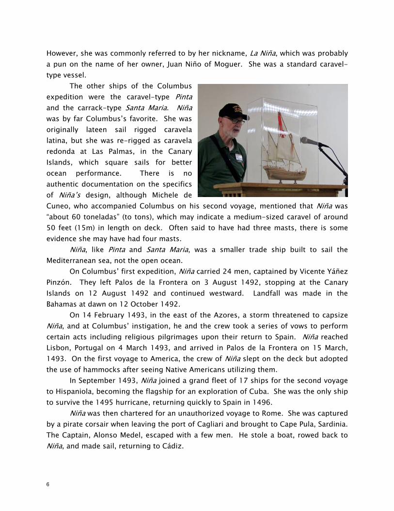
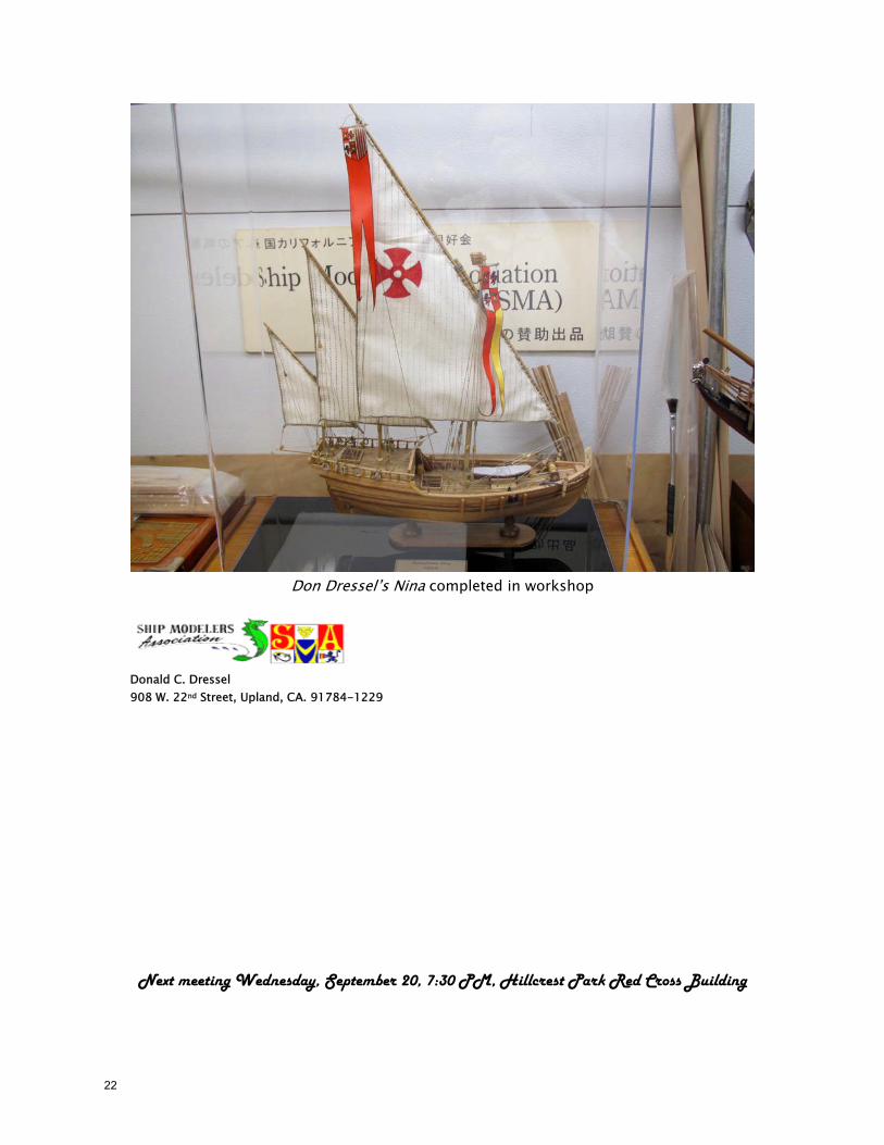
Columbus’ Caravel Nina – Don Dressel La Niña (Spanish for the girl) was one of the three Spanish ships used by Italian explorer Christopher Columbus in hs first voyage to the West Indies in 1492. As a tradition for Spanish ships of the day, she bore a female saint’s name, Santa Clara.
5
However, she was commonly referred to by her nickname, La Niña, which was probably a pun on the name of her owner, Juan Niño of Moguer. She was a standard caravel-type vessel. The other ships of the Columbus expedition were the caravel-type Pinta and the carrack-type Santa Maria. Niña was by far Columbus’s favorite. She was originally lateen sail rigged caravela latina, but she was re-rigged as caravela redonda at Las Palmas, in the Canary Islands, which square sails for better ocean performance. There is no authentic documentation on the specifics of Niña’s design, although Michele de Cuneo, who accompanied Columbus on his second voyage, mentioned that Niña was “about 60 toneladas” (to tons), which may indicate a medium-sized caravel of around 50 feet (15m) in length on deck. Often said to have had three masts, there is some evidence she may have had four masts. Niña, like Pinta and Santa Maria, was a smaller trade ship built to sail the Mediterranean sea, not the open ocean. On Columbus’ first expedition, Niña carried 24 men, captained by Vicente Yáñez Pinzón. They left Palos de la Frontera on 3 August 1492, stopping at the Canary Islands on 12 August 1492 and continued westward. Landfall was made in the Bahamas at dawn on 12 October 1492. On 14 February 1493, in the east of the Azores, a storm threatened to capsize Niña, and at Columbus’ instigation, he and the crew took a series of vows to perform certain acts including religious pilgrimages upon their return to Spain. Niña reached Lisbon, Portugal on 4 March 1493, and arrived in Palos de la Frontera on 15 March, 1493. On the first voyage to America, the crew of Niña slept on the deck but adopted the use of hammocks after seeing Native Americans utilizing them. In September 1493, Niña joined a grand fleet of 17 ships for the second voyage to Hispaniola, becoming the flagship for an exploration of Cuba. She was the only ship to survive the 1495 hurricane, returning quickly to Spain in 1496. Niña was then chartered for an unauthorized voyage to Rome. She was captured by a pirate corsair when leaving the port of Cagliari and brought to Cape Pula, Sardinia. The Captain, Alonso Medel, escaped with a few men. He stole a boat, rowed back to Niña, and made sail, returning to Cádiz.
6
In 1498, she returned to Hispaniola as advance guard of Columbus’ Third Voyage. She was laying in wait at Santo Domingo in 1500. In 1501, she made a trading voyage to the Pearl Coast on the Island of Cubagua, Venezuela, and no further log of her is found in historic archives. (Wikipedia). Don brought in his completed 1:65 scale model of the Niña based on the Amati kit, the construction of which has been discussed in the Mayflower Group meeting in past issues of the SMA Newsletter. The plexiglass case was also shown with the black plexiglass base, both made by PlexiDisplays of La Habra (www.PlexiDisplays.com). The masting and rigging is scratch, since the plans were totally inadequate. It is interesting to note that the replica built in Spain is square rigged, although she was originally rigged lateen.
USS Constitution – Paul Payne
Paul is continuing construction of his scratch built 1:96 scale model of Constitution in her as-built configuration, ca. 1805. Paul has been doing a lot of reworking of the spar deck, bulwarks, stern and head details to conform to the best available research of Constitutions appearance from launch to 1903. Main source has been Karl Marquardt’s Anatomy of the Ship monograph. A second source was the book written by
William Bass titled The Constitution, Super Frigate of many Faces, a limited edition published in 1981. One research source, a painting by Corné shows “mysterious” squares along the side of the ship and one speculation was that these were tie rod ends to help keep the ship from spreading. This lead to further research and Paul’s contacting Margarita Desy, Historian, Naval History and Heritage Command Detachment, Boston at the suggestion of Byrne McLeod, Hon. Secretary of The Society for Nautical Research. Ms. Desy turned up an 1858 photograph of Constitution at Portsmouth which shows the presumed tie rods clearly and additionally that there appear to be air ports cut into the side of the ship for ventilation of the berth deck. One assumption is that the tie rods may have been added at a later rebuild. Deadeyes and chains have been a problem and after trying several sources, Paul found that deadeyes and blocks from Syren Ship Model Co. were the right size. The blocks and deadeyes will be treated to further processing using a block tumbler from
7
Model Shipways. This is a small round box that you assemble with abrasive sheets inside and then activate with a drill motor. Strops and chains came from a photoetch sheet for the 1:100 scale of HMS Victory by Daniel Fisher. Additional items that may be of use from this photoetch are hammock irons and binnacle parts.
HM Cutter Lady Nelson – Brian Stein The cutter Lady Nelson is modeled on a typical British cutter of the late Eighteenth century. The cutter is a native British design and was originally developed by the smugglers of Folkston and surrounding areas. It didn’t take long for the Navy to appreciate the merits of the cutter’s design and they were widely used from the mid-eighteenth century, precisely to counter smuggling. The cutter was designed for speed, adopting an unusually large spread of sail for the size of vessel, deploying both fore and aft and square sails on as single mast. Cutters excelled at patrol and dispatch duties due to their speed; however, they were not suitable for close inshore work due to their deep draught. The original vessel was 52’6” long at the keel, 17’s6” wide, weighed about 60 tons and carried a compliment of about 30 officers and men. Her armament was 10 X 3 pounder carriage guns and 12 X swivel guns on her bulwarks. (Amati). Brian brought in his Lady Nelson model made from an Amati plank-on-bulkhead kit at a scale of 1:64. He said that the kit took about three months to complete and that this was the second model that he has built. The level of difficulty, described as a level two seemed about right and he found the ratlines were easy to put on the shrouds.
HM Armed Vessel Bounty – Brian Stein HMS Bounty, also known as HM Armed Vessel Bounty, was a small merchant vessel purchased by the Royal Navy for a botanical mission. The ship was sent to the Pacific Ocean under the command William Bligh to acquire breadfruit plants and transport them to British possessions in the West Indies. That mission was never completed due
8
to a mutiny led by Acting Lieutenant Fletcher Christian. This incident is now popularly known as the Mutiny on the Bounty. The ship was later burned on Pitcairn Island by the mutineers. The remains of the Bounty were rediscovered in 1957 by an American adventurer and various parts of it have been salvaged since then. Bounty was originally known as collier Bethia, built in 1784 at the Blaydes shipyard in Hull, Yorkshire in England. The vessel was purchased by the Royal Navy for £1,950 on 23 May 1787, refit, and renamed Bounty. The ship was relatively small at 215 tons, but had three masts and was full-rigged. After conversion for the breadfruit expedition, she was equipped with four 4-pounder guns and ten swivels. (Wikipedia)
Brian is just getting started on his 1:60 scale model of Bounty (see photo above) and is again working from an Amati kit. The plank-on-bulkhead framing has been attached to the keel piece and the decking has been put in place for a trail fitting. The kit appears to be a nice one with lots of laser cut wood parts and some photoetch but Brain is finding the instructions to be a bit iffy.
HMS Pegasus – Don Leyman The Swan-class sloops were built as a 14-gun class of ship-sloops for the Royal Navy, although two extra guns were added soon after completion. Surveyor of the Navy, John Williams, designed the class and two vessels to this design (Swan and Kingfisher) were ordered in January 1766. Twenty-three more were ordered to the same design between 1773 and 1779; they formed the ‘standard’ ship sloop design of the British Navy during
the American Revolutionary War, during which eleven of them were lost. Surviving vessels went on to serve during the French Revolutionary War and Napoleonic War. The design provided for 16 gun ports (8 per side, excluding the bridle-ports) but one pair was initially left unoccupied, and the ships were always rated at 14 guns. However, an eighth pair of guns was added from 1780 onwards to utilize the vacant ports, without any change in the nominal rating. The Swan-class sloops were unusually attractive for the type of vessel. Not only did they have sleek hull lines but they also carried an unusual amount of decoration for their size. They were built just before the Admiralty issued orders that all vessels (especially lesser rates and unrated
9
vessels) should have minimal decoration and carvings to save on costs, due to the seemingly ever-continuing war with France and other nations. Don is building his scratch built Pegasus in 1:48 scale using the Antscherl-Herbert books on the Swan-Class Sloops and plans from the National Maritime Museum on Pegasus herself. Several plan versions were available and he chose to use the one with the most available decoration detail. He is using wood purchased from Hobby Mill and has used boxwood for the frames, alder planking and holly for the deck planking. The rails and gratings are walnut. The main deck is complete as it stands now, leaving it half un-planked to allow viewing of below deck details and the main deck framing. The guns are completed and installed as is the foredeck, quarterdeck, gangways, channels, chains, deadeyes and molding. All furniture in the head area of the ship is complete except for the figurehead. Stern and quarter gallery carvings appear complete and this was one of the reasons Don chose Pegasus as his pick of the Swan-Class sloops as details of ship’s carvings were included in the National Maritime Museum’s draughts. There are no cleats for tying off running rigging lines, instead the deck rail posts have provisions for shaves in them so that lines from aloft will run through these sheaves and tie off on the top rail. A jewelry making class helped to build soldering skills which paid off in assembling and finishing the galley stove and stack. There was some discussion about the anchor fish davit, how long and where it would be stowed and then rigged in place for use. This is an important item for a ship handling evolution that is not often discussed. Hammock irons and netting need to be assembled and some appropriate netting material was found at Joanne’s. Don said that he is still uncomfortable with the use of tiller steering on a ship of this size. The rigging decision is yet to be made and he does have spar plans for use if needed.
10
Don Dressel’s Niña
Don Leyman’s HMS Pegasus
Paul Payne’s USS Constitution
11
Brian Stein’s HM Cutter Lady Nelson and his HM Armed Vessel Bounty
Skipjack Zebulon – Mike Eskew
John Simmon’s Winged Monohulls
12
By Don Dressel
Old Salts in Port: John Bakker, Don Leyman, Don Dressel, Steve Jones, John Vanderneut, Ed Fisher.
Ships in Port: Derfflinger, HMS Pegasus, HMS Vanguard, Washington Galley, Sovereign of the Seas.
Don Dressel began the official meeting (there is a lot of camaraderie and discussion before the meeting amongst the “crew”) by discussing the small progress that has been completed on the Derfflinger, a Brandenburg Fluit built by the Dutch. John Bakker built the hull, which was an old Art Am Fusta kit and Don is now masting and rigging the model and will probably put a few sails on her also. The masts and yards have to be scratch built, since a lot of the masting and rigging material supplied with
the original kit is missing, but there are a few drawings and a lot of masting items left from the kit, which makes things a little easier. No line is available, so Don will have to use his “stash” to supply the various sizes of line required for the rigging. Sheaves have been installed in the caps atop the fore and main masts and the tops are being worked on now. Apparently, the rigging instructions which came with the kit are very good (at least the drawings – no written instructions). We will see how things progress as work proceeds.
Don Leyman was the next presenter, who discussed his progress on his scratch built HMS Pegasus. He explained his method of making the railings on the quarterdeck and other areas using boxwood, laminating two thin pieces together and how he turned the balusters for the railings, using needle files on the lathe. The quarterdeck and stern carvings were discussed and the “lights” are left open. Don indicated that he uses Deft spray every time he completes something, so there are a few “coats” of deft on the model.
There was a further discussion on the methods Don used to make the grating which was part of the “opening” for the “Charlie Noble”, or cook stove exhaust. Silver solder was used to
13
make the “stove exhaust pipe” at an angle – there was even a “flap” that went over the opening of the pipe, which Don did not install. The grating around the pipe was very difficult to complete. There was also a long discussion about fish davits, there purpose and just how they were installed and used. Some of this is difficult to explain and is easier with pictures, so below is both a picture of Don’s progress and the stove exhaust – it does swivel and is lined up the correct way.
Ed Fisher discussed his progress on his Sergal kit model of the Sovereign of the Seas and gained a lot of “tips” on how to proceed from the group. He is doing a really good job on the model and indicated that he has been doing a lot of planking and sanding. The “ports” for the guns are already installed prior to installation of the first layer of planking, so they are all located. Ed was introduced to the height gage and the use of proportional dividers to assist him with his
second layer of planking. Don Dressel indicated that he drew all the frames (for the real ship) on the first layer of planking to locate the proper locations of the second layer of planks and the dowel pattern. Ed did indicate that he uses hot water and Downey water softener to help bend the planks to their proper shape. If planks are installed wet, they are allowed to dry completely before gluing them in place.
John Bakker showed the progress he is making on his Amati kit of the HMS Vanguard, with the planking completed and some of the fittings such as the gratings and head work done but not yet installed on the model. The next step is to install the forecastle, quarterdeck and
14
poop decks to the model. The photo shown here shows the interior bulkheads painted red and the internal aspects of the gunports are completed. John is having some problems with the
numbering of parts in the kit instructions – some are not correct and he is finding a lot of help with the builds of this model shown on the Internet. John is still contemplating if he is going to copper plate the lower hull or not – it is not something he is looking forward to. John is a great building of models, however, and we will see how he progresses on all these issues in the coming months.
John also discussed briefly his progress on the model of the Washington Galley, which he is
also working on. This is real slow progress, as all the oars for the model have to be made and it is not one of John’s favorite things to do. John has a LOT of oars to make, not only for this model but for others as well.
As usual, there were a lot of great models shown at this meeting of the Mayflower Group session and I think all of us went away with having learned something new to help us with our modeling endeavors. Another great and fun meeting with lots of cookies and coffee.
15
The ROPE Tokyo Honorary SMA Members – Part VII
By Don Dressel
Mr. Etsuro Tsuboi
One of the pleasures of ship modeling is that you are privileged to meet ship modelers from all over the world and become good friends with them. One of them is Mr. Tsuboi, who was born in December 1929 and is now 87 years young. He is the oldest member of the ROPE, but they all insist that he looks very young. When the SMA visited the ROPE Mr. Tsuboi looked like he was in his 50’s, which he contributes to the fact that he is small and has a young, boy‐like face. He still does enjoy ship modeling and is fortunate to enjoy good health at his age. He has always been interested in precision machinery and the various mechanisms associated with good machines since his boyhood. He enjoyed building airplanes and gliders up to size of 150 cm by himself (scratch) and also enjoyed assembling and dismantling machines such as clocks. He occasionally was unsuccessful in reassembling something he was working on and was scolded by his parents as a result.
This is a brief synopsis of his childhood.
The next adventure that Mr. Tsuboi became involved with was sailing ship modeling. While working in a displaying industry he was involved in a project for TOMY COMPANY, LTD., a manufacturer and retailer of plastic models and toys in Japan. As a result, TOMY COMPANY, LTD. Presented Mr. Tsuboi with a kit model of the sailing ship Pamir in 1971 when he was 41 years old, which became his first experience in ship modeling (see photo at right). Although a plastic model kit, it was still a difficult job at the time. The model itself is still in Mr. Tsuboi’s home, although it has deteriorated over the 40 years of time since it was built. It is a commemorative item as the first ship model that he ever built. Pamir, a four masted barque, was one of the sailing ships of the German shipping company Ferdinand Laeisz, mainly transporting Chilean nitrate to Europe.
16
The next major event that took place in the life of Mr. Tsuboi was his encounter with wooden sailing ship model kits, which led to the subsequent joining of the ROPE. In a way, it was very similar to the events which took place here in California with the Ship Modelers Association and me. Around 1972, Mr. Tsuboi discovered that the store GINZA ITOYA was selling wooden ship model kits. He was intrigued and decided to visit to visit GINZA ITOYA, meeting Mr. Shiozawa (who was in charge of the shop) who told him all about the features of the wooden ship model kits that were available for sale.. He was interested since the kits contained wooden parts for construction which were very different from the plastic kits and wanted to try building one. At the same time, he met Mr. Okumura at the shop (one of the presidents of the ROPE) along with other ship modeling colleagues. He thus went to the shop frequently and became friends with all the ship model builders that were there.
The experience here in California was much the same. I discovered the SHIP SHOP in Anaheim along with the wonderful sailing ship kits that had actual planks in about 1972. I also met Craig Coleman, the proprietor of the shop along with many ship modeling friends, who used the shop to make their models (there were tools and equipment in the back room and meeting started to happen once a month in the evening).
Mr. Tsuboi purchased the ship model kits at GINZA ITOYA and began modeling in wood, even though they were quite expensive at the time. In 1975, at age 45, Mr. Tsuboi became one of the founding members of the ROPE, which was composed of ship modelers who met at the GINZA ITOYA shop.
In 1975 the first ROPE Exhibition was held at the GINZA ITOYA shop on the seventh floor. There were a total of 75 models on display which generated 8500 visitors to the exhibition. Mr. Tsuboi had three models which he had built in the exhibit, all kit models. The were Lilla Dan (1/50 scale), Indiscreet (1/50 scale) and Norske Love (1/75 scale). One of them is pictured to the right.
This was the first exhibition of wooden ship models in Japan and attracted enthusiastic attention of the media as well as many famous people in Japan. The new ROPE club was delighted to see such a tremendous success of their first exhibition.
Very much like the ROPE, our sister club in Japan, the Ship Modelers Association was formed in 1975 when it was discovered that the SHIP SHOP was going to close. Thus, I also was a founding member of the Ship Modelers Association along with many of my ship modeling friends I had associated with. The general opinion, at the time, was that it was too good a thing to lose. The format still used today was adopted in that we would have a monthly meeting and show and discuss our ship modeling efforts at a third Wednesday meeting every month.
17
Mr. Tsuboi was then propelled into not only scratch building models, but miniature scale models. His extraordinary skill and craftsmanship was demonstrated in his first scratch built model, the Presentation of a Model to Dutch Navy Board, which was based on the oil painting by John Seymour Lucas (see photo to the right). The figures were made at 1/33 scale and the ship model was at 1/1000 scale with its length of 55 mm. This model triggered Mr. Tsuboi to make only miniature ship models thereafter.
Mr. Tsuboi then launched his career in making miniature wooden ship models. From 1979 through 2007 all of his models were built at 1/300 scale and presented at the ROPE Exhibitions as indicated below. He also brought the model of the Halifax to the Western Ship Model Conference and Exhibition (put on by the SMA in California aboard the HMS Queen Mary) in 1994 and the HMS Victory to the WSMC&E in 2004.
The 4th ROPE Exhibition ‐‐‐‐ Netherlands Yacht The 5th ROPE Exhibition‐‐‐‐‐Indiscreet The 7th ROPE Exhibition‐‐‐‐‐La Flore The 9th ROPE Exhibition‐‐‐‐‐Marie Janne The 10th ROPE Exhibition—“Speedy” Naval Cutter The 12th ROPE Exhibition‐‐‐Junk The 15th ROPE Exhibition‐‐‐Le Coureur The 18th ROPE Exhibition‐‐‐Halifax The 27th ROPE Exhibition‐‐‐HMS Victory The 31st ROPE Exhibition‐‐‐Le Renommee The 32nd ROPE Exhibition—the Ships of Columbus There is a break here, a further list shows the models he built and presented after the 33rd ROPE Exhibition, but first he offers a brief side story on making the HMS Victory. In addition, I want to show pictures of his models described above, which will be shown in the same order as the list. The one above is his Netherlands Yacht, the first miniature he displayed at the 4th ROPE Exhibition. It was a real pleasure to visit Mr. Tsuboi’s home on April 17, 2013 with myself, Doug Tolbert, Dave Yotter, Gus Agustin with his wife Barbara, Yas Komorita with his wife Cleo and Michel Mantin, all representing the Ship Modelers Association on our last visit to the ROPE. I wish that the Ship Modelers Association could again visit the ROPE in Tokyo, as we always were royally treated and had a wonderful time while there (the Sake was particularly good!). Perhaps a new
18
generation of SMA ship modelers will augment such a trip and have the privilege of attending the ROPE Exhibition and enjoying the hospitality of our Japanese friends. It has been my experience that ship model builders are much the same the world over. Some of the photo’s ‐‐
As they say, a picture is worth a thousand words. The top picture to the left is the Indiscreet with an additional photo of the Netherlands Yacht, the picture to the right at top is the La Flore. The second row of pictures is of the Speedy Naval Cutter and the Marie Janne. The final photo on this page to the left is the Junk model. Again, all of them are in 1/300 scale thus scratch built. The Netherlands Yacht is pictured on the previous page.
This article will continue next month with more pictures of his models and building
techniques as well as the story of the HMS Victory model.
19
20
Upcoming ship modeling events There are two upcoming events that may be of interest to the SMA membership. First is the NRG Conference, which will be held in Florida this October. There will be more information on this event to follow. Second, there is proposed a ship modeling exhibition and conference in Rochefort, France in 2018. There will be more information on this upcoming event also for those who may be interested. Stay tuned for details. Location for good ship model plexi-glass cases Both Dave Yotter and Don Dressel have been obtaining their model cases from PlexiDisplays at 700 E. Lambert Rd – Ste. J – La Habra, Calif. They can be reached at 1-562-690-7817 or emailed at www.PlexiDispays.com. They make excellent plexi glass cases and can even make the base of your model (in black plastic) if you do not want to go to the trouble of making your base. The prices are very reasonable. You have to give them the Inside dimensions of your case when ordering.. In Dave’s case, he ordered a VERY large one for his Philadelphia, which they cut to order, as Dave made his own case out of wood. Treasurer’s Report Larry Van Es reports that there is $4,302.38 in the SMA account for the end of November. Mike has become the advisor and helper for the new SMA Treasurer, Larry Van Es. Since I have received no input from Larry since November, the above figure is still the last info I have. Web Manager’s Report The Webmaster, Doug Tolbert, has no specific announcement for this month, outside of the fact that the SMA web page is working fine. If there are any comments by the SMA membership, please contact one of the officers (see first page of newsletter). San Diego Ship Modelers Guild For those SMA members who may be interested, the San Diego Ship Modelers Guild now has their meetings on the BERKLEY on the second TUSEDAY of each month, instead of the second Wednesday. Your editor and reporter routinely attend the meeting which is usually very informative and enlightening. Tony Devroude cast figure There have been several requests about the Tony Devroude figure on my Halifax model. It is available from Tony Devroude for only $10.00 if you contact him and order the figure. He also does carvings and other figures if desired. Tony can be contacted at [email protected].
21
Don Dressel’s Nina completed in workshop
Donald C. Dressel 908 W. 22nd Street, Upland, CA. 91784-1229
Next meeting Wednesday, September 20, 7:30 PM, Hillcrest Park Red Cross Building