29
17361 WORK REPORT ON THE KLOTZ LAKE PROPERTY THUNDER BAY MINING DIVISION, ONTARIO FOR BALTIC RESOURCES SUBMITTED BY: S. ANDERSON 42F13SW0019 2.17381 KLOTZ LAKE 010

17361WORK REPORT
ON THE
KLOTZ LAKE PROPERTY
THUNDER BAY MINING DIVISION, ONTARIO
FOR
BALTIC RESOURCES
SUBMITTED BY: S. ANDERSON
42F13SW0019 2.17381 KLOTZ LAKE 010
TABLE OF CONTENTS
INTRODUCTIONLOCATION AND ACCESSCLAIM STATUSPERSONNELPREVIOUS WORKGENERAL GEOLOGYWORK PROGRAM.MAGNETOMETER THEORYVLF-EM THEORYPROJECT RESULTSRECOMMENDATIONS AND CONCLUSIONSCERTIFICATE.
PAGE
l12234455,6778
FIGURES
LOCATION HAP REGIONAL LOCATION HAP CLAIM SKETCH.
FIGURE lFIGURE 2FIGURE 3
LIST OF MAPS
POSTED AND CONTOURED MAGNETOMETERPROFILED VLF-EMCONTOURED FRASER FILTERED VLF-EM.
MAP l,2 MAP 3 MAP 4
42F13SW0019 2.17381 KLOTZ LAKE 010C

INTRODUCTION
The contents of this report will deal with the Geophysical work program carried out by S. Anderson and D. McKinnon on the Klotz Lake Property. This property is located within the Klotz Lake Area (G-295), Thunder Bay Mining Division, District of Geraldton, Ontario (Fig l).
The work program conducted was carried out from April 1/97 to April 10/97 and was supervised by Steve Anderson. It included establishing 40 km of grid lines which was then surveyed with magnetometer and VLF.
The purpose of this exploration project was to survey areas covered by water that cannot be surveyed by a work program planed for the summer months. The area covered by this work program is within a geological trend that is reported to contain anomalous values in gold.
LOCATION AND ACCESS
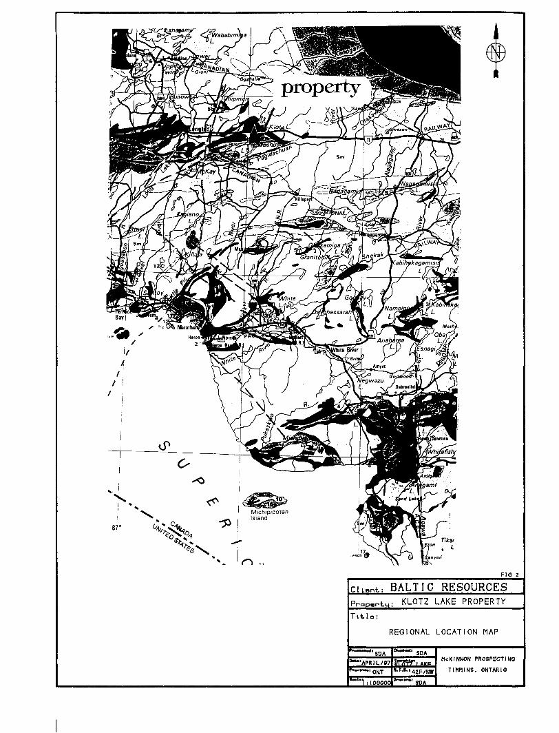
The Klotz Lake Property is located within the Thunder Bay Mining Division District of Geraldton, Ontario. It is situated Just south of the Trans-Canada Hwy and Klotz Lake. In a straight line, the claim block is approximately 40 km East of the town of Lonlac (Fig 2).
Access to the property during the survey period was gained by the Trans-Canada Hwy east from the town of Longlac for approximately 40 km, to Pagwachuan Lake Road. This road heads south from the Hwy and at about the 3 km. point crosses the cental portion of the survey area just west of Adel Lake. This road is no maintained during the winter months. As a result the property was accessed by snowmobile for this portion of the work program.

73
O 30 100 130 nilas
PROVINCE OF ONTAR10
F10 l
Cli.nl; BALTIC RESOURCES
KLOTZ LAKE PROPERTY
Tltla:
LOCATION MAP
SPA"APRIL/97"ONT
a-l 50m l
SPA
P LAKE
42F/NW
SPA
MCKINNON PROSPECTING TIMMINS. ONTARIO
87
F10 2
: BALTfC RESOURCESPro PBriu; KLOTZ LAKE PROPERTY
Title:
REGIONAL LOCATION MAP
SPA
"APRIL/97'OUT
'"lil QOQOO
SOA
l AKP"•'•'•'42F/NW
SPA
MCKINNON PROSPECTi NOTIMMINS. ONTARIO

CLAIM STATUS
The claims over which this project was conducted are part of a large group of Claims that make up the Klotz Lake Property. The following is a list of the claims covered or partially covered by this work program. All the claims covered are within the Thunder Bay Mining Division and can be found on the Klotz Lake Area (G-295) claim map (Fig 3).
CLAIM ft
120160611768861176885117688411768831176881117687911768781176877117687611768751176874117687311768721176871
ft OF UNITS
6l l l l l l l l l l l l l l
PERSONNELThe people who were directly involved in this work program
are listed below:
Steve Anderson Donny McKinnon
Timmins, Ontario Timmins, Ontario
All work was supervised by Steve Anderson.

G-295
FIG
ciiant; BALTIC RESOURCESP™.r-tu! KLOTZ LAKE PROPERTY
Title:
CLAIM SKETCH
SPA•"APRIL/fl?
'ONT
" SDA
SDA
MCKINNON PROSPECTING TIMMINS. ONTARIO
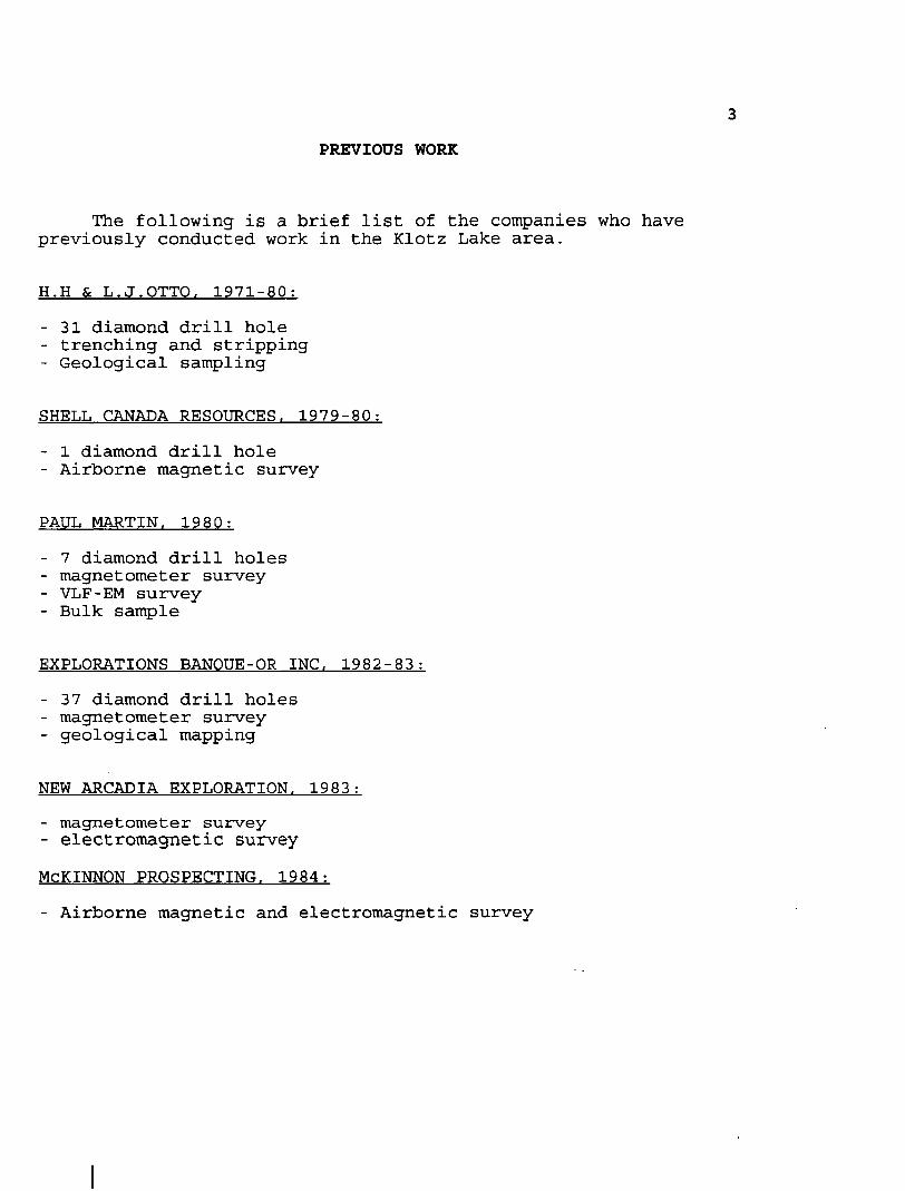
PREVIOUS WORK
The following is a brief list of the companies who have previously conducted work in the Klotz Lake area.
H.H b L.J.OTTO. 1971-80;
- 31 diamond drill hole- trenching and stripping- Geological sampling
SHELL CANADA RESOURCES. 1979-80:
- l diamond drill hole- Airborne magnetic survey
PAUL MARTIN. 1980:
- 7 diamond drill holes- magnetometer survey- VLF-EM survey- Bulk sample
EXPLORATIONS BANOUE-OR INC. 1982-83:
- 37 diamond drill holes- magnetometer survey- geological mapping
NEW ARCADIA EXPLORATION. 1983:
- magnetometer survey- electromagnetic survey
MCKINNON PROSPECTING. 1984:- Airborne magnetic and electromagnetic survey

GENERAL GEOLOGYThe Klotz Lake Property lies within the easternmost part of
the Wabigoon Volcanic Belt of the Archean subprovince of the Canadian Shield.
This belt is characterized by a complex of generally east- west trending Archean Metavolcanics, metasediments and Mafic to Felsic intrusive rocks.
WORK PROGRAM
The work conducted on the Klotz Lake Property was carried out from April 1/97 to April 10/97. This project basically involved three stages. This included establishing a grid that was covered by magnetometer and VLF-EM surveys.
LINE CUTTING
The first part of this project involved establishing a grid over Adel Lake and a small pond to the west. This was set up in order to cover an area of interest that cannot be surveyed during the summer months. A total of 40km. of grid lines were established utilizing cross-lines in a north-south direction, with an east-west base line and tie lines. Lines were cut set-up every 50 meters, with station pickets every 25 meters.
The point in which each line met the shoreline was marked and all pickets were removed from the lake and pond. This provided a grid, from which all the work to be carried out on the property could be tied in to.
GEOPHYSICAL PROGRAM
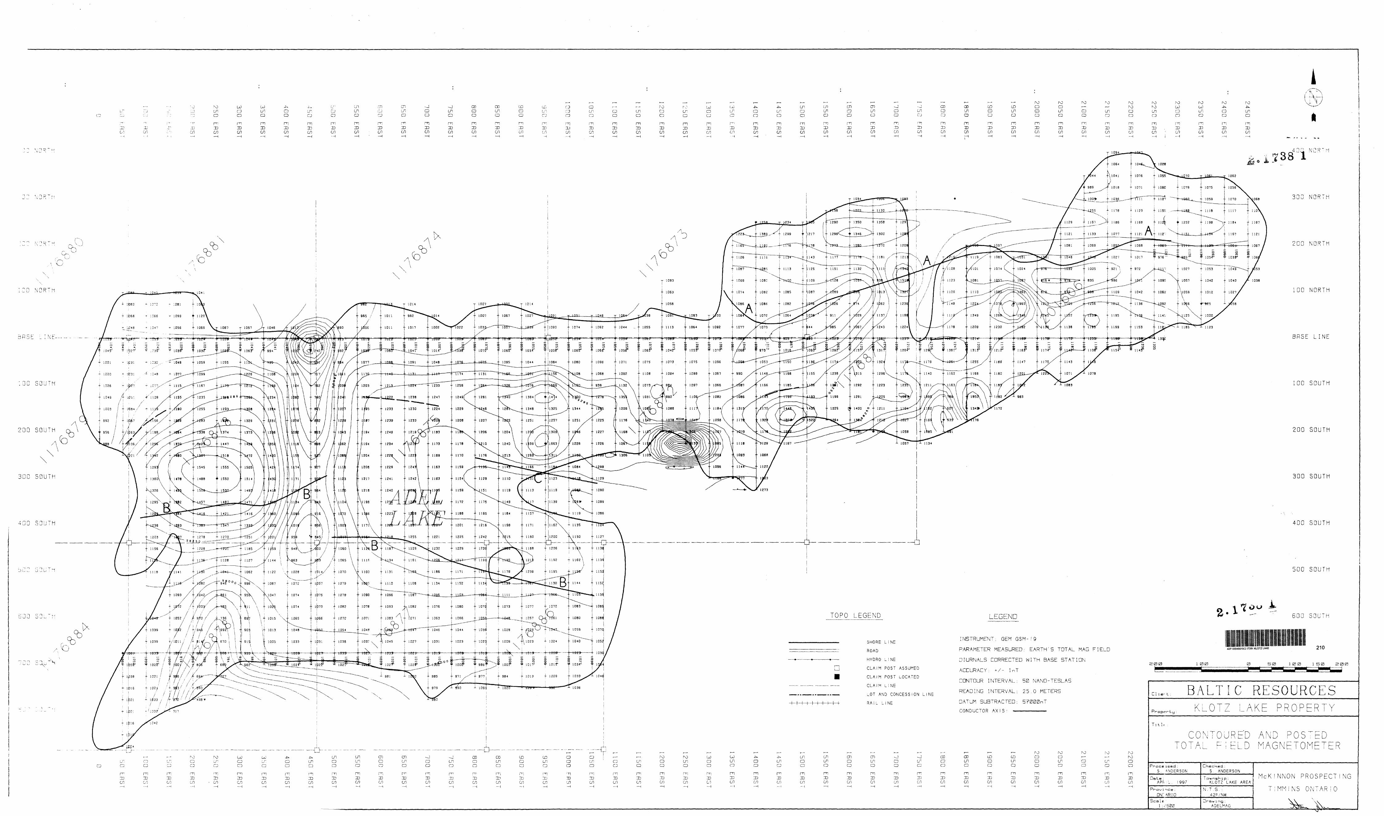
The geophysical part of the project included Magnetometer and VLF-EM surveys. The entire grid was covered with magnetometer, while only that area covered by Adel Lake was surveyed with VLF. The purpose of these surveys was to provide data which might aid in outline the limits of the various geological units that extend across the grid.
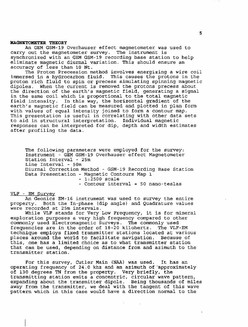
MAGNETOMETER THEORYAn GEM GSM-19 Overhauser effect magnetometer was used to
carry out the magnetometer survey. The instrument is synchronized, with an GEM GSM-19 recording base station to help eliminate magnetic diurnal variation. This should ensure an accuracy of less than 10 Nt.
The Proton Precession method involves energizing a wire coil immersed in a hydrocarbon fluid. This causes the protons in the proton rich fluid to spin or precess simulating spinning magnetic dipoles. When the current is removed the protons precess about the direction of the earth's magnetic field, generating a signal in the same coil which is proportional to the total magnetic field intensity. In this way, the horizontal gradient of the earth's magnetic field can be measured and plotted in plan form with values of equal intensity joined to form a contour map. This presentation is useful in correlating with other data sets to aid in structural interpretation. Individual magnetic responses can be interpreted for dip, depth and width estimates after profiling the data.
The following parameters were employed for the survey:Instrument - GEM GSM-19 Overhauser effect MagnetometerStation Interval - 25mLine Interval - 50mDiurnal Correction Method - GSM-19 Recording Base StationData Presentation - Magnetic Contours Map l
- 1:2500 scale- Contour interval = 50 nano-teslas
VLF - EM SurveyAn Geonics EM-16 instrument was used to survey the entire
property. Both the In-phase (dip angle) and Quadrature values were recorded at 25m intervals.
While VLF stands for Very Low Frequency, it is for mineral exploration purposes a very high frequency compared to other commonly used Electromagnetic Surveys. The commonly used frequencies are in the order of 18-20 kilohertz. The VLF-EM technique employs fixed transmitter stations located at various places around the world to facilitate navigation. Because of this, one has a limited choice as to what transmitter station that can be used, depending on distance from and azimuth to the transmitter station.
For this survey, Cutler Main (NAA) was used. It has an operating frequency of 24.0 khz and an azimuth of "approximately of 130 degrees TN from the property. Very briefly, the transmitting station emits a concentric, circular wave pattern, expanding about the transmitter dipole. Being thousands of miles away from the transmitter, we deal with the tangent of this wave pattern which in this case would have a direction normal to the

azimuth of 130 degrees. Thus any conductors having a general E-W strike direction would be intersected by this signal which induces a signal in the conductor which in turn opposes the primary signal from the transmitter station. This elliptically polarizes the resultant field enabling detection of the conductor using a receiver coil to determine the attitude of the resultant field at various points along the grid lines.
The resultant field dips away from the conductor axis on both sides of the conductor producing a cross-over on the conductor axis. For an E-W conductor, a true cross-over would occur where the field dips south and changes to a north dip as you progress from south to north. For this survey, a +S- system is used where a (H-) dip angle means the field is dipping to the south (indicating anomaly is to north) and a (-) dip angle means the field is dipping to the north (indicating anomaly is to south). This is the case only if all readings were taken facing north as per this survey.
The quadrature values, while not useful alone, can help distinguish between bedrock conductors which generally have a smaller out-of-phase response than overburden or short wavelength conductors. Also, the polarity of the quadrature is diagnostic, ie; if the polarity follows or is the same sense as the In-phase it gives more credibility to the conductor. Reverse quadrature often indicate overburden responses.
The following parameters were employed for the survey:
Instrument - Geonics EM-16Transmitter Station - Cutler Main (USA)
- Call symbol NAA Frequency - 24.0 KHZAzimuth to station - approx. 130 degrees TN Reading Direction - All reading taken facing north Station Interval - 25m Line Interval - 50m Data Presentation - Plan, profiled map No l
- Plan, Fraser Filtered map No l- Scale - 1:2500- profile scale l cm =
PROJECT RESULTS
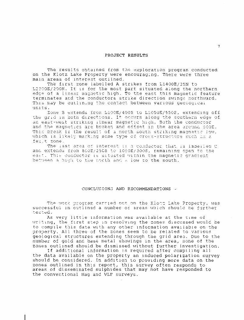
The results obtained from the exploration program conducted on the Klotz Lake Property were encouraging. There were three main areas of interest outlined.
The first zone labelled A strikes from L1400E/25N to L2300E/200N. It is for the most part situated along the northern edge of a linear magnetic high. To the east this magnetic feature terminates and the conductors strike direction swings northward. This may be outlining the contact between various geological units.
Zone B extends from L100E/400S to L1050E/550S, extending off the grid in both directions. It occurs along the southern edge of an east-west striking linear magnetic high. Both the conductor and the magnetics are broken and offset in the area arounc 500E. This break is the result of a north south striking magnetic low, which is likely marking some type of cross-structure such as a f au.t zone.
The last area of interest is a conductor that is labelled C and extends from 8GOE/250S to 1050E/300S, remaining open to the east. This conductor is situated within trie magnetic gradient between a niah to the north and a low to the south.
CONCLUSIONS AND RECOMMENDATIONS
The work program carried out on the Klotz Lake Property, was successful in outlined a number of areas which should be further tested.
As very little information was available at the time of writing, the first step in resolving the zones discussed would be to compile this data with any other information available on the property. All three of the zones seem to be related to various geological structures extending through the grid area. Due to the number of gold and base metal showings in the area, none of the zones outlined should be dismissed without further investigation.
If additional information is required after compiling all the data available on the property an induced polarization survey should be considered. In addition to providing more data on the zones outlined in this report, this survey often responds to areas of disseminated sulphides that may not have responded to the conventional Mag and VLF surveys.

CERTIFICATION
I, Steve Anderson of Timmins, Ontario hereby certify that:
I hold a three year Technologist Diploma from SirSandford Flemming College , Lindsay, Ontario, obtainedin May 1981.I have been practising my profession since 1979 inOntario, Quebec, Nova Scotia, New Brunswick,Newfoundland, NWT, Manitoba, and Saskatchewan.I have been employed directly with Asamera Oil Inc.Urange11schaft Canada Ltd.. Nanisivik Mines Ltd., R.s.Middleton Exploration Services Ltd. f and RayanExploration Ltd.I have based conclusions and recommendations containedin this report on knowledge of the area, my previousexperience and on the results of nine field workconducted on the property during 1997.
ated this iOtn day of April, 1997
at Longi.au:, Ontario.
APPENDIX A
GBM GSM-19 MAGNETOMETER
Page 3
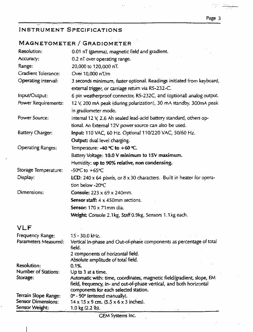
INSTRUMENT SPECIFICATIONS
MAGNETOMETER l GRADIOMETERResolution:Accuracy:Range:Gradient Tolerance:Operating interval:
Input/Output: Power Requirements:
Power Source:
Battery Charger:
Operating Ranges:
Storage Temperature: Display:
Dimensions:
VLFFrequency Range: Parameters Measured:
Resolution: Number of Stations: Storage:
Terrain Slope Range: Sensor Dimensions: Sensor Weight:
0.01 nT (gamma), magnetic field and gradient. 0.2 nT over operating range. 20,000 to 1120,000 nT. Over 10,000 nT/m3 seconds minimum, faster optional. Readings initiated from keyboard, external trigger, or carriage return via RS-232-C. 6 pin weatherproof connector, RS-232C, and (optional) analog output 12V, 200 mA peak (during polarization), 30 mA standby. 300mA peak in gradiometer mode.Internal 12V, 2.6 Ah sealed lead-acid battery standard, others op tional. An External 12V power source can also be used. Input: 110 VAC, 60 Hz. Optional 110/220 VAC, 50/60 Hz. Output: dual level charging. Temperature: -40 ''C to *60 "C Battery Voltage: 10.0 V minimum to 15V maximum. Humidity: up to 90^ relative, non condensing. -500C to -l-65 0C
LCD: 240 x 64 pixels, or 8 x 30 characters. Built in heater for opera tion below -20"C Console: 223 x 69 x 240mm. Sensor staff: 4 x 450mm sections. Sensor: 170 x 71 mm dia. Weight: Console 2.1 kg, Staff 0.9kg, Sensors 1.1 kg each.
15-30.0 kHz.Vertical In-phase and Out-of-phase components as percentage of totalfield.2 components of horizontal field.Absolute amplitude of total field.0.1 ro.Up to 3 at a time.Automatic with: time, coordinates, magnetic field/gradient, slope, EMfield, frequency, in- and out-of-phase vertical, and both horizontalcomponents for each selected station.O0 - 900 (entered manually).14 x 15 x 9 cm. (5.5 x 6 x 3 inches).1.0 kg (2.2 Ib). ^^
GEM Systems Inc.

APPENDIX B
GEOMETRICS EM-16, VLF-EM

(rLAIMt WAVt; tM INSlKUMblMIS-
VLF EM
EMI6One of the most popular and widely used electromagnetic Instruments, the EM! 6 VLF receiver makes Ilw ideal reconnaissance EM. This can be attributed to its field reliability, operational simplicity, compactness and mutual compatibility with other reconnaissance instruments such as portable magnetometers and radiometric detec tors.
The VLF method of EM surveying, pioneered by Geonics, has proven to be a simple economical means of mapping geological structure and fault tracing. The applications are many and varied, ranging from direct detection ol massive sulphide conductors to the indirect detection ol precious metals and radioactive deposits.
FEATURES•The EM16 is the only VLF instrument that measures the quad-phase as well as
the in-phase secondary field. This has the advantage ol providing an additional piece of data lor a more comprehensive interpretation and also allows a more accurate determination ol the tilt angle.
•The secondary fields are measured as a ratio to the primary field making the measurement independent of absolute field strength.
•The EM16 is the only VLF receiver that can be adapted to measure VLF resistivity.
SpecificationsMEASURED QUANTITY In phase and quad-phase components of vertical mag
netic liek) as a percentage of horizontal primary field, (i.e. tangent of the tilt angle and ellipticity)
SENSITIVITY In phase :±150V. Quad phase :± 40V.
RESOLUTION ±1V.OUTPUT Nulling by audio tone. In phase indication from mechan
ical Inclinometer and quad-phase Irom a graduated dial.OPERATING FREQUENCY 15-25 kHz VLF Radio Band. Station selection dona by
means ol plug-In units.OPERATOR CONTROLS On/Off switch, battery test push button, station selector
switch, audio volume control, quadrature dial, inclino meter.
POWER SUPPLYDIMENSIONS WEIGHT
6 disposable'AA'cells 42 x 14 x 9 cm Instrument: 1.6 kg Shipping : 5.5 kg
VLF RESISTIVITY METER
EMI6/I6RThe EM16R is a simple, button on attachment to the EM 16 converting it to a direct reading terrain resistivity meter. The EM1ER interfaces a pair of poten tial electrodes to the EM 16 enabling the measurement of the ratio of. and the phase angle between, the horizontal electric and magnetic fields of the plane wave propagated by distant VLF radio transmitters.
The EM16R is direct reading in ohm-meters of apparent ground resistivity. If the phase angle is 45", the resistivity reading is the true value and the earth is uniform to the depth of exploration (i.e. a skin depth). Any departure Irom 45" of phase in dicates a layered earth. Two layer interpretation curves are supplied with each in strument to permit an interpretation based on a two layer earth model.
This highly portable resistivity meter makes an ideal tool for quick geological map ping and has been used successfully lor a variety ol applications.
•Detection ol massive and disseminated sulphide deposits•Overburden conductivity and thickness measurements• Permalrosl mapping• Detection and delineation ol industrial mineral deposits• Aquifer mapping
EMIBR ATTACHMENT
MEASURED QUANTITY
RESISTIVITY RANGES
PHASE RANGE
RESOLUTION
OUTPUT
OPERATING FREQUENCY
INTERPR08E SPACING
PROBE INPUT IMPEDANCE DIMENSIONS
WEIGHT
•Apparent Resistivity of the ground in ohm-meters•Phase angle between Ex and Hy in degrees• 10- 300 onm-meters• 100- 3000 ohm-meters• 1000 - 30000 ohm-meters0-90 degrees• Resistivity :±2V. full scale• Phase :±0.5*Null by audio tone. Resistivity and phase angle read fromgraduated dials.15-25 kHz VLF Radio Band. Station selection by meansol rotary switch.10 meters100 MO In parallel with 0:5 picofarads19 x 11.5 x 10 cm.(attached to side of EM16)1.5 kg (including probes and cable)
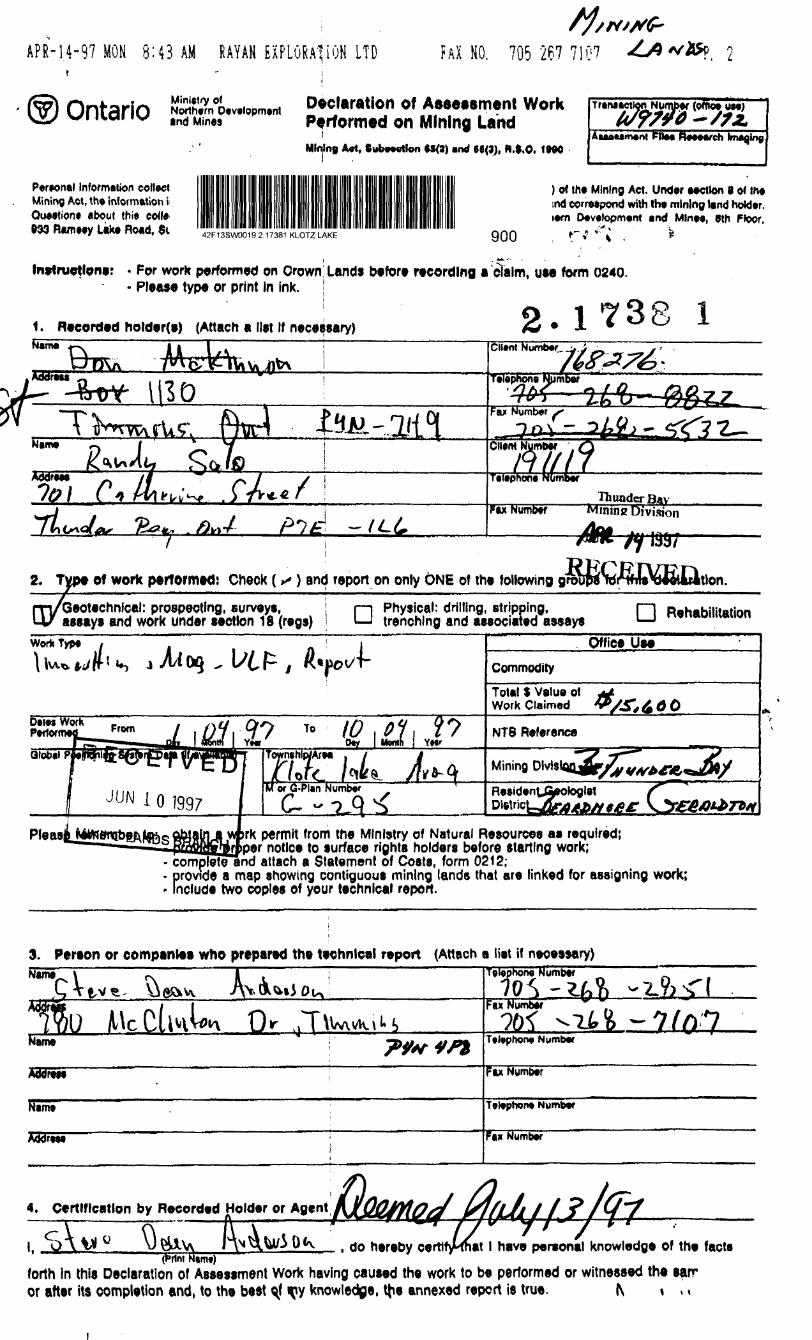
APR-14-97 MON 8:43 AM RAYAN EXPLORATION LTD?
Ontario
FAX NO. 705 267 710?
ind Mines^claratlon of Assessment Work Performed on Mining LandMining Art, Subnotion *S(a) and (6(3), N.S.O. l WO
(office
AuM*m*ni FM** Reeeesch
Perwnal Information collect Mining Act, t h* information i QuMtion* about this coll* 999 Rwntey Like Rond, Si
) of m* Mining Act. Under Motion s ofln* ind correjpond with Iht mining land hokfor. i*m D*v*topm*nt tnd Mint*, Oth Floor,
42F13SW0019 2.17381 KLOTZ LAKE 900
Inttruetlone: - For work performed on Crown; Lands before recording a cTalm, use form 0240. - Please type or print In ink. '
1. Recorded holder(e) (Attach a list If necessary) 2. 1738 l
p*x Numoer minine Division
2. Typ* of work performed! Chock ( s ) and report on only ONE of the followingm/Geotechnical: prospecting, surveys, j i—i Physical: drilling, stripping, l—l p.hahiiitaiinn U/ assays and work under section 18 (regs) l l—l trenching and associated a***"* '—l "*n*DHIM"lonassaysWork Type
Detes Work
Office UseCommodityTote.1 S Valua of Work Claimed ^ g OTO io
Yt* 0^ l Mornh j YH'NTS Reference
JUN l Q 1997lor G.PI*n
ArM . 7 yi /cite, /lv*-—————*~*
Mining Dlvls
rk permit from the Ministry of Natural Resources as required; __j per notice to surface rights holders before starting work;
- complete and attach a Statement of Costs, form 0212;- provide a map showing contiguous mining lands that are linked for assigning work;- Include two copies of your technical report.
3. Pereon or companies who prepared the technical report (Attach a Net if necessary)teio )hong NumberName
u
ZbFax Number a
Rime Telephone Number
Fax NumberXTOrtir
Nimt Telephone Number
FM Number
4. Certification by Recorded Holder or Agent
(Printl have personal knowledge of the facts
forth in this Declaration of Assessment Work having caused the work to be performed or witnessed the san er after its completion and, to the best qf q?V knowledge, the annexed report is true. (\ \ , ,

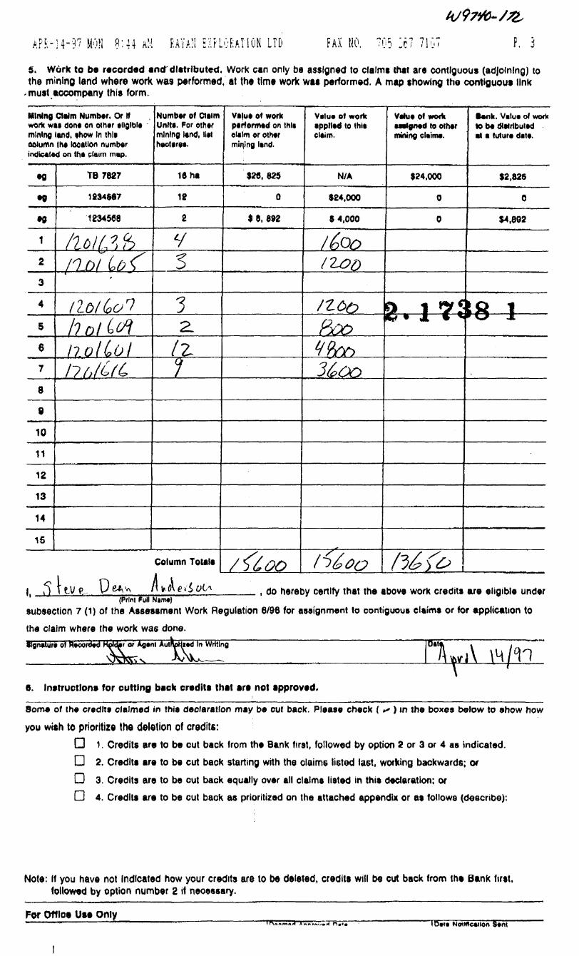
AFM4-97 MON 8:44 AM RAYAN EXPLORATION LTD FAX NO, 705 26; 7107 p. jS. Work to b* recorded and'diatributed. Work can only be assigned to claims that are contiguous (adjoining) to the mining land where work was performed, at the time work waa performed. A map showing the contiguou* link
'must accompany this form. l
Mining Claim Numb*. Or If work WM dons on othor tllglblo mining land, show In (Mi ookMin (h* tooalton numbtr indicated cm tht chum map.
Number of Claim Units, for oft* mining land, M Kootgros.
valu* of work porformod on thli claim or othor mifing land.
Velu* of work •ppllad to thl* claim.
Valua of work aaal0n*d to othor mining claim*.
••nfc. Valuo of work to bo dtttrlbuttd at a futura data.
TB7827 16 ha , 625 N/A 624,000 52,825
12S4M7 18 624,000
•0 1234540 16.892 64,000
*TT64,8923s-f
Ztoof 7 f
/ntfiftf
?ye
S*
10 int1112
13
*14 in15
Column Totals
l, , do hereby certify that the above work credits are eligible under(Print Full Nanw)
subsection 7 (1) of the Assessment Work Regulation 6/96 for assignment to contiguous claims or for application tothe claim where the work was done.Signature of hvccnfed Holdar or
e. Instruction* for cutting back credit* that are not approved.
Some of the credit* claimed in thi* declaration may be cut back. Pleaae check ( f ) in the boxes below to enow howyou wish to prioritize the deletion of credits: l
D 1, Credits are to be cut back from the Bank first, followed by option 2 or 3 or 4 as indicated. O 2. Credits are to be cut back starting with the claims listed last, working backwards; or O 3. Credits are to be cut back equally over all claims listed in this declaration; or Q 4. Credits are to be cut back as prioritized on the attached appendix or as follows (describe):
Note: If you have not Indicated how your credits are to be deleted, credits will be cut back from the Bank first, followed by option number 2 if necessary.
Fer Off lot Use Only______ ,——.————^_________________ ______R*CfIVtd 8Ump ~~"*"————————; [bwnad Aapfovad Oat* ! (Data Notification Sam
APR-14-97 MON 8:44 M RAYA'l E'FLGfcATION LTD FAX HO. P. 3
S. Work to be recorded and~ distributed. Work can only be assigned to claims that are contiguous (adjoining) to the mining land where work was performed, at the time work was performed, A map showing the contiguous link
. must accompany this form.
Mining Claim Number. Or If work wti don* on other eligible mining lend, enow In this ooiumn the location number indicated on the claim map.
eg
•B
e0
1
2
3
4
5
6
7
8
e10
1112
13
14
15
TB7627
1234687
1234568
/lcltftiPol (,of
tloKooihnlWliolLolnd&fc,
Number of Claim Unit*. For other mining land, liet heotws.
16 ha
18
2
yS1•z.
fc1
Column Totala
velue of work performed on thlt claim or other mining land.
128, 625
0
* 6, 692
/&00
Velu* ol work applied to thii claim.
N/A
124,000
6 4,000
/6oo12&D
nc*o&KV9m3^oo
tf 600
Vehie pi wo* asalgned to other mining claim*.
*24,000
0
0
CI 1 *yf (g* 1 C *
fi^fc
tank. Value of work K5 be distributed •t t tutor* dal*.
S 2, 825
0
(4,692
58 1* \J JL
l, s , do hereby certify that the above work credits are eligible under(Print Full Nam*)
subsection 7 (1) of the Assessment Work Regulation 6/96 for assignment to contiguous claims or for application to the claim where the work was done.Signature o)
e. Instructions for cutting back credits that are not approved.
Some of the credits claimed in this declaration may be cut back. Please check (*- ) m the boxes below to ehow how
you wich to prioritize the deletion of credits:D 1. Credits are to be cut back from the Bank first, followed by option 2 or 3 or 4 as indicated. D 2, Credits are to be cut back starting with the claims listed last, working backwards; or D 3. Credits are to be cut back equally over all claims listed in this declaration; or D 4. Credits are to be cut back as prioritized on the attached appendix or as follows (describe):
Note: If you have not Indicated how your credits are to be deleted, credits will be cut back from the Bank first, followed by option number 2 if neoessary.
For Office Use OnlyID** Notification Sent
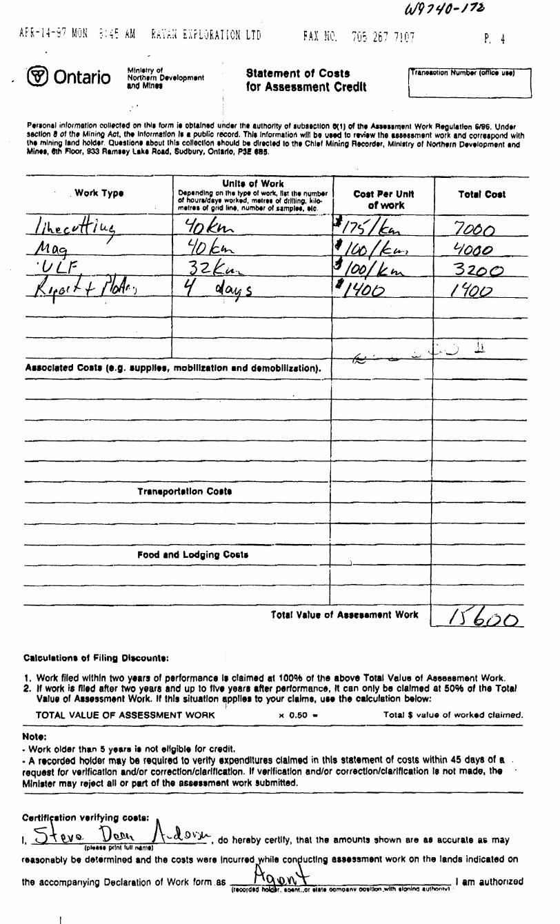
APR-14-97 MON RAVr.ii E:\FLORATION LTD FAX HO. 705 267 7107 P. 4
of Northern Development Statement of Costs
for Assessment Credit[Tranwwtion Number (office use)
Personal information collected on thii form ia obtained under the authority of subsection 9(1) of the Aawisment Work Regulation 6/96. Under section 0 of the Mining Act. the information la a public record. Thle Information will be uaed to review the assessment work and correspond with the mining land holder Questions about this collection should be directed to the Chief Mining Recorder, MInlttry of Northern Development and Mine*, 9th Floor, 933 Ramsay Lake Road, Sudbury, Ontario, P3E 985.
Work Type
//UtWfvVMac}'ULF
/6,^/f /y* -j'
Units of WorkDepending on the type of work, list the number of hours/days worked, metres of drilling, kilo metres of grid line, number of camples, etc
Hofa^LlDlc^32^-,
H pfefcs— i ———— 7 * —————————
Associated Costs (e.g. supplies, mobilization and demobilization).
Transportation Costs
Food and Lodging Costa
Cost Per Unit of work
rW/k.t/to/t*.t/od/k^'wot?
—— fe-*- — *** — ̂ -^f/^**
t-
Total Value of Assessment Work
Total Cost
7^0
^oao'Szoo/foe
'} Ji ^•*- ***r^ ***"
/f tanCalculations of Filing Dlecounts:
1. Work filed within two years of performance Is claimed at 100QX) of the above Total Value of Assessment Work.2. If work is filed after two years and up to five years after performance, It can only be claimed at 5036 of the Total
Value of Assessment Work. If this situation applies to your claims, use the calculation below:TOTAL VALUE OF ASSESSMENT WORK x 0.50 - Total t value of worked claimed.
Note:- Work older than 5 years is not eligible for credit.- A recorded holder may be required to verify expenditures claimed in this statement of costs within 45 days of a request for verification and/or correction/clarification. If verification and/or correction/clarification Is not made, the Minister may reject all or part of the assessment work submitted.
Certification verifying costs:
l, y)\^V^ U . o hereby certify, that the amounts shown are as accurate as may(plot** print lull name)
reasonably be determined and the costs were Incurred while conducting assessment work on the lands indicated on
the accompanying Declaration of Work form
9 Incurred while conducfL vtas nCX^Yv. A(r*oord*0 hokvr, iMnt..orr, io*nt..or *lit* oompany ootitton.*Hin tlonino
l am authorized
Ministry of Ministere duNorthern Development Developpement du Nordand Mines et des Mines Ontario
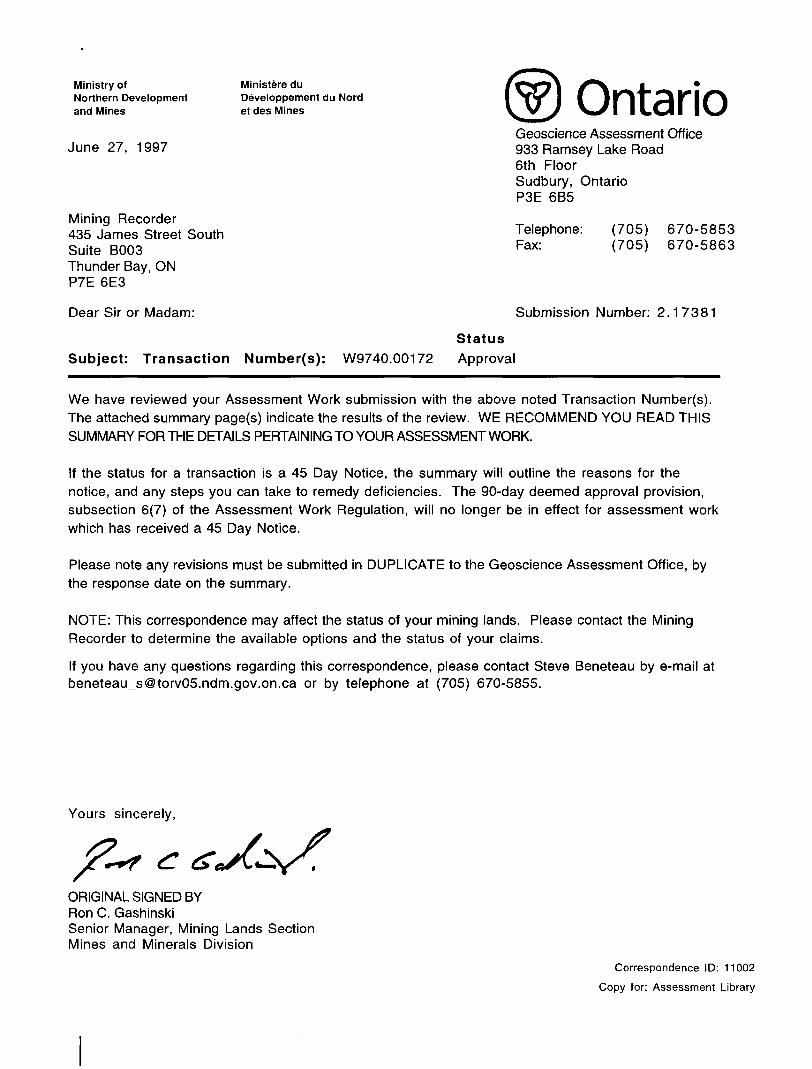
Geoscience Assessment OfficeJune 27, 1997 933 Ramsey Lake Road
6th Floor Sudbury, Ontario P3E 6B5
Mining Recorder435 James Street South Telephone: (705) 670-5853Suite BOOS Fax: ( 705 ) 670-5863Thunder Bay, ONP7E 6E3
Dear Sir or Madam: Submission Number: 2.17381
Status Subject: Transaction Number(s): W9740.00172 Approval
We have reviewed your Assessment Work submission with the above noted Transaction Number(s). The attached summary page(s) indicate the results of the review. WE RECOMMEND YOU READ THIS SUMMARY FOR THE DETAILS PERTAINING TO YOUR ASSESSMENT WORK.
If the status for a transaction is a 45 Day Notice, the summary will outline the reasons for the notice, and any steps you can take to remedy deficiencies. The 90-day deemed approval provision, subsection 6(7) of the Assessment Work Regulation, will no longer be in effect for assessment work which has received a 45 Day Notice.
Please note any revisions must be submitted in DUPLICATE to the Geoscience Assessment Office, by the response date on the summary.
NOTE: This correspondence may affect the status of your mining lands. Please contact the Mining Recorder to determine the available options and the status of your claims.
If you have any questions regarding this correspondence, please contact Steve Beneteau by e-mail at [email protected] or by telephone at (705) 670-5855.
Yours sincerely,
ORIGINAL SIGNED BYRon C. GashinskiSenior Manager, Mining Lands SectionMines and Minerals Division
Correspondence ID: 11002
Copy for: Assessment Library

Work Report Assessment Results
Submission Number: 2.17381
Date Correspondence Sent: June 27, 1997 Assessor: Steve Beneteau
Transaction Number
First Claim Number
W9740.00172 1201606
Section:14 Geophysical MAG 14 Geophysical VLF
Township(s)KLOTZ LAKE
l Area(s) StatusApproval
Approval Date
June 27, 1997
Correspondence to:Mining Recorder Thunder Bay, ON
Resident Geologist Thunder Bay, ON
Assessment Files Library Sudbury, ON
Recorded Holder(s) and/or Agent(s):Steve Anderson TIMMINS, ONTARIO
DONALD MCKINNON TIMMINS, Ontario
RANDALL W SALO THUNDER BAY, Ontario
Page: 1
Correspondence ID: 11002

i-ec "8,060
:!U^^--
M76892 1201604
176910 II3:07:: . IBI07
II7A893 i II820OO || - - -L .
ITfc
o-x ....f---1 --- -
. i 738 lG-295
Fia 3
cii.nti BALTIC RESOURCESProp.niu: KLOTZ LAKE PROPERTY Till.:
CLAIM SKETCH
SPA"APRIL/B?
"OUT
SDA
l ULfM1F/NW
MCKINNON PROSPECT i NOTIMMINS. ONTARIO

Ni
O
O
CA
ST
LE
BA
R
LA
KE
G
-22
0
O)
tt) > O m o i K)
00 O)
-V-V
-i'*o
h-4!
-
^^'-/
g^ni
,rfc—
s
i 121
3470
EflC
KN
ELL
L
AK
E G
-206
O) CD o CD C tp
C/l
c
O
O l ro (D 01
OD
a '.a re 3
Ol
3
Q.
m enO m
5 O
5 m
o DO
o H
N
00 ^
03
O
0H
z o-
z 5
rn
n I A o
n I z CO
b-Tt
'Z
.O
oH
c
fcO
O
33
O>
>
rp
x
l" S
K; S
o,
m
33 -j,
^50^
?
S
Z
33
O
J-
33
B
H,.
-
W
O
1/1 Z
-
O0
.22
-S *
Hi '
.c z
^
33
- -1
^
Do
-; n
2
;
nO C •D
O
00 C
X
-n
> n
m e* 2 z
c 33
m Z 00
x
-o
-o
H H
2
O
oo
5
oozo^c
x -H (S!
o m
x
go
O
S
•o
m D
O
O C m
LO
C Z
Z Z o I o I oo
oc
a m
c
C/1 < 2 '5
CA •o
o o
fr < m
X
oo m O
Z
C
SX
00 O x c oo
* m
O
m
Cir*
CD
m
Q
5 i
>
00
2
O r ^
O
O
O Z
CD O J3
z o zC
3
-*
>F
Foo
H
O
I
C
x
^*
—
3 l
IT,
-H 33 > S
Z o 33 Ci I
O ^
O
03
li oo
O
n
r— z
m
oo
O O
C
H
^
my
z -c
2 LO
n"
.1
C
Z
-o r
Ct
00X
X
!I n C
D00
z
rr 00o
^ ^
r-
00
5i m̂
-o
oo
x-
z
o x o c L l
O
CO CO l ico
3o m T
I
?S m
13 3 3
3
15
lii
z o
.Z
O:
Oz '
s J^
-5
< C
D 33
Z
;HH^r
o^S
|lzi|
:cop
goo
0
5 :3
K"0
Ho
^H^o
siz
33 —
H
o K
m >
> -H
.w o
-a 3
33
i ^
Nn
?P
M
? -
J"C
(c r-
rn (
n m
oo
-. -
O
CO
z 5
rn
f"^
o5 ^
00
o co
" i
5 i
"sslfi
S!5
"-x
m ^
x r
z
> r
y O
n *
m S
5 oO
- c
: m
ife ''1'
rOO
2Z
33
00
2S
OJ
lzis
sSc
glsi
> T
l I >
H: ij
> -o i
3 O
en 2
rn
•'•- ^
t\
m n
~o x H
H
" -*
1za
-xp
ixi
"^
m -i
o T
rn m
2.17
38 l
CD
CO_. i
3D
CO - --l
r\DenCD
rn3DCO— 1
COaam3DCO— 1
COenarn3DCO— 1
.fi.oQ
m33CO—f
r-
enarn3DCO— i
f f-
CJarn3DCO—1
enenorn3DCD— 1
onCJorn3DCO— 1
enenCD
m3DCO-H
-JaCD
rn3DCO— 1
-JenCD
rn3DCO— 1
COaam3DCO— 1
COenO
rn3DCO— 1
CDCDCD
rn3DCO— 1
CGenCJ
m3DC,0-H
i—
CDCDCD
m33CO-H
[ —— -*
ainam3Deo— i
i —i — -oom3DCO— 1
i — -i — -enCD
rn3DCO— i
i — 'roCDCD
rn3DCO— 1
— .rocr,a
rn3DCO— 1
i — ̂eoCDc;jrn3Den— i
, — -tjjenL.O
r*^'3DCO
- -H
i ——
4^aom3DCO— 1
i —4^enCD
rn3DCO—1
1 — -enoO
rn3DCO~H
i — -
enenO
rn3DCO— f
i — -enCDCD
rn3DCO-H
1 — -enenCD
rn3DCO— 1
i — --.Jaan~i3DCO— 1
1 —-Jenom3DCO— 1
—COV—,^
CD
rn3DCO— 1
i —ODen0
rnDDCO—H
i — '
CDCDCD
rn3DCD— 1
!———
CDenCD
m3DCO— l
r\DCDOO
m3Den__ j
r\DOenam3DCO— l
,r\Di — .CDO
rn3DCO— 1
roi — -enCD
m3DCO__ j
roroCDom3DCO— 1
IND
roenCD
rn3DCO-H 1
roeoaCD
m3DCO-H
roCOenCD
m3DCO—1
rv)4^OO
rn33CO— l
ro4^enorn3Den— i
1062
n M n P T MU ,! N u Pi i J j
BflSE L. I Ne:—- -
100 SOUTH
200 SOUTH
300 SOUTH
SHORE LINE
ROAD
HYDRO L l NE
CLAIM POST ASSUMED
CLAIM POST LOCATED
CLAIM L l NE
LOT AND CONCESSION LINE
RA l L L l NE
LEGEND
INSTRUMENT; GEM GSM- l 9
PARAMETER MEASURED: EARTH'S TOTAL MAG FIELD
DIURNALS CORRECTED WITH BASE STATION
ACCURACY: */- InT
CONTOUR INTERVAL: 50 NANO-TESLAS
READING INTERVAL: 25.0 METERS
DATUM SUBTRACTED: 57000nT
CONDUCTOR AXIS: —————————
^ 0 .A JJfp^-
-- 1075 f 1056
1053 j 1049i i
-h 1042 -- 1040
1086 m. -- 1086
\A00 4- IOB?"V -- 1072
1162 " 1168 -- 1180-- 1068 -- 1092 -- 1108
-^J.222 -- 123B -- 124-7
•- 1241 -- 1242 -- 1163
1223|
IMS——'A n n Q n i i T LJH u u kD u u i n 116Z\ f 1135
TOPO LEGEND;:: i n c ^ i ^ nv-J J U U ^ l.., : , ;
-- 1044 f 103
——————————
r*38"1 KC
42F13SW0019 2.17381 KLOTZ LAKE
300 NORTH
200 NORTH
100 NORTH
BRSE LINE
100 SOUTH
200 SOUTH
300 SOUTH
400 SOUTH
500 SOUTH
600 SOUTH
210
l 230 l 00
CDP"1
3D CO —i
rn33en-H
rn33 CO—l
m3D C/) -H
3Den CO
3D CO
rn3D CO—i
rn3D CO—(
3D CO
3D GO-H
rn3DCO -H
m3D CO
rn33 CO—l
33 CO —l
3D CO -H
rn3D CO—H
m3D C/)-H
33 CO
33CO
33 CO
3D CO -H
3D CO -H
rn33cr)
rn33 CO
m33 CI —i
rn33 CO-H
3DCO -H
33 CO -H
rn3D CO—H
rn3DCO
3DCO
3D CO
-O CD CD
3D CO
-JenCD
33en-H
03 CD O
33CO__j
COino m3Dco
CDOo
3Den -H
COin om3D CO.—l
ro o CD om33 CO
rv) O en CD
33 CO
ro
o orn3Den
enCD
33
ro ro o o
m3DCO —l
CI B A f np T /-V 1~\ ' ——l /-~N /^\ T T T~\ yTN T"l /~N ALT I C RESOURCLS
PraperLy : KLOTZ LAKE PROPERTTitl,
CONTOURED AND POSTEDOTA D KiAGNETOME T tR
Prace ssed:S. ANDERSON
Doie: APfv : L 997
Pr-ov l nee : ONTARIO
Scal
Checked:S. ANDERSON
Tawnshl p:KLOTZ LAKE AREA
N.T.S. : 42F/NW
l ng : ADELMAG
McKl NNON PROSPECT NG
T !MMI NS ONTAR i O

200 SOUTH
300 SOUTH
400 SOUTH
500 SOUTH
600 SOUTH
700 SOUTH
800 SOUTH
-Jen0
z;mCO-H
-OO0
51rnCO-H
enen0
x;rnco— i
enOo51rnCO—i
eneno
2: rnCO— i
enOoz:mCO— i
4^eno21rnCO— i
4^o0
21rnCO—i
COenoz: rnCO— i
COo0
z: rnCO—t
roCT:C!
•21rnCO-H
Moo51rnCO-H
i—en0
sirnCO-H
t—-CDO
^:mCO— i
200 SOUTH
300 SOUTH
400 SQjTH
700 SOUTH
800 SOUTH
en o
m co
o o
rn co
en o
m co
o o
rn co
en o
rn co
o o
m co
en o
rn co
o o
co
en o
rn co
o o
rn co
en o
m co
ro o a
rnDI
en a
rnCO
o o
rnCO -H
42F13SW0019 2.17381 KLOTZ LAKE220
TOPO LEGEND
SHORE LINE
ROAD
HYDRO LINE
CLAIM POST ASSUMED
CLAIM POST LOCATED
CLAIM LINE
LOT AND CONCESSION LINE
RAIL LINE
E.EGEND
INSTRUMENT: GEM. GSM-l 9 MAGNETOMETER
PARAMETER MEASURED: EARTH'S TOTAL MAG EI ELD
DIURNALS CORRECTED WITH BASE STATION
ACCURACY: */- InT
CONTOUR INTERVAL: 50 NANO-TESLAS
READING INTERVAL: 25.0 METERS
DATUM SUBTRACTED: 57000nT
........ ALT I C RESOURCEP,ope,tu: KEOTZ EAKE PROPERTY
CONTOURED AND POSTED TOTAL FIELD MAGNETOMETER
Pr-acessed :SDA
Dote APR!L '' 97
ON
:2500
Checked .SDA
Township: KEOTEAKE AREA
PONDMAG
MCKINNON PROSPECTINGT MM INS. ONTARIO

400 NORTH
300 NORTH
200 NORTH
100 NORTH
BRSE EINE
CDenCD
m3Den
CD om3Den
ena
rn3Den
ro
3Den
roenCD
3Den —i
COen CD
3Den
oomX)fin._t
en CD
3Den
en CDCD
3Den
en enCD
3Den
en CDom3Den— H
enen CD
3Den
-.jCD CD
3Den
en a
3Den
enCD CD
3Den
CDenCD
3Den
OD O CD
3Den
CDen CD
3Den_ i
CD CD CD
CO -H
en CD
3D CO...,._j
H",
3D CO-H
U]CD
3Den —i
ro CDCD
3Den
ro enam3Den
eo CD CDm3Den
eoen.CD
3Den
O
mX)en-H
-C*.
enCD
rn3Den
enCDCD
m3Den
en en CDm3Den
CDD oCD
m3Den
en en a
m3Den
O O
3Den
LT\ CD
3Den —i
COoCD
3Den
COenCD
rn3Den
LOCJc:
3Den
CDenCDr~n3Den
ro ooCD
3Den
ro CD en a
3Den
ro
o arn3Den
ro
en o
3Den
ro roCD CD
rn3Den
ro roenCD
3Den
rv 3UJoCD
r3Den--•i
ro eoen CDrn3Den
ro -h- CD CD
3Den
ro -t*, en CD
m3Den
T -4
-- -l -7 -- -l 4 -- -3 1Z
-3 O -- -2 -S -- -4
13 T l 21 -r -l 18 -r -
-2 - -9 -8 -- -7 30 -- -26 27 -- -14 -2 -- -9
4 41 -- -26 36 6 -- -14 -l -- -13 -3 -- -6 -9 -7 -- -14 4
Z3 4 -17 -5 4 II 21 4- -12 21 O -2 -- -11 3 -10 + -3 -8
11 T ID -14-15 12 -r - 12 -6 -l -10
-4 -- 9 -O -- 14 -35 -- 10 -14 -- 5
ro r) ut u
-l -l --f 'T 6 -- -15 2 -- -16 5 4 - 10 -2 -- -10 B -- -8 3 -- -8 4 4- -6 2 -- -7 -5 --l -- -10 7 -- -29 30 -- -29 56 t -37 47 6 -- -15 l
8 -10 -j- 1 -30ll
10 -24 i l -48
19 8 " -19 O27 44 4 -35 46 36 44 -- -32 IB
31 34 4- -3D 9
34 14 -- -31 -2 -- -22 -3 19 4 -- -23 21 -3 -- -16 -5 -- -IB -2 9 -6 -- -9 2 -- -10 -2 -- -11 -4 -- -8 -6 -- -9 -8 - 11 -37 " 10 -36
15 -2 - -17 -5?8 9 -- -30 -6 -- -IB -7 19 2 -- -22 l -- -21 -l 24 -5 -- -19 l -- -21 -64- g -g -- -10 -2 -- -12 -3 -- -14 -5 -- -13 -8-2 4- -3 -2
100 SOUTH -5 -- -12 -423T 15 -- -23 2 -- -E2 4 -- -23 -5 -- 15 l -- -IB 4 -- -21 6 - -21 l -- -21 -4 -- -13 -4 -- -M -7 -- -13 -9 -- -12 -5 -- -13 -O -- -13 -l -- -17 -5 ---5 -- -O -4 4 -13 l -- -18 M T -27 15 -4 -- -l -2 4 -3148 -40
3 -l -- -9 -613 -3 -- -15 -2 -- -i!6 -4 -- -M -2 -2 -- -a -18 " O -8 -- -l -6 -7 ' -12 -- -11 -3 -- -6 -22 -- -l l 44-15 -5 -- 2 -13 l -25 -- -B
10 T-18 -- l -26 -- 8 -20 -- 41 -117 -l -- -12 -2 -- - 5 -16 -- 2 -9 -- 3 -10 8 -- 4 -M -: -- -7 -28 -- -l -24 -- -I -20
-- 2 -27 -- O -15
200 SOUTH 5 -O -- -2 -4 -- 4 -4 -- 5 -2 -- 4
5 -2 -- 3 -6 -- 6 -8 -- B -7 -- 5
2 -5 -- 4 -8 --
-8 -- 5 -3/-- l
300 SOUTH -2 -- 3 -2
-O -- -6 -7 -- -6
400 SOUTH
O -^ -l V -14-
-8 23 -- -22
0+2 -3
EGENESCO S O UT M ID 2411
11 -10 4 10
10 -- \2 -15 9
-5 l 10 -li 10
400 NORTH
300 NORTH
200 NORTH
100 NORTH
BRSE LINE
1CTO SOUTH
200 SOUTH
300 SOUTH
400 SOUTH
500 SOUTH
,1738 lrOPO LEGEND
600 SOUTH
INSTUMENT: GEOMETRICS EM-16
PARAMETERS MEASURED: IN-^HASE AND QUADRATURE
READING INTERVAL: 25M
CONTOUR INTERVAL: 5 UNITS
STATION: CUTLER MAINE NAA-24.0 KHZ.
CONDUCTOR AXIS: —————————
SHORE LINE
ROAD
HYDRO L l NE
CLAIM POST ASSUMED
CLAIM POST LOCATED
CLAIM L l NE
LOT AND CONCESSION L l NE
RAIL LINE
42F13SW0019 2.17381 KLOTZ LAKE 230
200 l 00 150 200
L. Cc :
n3 P'
COf r "i
.T; 3v"T '
".r: 3;; .D
.....J
" Ci— l
eoCD
,.T , 3D
-••l
O CD
GO
C/l CD
C..O- -H
.D•''.O-H
:DLO
CD r D
'ID 3Den.-..-l
enr "T ' -.^
o
3D 3Den
CD
.'D
COH -H
CJOCD
CD
roCDen CD
3Den - -H
••o
CD CD
3Den
mX)en
m3DCO—l
L.
CI lent ALT I C RESOURCESProper LL KLOTZ LAKE PROPERTitl,
VLFCO
SURVEY OURED FRASER F ER
Processe d:S . A jDERSON
Dote : APR !99;
Prov l n :e
ONTARIOScole.
Checked:
S. ANDERSON
Tawnshl p:KLOTZ LAKE AREA
N . T . S . : 42F/NW
l ng :ADELFF
M C K;NNON PROSPECTINGT!MM i NS ONTAR i O
0^

en arn3D CO
CD O
m3D CO—l
enCD
rn3Dco
roCDi—i
m3Dco
r-OenCD
rn3Dco
CO CDCD
rn3D CO
COen a
rn 3D co
Oo
3D CO—\
en CDm3Dco —i
enCD CD
m3Dco
en en CDrn3DCOm__j
en o a
3Den
CD enCD
3Den—i
o a arn 3DCO—i
en o
3D CO
COa orn3DCO
COen arn 3DCO
CD Oa
3D CO
LDeno
3DCO
a aa
3D CO
en orn 3D an—H
o a
3D CO
o
3D CO
Oo
3D CO —l
rv) en a
rn3DCO
COa a
m3D CO -H
COenCDm3DCO
-fc*aCD
rn3D CO
Ula
3D CO
en CD CDm3D CO
en en CD
3D CO
CD CD CD
rn 3D CO
enenCD
3D CO-H
-Ja orn3D CO
en orn3D CO—i
COo o
co
COen a
3Dco
CD Oa
3D CO
CDen o
m3D CO
ro CD oCD
rn3Dco
ro oen a
m3Dco
ro CDCD
3D CO -H
ro
en a
m3D CO
ro ro CD CDrn3D CO —l
ro ro en CD
rn3D CO
-OCO CDCJ
3D CO -H
ro COen CD
m3D CO
ro -t-CDCD
3DCO
roj^ en a
3Dco
400 NORTH
Tl-4
300 NORTH
200 NORTH
100 NORTH
BRSE LINE
100 SOUTH
200 SOUTH
700
IL, V-
/3 r l i 21
l \1if \ c
-31 p\-- -28 /4\-- -24 i 7. -- -23 \ll ~ -22 ' \3 -- -26f
D l J
-30 4B --/-40 37
-IB/ -7 -- V18/ -6 -- -1J -2 l 4- r8 -4 r
-.//-fi -4 -- -4 -3 --
Arn^J-32T X,
ID - -p (l
PROFILE SCALE: icm-20%EGEND TOPO LEGEND
-10 -20 -30 -40
IN5TUMENT: GEOMETRICS EM- l 6
PARAMETERS MEASURED: IN-PHASE AND
READING INTERVAL: 25M
PROFILE SCALE: lcm-20%
[12 1*2 -^ l? -2 -^i M r i *QUADRATURE
- .r\ -1 4 ''' - -i - -
4" \ rO, Zfl \ U3| ff \ -
12 f-3 - 15 .-8 17 TRUb CROSSOVER STATION: CUTLER MAINE NAA-24.0 KH
CONDUCTOR AX i S
MODERATE
STRONGQUADRATURE
300 SOUTH
400 SOUTH
500 SOUTH
600 SOUTH . 1738 lSHORE L l NE
ROAD
HYDRO L l NE
CLAIM POST ASSUMED
CLAIM POST LOCATED
CLAIM LINE
LOT AND CONCESSION L l NE
RAIL LINE
400 NORTH
300 NORTH
200 NORTH
100 NORTH
BRSE LINE
100 SOUTH
200 SOUTH
300 SOUTH
400 SOUTH
500 SOUTH
600 SOUTH
42F13SW0019 2.17381 KLOTZ LAKE
50
240
100 150 200
800 SOUTH
CDa
3D CO
en arn3D CO
ro ro CDCD
rn3D CO
-•H
Cli eni. BALTIC RESOURCESLOTZ LAKE PROPER
Title;
D ROF1LED VLF-EM SURVEY
Processed ;S. ANDERSON
Date :APR; L. 1997
Prav l r ice . ONTARIO
Scalel:25?
-h e c h e d :S. ANDERSON
Tnwnshlp;KLOTZ LAKE AREA
N . T . S . : 42F XNW
Drawlng:ADELPROF
McKi NNON PROSPECT NG
T i MM NS ONTARi O


