60
March 2013 Work Zone Safety Guidelines for Construction, Maintenance, & Utility Operations

March 2013
WorkZoneSafety
Guidelines forConstruction, Maintenance, &Utility Operations
WZ13cover_WZ cover03 (WI) 2/28/13 2:56 PM Page 1

Table of ContentsIntroduction and Fundamental Principles 2Traffic Control Devices 3
Signs 3Channelizing Devices 6Warning Lights 9Pavement Markings 9Arrow Boards 10
Components of a Traffic Control Zone 11Taper Length Criteria for Work Zones 12Buffer Lengths 13Planning the Layout 13Typical Application Diagrams 15
Work Beyond the Shoulder 16Work on Shoulder or Parking Lane 17Shoulder or Parking Lane Closed on Divided Roadway 18Work in Center of Road (Two-Way Traffic, 35 mph or Less) 19Work in Travel Lane (Two-Way Traffic, 35 mph or Less) 20Lane Closure on a Road with Low Volume (Self-Regulating) 21Lane Closure on a Road with Low Volume (Yield Sign) 22Lane Closure on a Two-Lane Road with Stop Signs 23Lane Closure on a Two-Lane Road with Low-Volume (1 Flagger) 24Lane Closure on a Two-Lane Road (2 Flagger Operation) 25Work Near Highway-Rail Grade-Crossing 26Temporary Road Closure 27Surveying Along Centerline of Road with Low-Volume 28Center Turn Lane Closed on a 3-Lane, 2-Way Road 29Lane Shift on a 3-Lane, 2-Way Road 30Lane Closure on a 4-Lane Undivided Road 31Lane Closure on Divided Roadway 32Double Lane Closure on Divided Roadway 33Center Lane Closure on Divided Multi-lane Roadway 34Half Road Closure on Multi-lane Roadway 35Lane Closure in Advance of an Intersection (On Through Road) 37Lane Closure in Advance of an Intersection (On Side Road) 38Lane Closure Beyond an Intersection (On Through Road) 39Lane Closure Beyond an Intersection (On Side Road) 40Lane Closure on Far Side of Intersection 41Closure in the Center of an Intersection 42Street Closure with Detour 43
Mobile Operations 44On the Shoulder 45On a Two-Lane Road 47On a Two-Lane Road Using Flaggers 49On a Multi-Lane Road 51
Pedestrian and Bicyclist Safety 53Sidewalk Closure—Pedestrian Detour 54Sidewalk Closure—Pedestrian Walkway Provided 55
Flagging Procedures 56Worker Safety 57Supervisor’s Checklist 57Liability 58Acknowledgments 58
1

IntroductionThis handbook presents information and guidelines for temporary traffic control, including examples of typical traffic control applications. It applies to construction, maintenance, and utility work zones.
This information is intended to illustrate the principles ofproper temporary traffic control, but it does not establish standards or warrants. Part 6 of the MUTCD and theWisconsin MUTCD Supplement contain the standards fortemporary traffic control. These standards are highlighted in yellow in the text of this handbook.
Fundamental PrinciplesExperience has shown that the following principles will helppromote safe and efficient movement for all road users(motorists, bicyclists, and pedestrians, including persons withdisabilities) through and around work zones while reasonablyprotecting workers and equipment.
1. Make traffic safety and temporary traffic control an integral and high-priority element of every project from planning through design, construction, andmaintenance.
2. Inhibit traffic movement as little as possible.
3. Provide clear and positive guidance to drivers, bicyclists, and pedestrians as they approach and travel through the temporary traffic control zone.
4. Inspect traffic control elements routinely, both day andnight, and make modifications when necessary.
5. Pay increased attention to roadside safety in the vicinity of temporary traffic control zones.
6. Train all persons that select, place, and maintain temporary traffic control devices.
7. Establish proper legislative authority to implement and enforce needed traffic regulations, speed zones,parking controls, and incident management.
8. Keep the public well informed.
9. Make appropriate accommodation for abutting propertyowners, residents, businesses, emergency services, railroads, commercial vehicles, and transit operations.
2

Traffic Control Devices
The following traffic control devices are used in work zones:� Signs � Pavement Markings � Channelizing Devices � Arrow Boards� Warning Lights
Device sizes and quantities shown in this handbook and theMUTCD generally represent minimums. Contract plans or otheragency requirements can exceed these minimums and must be followed.
Signs
Signs used in work zone traffic control are classified as regulatory, guide, or warning. Regulatory signs impose legalrestrictions and shall only be used with permission from the authority with jurisdiction over the roadway. Guide signscommonly show destinations, directions, and distances. Warning signs give notice of conditions along the roadway.
Temporary Warning Signs – With few exceptions, temporarywarning signs for construction, maintenance, and utility workzones shall be diamond shaped, having a black symbol or message on an orange background. As a general rule, thesesigns should be located on the right-hand side of the roadway.Normally, the first advance warning sign used is ROAD WORKAHEAD or UTILITY WORK AHEAD. The END ROAD WORK or ENDUTILITY WORK signs should be used on long-term stationary work lasting more than 7 days.
Size – On expressways and freeways advance warning signsshall be 48 inches by 48 inches. On other roadways where speed limits are 45 mph or greater, they should be 48 inches by 48 inches. Where speed limits are 40 mph or less, 36 inch by 36 inch signs may be used.
Mounting – Temporary post-mounted signs shall be mountedat a height of at least 7 feet in urban areas and 5 feet in ruralareas, measured from the bottom of the sign. Signs mountedon Type III barricades used to close any part of a road or laneshould not cover more than 50 percent of the top two rails or 33 percent of the total area of the three rails. For signsmounted on other portable supports or on barricades usedsolely as a sign support, the bottom of the sign shall be not less than one foot above the traveled way. Sign supports shallbe crashworthy.
3

4
ROADWORKAHEAD
DETOUR500 FT
RIGHT LANECLOSED1000 FT
ROADCLOSED500 FT
7' M
IN
5' M
IN
4' M
IN
6' to 12'
2'
6' to 12'
6'
35MPH
RURAL DISTRICT RURAL DISTRICT WITH ADVISORY SPEED PLAQUE
FOR BUSINESS, COMMERCIAL AND RESIDENTIAL
Paved Shoulder
Walkway
7' M
IN
2'
MIN
A
B
C
Sign Spacing (feet)25-30 35-40 45-55 Expressway/mph mph mph Freeway
A 200* 350 500 1,000
B 200* 350 500 1,500
C 200* 350 500 2,640
Spacing of Advance Warning Signs
Distances shown are approximate. Adjust sign spacing for curves, hills,intersections, driveways, and other obstructions to improve sign visibility.* Where field conditions warrant, spacing may be as short as 100 feet.

Illumination and Retroreflectorization – All signs usedduring hours of darkness shall be made of retroreflectivematerial or illuminated. Street or highway lighting is notregarded as meeting requirements for sign illumination.
Removal – When work is suspended for short periods, all signs that are no longer appropriate shall be removed,covered, or laid flat so they are not visible to traffic.
5
PORTABLE AND TEMPORARY MOUNTINGS
96" M
IN
High Level Warning Device (Flag Tree)
See Note 5 on page 48.
Orange Flag(optional)
UTILITYWORKAHEAD
Orange Flag(optional)
above 1' MINtraveled way
above 1' MINtraveled way
Portable sign supports should not be used for more than seven continuous days.

Portable Changeable Message Signs (PCMS) – These candisplay a variety of messages, but are typically used to display“real-time” or changing information about closures, delays orother temporary traffic conditions. They should only be usedto supplement other signs, and not to substitute for anyrequired signs. If used during lane or ramp closures, placePCMS in advance of locations where stopped traffic is expected and/or prior to exits to alternate routes. PCMSshould not display more than two screens or displays, whichshould be readable twice at the usual roadway speed limit.More than one PCMS should be used if the message exceedstwo screens. Avoid using messages that would cause abrupt or inappropriate actions by drivers. PCMS should bedelineated with retroreflective channelizing devices.
Channelizing DevicesChannelizing devices are used to warn and alert drivers, bicyclists and pedestrians of conditions in work zones, to separate traffic from the work area, and to guide and directtraffic. Channeli z ing devices include cones, tubular markers,vertical panels, drums, and barricades.
Cones are used most commonly for short-duration mainte-nance and utility work. Cones used at night shall be retro-reflectorized as shown on page 8. Drums are used most commonly where they will remain in place for a prolongedperiod. Channelizing devices shall be crashworthy. Ballastshall not be placed on top of channelizing devices.
Spacing – Space channelizing devices so it is apparent thatthe roadway or work area is closed to traffic. There are sever-al rules of thumb that can be used to guide you in the properspacing of channelizing devices.
1. The maximum spacing between devices in a tapershould be a distance, in feet, which is approximatelyequal to the speed limit in mph. For example, if thetaper is on a street with a 35 mph speed limit, thedevices should be spaced about 35 feet apart.
2. Two-way traffic tapers should be made up of at leastfive (5) channelizing devices.
3. The maximum spacing between devices in a buffer orwork area should be a distance, in feet, of 2 times thespeed limit in mph. For example, if the speed limit is35 mph, the devices in the buffer and work areashould not be more than 70 feet apart.
6

4. Shorter spacing between devices in the buffer andwork area is appropriate under some conditions toenhance the separation between the work area andthe open traffic lane(s). Examples are in urban areas,on congested roadways, during work at night, alongdrop offs or where vehicles are frequently knockingover the devices.
5. Additional devices are appropriate to outline the pathfor turning vehicles near intersections or where exist-ing pavement markings conflict with the temporarytravel path.
Number of Channelizing Devices Needed
The number of devices in the buffer/work area: lower number is forspacing of 2 times the speed; higher number is for spacing equal to speed.
7
35 MPH 45 MPH 55 MPH 65 MPH
Length Buffer/ Buffer/ Buffer/ Buffer/(ft) Taper Work Taper Work Taper Work Taper Work100 5 2 – 3 5 2 – 3 5 2 – 3 5 2 – 3
150 6 3 – 5 5 2 – 4 5 2 – 3 5 2 – 3
200 7 3 – 6 6 3 – 5 5 2 – 4 5 2 – 4
250 9 4 – 8 7 3 – 6 6 3 – 5 5 2 – 4
300 10 5 – 9 8 4 – 7 7 3 – 6 6 3 – 5
350 11 5 – 10 9 4 – 8 8 4 – 7 7 3 – 6
400 6 – 12 10 5 – 9 9 4 – 8 8 4 – 7
450 7 – 13 11 5 – 10 10 5 – 9 8 4 – 7
500 8 – 15 13 6 – 12 11 5 – 10 9 4 – 8
550 8 – 16 14 7 – 13 11 5 – 10 10 5 – 9
600 9 – 18 15 7 – 14 12 6 – 11 11 5 – 10
650 10 – 19 16 8 – 15 13 6 – 12 11 5 – 10
700 10 – 20 17 8 – 16 14 7 – 13 12 6 – 11
800 12 – 23 19 9 – 18 16 8 – 15 14 7 – 13
900 13 – 26 10 – 20 18 9 – 17 15 7 – 14
1000 15 – 29 12 – 23 20 10 –19 17 8 – 16

Notes
1. Stripes on barricade rails shall slope downward at an angle of 45 degreestoward the direction traffic is to pass.
2. Barricade rail stripe widths shall be 6 inches except where rail lengths areless than 36 inches, then 4 inch wide stripes may be used.
3. The sides of barricades and vertical panels facing traffic shall have retro -reflective rail faces. Drums, cones, and tubular markers shall have retro -reflective bands as shown above.
8
8'' to 12"
For panels 36" or greaterstripes are 6"
24" M
IN
VERTICAL PANEL
36" M
IN
36"
MIN
IMUM
45
4" or 6"4" or 6"
8'' to 12'' 4'' to 6''
45
3' M
IN2' MINIMUM
18'' MINIMUM
TYPE I BARRICADE DRUM
WARNING LIGHT(Optional)
WARNING LIGHT(Optional)
8'' to 12''
8'' to 12''
8'' to 12''45 5'
MIN
4' MINIMUM
TYPE III BARRICADE
WARNING LIGHT(Optional)
8'' to 12''
8'' to 12''45
3' M
IN
12" M
AX
2' MINIMUM
TYPE II BARRICADEDIRECTION INDICATOR BARRICADE
WARNING LIGHT(Optional)
8''
12''
3'
2'
18'' M
IN
18'' M
IN
CONES AND TUBULAR MARKERS
Day and 40 mph or Less 4'' collar
3''-4'' 2''3'' 2''-6"3''
28'' M
IN
Night or 45 mph or Higher
6'' collar
28'' M
IN to
36''
MAX4'' to 6''
Mor
e th
an 3
6''
2''3''
2'' MIN

Warning Lights
Warning lights may supplement retroreflectorization on warning signs and channelizing devices. They are especiallyuseful in areas prone to fog or inclement weather. Warninglights shall be securely mounted at a minimum mountingheight of 30 inches. The principal types and uses of warning lights are:
1. Low Intensity Flashing Lights (Type A)May be mounted on barricades or drums to warn of an isolated hazard at night. They may also be mounted on signs. They shall not be used on a series of devices used for delineation.
2. High Intensity Flashing Lights (Type B) May be mounted on advance warning signs, or on independent supports to draw attention to extreme hazards both day and night.
3. Low Intensity Steady-Burn Lights (Type C) May be used in a series to delineate the edge of the travelway and channelize traffic at night.
4. Low Intensity 360° Steady-Burn Lights (Type D) May be used in a series to delineate the edge of the travelway and channelize traffic at night.
Pavement Markings
For long-term stationary projects, follow the guidelines of Part 6 of the MUTCD in placing and removing pavementmarkings. The colors of temporary pavement markings and delineators shall follow the same standard as permanent markings. When used to enhance the visibility of the road- way edge, white is required along both sides of two-way roadways and the right side of one-way roadways. Yellow isrequired on the left side of one-way roadways. Centerlinesare yellow when separating opposing directions of traffic.Lane lines are white when separating lanes going the same direction.
For projects that are not long-term and where existing pavement marking conflicts with the temporary travel path,additional signing and channelizing devices are appropriate.
9

Arrow BoardAn arrow board in the arrow or chevron mode shall only beused for lane closures on multilane roadways. An arrow boardshall not be used on a multilane roadway to shift all lanes oftraffic at one location. An arrow board shall only be used inthe caution mode for shoulder work, blocking the shoulder,roadside work near the shoulder, or when one lane on a twolane, two-way roadway is closed. Arrow boards should not beused without signs or other devices and should be delineatedwith retroreflective channelizing devices.
Board Roadway Min. Min. # Min. LegibilityType Speed Size Lamps DistanceA 25-30 mph 24“ x 48” 12 1/2 mile
B 35-40 mph 30“ x 60” 13 3/4 mile
C ≥ 45 mph 48“ x 96” 15 1 mile
D * * 12 1/2 mile
10
Merge Right
Merge Right
Merge Right
Merge Right or Left
BOARD DISPLAYElement layout for Type C Board: right shown, left similar
OPERATINGMODE
At least one of the next 3 modes shall be provided:
or
(preferred)
At least one of these 2 modes shall be provided:
The following mode shall be provided:Flashing Double Arrow
Sequential ArrowNot for use on
WisDOT highways
Sequential ChevronNot for use on
WisDOT highways
Flashing Caution or
Alternating Diamond Caution
Flashing Arrow
Mobile operations on high-speed roads may use 30” x 60” Arrow Boards.*Type D arrow shaped boards are intended for use on authorized
vehicles. Type D arrow length is 48” and arrowhead width is 24”.

Components of a Traffic Control Zone
The traffic control zone is the distance between the firstadvance warning sign and the point beyond the work area where traffic is no longer affected. Below is a diagramshowing the components of a traffic control zone.
11
Buffer Area
Downstream Taper
ADVANCE WARNING AREA tells traffic what to expect ahead
TRANSITION AREA moves traffic out of its normal path
BUFFER AREA (recommended)
provides protection for traffic and workers
WORK AREA set aside for
workers, equipment, and material storage
Shoulder Taper
Lateral Buffer Area
TERMINATION AREA
lets traffic resume normal driving

Taper Length Criteriafor Work Zones
The table below lists the five types of tapers and their lengthsused in temporary traffic control. The length of each type oftaper is based on formulas using the speed of the traffic andthe width of the offset (or lane width).
Type of Taper
Merging Taper – The number of lanes is reduced on a multilane road
Shifting Taper – A lateral shift, but no reduction in the number of travel lanes
Shoulder Taper –The shoulder is closed
Two-way Traffic Taper – Opposing directions of traffic share one open lane
Downstream Taper – The work area ends and traffic resumes normal driving (use is optional)
Formulas for L
Speed Limit Formula
40 MPH or less L = WS2 / 60
45 MPH or greater L = W x S
L = Taper Length in feetW = Width of offset (lane width or lane shift) in feetS = Posted speed, off-peak 85th percentile speed prior to
work starting, or the anticipated operating speed in mph
Taper Length
L minimum
1⁄ 2 L minimum
1⁄ 3 L minimum
50 feet minimum100 feet maximum
50 feet minimum100 feet maximum
L (feet)Speed Width of offset (ft)(mph) 10 11 12 1525 105 115 125 160
30 150 165 180 225
35 205 225 245 310
40 270 295 320 400
45 450 495 540 675
50 500 550 600 750
55 550 605 660 825
65 650 715 780 975
12

Buffer LengthsA buffer area is recommended to separate traffic from thework area or oncoming vehicles and provide recovery space for an errant vehicle. The buffer area should not include anywork activity nor storage of equipment, vehicles or material.
Suggested Buffer Lengths
A lateral buffer area may also be used. Its width should bebased on conditions at the work site.
Planning the LayoutExercise judgement when planning temporary traffic control.Consider duration of work, location and road characteristics.
Duration of WorkAs a general rule, the longer the operation will last, the moretraffic control devices are needed.
Long-term stationary Work at a location more than 3 days.
Intermediate-term stationary Work at a location morethan one daylight period up to 3 days or night time worklasting more than 1 hour.
Short-term stationary Daytime work at a location for morethan 1 hour in a single daylight period.
Short duration Work at a location up to 1 hour.
Mobile Work that moves intermittent ly or continuously.
Location of WorkGenerally, the closer the work is to traffic, the more controldevices are needed. For example, when a lane is closed on amulti-lane road for a stationary operation, a merging taperusing channelizing devices and advance warning signs shallbe provided. When paved shoulders having a width of 8 feetor more are closed, at least one advance warning sign andchannelizing devices shall be used to close the shoulder.
13
Speed (mph) Length (ft)20 115
25 155
30 200
35 250
40 305
Speed (mph) Length (ft)45 360
50 425
55 495
60 570
65 645

Roadway CharacteristicsThe traffic control layout must take into account traffic volumes, speed, roadway alignment, highway-rail gradecrossings, intersections, pedestrians, and bicycles. Generally,more traffic control is required where volumes and/or speedsare high, visibility is poor, and conflicts exist due to rail crossings, intersections, pedestrians, and bicycles. If trafficbackups are expected during lane closures, place additionalsigns further in advance to warn drivers of the closures before they encounter stopped traffic.
Low Volume – Several typical diagrams in these guidelinesare appropriate only for roads with low volumes. As a generalrule, roads with low volumes have an average daily traffic volume (ADT) less than 400 vehicles per day. If the traffic volumes are not known, the following rule of thumb can beused to determine if the road can be treated as low volume.
Rule of Thumb – Count the number of vehicles thatpass a single reference point over a five (5) minuteperiod. If not more than three vehicles pass the reference point in that period, then the road can be considered low volume.
In addition, give consideration to local nearby facilities, such as schools, manufacturing plants, and other uses thatgenerate special traffic. Also consider whether the work zone is subject to peak hour traffic increases. Peak hours areusually 6-9 a.m. and 3-6 p.m., but will vary in different areas.
Rail Crossings – If there is a rail crossing near the work area,coordination with the railroad company should occur beforework starts. Lane restrictions, flagging or other operationsshall not create conditions where vehicles can be stopped on the railroad tracks. If traffic backups are likely to extendthrough the crossing, see page 26 and page 36, Note 8.
Reduced Speeds – Speed limits should be reduced only inthe portion of the temporary traffic control zone where there are geometric or physical restrictions, such as closed or narrowed lanes. Reductions are typically no more than 10 mph. Orange advisory speed plaques shall only be usedon the same support as a warning sign and shall not be usedunless the authority with jurisdiction over the roadway hasdetermined the recommended advisory speed.
14

Typical Application DiagramsThe following diagrams are examples of the application of standards, guidance, and options in the MUTCD, theWisconsin Supplement and accepted practices.
These typical layouts are not a substitute for engineeringjudgment and need to be adapted to fit the conditions of a particular site.
Contract plans or other agency documents often containapplicable layouts required by the contract.
The diagrams are not to scale, and the number of channel -izing devices shown might not be the number needed at the work site. Use the tables on the typical diagrams to determine taper and buffer lengths, and use pages 6–7 forguidance on the spacing and number of devices.
The notes and tables on the diagrams provide importantinformation. Read them carefully before using the diagrams.
The diagrams and tables generally indicate minimums. Formore information, refer to Part 6 of the MUTCD and theWisconsin MUTCD supplement. These contain the standardsfor work zone traffic control.
15
Channelizing Device
Arrow Board
Flagger Symbol
Sign Support
Surveyor
Work or Shadow Vehicle with activated high intensity light
High Level Warning Device
Work Area
Warning Sign
Work or Shadow Vehicle with Truck-Mounted Attenuator (TMA)
Type III Barricade
Legend
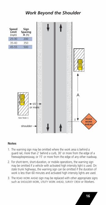
Work Beyond the Shoulder
Notes
1. The warning sign may be omitted where the work area is behind a guard rail, more than 2’ behind a curb, 30’ or more from the edge of afreeway/expressway, or 15’ or more from the edge of any other roadway.
2. For short-term, short-duration, or mobile operations, the warning signmay be omitted if a vehicle with activated high intensity light is used. Onstate trunk highways, the warning sign can be omitted if the duration ofwork is less than 60 minutes and activated high intensity lights are used.
3. The ROAD WORK AHEAD sign may be replaced with other appropriate signssuch as SHOULDER WORK, UTILITY WORK AHEAD, SURVEY CREW or Workers.
16
ROAD WORK AHEAD
A
15' or more
shoulder
See Note 1
Speed SignLimit Spacing(mph) A (ft)25-30 200
35-40 350
45-55 500
17
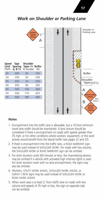
Work on Shoulder or Parking Lane
Notes
1. Encroachment into the traffic lane is allowable, but a 10-foot minimumtravel lane width should be maintained. A lane closure should be considered if there is encroachment on roads with speeds greater than35 mph, or for other conditions where workers, equipment, or the workactivity would benefit from the lateral buffer (see pages 22 and 23).
2. If there is encroachment into the traffic lane, a ROAD NARROWS signmay be used instead of SHOULDER WORK. For roads with low volume,the SHOULDER WORK or ROAD NARROWS sign can be omitted.
3. For short duration work (60 minutes or less), the channelizing devicesmay be omitted if a vehicle with activated high intensity lights is used.For short duration work with no lane encroachment, the signs may also be omitted.
4. Workers, UTILITY WORK AHEAD, SHOULDER WORK AHEAD, or SURVEY CREW signs may be used instead of SHOULDER WORK or ROAD WORK AHEAD.
5. When work area is at least 2’ from traffic lane on roads with low volume and speeds of 35 mph or less, the sign on opposite side can be omitted.
Buffer
ShoulderTaper
ROADWORKAHEAD
A
B
ROADWORKAHEAD
A
SHOULDERWORK
(1/3 L)
See Note 2
Shoulder or Parking Lane
Speed Sign ShoulderLimit Spacing Taper (ft) Buffer(mph) A, B (ft) 10’ shoulder (ft)
25 200 35 155
30 200 50 200
35 350 70 250
40 350 90 305
45 500 150 360
50 500 170 425
55 500 185 495

Shoulder or Parking Lane Closedon Divided Roadway
Notes
1. SHOULDER CLOSED signs shouldbe used on limited-access highways where there is noopportunity for disabled vehiclesto pull off the traveled way.
2. For short-term stationary work,one SHOULDER CLOSED warningsign can be omitted.
3. For short duration work (60 minutes or less), the channelizing devices can be omitted if a vehicle with activated high intensity lights is used. For short duration work with no laneencroachment, the signs can also be omitted.
4. UTILITY WORK AHEAD or Workers signs can be used instead of the warning signs shown.
5. If the parking lane is used as a traffic lane follow the lane closure layout. See page 32.
Buffer
ShoulderTaper
ROADWORKAHEAD
B
RIGHTSHOULDER
CLOSEDAHEAD
RIGHTSHOULDER
CLOSED
ROADWORKAHEAD
RIGHTSHOULDER
CLOSEDAHEAD
RIGHTSHOULDER
CLOSED
(1/3 L)
1/2 A
1/2 A
or OR
(optional)
Truck MountedAttenuator (optional)See Note 7 on page 46
Speed Sign ShoulderLimit Spacing (ft) Taper (ft) Buffer(mph) A B 10’ shoulder (ft)
35 350 350 70 250
40 350 350 90 305
45 500 500 150 360
50 1000 1500 170 425
55 1000 1500 185 495
60 1000 1500 200 570
65 1000 1500 220 645
18

19
Work in Center of Road(Maintaining Two-Way Traffic, 35MPH or Less)
Notes
1. Additional advance warning signs can be used such as ROADNARROWS or Reverse Curve/Turnsigns. The Reverse Curve/Turnsign is appropriate for larger deviations in the travel path.
2. Channelizing devices and high level warning devices may be eliminated on roads with low volumes if a work vehicle with activated high intensity lights is used.
3. The Large Arrow sign can be used instead of the Keep Right or Down Arrow sign where space permits.
Speed Sign ShiftingLimit Spacing Taper (ft) Buffer(mph) A, B (ft) 5’ 10’ (ft)
25 200 30 55 155
30 200 40 75 200
35 350 55 105 250ROADWORKAHEAD
A
ShiftingTaper
Buffer
ROADWORKAHEAD
10'MIN
A
(optional)
Buffer
ShiftingTaper
10'MIN
OR
OR
(1/2 L)
(1/2 L)
OR
OR
See Note 2
20
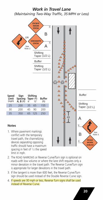
Work in Travel Lane(Maintaining Two-Way Traffic, 35MPH or Less)
Notes
1. Where pavement markingsconflict with the temporarytravel path, the channelizingdevices separating opposingtraffic should have a maximumspacing in feet of 1⁄ 2 the speedlimit in mph.
2. The ROAD NARROWS or Reverse Curve/Turn sign is optional on roads with low volume or where the lane shift requires only a minor deviation in the travel path. The Reverse Curve/Turn sign is appropriate for larger deviations in the travel path.
3. If the tangent is more than 600 feet, the Reverse Curve/Turn sign should be used instead of the Double Reverse Curve sign.
4. If speeds are 30 mph or less, Reverse Turn signs shall be used instead of Reverse Curve.
ROADNARROWS
A
ROADWORKAHEAD
ROADWORKAHEAD
B
A
B
Buffer
Buffer
10' MIN
Shifting Taper
Shifting Taper
Shifting Taper
10' MIN
OR
(1/2 L)
(1/2 L)
(1/2 L)
See Note 2
See Note 3
4S
Speed Sign ShiftingLimit Spacing Taper (ft) Buffer(mph) A, B (ft) 6’ 12’ (ft)
25 200 35 65 155
30 200 45 90 200
35 350 65 125 250

21
Lane Closure on a Road with Low Volume(No Flagger, Traffic Self-Regulating, 35MPH or Less)
Notes
1. This layout may be used where work areas are short, sight distance is good, and traffic can readily see the roadway beyond.
2. Set the buffer area lengths based on space at the site. The total length of the temporary traffic control zone must be short enough that drivers can see approaching traffic beyond the work area.
3. Where traffic does not self-regulate effectively, one or two flaggers,a YIELD sign, or STOP signs for each direction near the beginning of the tapers shall be used with appropriate, advanced warning signs. See pages 22 through 26.
ROAD WORK AHEAD
100'
ROAD WORK AHEAD
ONE LANE ROAD
AHEAD
A
B
50' MIN to 100' MAX
Taper
Buffer
ONE LANE ROAD
AHEAD
A
B
(optional)
Speed SignLimit SpacingA, B (ft) (ft)
25 200
30 200
35 350

Lane Closure on a Two-Lane Road with Low Volume
(with Yield Sign)
Notes
1. This layout may be used when volume is low, work area short, sightdistance good, and traffic can see beyond the work area. It shall not be used on a state-trunk highway or any other roadway officially designated as a “through” highway.
2. The YIELD sign shall only be used with permission from the authorityhaving jurisdiction over the roadway.
3. Set the buffer area lengths based on space at the site. The total length of the temporary traffic control zone must be short enough that driverscan see approaching traffic beyond the work area.
4. Yield Ahead symbol sign may be used.
22
ROAD WORK AHEAD
Buffer (optional)
ROAD WORK AHEAD
YIELD AHEAD
100' max
ONE LANE ROAD
AHEAD
ONE LANE ROAD
AHEAD
A
B
C
B
C
50' MIN to 100' MAX 15'
Taper Buffer
(optional)
(optional)
Optional
(optional)
END ROAD WORK
(optional)
END ROAD WORK
YIELD
See Note 4
Speed SignLimit Spacing(mph) A, B, C (ft)
25 200
30 200
35 350
40 350
45 500
50 500
55 500

Lane Closure on a Two-Lane Road with Stop Signs (ADT Less Than 1000)
Notes
1. Consider using this layout when ADT is less than 1000, work area isshort, sight distance good, and traffic can see beyond the work area. It could be appropriate for ADT above 1000 if limited to off-peak hours.
2. STOP signs shall only be used with permission from the authority having jurisdiction over the roadway.
3. Determine buffer area length based on space at the site. Total length ofthe temporary traffic control zone must be short enough that drivers from both directions can see approaching traffic beyond the work area.
4. Stop Ahead symbol sign may be used.
23
ROAD WORK AHEAD
Buffer (optional)
Buffer (optional)
ROAD WORK AHEAD
100' max
ONE LANE ROAD
AHEAD
ONE LANE ROAD
AHEAD
STOP AHEAD
STOP AHEAD
B A
A
C
B
C
50' MIN to 100' MAX 15'
Taper
(optional)
(optional)
END ROAD WORK
(optional)
END ROAD WORK
Optional
See Note 4
See Note 4
Speed SignLimit Spacing(mph) A, B, C (ft)
25 200
30 200
35 350
40 350
45 500
50 500
55 500
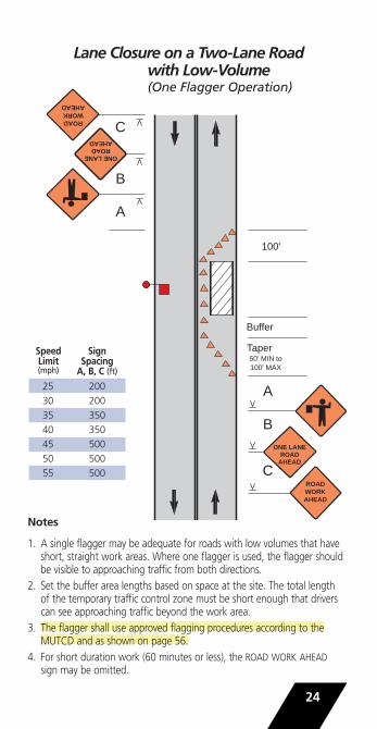
Lane Closure on a Two-Lane Road with Low-Volume (One Flagger Operation)
Notes
1. A single flagger may be adequate for roads with low volumes that haveshort, straight work areas. Where one flagger is used, the flagger shouldbe visible to approaching traffic from both directions.
2. Set the buffer area lengths based on space at the site. The total length of the temporary traffic control zone must be short enough that driverscan see approaching traffic beyond the work area.
3. The flagger shall use approved flagging procedures according to the MUTCD and as shown on page 56.
4. For short duration work (60 minutes or less), the ROAD WORK AHEADsign may be omitted.
24
ROAD WORK AHEAD
100'
ROAD WORK AHEAD
ONE LANE ROAD
AHEAD
ONE LANE ROAD
AHEAD
A
A
B
C
B
C
50' MIN to 100' MAX
Taper
Buffer
Speed SignLimit Spacing(mph) A, B, C (ft)
25 200
30 200
35 350
40 350
45 500
50 500
55 500

25
Lane Closure on a Two-Lane Road(Two Flagger Operation)
Notes
1. The flaggers shall use approvedflagging procedures accordingto the MUTCD and as shownon page 56.
2. For short duration work (60 minutesor less), the ROAD WORK AHEADsign may be omitted.
ROAD WORK AHEAD
200' to
300' 100'
ONE LANE ROAD
AHEAD
Buffer
ROAD WORK AHEAD
ONE LANE ROAD
AHEAD
(Optional)
(Optional)
END ROAD WORK
END ROAD WORK
A
A
B
C
C
B
A
A
50' MIN to 100' MAX
Taper
Speed SignLimit Spacing Buffer(mph) A, B, C (ft) (ft)
25 200 155
30 200 200
35 350 250
40 350 305
45 500 360
50 500 425
55 500 495

Work Near Highway-Rail Grade-Crossing
Notes
1. Minimize the chance that vehicles might be stopped within 25’ of the near rail. Coordination with the railroad company should occur before work starts.
2. If queuing of vehicles across active rail tracks cannot be avoided,a flagger shall be provided at the highway-rail grade crossing toprevent vehicles from stopping within the crossing.
3. The flaggers shall use approved flagging procedures accordingto the MUTCD and as shown on page 56.
4. For short duration work (60 minutes or less), the ROAD WORK AHEAD sign may be omitted.
26
ROAD WORK AHEAD
200' to 300'
ONE LANE ROAD
AHEAD
Extended Buffer
ROAD WORK AHEAD
ONE LANE ROAD
AHEAD
(Optional)
(Optional)
END ROAD WORK
END ROAD WORK
A
A B
C
C
B
A
A 50' MIN to 100' MAX
Taper
CROSSING RAIL R
OAD
CROSSING RAIL ROAD
100'
Speed SignLimit Spacing(mph) A, B, C (ft)
25 200
30 200
35 350
40 350
45 500
50 500
55 500
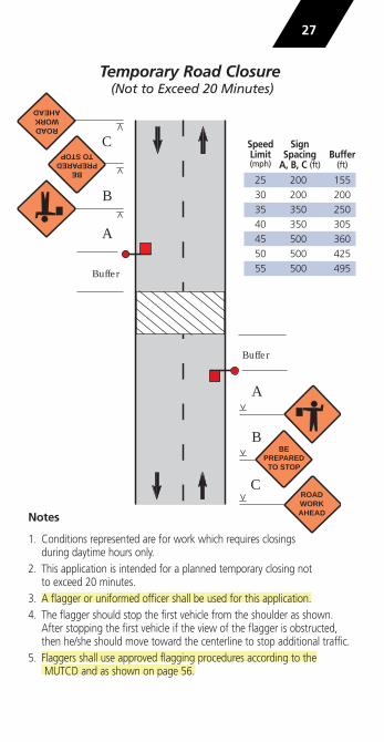
Temporary Road Closure(Not to Exceed 20 Minutes)
Notes
1. Conditions represented are for work which requires closingsduring daytime hours only.
2. This application is intended for a planned temporary closing not to exceed 20 minutes.
3. A flagger or uniformed officer shall be used for this application.4. The flagger should stop the first vehicle from the shoulder as shown.
After stopping the first vehicle if the view of the flagger is obstructed,then he/she should move toward the centerline to stop additional traffic.
5. Flaggers shall use approved flagging procedures according to the MUTCD and as shown on page 56.
Buffer
ROAD WORK AHEAD
C
B
A
Buffer
BEPREPARED
TO STOP
ROAD WORK AHEAD
A
B
C
BEPREPARED
TO STOP
Speed SignLimit Spacing Buffer(mph) A, B, C (ft) (ft)
25 200 155
30 200 200
35 350 250
40 350 305
45 500 360
50 500 425
55 500 495
27

Surveying Along Centerline of Road with Low Volume
Notes
1.Cones should be 6”-12”on either side of center-line. Cones may be omitted for a cross-sectionsurvey. For surveys on theshoulder or road edge,cones may be placedalong the edge line.
2.A flagger should be usedwhen workers cannotwatch for traffic. If workis along the shoulder, the flagger may be omitted.
3. For surveying on the centerline of a road with high-volume,one lane shall be closed using layouts shown on page 25.
4.A high-level warning device may be used to protect a surveying device, such as a target on a tripod.
5. ROAD WORK AHEAD signs may be used in place of SURVEY CREW signs.
SURVEYCREW
B
A
SURVEYCREW
B
A
Buffer
10’ MIN to edge of pavement or outside edge of paved shoulder
Buffer
28
Speed SignLimit Spacing Buffer(mph) A, B, C (ft) (ft)
25 200 155
30 200 200
35 350 250
40 350 305
45 500 360
50 500 425
55 500 495

Center Turn Lane Closedon a Three-Lane, Two-Way Road
Note
1.Use turn restrictions or closedriveways located in theworkzone as appropriate.
29
Speed Sign ShiftingLimit Spacing Taper (ft) Buffer(mph) A, B (ft) for 12’ lane (ft)
25 200 65 155
30 200 90 200
35 350 125 250
40 350 160 305
45 500 270 360
50 500 300 425
55 500 330 495
ROAD WORK AHEAD
B
A
Shifting Taper
Shifting Taper
Buffer
ROAD WORK AHEAD
B
Buffer
A
CENTER LANE
CLOSED AHEAD
CENTER LANE
CLOSED AHEAD
(1/2 L)
(1/2 L)
(optional)
(optional) (optional)

Lane Shift on a Three-Lane, Two-Way Road
Notes
1.Use turn restrictions or close driveways located in the work-zone as appropriate.
2.If speeds are 30 mph or less,Reverse Turn signs shall be usedinstead of Reverse Curve.
30
ROADWORKAHEAD
B
A
ShiftingTaper
ShiftingTaper
ShiftingTaper
Buffer
ROADWORKAHEAD
B
A
Buffer
ShiftingTaper
A
CENTERLANE
CLOSEDAHEAD
CENTERLANE
CLOSEDAHEAD
(1/2 L)
(1/2 L)
(1/2 L)
(1/2 L)
(optional)
(optional)
(optional)(optional)
(optional)
(optional)OR
OR
See Note 3 on page 20
Speed Sign ShiftingLimit Spacing Taper (ft) Buffer(mph) A, B (ft) for 12’ lane (ft)
25 200 65 155
30 200 90 200
35 350 125 250
40 350 160 305
45 500 270 360
50 500 300 425
55 500 330 495

31
Lane Closure on a Four-Lane Undivided Road
Notes
1. An arrow board is optional based on traffic volume, speed,and visibility. Generally, it is agood practice on roads withspeeds of 35 mph or greater.When used, it should be placednear the beginning of the taperor on a vehicle in the work area.
2. If an arrow board is not used, aLarge Arrow sign or directionalindicator barricades in the tapercan be used for added guidance.
Buffer
MergingTaper
ROADWORKAHEAD
Buffer
C
B
A
LEFTLANE
CLOSEDAHEAD
A100'
A
A
ROADWORKAHEAD
(optional)
(optional)
(optional)See Notes 1 and 2
ENDROAD WORK
ENDROAD WORK
( L)
Speed Sign MergingLimit Spacing Taper (ft) Buffer(mph) A, B, C (ft) for 12’ lane (ft)
25 200 125 155
30 200 180 200
35 350 245 250
40 350 320 305
45 500 540 360
50 500 600 425
55 500 660 495

32
Lane Closure on Divided Roadway
Notes1. When a side road intersects
the roadway within the workzone, additional devices shallbe erected to channelize traffic to/from the side road, and a ROAD WORK AHEAD sign shall be placed on each sideroad approach.
2. An arrow board shall be usedwhen a freeway lane is closed.When more than one freewaylane is closed, a separate arrow board shall be used for each lane closed.
3. Except for freeways, an arrow board is optional based on traffic volume,speed, and visibility. Generally, it is a good practice where speeds are 35 mph or greater. When used, it should be placed near the beginningof the taper or on a vehicle in the work area.
4. If an arrow board is not used, a Large Arrow sign or directional indicatorbarricades in the taper can be used to provide added guidance.
Buffer
100 ft500 ft
A
B
C
A
B
C
RIGHTLANE
CLOSEDAHEAD
Merging Taper (L)
Shoulder Taper (1⁄3 L)
Truck MountedAttenuator (optional)See Note 7 on page 46.
ROADWORKAHEAD
RIGHTLANE
CLOSEDAHEAD
(optional)
(optional)
ENDROAD WORK
ENDROAD WORK
See Notes 2 and 3
ROADWORKAHEAD
Speed Sign MergingLimit Spacing (ft) Taper (ft) Buffer(mph) A B C for 12’ lane (ft)
30 200 200 200 180 200
35 350 350 350 245 250
40 350 350 350 320 305
45 500 500 500 540 360
50 1000 1500 2640 600 425
55 1000 1500 2640 660 495
60 1000 1500 2640 720 570
65 1000 1500 2640 780 645

Double Lane Closure on Divided Roadway
Notes
1. When a side road inter-sects the roadway within the work zone, additionaldevices shall be erected to channelize traffic to/ from the side road, and a ROAD WORK AHEAD sign shall be placed on each side road approach.
2. An arrow board shall be used for each freeway lane closed. The second arrow board should be placed near the beginning of the second merging taper or on a vehicle in the work area.
33
Buffer
Merging Taper (L)
ROADWORKAHEAD
AA
A
B
C
A
B
C2
RIGHT LANESCLOSEDAHEAD
2RIGHT LANES
CLOSEDAHEAD
Merging Taper (L)
(optional)200' (optional)
ENDROAD WORK
(optional)
ENDROAD WORK
(2 L)
ROADWORKAHEAD
Truck MountedAttenuator (optional)See Note 7 on page 46.
Shoulder Taper (1/3 L)
Speed Sign MergingLimit Spacing (ft) Taper (ft) Buffer(mph) A B C for 12’ lane (ft)
35 350 350 350 245 250
40 350 350 350 320 305
45 500 500 500 540 360
50 1000 1500 2640 600 425
55 1000 1500 2640 660 495
60 1000 1500 2640 720 570
65 1000 1500 2640 780 645

Center Lane Closure on Divided Multi-Lane Roadway
(Speeds of 35 mph or Less)
Notes
1. The merging tapershall direct trafficinto either the right or left lane but not both.Consider turning volumes and bus stop locations to determine the direction for the merging taper.
2. An arrow board shall be used when a freeway lane is closed.3. When an arrow board is used, it should be placed in the closed lane
near the end of the merging taper or on a vehicle in the work area.4. If an arrow board is not used, a Large Double Arrow sign
may be used to provide added guidance.
34
Buffer
ROADWORKAHEAD
AA
BBCENTER
LANECLOSEDAHEAD
ROADWORKAHEAD
CENTERLANE
CLOSEDAHEAD
Merging Taper
( L)
OR
Optional
Speed Sign MergingLimit Spacing (ft) Taper (ft) Buffer(mph) A B for 12’ lane (ft)
25 200 200 125 155
30 200 200 180 200
35 350 350 245 250
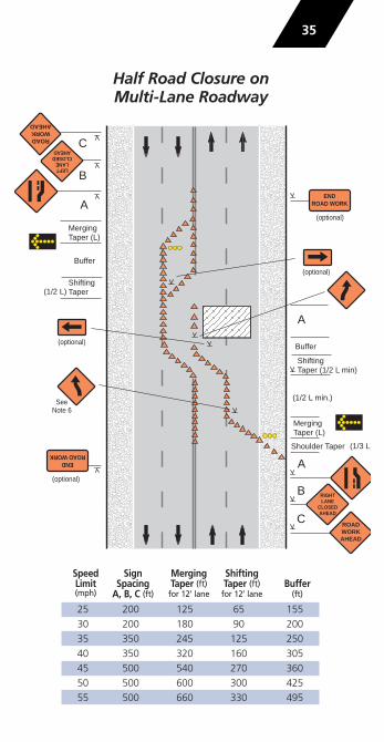
Half Road Closure on Multi-Lane Roadway
35
Buffer
Buffer
ShiftingTaper (1/2 L min)
Merging Taper (L)
ShiftingTaper
Merging Taper (L)
ROADWORKAHEAD
A
A
B
C
ROADWORKAHEAD
C
B
A
RIGHTLANE
CLOSEDAHEAD
LEFTLANE
CLOSEDAHEAD
(optional)
(optional)
(optional)END
ROAD WORK
ENDROAD WORK
(1/2 L)
(1/2 L min.)
(optional)
Shoulder Taper (1/3 L)
SeeNote 6
Speed Sign Merging ShiftingLimit Spacing Taper (ft) Taper (ft) Buffer(mph) A, B, C (ft) for 12’ lane for 12’ lane (ft)
25 200 125 65 155
30 200 180 90 200
35 350 245 125 250
40 350 320 160 305
45 500 540 270 360
50 500 600 300 425
55 500 660 330 495

Half Road Closure on Multi-Lane Roadway
(continued)
Notes
1. Pavement markings no longer applicable shall beremoved or obliterated as soon as practicable. Temporarymarkings shall be used as necessary. For intermediateterm situations when it is not feasible to remove andrestore pavement markings, channelizing devices shall be more closely spaced when the pavement markingsconflict with the temporary travel path. In such locationsa maximum channelizing device spacing in feet of 1⁄ 2 the speed limit in mph should be used.
2. When a side road intersects the roadway within the workzone, additional devices shall be erected to channelizetraffic to/from the side road and a ROAD WORK AHEADsign shall be placed on each side road approach.
3. An arrow board shall be used when a freeway is closed.On other roads an arrow board is optional based on traffic volume, speed, and visibility. Generally, it is a good practice on roads with speeds of 35 mph or greater.
4. If an arrow board is not used, a Large Arrow sign ordirectional indicator barricades in the taper can be usedto provide additional guidance.
5. Large Arrow signs can be used at the shifts for addedvisibility.
6. If the tangent distance along the buffer and work areasis less than 600 feet then the Double Reverse Curve Signmay be used instead of two Reverse Curve/Turn signs.
7. If speeds are 30 mph or less, Reverse Turn signs shall be used instead of Reverse Curve in advance of the shifting tapers.
8. If there is a highway-rail grade crossing near the workarea and backups from the lane closure are anticipatedto extend through the crossing, the temporary trafficcontrol zone should be extended so the taper precedesthe crossing. A flagger may be used at the crossing tominimize the chance of vehicles being stopped on thetracks. (See page 26).
36

Lane Closure in Advance of an Intersection(Work Area on the Through Road)
Notes
1. Depending on traffic conditions, consider additional traffic control on the side road approaches, such as flaggers and appropriate signs.
2. The flaggers shall use approved flagging procedures according to theMUTCD and as shown on page 56.
37
ROAD WORK AHEAD
C
B
A
A
A
ROAD WORK AHEAD
RO
AD
W
OR
K
AH
EA
D
RO
AD
W
OR
K
AH
EA
D
A
C
Buffer 50' MIN
to 100' MAX
Taper
B ONE LANE
ROAD AHEAD
ONE LANE ROAD
AHEAD
Speed SignLimit Spacing Buffer(mph) A, B, C (ft) (ft)
25 200 155
30 200 200
35 350 250
40 350 305
45 500 360
50 500 425
55 500 495

Lane Closure in Advance of an Intersection(Work Area on the Side Road)
Notes1. Depending on traffic conditions, consider additional traffic control,
such as flaggers and appropriate signs.2. The middle flagger has the best view of traffic from all directions and
would normally be lead flagger and coordinate the other flaggers.3. The flaggers shall use approved flagging procedures according to the
MUTCD and as shown on page 56.
38
ONE LANE ROAD
AHEAD
B
A
B
C
RO
AD
W
OR
K
AH
EA
D
RO
AD
W
OR
K
AH
EA
D
A
A
C
A
Buffer 50' MIN
to 100' MAX
Taper
B ONE LANE
ROAD AHEAD
B
ROAD WORK AHEAD
ROAD WORK AHEAD
Speed SignLimit Spacing Buffer(mph) A, B, C (ft) (ft)
25 200 155
30 200 200
35 350 250
40 350 305
45 500 360
50 500 425
55 500 495

Lane Closure Beyond an Intersection(Work Area on the Through Road)
Notes
1. Depending on traffic conditions, consider additional traffic control, such as flaggers and appropriate signs.
2. The flaggers shall use approved flagging procedures according to theMUTCD and as shown on page 56.
39
A
ROAD WORK AHEAD
C
B
A
A
ROAD WORK AHEAD
RO
AD
W
OR
K
AH
EA
D
RO
AD
W
OR
K
AH
EA
D
A
C
Buffer
100'
50' MIN to
100' MAX
200' to 300'
Taper
B ONE LANE
ROAD AHEAD
ONE LANE ROAD
AHEAD
Speed SignLimit Spacing Buffer(mph) A, B, C (ft) (ft)
25 200 155
30 200 200
35 350 250
40 350 305
45 500 360
50 500 425
55 500 495

Lane Closure Beyond an Intersection(Work Area on the Side Road)
Notes
1. Depending on traffic conditions, consider additional traffic control, such as flaggers and appropriate signs.
2. The middle flagger would normally be lead flagger and would coordinate the other flaggers.
3. The flaggers shall use approved flagging procedures according to the MUTCD and as shown on page 56.
40
B R
OA
D
WO
RK
A
HE
AD
A
ROAD WORK AHEAD
C
B
A
ROAD WORK AHEAD
A
C
Buffer
100'
50' MIN to
100' MAX Taper
B ONE LANE
ROAD AHEAD
ONE LANE ROAD
AHEAD
A
RO
AD
W
OR
K
AH
EA
D
B
200' to 300'
Speed SignLimit Spacing Buffer(mph) A, B, C (ft) (ft)
25 200 155
30 200 200
35 350 250
40 350 305
45 500 360
50 500 425
55 500 495

Lane Closure on Far Side of Intersection(Speeds of 35 mph or Less)
Notes
1. This layout is only appropriate forroads with speeds of 35 mph or less.For higher speeds, see page 31 foradvance signing and taper layout.
2. Normal procedure is to close any lane that is not carried through theintersection on the near side of the intersection. However, if this results in the closure of a lane having significant turning movements, then that lane may be converted to a turn bay, and/or the lane may be restricted to turns only, as shown.
3. A Large Arrow sign or Arrow Board could be used instead of the Keep Right or Down Arrow sign where space permits.
41
LEFT TURN LANE
A
50' to 100'
Merging Taper (L)
(1/2 L)
ROAD WORK AHEAD
AB
LEFTLANE
CLOSEDAHEAD
A
RO
AD
W
OR
K
AH
EA
D
ROAD WORK AHEAD
A
END ROAD WORK
(optional)
EN
D
RO
AD
WO
RK
(optional)
END ROAD WORK
EN
D
RO
AD
WO
RK
(optional)
(optional)RO
AD
W
OR
K
AH
EA
D
OR
OR
LEFT LANE MUST
TURN LEFT
Speed Sign MergingLimit Spacing (ft) Taper (ft)(mph) A B for 12’ lane
25 200 200 125
30 200 200 180
35 350 350 245

Closure in the Center of an Intersection
Notes
1. Consider additional advancewarning signs such as ROADNARROWS or Reverse Curve/Turn. The Reverse Curve/Turn sign is appropriate forlarger deviations in the travel path.
2. Left turns may be prohibitedas required by traffic condi-tions. Unless the streets arewide, it may be physicallyimpossible to turn left, especially for large vehicles.
3. For short duration work (60 minutes or less), the channelizing devicesmay be eliminated if a vehicle with activated high intensity lights ispositioned in the work space.
42
10'MIN
10'MIN
10'
MIN
10'M
IN
A
RO
AD
W
OR
K
AH
EA
D
ShiftingTaper
ShiftingTaper
ShiftingTaper
ShiftingTaper
A
A
A
(1/2 L)
(1/2 L)
(1/2 L)
(optional)
(1/2 L)
ROAD WORK AHEAD
RO
AD
W
OR
K
AH
EA
D
ROAD WORK AHEAD
OR
OR
Speed Sign ShiftLimit Spacing Taper (ft)(mph) A, B (ft) 5’ shift 10’ shift
25 200 30 55
30 200 40 75
35 350 55 105
40 350 70 135
45 500 115 225
50 500 125 250
55 500 140 275

Street Closure with Detour
Notes
1. This layout should be used for streets and roadswithout posted route numbers. See figure 6H-8and 6H-9 of the MUTCD Part 6 for closing anddetouring a numbered highway.
2. When a side road intersects the roadway withinthe work zone, place Type III barricades andROAD CLOSED signs at the intersections, andprovide advance signing of the closure on the side road approaches.
3. A street name sign may be mounted with the DETOUR sign and should be used if a local road is detoured onto a state highway. If used, the street nameplate goes above the DETOUR sign.
4. A DETOUR sign with an advance turn arrow may be used in advance of a turn and should be used on multilane streets.
5. DETOUR signs may be located on the far side of intersections.
43
A
A
B
B
ROAD CLOSED AHEAD
ROAD CLOSED AHEAD
DETOUR AHEAD
DETOUR AHEAD
(optional)
(optional)
END DETOUR
END DETOUR
MA
IN S
T.
DE
TOU
R
MA
IN S
T.
DE
TOU
R
MA
IN S
T.
DE
TOU
R
MA
IN S
T.
DE
TOU
R
MAIN ST.
DETOUR
MAIN ST.
DETOUR
DETOUR
DETOUR
ROAD CLOSED TO
THRU TRAFFIC
ROAD CLOSED
ROAD CLOSED
Speed SignLimit Spacing(mph) A, B (ft)
25-30 200
35-40 350
45-50 500

Mobile OperationsMobile operations are work activities that move along theroad either intermittently or continuously. Safety for mobileoperations should not be compromised by using fewerdevices simply because the operation will frequently changeits location.
Mobile devices can be used. For example, appropriately colored or marked vehicles with activated high intensity lights,perhaps augmented with signs or arrow boards, may be used in place of stationary signs and channelizing devices.
For mobile operations to be successful, the advance warning area should move with the work area or be repositioned periodically to be near the mobile work area.
Flaggers may be used. They shall use approved flagging procedures according to the MUTCD and as shown onpage 56.
When volumes and/or speeds are high, a shadow vehicle,equipped with an arrow board or sign, should follow thework vehicle. In addition, vehicles may be equipped withtruck-mounted attenuators and/or portable, changeable message signs. If traffic volumes are high, considerationshould be given to doing the work during off-peak hours.
Intermittent Mobile Operations – These mobile operationsoften involve frequent short stops for activities such as littercleanup, pothole patching, or utility operations and are similar to short-duration operations. Warning signs, activatedhigh intensity lights, and/or channelizing devices should beused and moved periodically.
Continuously Moving Mobile Operations – These mobile operations include work activities in which workersand equipment move along the road without stopping, (e.g. pavement striping, mowing, street sweeping, or herbicide spraying), usually at slow speeds.
With operations that move slowly (less than 3 mph),mobile or stationary signs that are periodically repositioned in the advance warning area may be used. For mobile operations that move at speeds greater than 20 mph, vehicles shall have appropriate activated high intensity lights,signs, and/or special lighting.
For some continuously moving operations where volumes are low and visibility is good, a single work vehiclewith appropriate warning devices on the vehicle may suffice.
44

Mobile Operation on the Shoulder
45
5 milesmaximum
ROAD WORK AHEAD
SHOULDER WORK
NEXT X MILES
See Note 4
(optional)
or or
(See Notes 3 and 4)
Truck MountedAttenuator (optional)See Note 7 on page 46.
Work Vehicle

Mobile Operation on the Shoulder (continued)
Notes
1. If the operation requires encroachment on the travelway, use a mobile or stationary lane closure, unless a 10-footminimum lane width is maintained and the volume is lessthan 1500 ADT.
2. For operations that move less than 3 mph or where multiple work locations in a limited distance make it practical to place stationary signs, the distance from the advance warning sign to the work area should notexceed 5 miles.
3. The ROADWORK NEXT X MILES sign or a supplementalplaque (NEXT X MILES) may be used for work zones more than 2 miles long.
4. A shadow vehicle equipped with a SHOULDER WORK sign,optional Truck Mounted Attenuator and Arrow Board ( in Caution mode) may be used, depending on availabilityand type of operation. Its use is recommended on high-volume roads, or roads with poor sight distance. If used, it is located behind the work vehicle to provide advancewarning. If the shadow vehicle with sign is used, the stationary sign can be omitted.
5. Warning signs may be omitted if the work vehicle displaysactivated high intensity lights.
6. Other acceptable advance warning signs include UTILITYWORK AHEAD, SHOULDER WORK, MOWING, Workers, and ROAD MACHINERY AHEAD.
7. The table below gives recommended roll-ahead distancesbetween a vehicle with a truck-mounted attenuator (TMA) and the work area for both stationary and mobile operations. The roll-ahead distance for the vehicle could vary depend ing upon the recom mendations of the TMA manufacturer.
46
Roll-ahead Distances for TMAs
Speed Stationary Mobile
≤45 mph 100 ft 150 ft
50-55 mph 150 ft 200 ft
60-65 mph 200 ft 275 ft

Mobile Operation on a Two-Lane Road
47
5 milesmaximum
ONE LANE ROAD
Truck MountedAttenuator
(recommended)See Note 7 on page 46
ROAD WORK AHEAD
ROAD WORK AHEAD
ONE LANE
ROAD OR
NEXT X MILES
See Notes 7 and 8(optional)
Truck MountedAttenuator
(optional)See Note 7 on page 46.
or or

Mobile Operation on a Two-Lane Road (continued)
Notes
1. The work and shadow vehicles should pull over periodically to allowtraffic to pass. If this cannot be done frequently, a do not pass signmay be placed on the rear of the vehicle blocking the lane.
2. Shadow vehicles are used to warn traffic of the operation ahead. Thedistance between the work and shadow vehicles may vary accordingto terrain, paint drying time, and other factors. Whenever adequatestopping sight distance exists to the rear, the shadow vehicle shouldmaintain the minimum distance and proceed at the same speed as the work vehicle. The shadow vehicle should slow down in advance of vertical or horizontal curves that restrict sight distance.
3. Additional shadow vehicles to warn and reduce the speed of on-coming or opposing traffic may be used. Police patrol cars may beused for this purpose.
4. Shadow and work vehicles shall display activated high intensity lights.Shadow vehicles should also display two high-intensity flashing lightsmounted on the rear, adjacent to the sign.
5. Vehicle-mounted signs shall be mounted so as to not be obstructed by equipment or supplies and to provide an unobstructed view of vehicle lights or arrow board. Sign legends shall be covered orturned from view when work is not in progress.
6. The shadow vehicle may not be needed for roadways with volume less than 1500 ADT, especially if sight distance is good. For higher volume conditions the shadow vehicle should be used.
7. Stationary advance warning signs similar to that on the shadow vehicle can be used to provide additional advance warning. Thesesigns might include: SLOW MOVING TRAFFIC, ROAD WORK AHEAD,PAINT CREW AHEAD, SURVEY CREW AHEAD etc. Consider using thesesigns where speed and/or volumes are high, where sight distance islimited, or if a shadow vehicle is not used. If stationary signs are notused, use a ROAD WORK AHEAD sign on the shadow vehicle.
8. If stationary signs are used and the work zone is more than 2 mileslong, the ROAD WORK NEXT X MILES sign or a supplemental plaqueshould be used.
48

49
Mobile Operation on aTwo-Lane Road Using Flaggers
(Traveling at less than 3 mph)
CB
200'
ROAD WORK AHEAD
BE PREPARED
TO STOP A (min.) to3500' (max.)
A (min.) to3500' (max.)
BC
200'
Appr
oxim
ately
2 m
iles
ROAD WORK AHEAD
ONE LANE ROAD
AHEAD
(Optional)
(Optional)BE
PREPARED TO STOP
ONE LANE ROAD
AHEAD
Truck MountedAttenuator (optional)See Note 7 on page 46.
Speed SignLimit Spacing(mph) A, B, C (ft)
25-30 200
35-40 350
45-55 500

Mobile Operation on aTwo-Lane Road Using Flaggers(Traveling at less than 3 mph)
(continued)
Notes
1. Do not exceed 2 miles for the total length of the temporary traffic control zone.
2. Where feasible, use well defined end points (e.g. majordriveways, inter sections, city limits, etc.) to establish thelimits of the work zone.
3. Flagger warning signs should be repositioned periodicallyas the operation moves.
4. Suggested shadow vehicle configuration includes activated high intensity lights and a truck mounted attenuator.
5. If there is a sideroad intersection within the work area,provide ROAD WORK AHEAD signs and consider additionaltraffic control, such as flaggers and other appropriatesigns on the sideroad approaches.
6. Flaggers shall use approved flagging procedures accordingto the MUTCD and as shown on page 56.
50
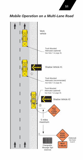
Mobile Operation on a Multi-Lane Road
51
5 milesmaximum
Changeable Message Sign
(Optional)
ROAD WORK AHEAD (Optional)
See Notes8 and 9
NEXT X MILES
1
2
RIGHTLANE
CLOSEDAHEAD
Truck MountedAttenuator (optional)See Note 7 on page 46.
Truck MountedAttenuator (recommended)See Note 7 on page 46.
Truck MountedAttenuator (optional)See Note 7 on page 46.
Shadow Vehicle #2
Shadow Vehicle #1
Workvehicle

Mobile Operation on aMulti-Lane Road (continued)
Notes
1. Vehicles used for these operations should be made highly visible with appropriate equipment, such as activated high intensity lights, flags, signs, or arrow boards.
2. Shadow vehicle #1 should be equipped with an arrowboard and truck mounted attenuator.
3. Shadow vehicle #2 should be equipped with an arrow board and may be equipped with a truck mountedattenuator. An appropriate lane closure sign should beplaced on shadow vehicle #2 so as not to obscure thearrow board.
4. On high-speed roadways, a third shadow vehicle (not shown) may be used with shadow vehicle #1 in the closed lane, shadow vehicle #2 straddling theedge line, and shadow vehicle #3 on the shoulder.
5. When adequate shoulder width is not available, the rear shadow vehicle may drive partially in the lane.
6. Shadow vehicles should travel at a varying distance from the work operation so as to provide adequatesight distance for traffic approaching from the rear.
7. Spacing between vehicles should be minimized to deter traffic from driving in between the convoy of vehicles.
8. Stationary advance warning signs can be used to provide additional advance warning. These signs mightinclude: SLOW MOVING TRAFFIC AHEAD, ROAD WORKAHEAD, PAINT CREW AHEAD, etc. Consider using thesesigns and/or a changeable message sign where speedsand volumes are high, where sight distance is limited, or if shadow vehicle #2 is not used.
9. If stationary signs are used and the work zone is morethan 2 miles long, a ROAD WORK NEXT X MILES sign orsupplemental plaque should be used.
10. Work should normally be done during off-peak hours.
52

Pedestrian and Bicyclist Safety
It is important to provide continuous access for pedestrians,bicyclists, and to bus stops. If pedestrian or bicycle travelpaths are closed or disrupted by con struction, maintenance,or utility operations, traffic control is needed. This includesusing signs, channelizing devices, etc. to direct pedestriansand bicyclists through or around the work site, or to alternateroutes. Major considerations in planning for pedestrian andbicyclist safety are:
� Do not lead pedestrians or bicyclists into conflicts withwork site vehicles, equipment, or operations, nor trafficmoving through or around the work site. Obstructionsshould be clearly marked, especially at night.
� Do not block or relocate pedestrian or bicycle routes fornon-construction activities such as parking for vehicles and equipment.
� Provide pedestrians with a safe, convenient and clearlydelineated travel path that replicates as nearly as practicalthe most desirable characteristics of existing sidewalks or footpaths. Signals and devices mounted lower than 7 feet should not project more than 4 inches into pedestrian facilities.
� Where sidewalks are closed or relocated, provisions shallbe made for disabled pedestrians. When it is determineda facility should be accessible to pedestrians with visual disabilities, continuously detectable edging should be provided for pedestrians using long canes for guidance.Examples include interconnected barrier, curb, lumber, orfencing with a continuous bottom rail. If channelizingdevices are used there cannot be gaps between the bases.Audible devices should be considered to provide commu-nication of closings and crosswalk changes to pedestrianswith visual disabilities. Audible devices might not be needed if detectable channelization makes an alternateroute of travel evident to persons with visual disabilities.
� Advance notification of sidewalk closures shall be providedto the maintaining agency.
53

Sidewalk Closure(Pedestrian Detour)
Notes
1. Additional advance warning may be necessary.2. Only the traffic control devices related to pedestrians are shown.
Other devices may be needed to control traffic on the streets such as lane closure signs, ROAD NARROWS or LANE NARROWS signs.
3. For nighttime closures, Type A flashing warning lights may be usedon barricades supporting signs and closing walkways.
4. Audible devices should be considered to alert pedestrians with visual disabilities of closings and crosswalk changes.
54
ROAD WORK AHEAD
SIDEWALK CLOSED
USE OTHER SIDE
SIDEWALK CLOSED
USE OTHER SIDE
SIDEWALK CLOSED
(optional)

Sidewalk Closure(Pedestrian Walkway Provided)
Notes
1. Additional advance warning may be necessary.2. Only the traffic control devices related to pedestrians are shown. Other
devices such as lane closure signs, ROAD NARROWS or LANE NARROWSsigns may be needed to control traffic on the streets.
3. For nighttime closures, Type A flashing warning lights may be used onbarricades supporting signs and closing walkways. Type C or Type Dsteady-burn lights may be used on channelizing devices separating thetemporary walkway from vehicular traffic.
4. Where high speeds are likely, a barrier should separate the temporary walkway from vehicular traffic. Refer to Section 6D.01of Part 6 of theMUTCD for information on barriers.
5. Signs may be placed along a temporary walkway to guide pedestrians; for example, Keep Right or Keep Left signs.
55
ROAD WORK AHEAD
36 inch minimumwidth walkway
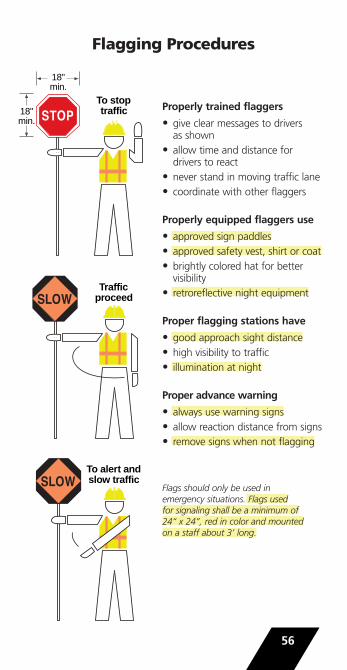
Flagging Procedures
56
To alert andslow traffic
To stoptraffic
18"min.
Trafficproceed
18"min.
Properly trained flaggers
• give clear messages to driversas shown
• allow time and distance fordrivers to react
• never stand in moving traffic lane• coordinate with other flaggers
Properly equipped flaggers use
• approved sign paddles• approved safety vest, shirt or coat• brightly colored hat for bettervisibility
• retroreflective night equipment
Proper flagging stations have
• good approach sight distance• high visibility to traffic• illumination at night
Proper advance warning
• always use warning signs• allow reaction distance from signs• remove signs when not flagging
Flags should only be used in emergency situations. Flags used for signaling shall be a minimum of24“ x 24”, red in color and mountedon a staff about 3’ long.
Worker SafetyThe safety of workers in a work site is just as important as thesafety of the public traveling through the work zone. The bestprotection for both is good work zone traffic control.
All workers should be trained in how to work next to traffic ina way that minimizes their vulnerability. In addition, workerswith specific traffic control responsibilities should be trained intraffic control techniques, device usage, and placement.
Workers close to traffic or construction equipment should wearbright, highly visible apparel meeting the requirements of ANSI107-2004 standard for reflectivity and background material.Flaggers shall wear safety apparel meeting the requirements ofANSI 107-2004 Class 2 or 3. For nighttime work, apparelmeeting ANSI 107-2004 Class 3 (including high-visibility pants)should be considered for flaggers.
These garments shall be either fluorescent orange-red or fluorescent yellow-green. The retroreflective material shall be orange, yellow, white, silver, or yellow-green, or a fluorescent version of these colors, and shall be visible at a minimum distance of 1000 feet. The safety apparel shall be designed to clearly identify the wearer as a person (i.e. retroflective materialon the front, back, and both sides of the garment). Other spe-cific agency requirements for garments can also apply, such asOSHA requirements for private sector employees and WisDOTSafety Directives for WisDOT employees.
A competent person designated by the employer should assesshazards at the work site and determine whether protectivemeasures should be implemented. Planning the internal workactivity area to minimize backing maneuvers of work vehiclesshould be considered to minimize the risk to workers on foot.
Supervisor‘s Checklist1. Follow Part 6 and the Wisconsin Supplement of the
Manual on Uniform Traffic Control Devices.
2. Have a traffic control plan before going to the work site.
3. Ask yourself, “What is the driver‘s view of the work site—at night, during peak hours, etc.”
4. Investigate crashes/incidents to identify if changes are needed in the traffic control plan.
57

Liability
Steps to Minimize Liability
• have a current traffic control plan• apply the concepts of the MUTCD (Manual on Uniform Traffic
Control Devices)• minimize traffic disruptions• promptly remove or add devices as necessary• train all personnel• inspect work zone sites regularly for conformance andchanging conditions
• maintain good documentation
Elements of a Good Inspection Program
• routinely conduct inspections at different times of day/evening• identify hazards and take corrective action• record observations and actions taken• verify corrective actions• update documentation
Minimum Documentation
• who was on the site and when• where was the work taking place• when were traffic control devices inspected, by whom• record any irregularities, action taken and follow up inspection• gather additional information in the event of a crash
AcknowledgmentsPrevious pocket-guide editions were adapted for use in Wisconsin by theWisconsin Department of Transportation (WisDOT) and the WisconsinTranspor tation Information Center (TIC) from the one produced by theInstitute for Transportation Research and Education (ITRE) at NorthCarolina State University. This new edition includes changes contained in the 2009 MUTCD and the 2011 Wisconsin Supplement.
The Wisconsin team that produced this edition included representativesof the construction, maintenance, and traffic sections of WisDOT; theFederal Highway Administration, Wisconsin Division; TIC workzone training instructors; and the University of Wisconsin-MadisonTransportation Information Center.
NAME _______________________________________________
58

Information and TrainingFor information, copies of this pocket guide, and trainingopportunities in work zone traffic control, flagging, or otherstreet and highway design, operation and maintenance topics,contact the Wisconsin Transportation Information Center, aproject of the University of Wisconsin-Madison Department of Engineering Professional Develop ment, funded as a LocalTranspor tation Assistance Program by the Federal HighwayAdministration, Wisconsin Department of Transportation, and UW-Extension.
Transportation Information Center – LTAPUniversity of Wisconsin-Madison432 N. Lake Street Madison, WI 53706800-442-4615608-263-3160 faxemail: [email protected] site: http://tic.engr.wisc.edu/
Transportation Information Center – LTAPUniversity of Wisconsin –Madison
WZ13cover_WZ cover03 (WI) 2/28/13 2:56 PM Page 2


