132
Transmission External ZF training Page | 1 Workbook Transmission Technology
Transmission External ZF training
P a g e | 1
Workbook
Transmission Technology
Transmission External ZF training
P a g e | 2
Table of content
1. Transmission History ..................................................................................... 3
2. 6HP Design .................................................................................................... 4
3. Adaption ..................................................................................................... 25
3. Oil change Service and Mechatronic ........................................................... 38
4. 6HP Overhaul .............................................................................................. 60
6. 8 HP Transmission ....................................................................................... 80
7. Identification of the Transmission ............................................................... 85
8. Troubleshooting ........................................................................................ 113
Transmission External ZF training
P a g e | 3
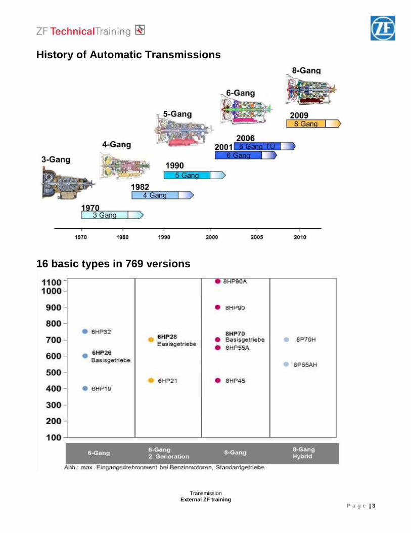
History of Automatic Transmissions
16 basic types in 769 versions
Transmission External ZF training
P a g e | 4
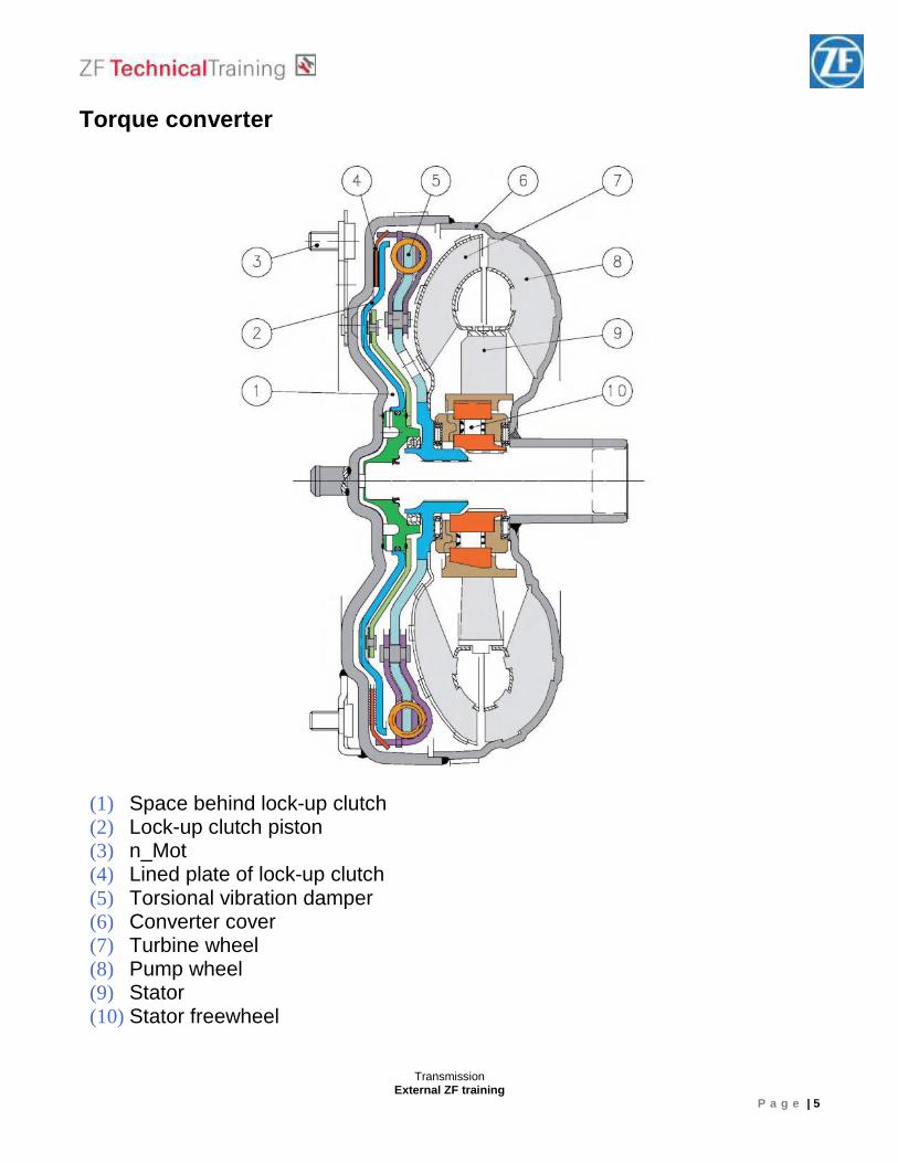
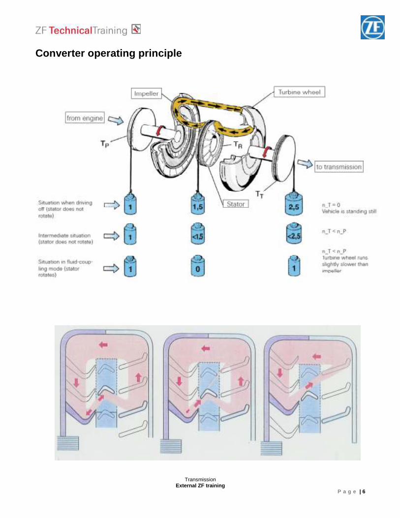
The hydrodynamic torque converter Converter operating principle The torque converter consists of the impeller, the turbine wheel, the reaction element (stator) and the oil content needed to transmit the torque. The impeller, which is driven by the engine, imparts a circular flow of the oil in the converter. This oil strikes the turbine wheel, which causes the flow to change its direction. The oil flows out of the turbine wheel close to the hub and strikes the stator, where its direction is changed again to a direction for re-entering the impeller. The change in direction at the stator generates a torque reaction that increases the torque reaching the turbine. The ratio between the turbine and the impeller torque is referred to as torque multiplication or conversion. The greater the difference in speeds of rotation at the impeller and the turbine, the greater the increase in torque. The maximum increase is obtained when the turbine wheel is stationary. As turbine wheel speed increases, the amount of torque multiplication gradually drops. When the turbine wheel is rotating at about 85% of the impeller speed, torque conversion reverts to 1. That is to say torque at the turbine wheel is no higher than at the impeller. The stator, which is prevented from rotating backwards by a freewheel and the shaft in the gearbox housing, runs freely in the oil and overruns the freewheel. From this point on, the converter acts only as a fluid coupling. During the torque conversion process, the stator ceases to rotate and bears against the housing via the freewheel.
Transmission External ZF training
P a g e | 5
Torque converter
(1) Space behind lock-up clutch (2) Lock-up clutch piston (3) n_Mot (4) Lined plate of lock-up clutch (5) Torsional vibration damper (6) Converter cover (7) Turbine wheel (8) Pump wheel (9) Stator (10) Stator freewheel
Transmission External ZF training
P a g e | 6
Converter operating principle
Transmission External ZF training
P a g e | 7
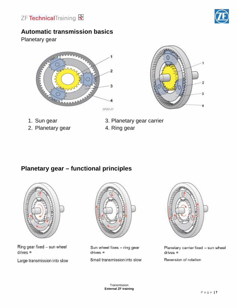
Automatic transmission basics Planetary gear
1. Sun gear 3. Planetary gear carrier 2. Planetary gear 4. Ring gear
Planetary gear – functional principles
Transmission External ZF training
P a g e | 8
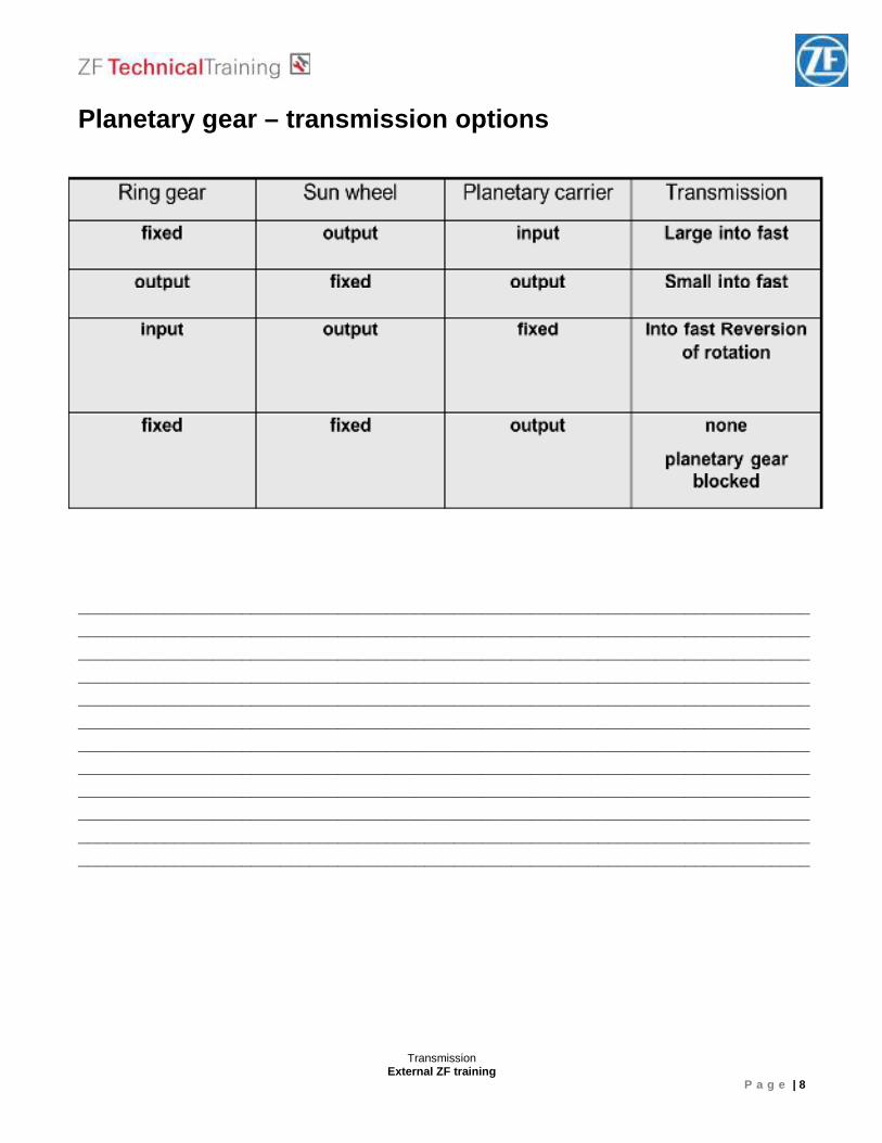
Planetary gear – transmission options ________________________________________________________________________________________________________________________________________________________________________________________________________________________________________________________________________________________________________________ ________________________________________________________________________________________________________________________________________________________________________________________________________________________________________________________________________________________________________________ ________________________________________________________________________________________________________________________________________________________________________________________________________________________________________________________________________________________________________________
Transmission External ZF training
P a g e | 9
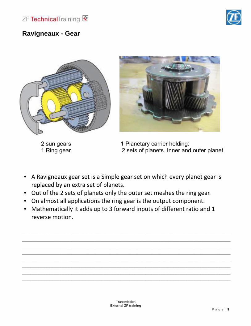
Ravigneaux - Gear ____________________________________________________________________________ ________________________________________________________________________________________________________________________________________________________________________________________________________________________________________________________________________________________________________________ ____________________________________________________________________________ ________________________________________________________________________________________________________________________________________________________
2 sun gears 1 Planetary carrier holding: 1 Ring gear 2 sets of planets. Inner and outer planet
• A Ravigneaux gear set is a Simple gear set on which every planet gear is
replaced by an extra set of planets. • Out of the 2 sets of planets only the outer set meshes the ring gear. • On almost all applications the ring gear is the output component. • Mathematically it adds up to 3 forward inputs of different ratio and 1
reverse motion.
Transmission External ZF training
P a g e | 10
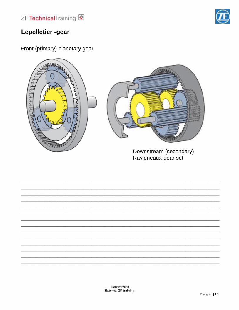
Lepelletier -gear
____________________________________________________________________________ ________________________________________________________________________________________________________________________________________________________________________________________________________________________________________________________________________________________________________________ ____________________________________________________________________________ ________________________________________________________________________________________________________________________________________________________ ____________________________________________________________________________ ________________________________________________________________________________________________________________________________________________________________________________________________________________________________________________________________________________________________________________ ____________________________________________________________________________
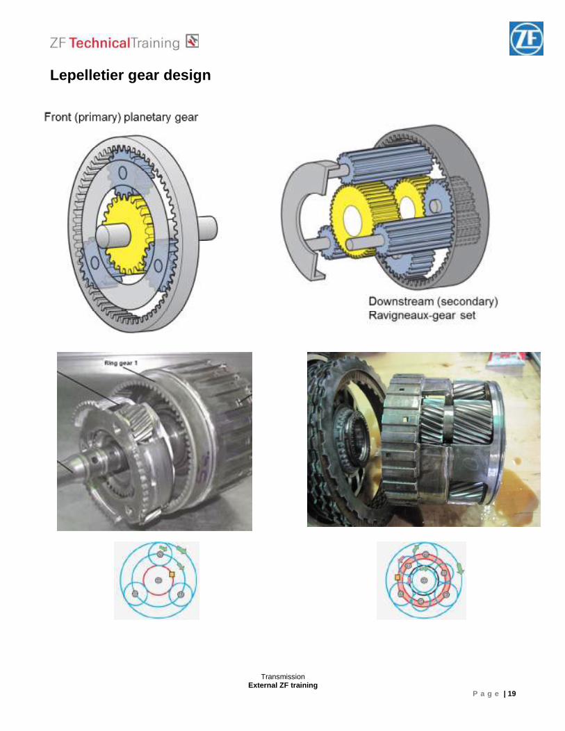
Front (primary) planetary gear
Downstream (secondary) Ravigneaux-gear set
Transmission External ZF training
P a g e | 11
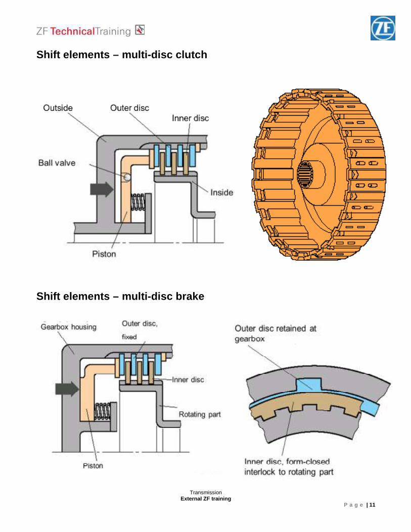
Shift elements – multi-disc clutch
Shift elements – multi-disc brake
Transmission External ZF training
P a g e | 12
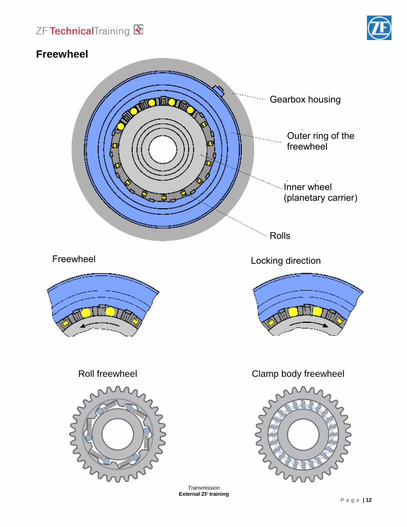
Freewheel
Roll freewheel Clamp body freewheel
Freewheel Locking direction
Gearbox housing
Outer ring of the freewheel
Inner wheel (planetary carrier)
Rolls
Transmission External ZF training
P a g e | 13
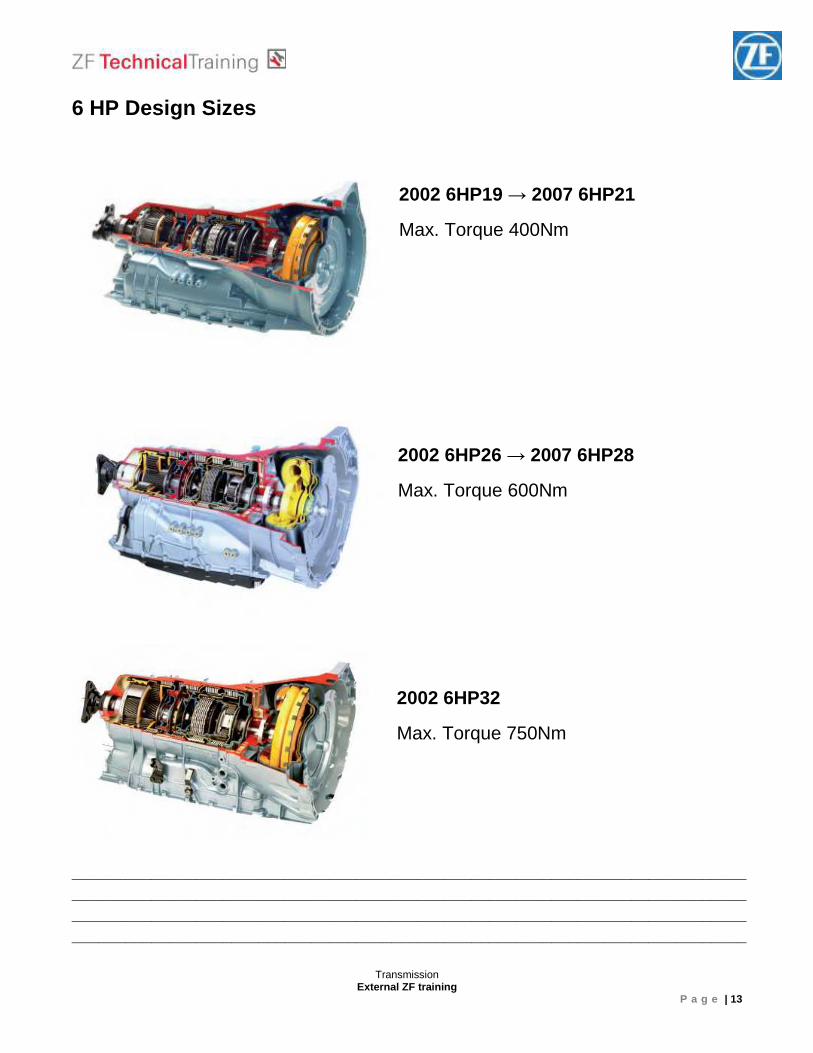
6 HP Design Sizes
2002 6HP19 → 2007 6HP21
Max. Torque 400Nm
2002 6HP26 → 2007 6HP28
Max. Torque 600Nm
2002 6HP32
Max. Torque 750Nm
________________________________________________________________________________________________________________________________________________________________________________________________________________________________________________________________________________________________________________
Transmission External ZF training
P a g e | 14
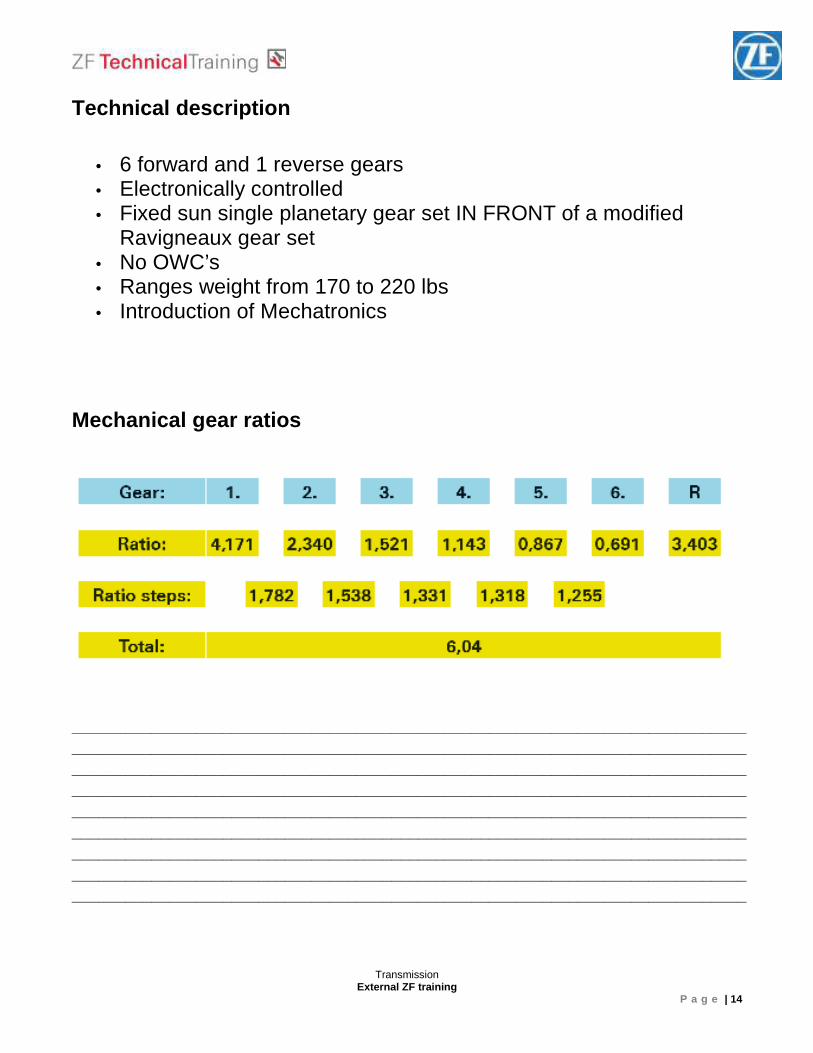
Technical description
• 6 forward and 1 reverse gears
• Electronically controlled
• Fixed sun single planetary gear set IN FRONT of a modified Ravigneaux gear set
• No OWC’s
• Ranges weight from 170 to 220 lbs
• Introduction of Mechatronics
Mechanical gear ratios
____________________________________________________________________________ ________________________________________________________________________________________________________________________________________________________ ____________________________________________________________________________ ________________________________________________________________________________________________________________________________________________________________________________________________________________________________________________________________________________________________________________ ____________________________________________________________________________
Transmission External ZF training
P a g e | 15
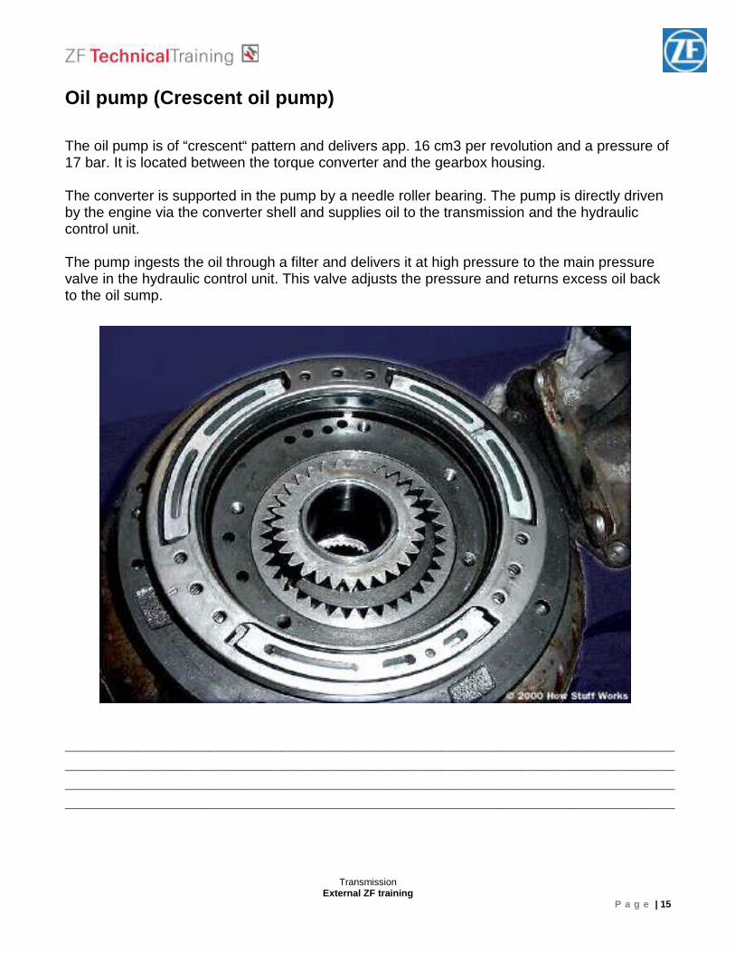
Oil pump (Crescent oil pump) The oil pump is of “crescent“ pattern and delivers app. 16 cm3 per revolution and a pressure of 17 bar. It is located between the torque converter and the gearbox housing. The converter is supported in the pump by a needle roller bearing. The pump is directly driven by the engine via the converter shell and supplies oil to the transmission and the hydraulic control unit. The pump ingests the oil through a filter and delivers it at high pressure to the main pressure valve in the hydraulic control unit. This valve adjusts the pressure and returns excess oil back to the oil sump.
________________________________________________________________________________________________________________________________________________________________________________________________________________________________________________________________________________________________________________
Transmission External ZF training
P a g e | 16
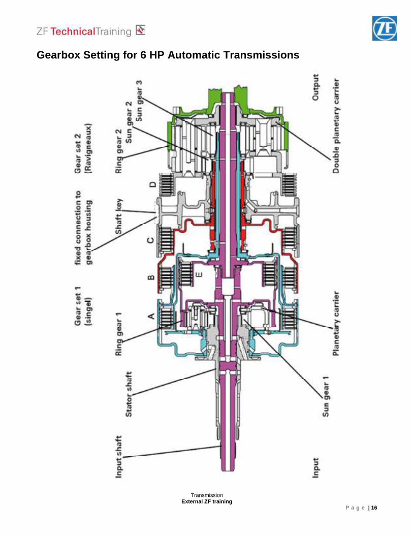
Gearbox Setting for 6 HP Automatic Transmissions
Transmission External ZF training
P a g e | 17
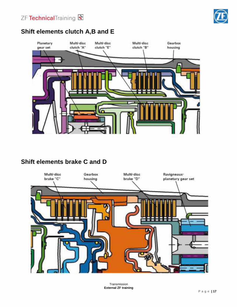
Shift elements clutch A,B and E Shift elements brake C and D
Transmission External ZF training
P a g e | 18
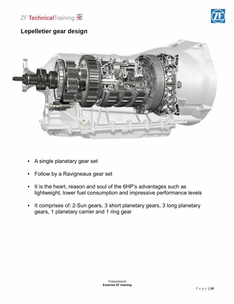
Lepelletier gear design
• A single planetary gear set
• Follow by a Ravigneaux gear set
• It is the heart, reason and soul of the 6HP’s advantages such as lightweight, lower fuel consumption and impressive performance levels
• It comprises of: 2-Sun gears, 3 short planetary gears, 3 long planetary gears, 1 planetary carrier and 1 ring gear
Transmission External ZF training
P a g e | 19
Lepelletier gear design
Transmission External ZF training
P a g e | 20
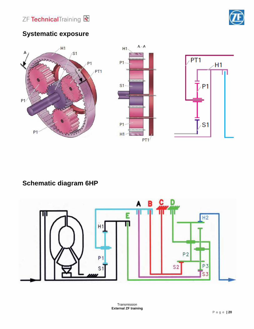
Systematic exposure
Schematic diagram 6HP
Transmission External ZF training
P a g e | 21
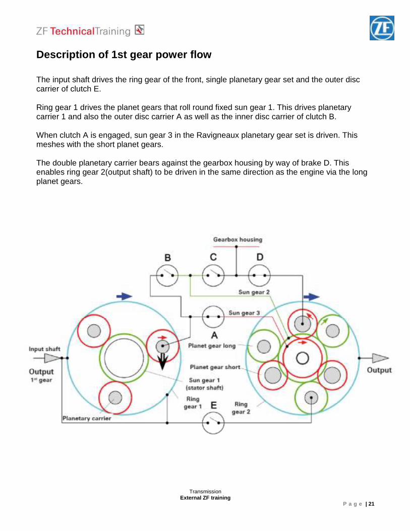
Description of 1st gear power flow The input shaft drives the ring gear of the front, single planetary gear set and the outer disc carrier of clutch E. Ring gear 1 drives the planet gears that roll round fixed sun gear 1. This drives planetary carrier 1 and also the outer disc carrier A as well as the inner disc carrier of clutch B. When clutch A is engaged, sun gear 3 in the Ravigneaux planetary gear set is driven. This meshes with the short planet gears. The double planetary carrier bears against the gearbox housing by way of brake D. This enables ring gear 2(output shaft) to be driven in the same direction as the engine via the long planet gears.
Transmission External ZF training
P a g e | 22
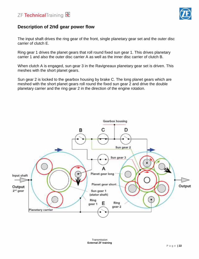
Description of 2 nd gear power flow The input shaft drives the ring gear of the front, single planetary gear set and the outer disc carrier of clutch E. Ring gear 1 drives the planet gears that roll round fixed sun gear 1. This drives planetary carrier 1 and also the outer disc carrier A as well as the inner disc carrier of clutch B. When clutch A is engaged, sun gear 3 in the Ravigneaux planetary gear set is driven. This meshes with the short planet gears. Sun gear 2 is locked to the gearbox housing by brake C. The long planet gears which are meshed with the short planet gears roll round the fixed sun gear 2 and drive the double planetary carrier and the ring gear 2 in the direction of the engine rotation.
Transmission External ZF training
P a g e | 23
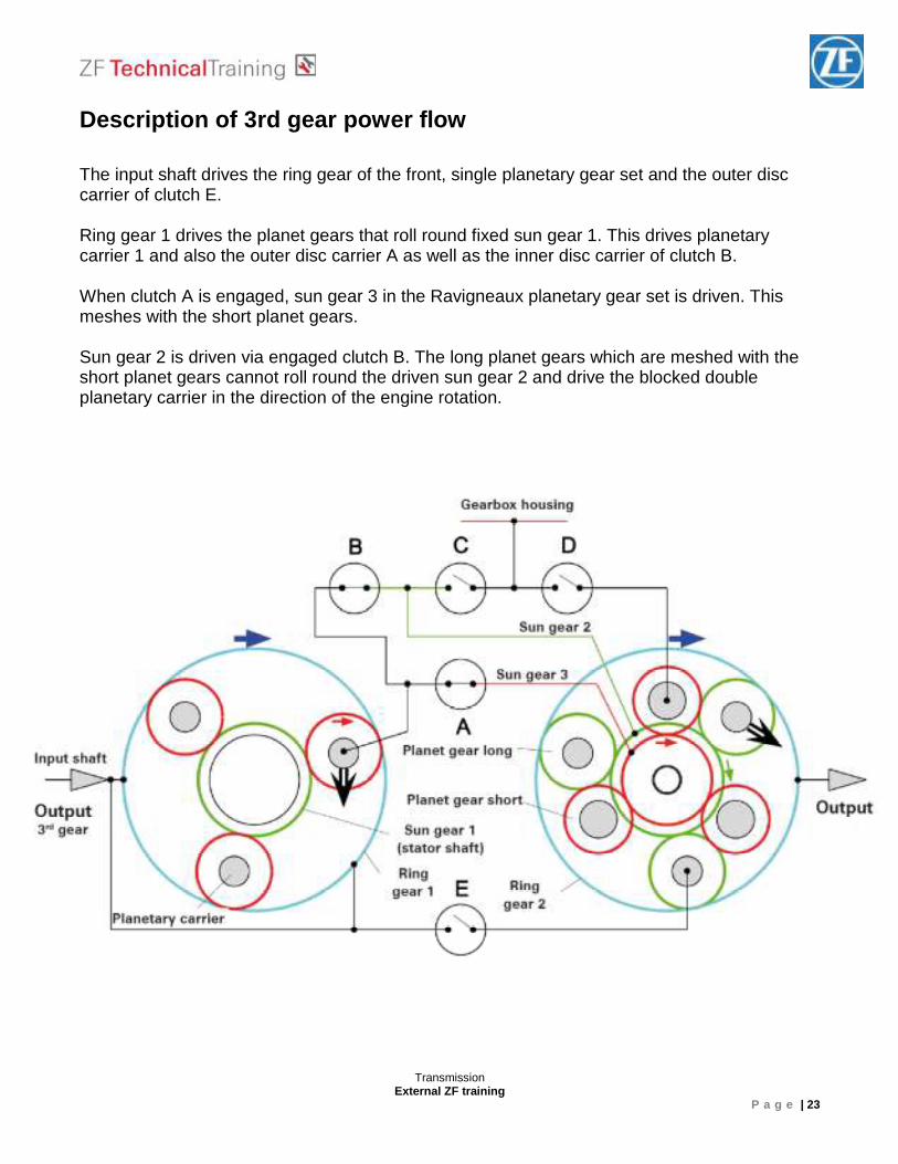
Description of 3rd gear power flow The input shaft drives the ring gear of the front, single planetary gear set and the outer disc carrier of clutch E. Ring gear 1 drives the planet gears that roll round fixed sun gear 1. This drives planetary carrier 1 and also the outer disc carrier A as well as the inner disc carrier of clutch B. When clutch A is engaged, sun gear 3 in the Ravigneaux planetary gear set is driven. This meshes with the short planet gears. Sun gear 2 is driven via engaged clutch B. The long planet gears which are meshed with the short planet gears cannot roll round the driven sun gear 2 and drive the blocked double planetary carrier in the direction of the engine rotation.
Transmission External ZF training
P a g e | 24
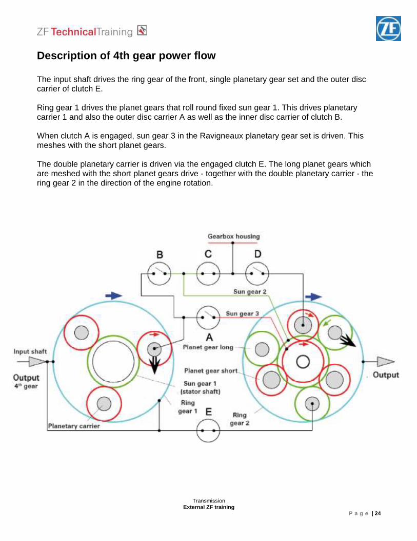
Description of 4th gear power flow The input shaft drives the ring gear of the front, single planetary gear set and the outer disc carrier of clutch E. Ring gear 1 drives the planet gears that roll round fixed sun gear 1. This drives planetary carrier 1 and also the outer disc carrier A as well as the inner disc carrier of clutch B. When clutch A is engaged, sun gear 3 in the Ravigneaux planetary gear set is driven. This meshes with the short planet gears. The double planetary carrier is driven via the engaged clutch E. The long planet gears which are meshed with the short planet gears drive - together with the double planetary carrier - the ring gear 2 in the direction of the engine rotation.
Transmission External ZF training
P a g e | 25
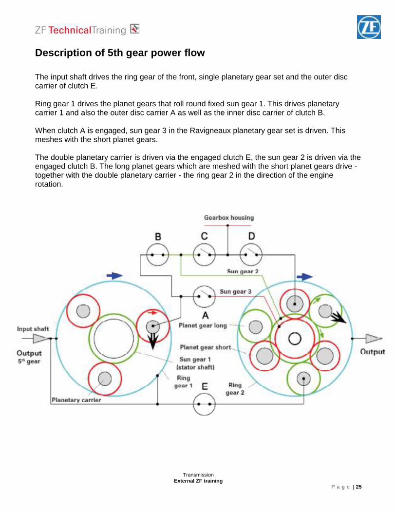
Description of 5th gear power flow The input shaft drives the ring gear of the front, single planetary gear set and the outer disc carrier of clutch E. Ring gear 1 drives the planet gears that roll round fixed sun gear 1. This drives planetary carrier 1 and also the outer disc carrier A as well as the inner disc carrier of clutch B. When clutch A is engaged, sun gear 3 in the Ravigneaux planetary gear set is driven. This meshes with the short planet gears. The double planetary carrier is driven via the engaged clutch E, the sun gear 2 is driven via the engaged clutch B. The long planet gears which are meshed with the short planet gears drive - together with the double planetary carrier - the ring gear 2 in the direction of the engine rotation.
Transmission External ZF training
P a g e | 26
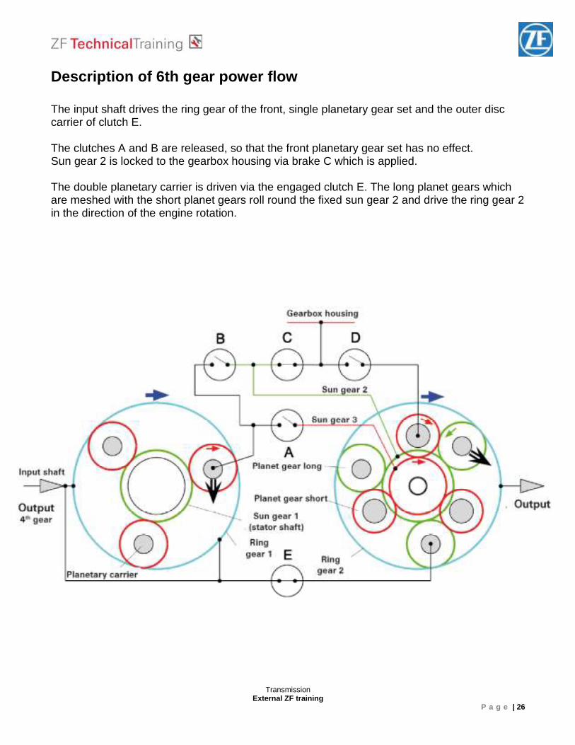
Description of 6th gear power flow The input shaft drives the ring gear of the front, single planetary gear set and the outer disc carrier of clutch E. The clutches A and B are released, so that the front planetary gear set has no effect. Sun gear 2 is locked to the gearbox housing via brake C which is applied. The double planetary carrier is driven via the engaged clutch E. The long planet gears which are meshed with the short planet gears roll round the fixed sun gear 2 and drive the ring gear 2 in the direction of the engine rotation.
Transmission External ZF training
P a g e | 27
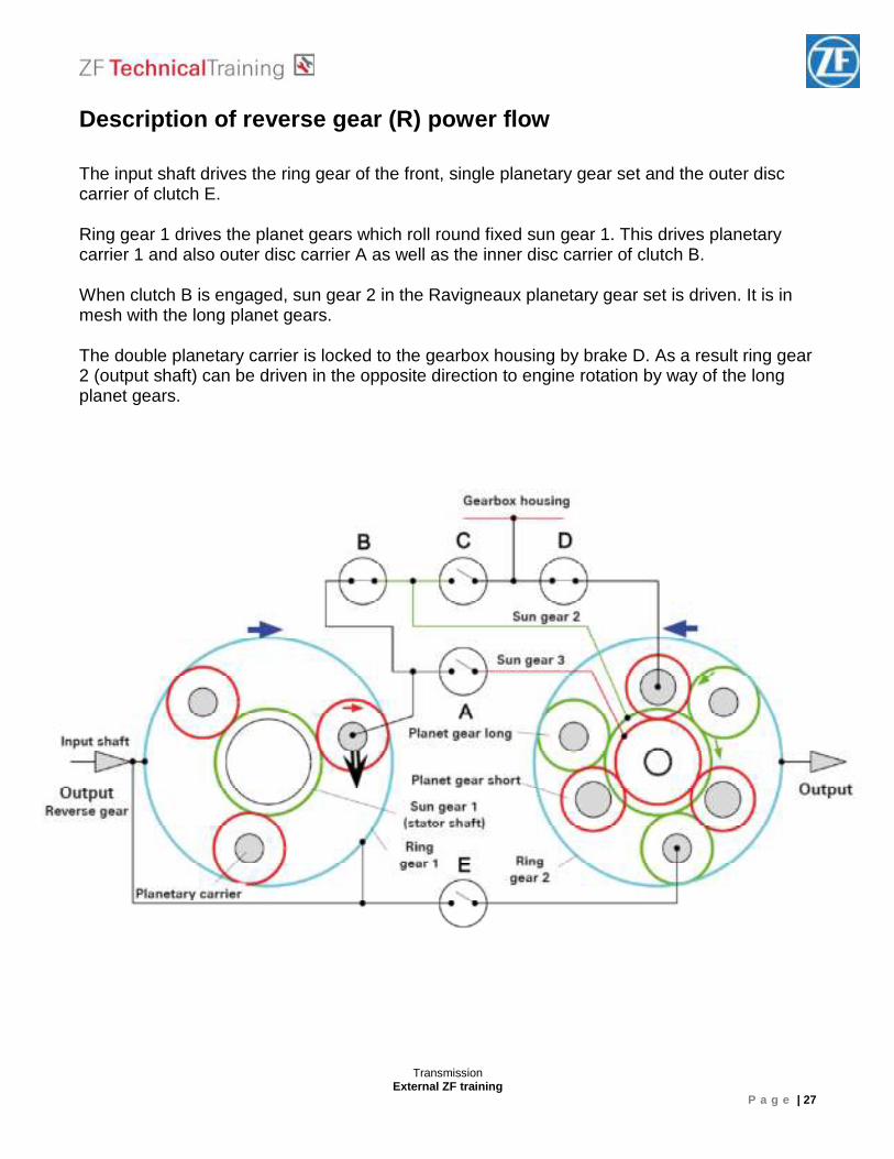
Description of reverse gear (R) power flow The input shaft drives the ring gear of the front, single planetary gear set and the outer disc carrier of clutch E. Ring gear 1 drives the planet gears which roll round fixed sun gear 1. This drives planetary carrier 1 and also outer disc carrier A as well as the inner disc carrier of clutch B. When clutch B is engaged, sun gear 2 in the Ravigneaux planetary gear set is driven. It is in mesh with the long planet gears. The double planetary carrier is locked to the gearbox housing by brake D. As a result ring gear 2 (output shaft) can be driven in the opposite direction to engine rotation by way of the long planet gears.
Transmission External ZF training
P a g e | 28
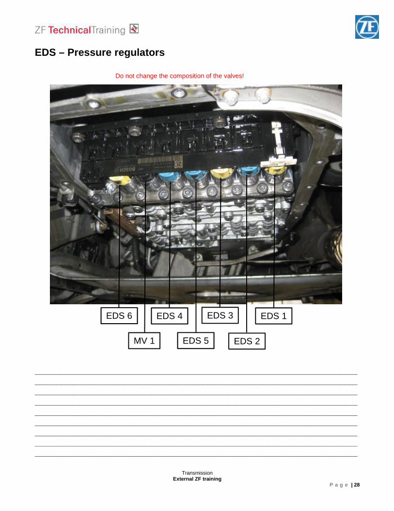
EDS – Pressure regulators Do not change the composition of the valves!
___________________________________________________________________________________________________________________________________________________________________________________________________________________________________________________________________________________________________________________________________________________________________________________________________________________________________________________________________________________________________________________________________________________________________________________________________________________________________________________________________________________________________
EDS 1 EDS 3
EDS 2
EDS 4
EDS 5
EDS 6
MV 1
Transmission External ZF training
P a g e | 29
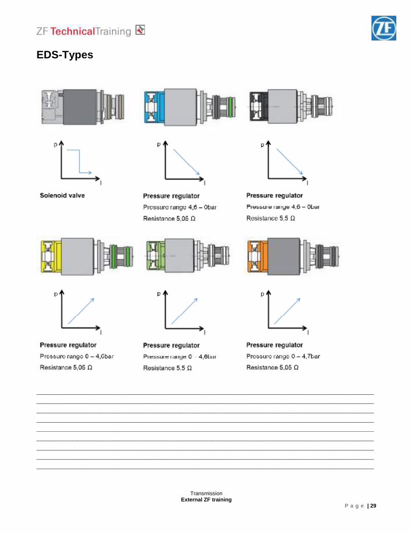
EDS-Types
___________________________________________________________________________________________________________________________________________________________________________________________________________________________________________________________________________________________________________________________________________________________________________________________________________________________________________________________________________________________________________________________________________________________________________________________________________________________________________________________________________________________________
Transmission External ZF training
P a g e | 30
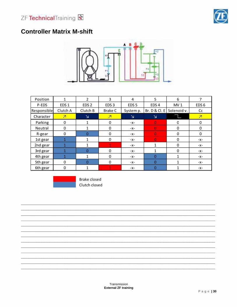
Controller Matrix M-shift
_______________________________________________________________________________________________________________________________________________________________________________________________________________________________________________________________________________________________________________________________________________________________________________________________________________________________________________________________________________________________________________________________________________________________________________________________________________________________________________________________________________________________________________________________________________________________________________________________________________________________________________________________________________________________________________________________________________________________________________________________________________
Position 1 2 3 4 5 6 7
P-EDS EDS 1 EDS 2 EDS 3 EDS 5 EDS 4 MV 1 EDS 6
Responsible Clutch A Clutch B Brake C System p. Br. D & Cl. E Solenoid v. Cc
Character ↗ ↘ ↗ ↘ ↘ ↗
Parking 0 1 0 -x- 0 0 0
Neutral 0 1 0 -x- 0 0 0
R-gear 0 0 0 -x- 0 0 0
1st gear 1 1 0 -x- 0 0 -x-
2nd gear 1 1 1 -x- 1 0 -x-
3rd gear 1 0 0 -x- 1 0 -x-
4th gear 1 1 0 -x- 0 1 -x-
5th gear 0 0 0 -x- 0 1 -x-
6th gear 0 1 1 -x- 0 1 -x-
Brake closed
Clutch closed
Transmission External ZF training
P a g e | 31
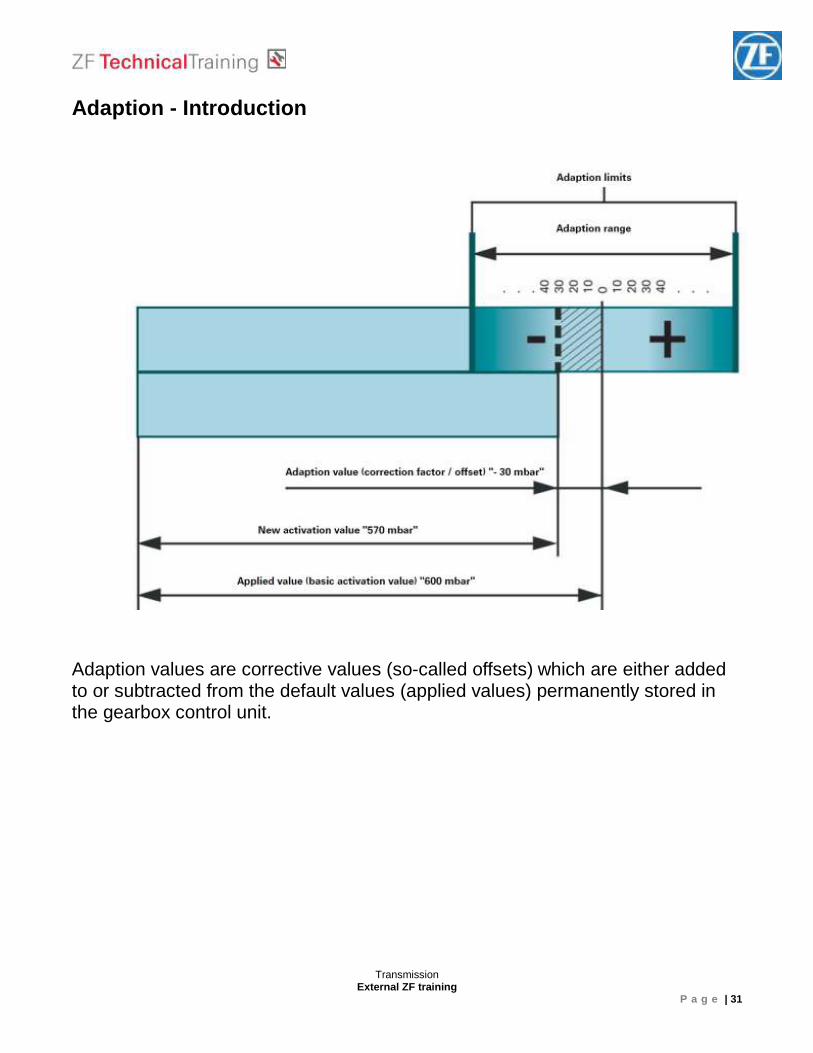
Adaption - Introduction Adaption values are corrective values (so-called offsets) which are either added to or subtracted from the default values (applied values) permanently stored in the gearbox control unit.
Transmission External ZF training
P a g e | 32
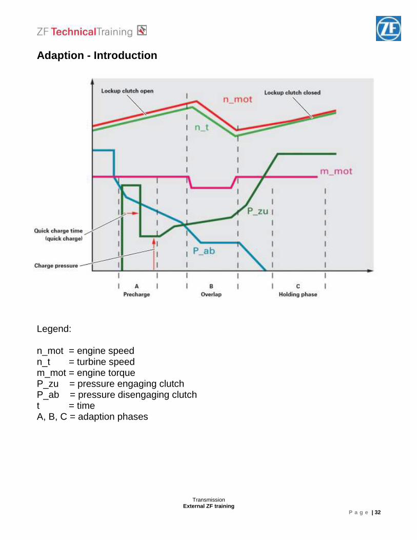
Adaption - Introduction Legend: n_mot = engine speed n_t = turbine speed m_mot = engine torque P_zu = pressure engaging clutch P_ab = pressure disengaging clutch t = time A, B, C = adaption phases
Transmission External ZF training
P a g e | 33
Adaption - Introduction Adaption of the precharge cycle... ... (charge pressure and quick charge time) adapts clutch play and clutch resistance until the clutch assembly makes contact, but still does not transmit an appreciable amount of torque. Adaption of the shift pressure... ... is based on an analysis of the change in gearbox input speed (engine speed gradient) during the gearshift. Example: During an excessively harsh gearshift (uncomfortable gearshift), the engine speed drops too quickly (steep engine speed gradient). The adaption program detects this condition from the engine speed gradients and reduces the clutch pressure by a defined amount (adaption value) during the next gearshift. This type of adaption is mainly carried out during the quick adaption cycle. Adaption of the holding pressure... ... is generally based on calculations made using the values determined during the charge pressure and shift pressure adaption.
Transmission External ZF training
P a g e | 34
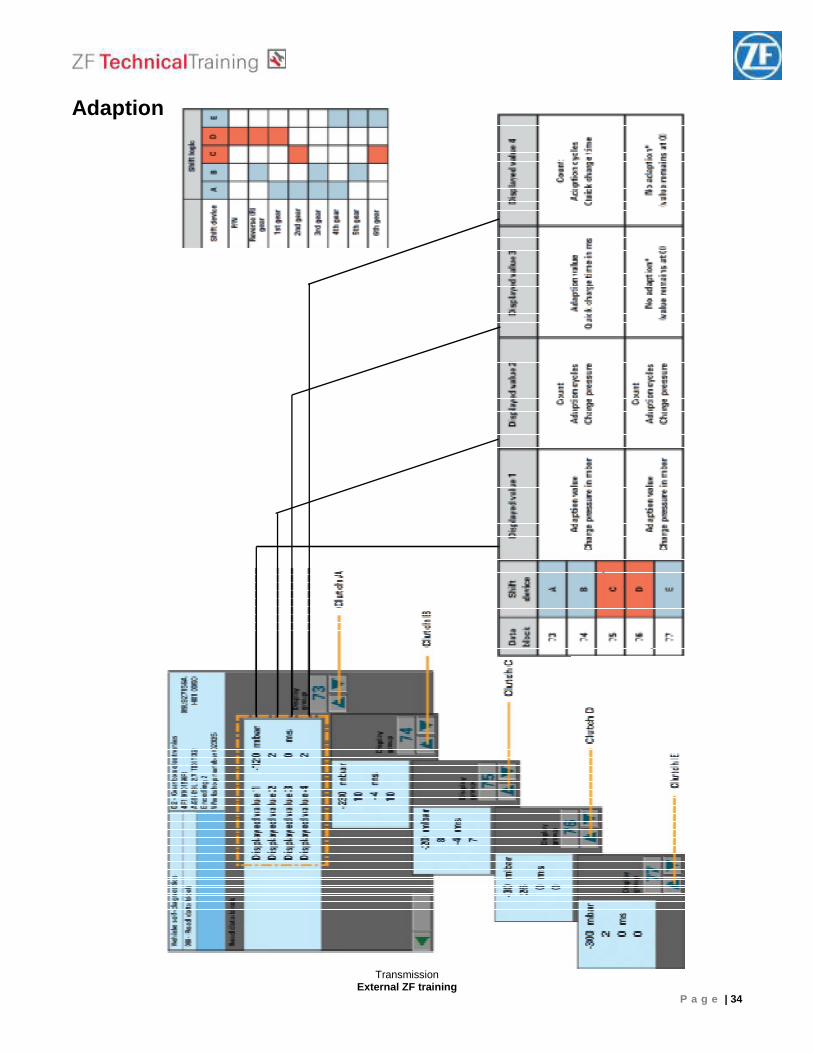
Adaption
Transmission External ZF training
P a g e | 35
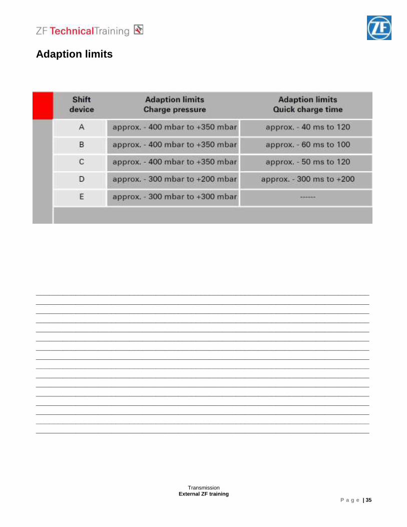
Adaption limits ____________________________________________________________________________________________________________________________________________________________________________________________________________________________________________________________________________________________________________ ____________________________________________________________________________________________________________________________________________________________________________________________________________________________________________________________________________________________________________ ____________________________________________________________________________________________________________________________________________________________________________________________________________________________________________________________________________________________________________ ____________________________________________________________________________________________________________________________________________________________________________________________________________________________________________________________________________________________________________
Transmission External ZF training
P a g e | 36
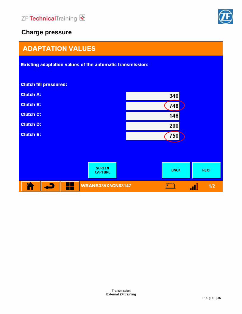
Charge pressure
Transmission External ZF training
P a g e | 37
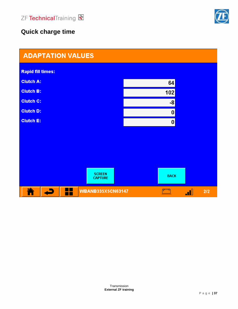
Quick charge time
Transmission External ZF training
P a g e | 38
Adaption drive (VW / Audi) Part A
Accelerate the vehicle from standing with very low throttle (15 – 25%) up to 4th gear and about 80 km/h. Freewheel the car down to about 40 km/h without using the brakes. Afterwards stop the car completely and stay in drive position for about 10 s. Repeat cycle 6 times.
Part B
Accelerate the vehicle up to about 70 km/h und select manually 5th gear. Use
your diagnostic tool (VW/Audi block 9) to drive with 100 Nm for about 3 – 4 km.
Accelerate the vehicle up to about 85 km/h und select manually 6th gear. Use
your diagnostic tool (VW/Audi block 9) to drive with 100 Nm for about 3 – 4 km.
Part C
Accelerate 5 times with low throttle up to about 100 km/h and freewheel the car down to about 40 km/h without using the brakes.
Transmission External ZF training
P a g e | 39
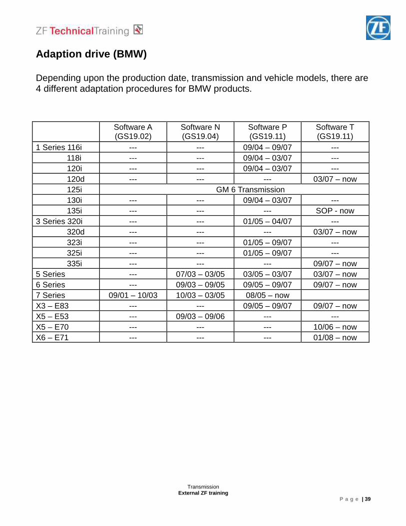
Adaption drive (BMW) Depending upon the production date, transmission and vehicle models, there are 4 different adaptation procedures for BMW products. Software A
(GS19.02) Software N (GS19.04)
Software P (GS19.11)
Software T (GS19.11)
1 Series 116i --- --- 09/04 – 09/07 --- 118i --- --- 09/04 – 03/07 --- 120i --- --- 09/04 – 03/07 --- 120d --- --- --- 03/07 – now 125i GM 6 Transmission 130i --- --- 09/04 – 03/07 --- 135i --- --- --- SOP - now 3 Series 320i --- --- 01/05 – 04/07 --- 320d --- --- --- 03/07 – now 323i --- --- 01/05 – 09/07 --- 325i --- --- 01/05 – 09/07 --- 335i --- --- --- 09/07 – now 5 Series --- 07/03 – 03/05 03/05 – 03/07 03/07 – now 6 Series --- 09/03 – 09/05 09/05 – 09/07 09/07 – now 7 Series 09/01 – 10/03 10/03 – 03/05 08/05 – now X3 – E83 --- --- 09/05 – 09/07 09/07 – now X5 – E53 --- 09/03 – 09/06 --- --- X5 – E70 --- --- --- 10/06 – now X6 – E71 --- --- --- 01/08 – now
Transmission External ZF training
P a g e | 40
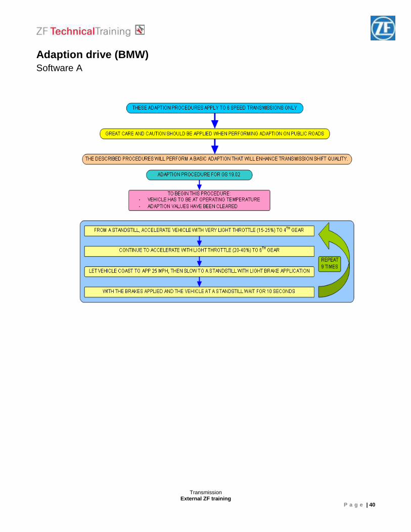
Adaption drive (BMW) Software A
Transmission External ZF training
P a g e | 41
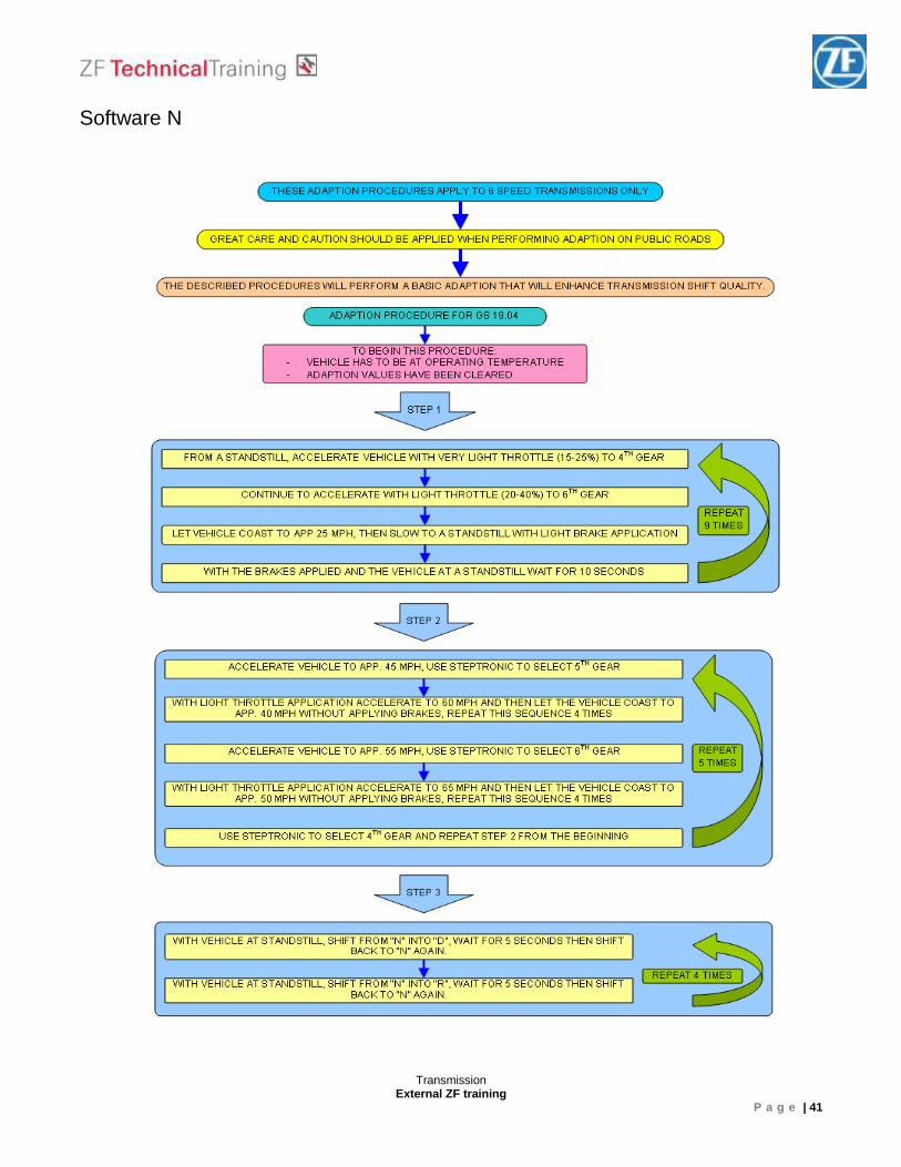
Software N
Transmission External ZF training
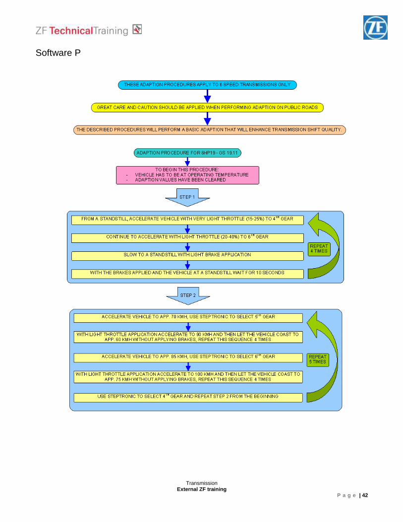
P a g e | 42
Software P
Transmission External ZF training
P a g e | 43
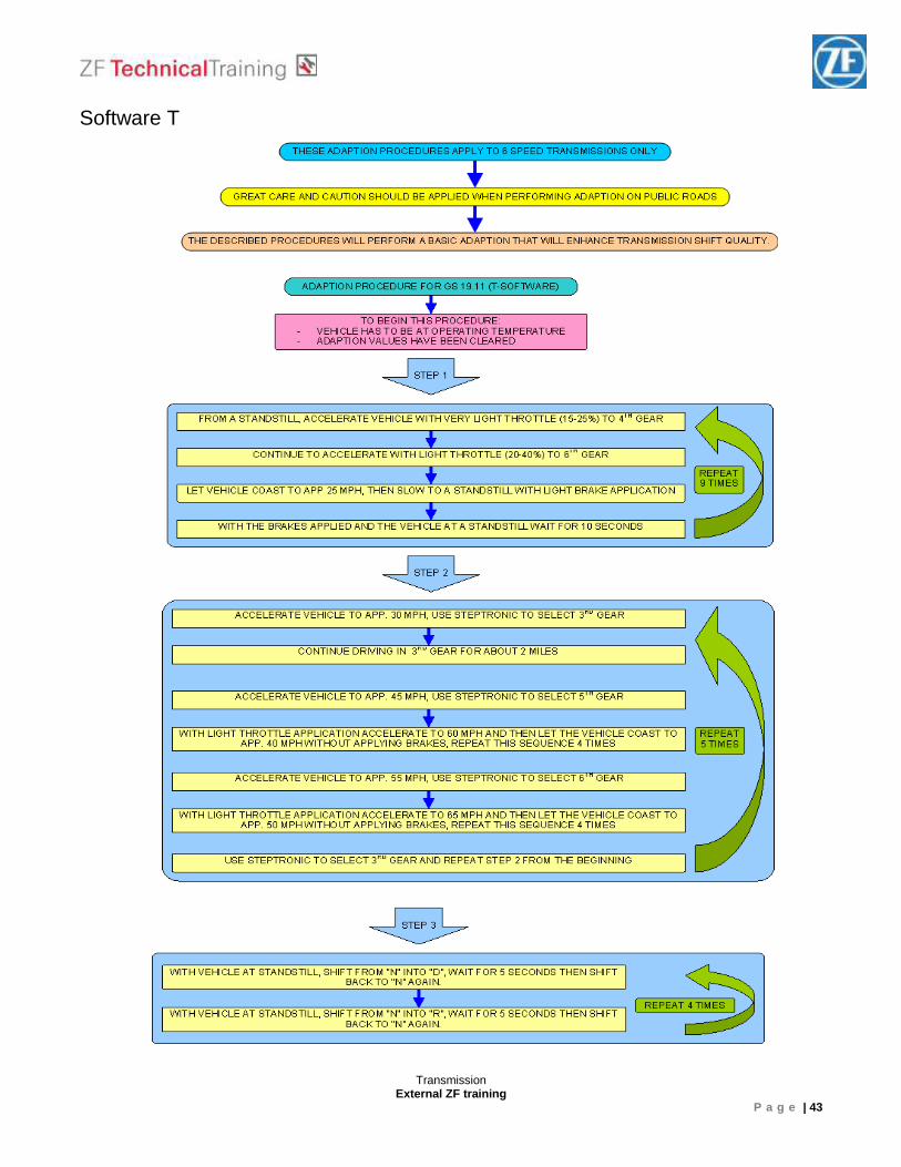
Software T
Transmission External ZF training
P a g e | 44
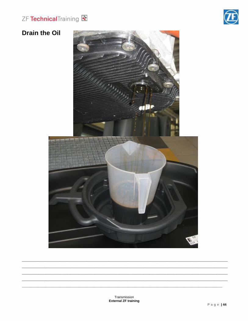
Drain the Oil
__________________________________________________________________________________________________________________________________________________________________________________________________________________________________________________________________________________________________________________________________________________________________________________________
Transmission External ZF training
P a g e | 45
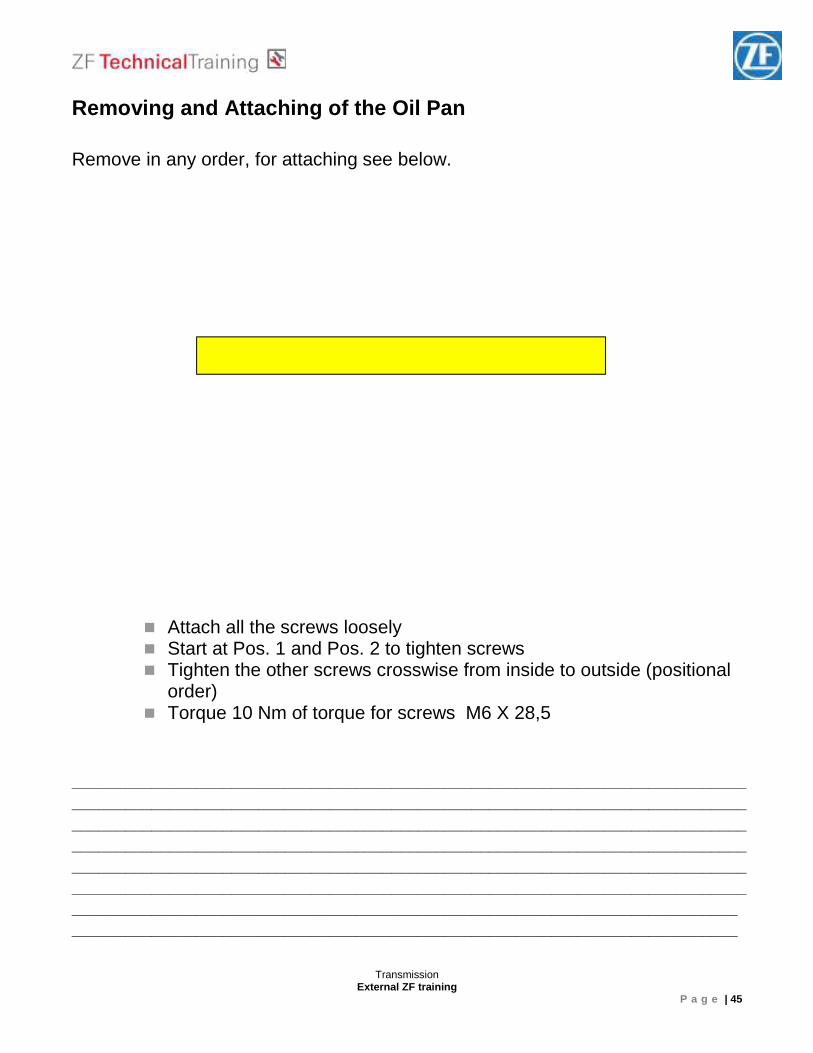
Removing and Attaching of the Oil Pan Remove in any order, for attaching see below.
� Attach all the screws loosely � Start at Pos. 1 and Pos. 2 to tighten screws � Tighten the other screws crosswise from inside to outside (positional
order) � Torque 10 Nm of torque for screws M6 X 28,5
___________________________________________________________________________________________________________________________________________________________________________________________________________________________________________________________________________________________________________________________________________________________________________________________________________________________________________________________________________________________________________________________________________________ ___________________________________________________________________________
Start here to tighten the screws
Transmission External ZF training
P a g e | 46
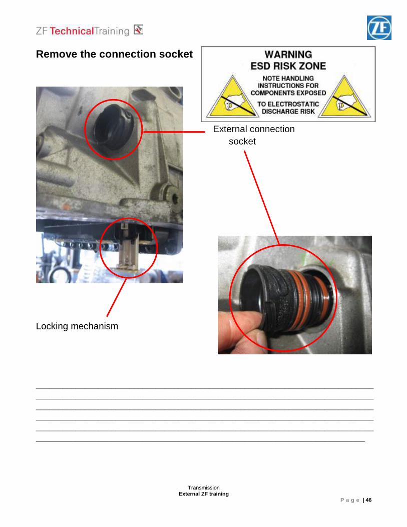
Remove the connection socket
External connection socket
Locking mechanism
______________________________________________________________________________________________________________________________________________________________________________________________________________________________________________________________________________________________________________________________________________________________________________________________________________________________________________________________________
Transmission External ZF training
P a g e | 47
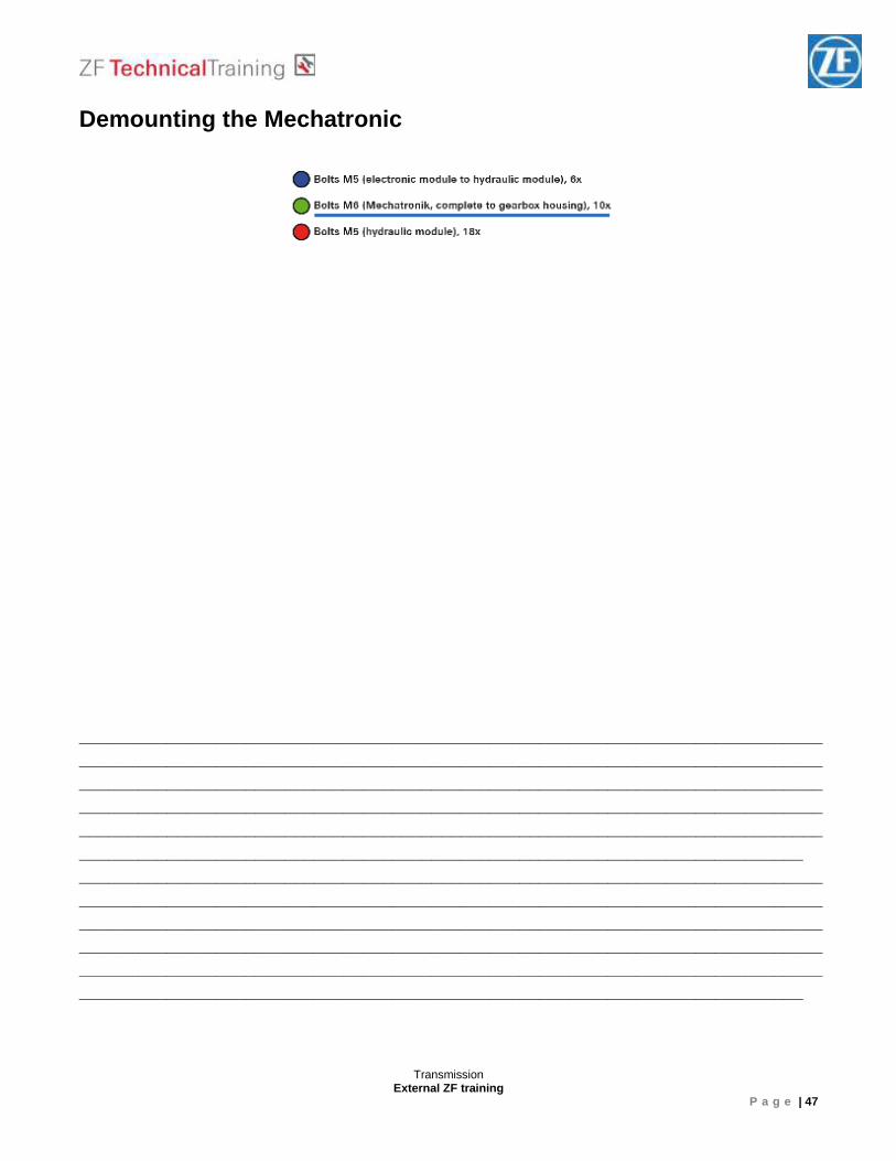
Demounting the Mechatronic ______________________________________________________________________________________________________________________________________________________________________________________________________________________________________________________________________________________________________________________________________________________________________________________________________________________________________________________________________ ______________________________________________________________________________________________________________________________________________________________________________________________________________________________________________________________________________________________________________________________________________________________________________________________________________________________________________________________________
Transmission External ZF training
P a g e | 48
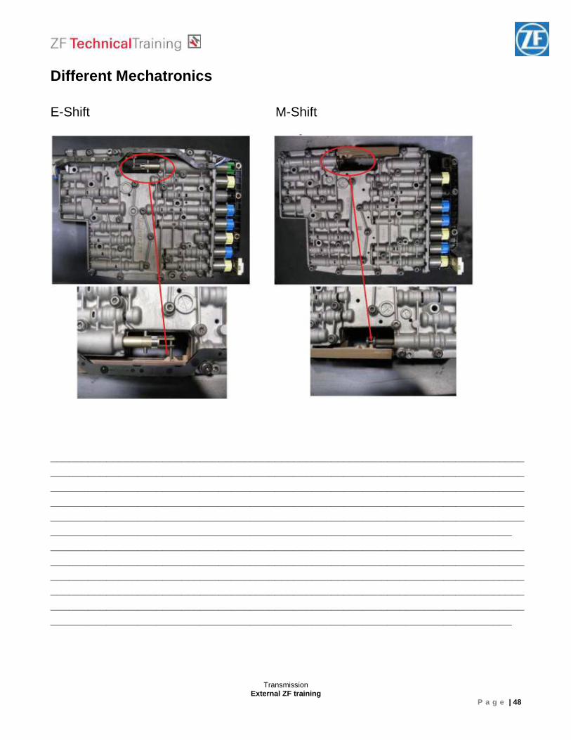
Different Mechatronics E-Shift M-Shift ______________________________________________________________________________________________________________________________________________________________________________________________________________________________________________________________________________________________________________________________________________________________________________________________________________________________________________________________________ ______________________________________________________________________________________________________________________________________________________________________________________________________________________________________________________________________________________________________________________________________________________________________________________________________________________________________________________________________
Transmission External ZF training
P a g e | 49
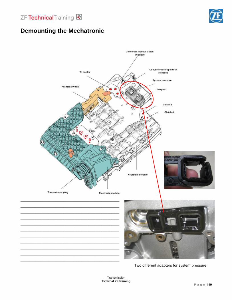
Demounting the Mechatronic
_____________________________________________________________________________________________________________________________________________________________________________________________________________________________________________________________________________________________________________________________________________________________________________________________________________________________________________ Two different adapters for system pressure
Transmission External ZF training
P a g e | 50
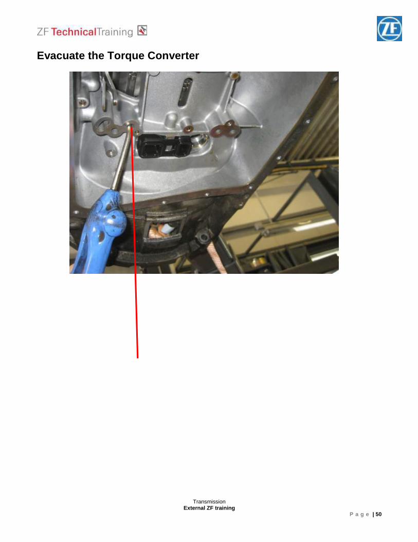
Evacuate the Torque Converter

Transmission External ZF training
P a g e | 51
Check clutches and brakes
Transmission External ZF training
P a g e | 52
Dismounted Mechatronic (E shift)
Transmission External ZF training
P a g e | 53
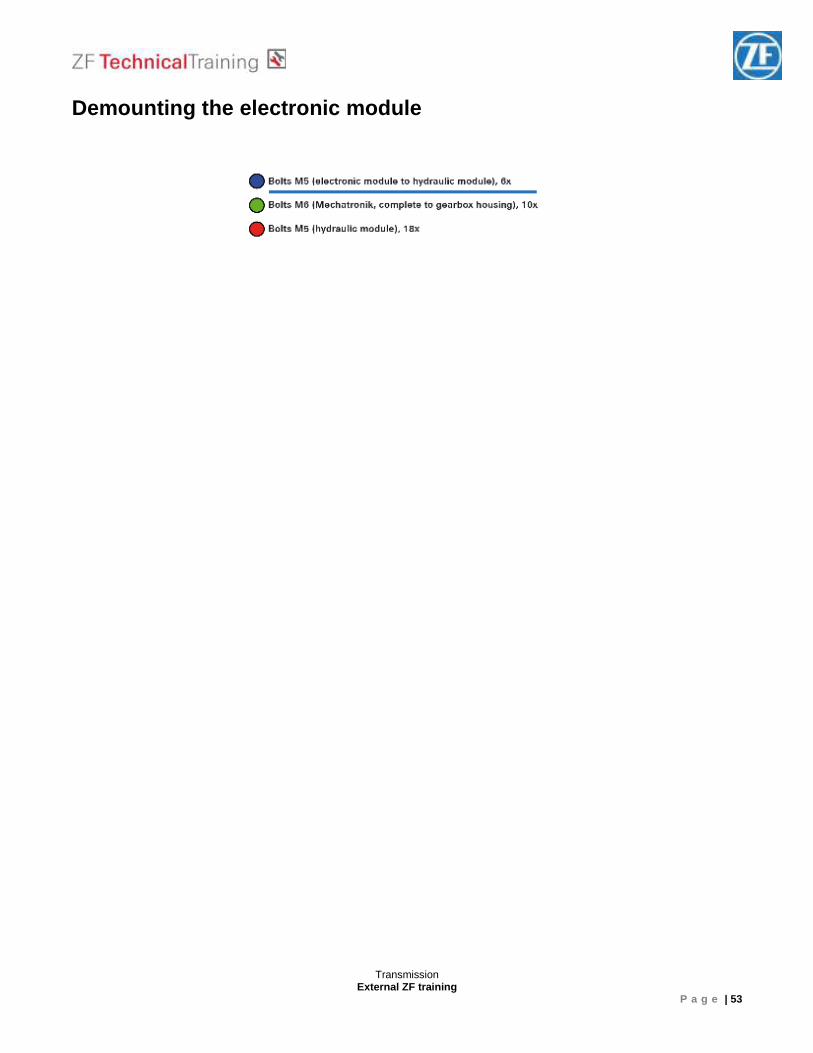
Demounting the electronic module
Transmission External ZF training
P a g e | 54
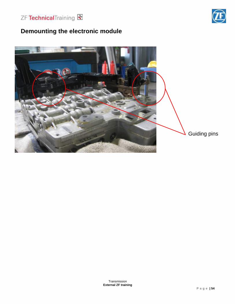
Demounting the electronic module
Guiding pins
Transmission External ZF training
P a g e | 55
Opening the Mechatronic
Transmission External ZF training
P a g e | 56
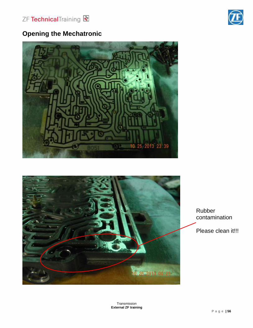
Opening the Mechatronic
Rubber contamination Please clean it!!!
Transmission External ZF training
P a g e | 57
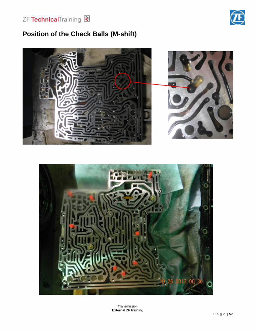
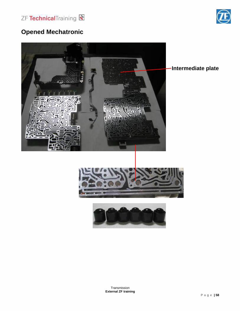
Position of the Check Balls (M-shift)
Transmission External ZF training
P a g e | 58
Opened Mechatronic
Intermediate plate

Transmission External ZF training
P a g e | 59
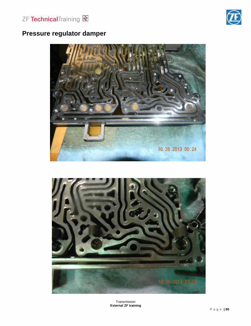
Pressure regulator damper
Transmission External ZF training
P a g e | 60
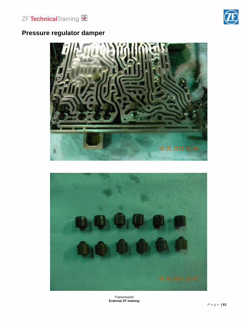
Pressure regulator damper
Transmission External ZF training
P a g e | 61
Pressure regulator damper
Transmission External ZF training
P a g e | 62
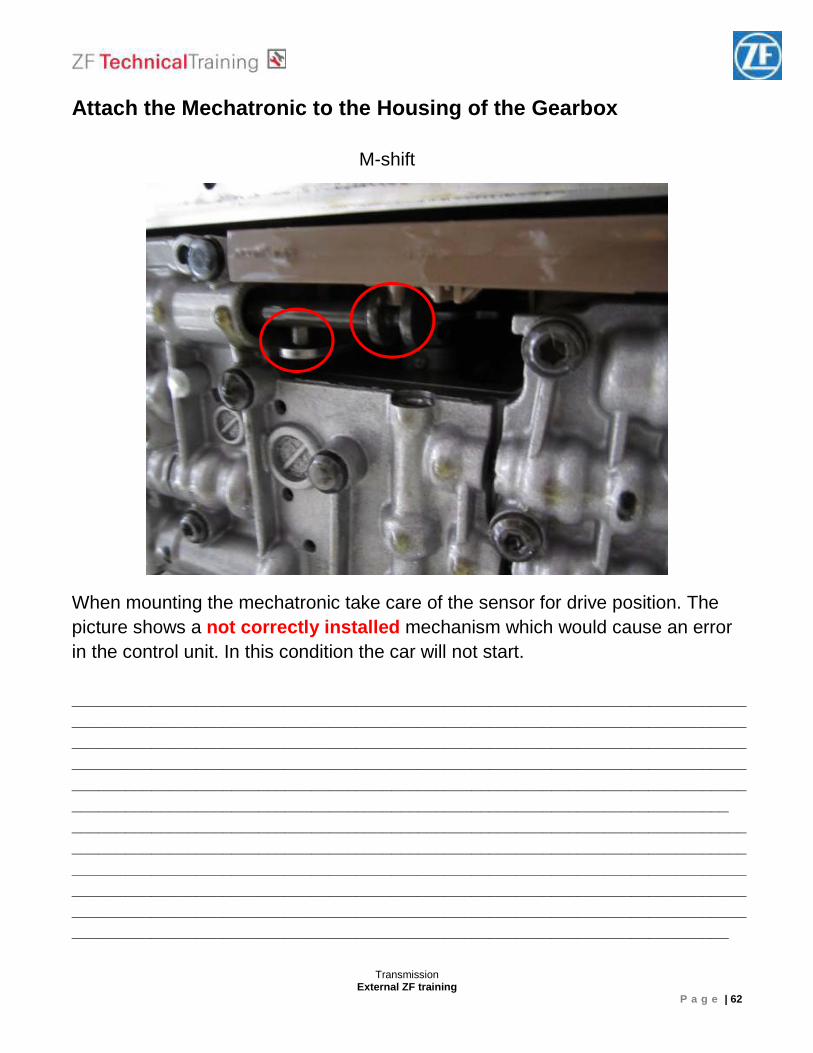
Attach the Mechatronic to the Housing of the Gearbo x M-shift When mounting the mechatronic take care of the sensor for drive position. The picture shows a not correctly installed mechanism which would cause an error in the control unit. In this condition the car will not start. ______________________________________________________________________________________________________________________________________________________________________________________________________________________________________________________________________________________________________________________________________________________________________________________________________________________________________________________________________ ______________________________________________________________________________________________________________________________________________________________________________________________________________________________________________________________________________________________________________________________________________________________________________________________________________________________________________________________________
Transmission External ZF training
P a g e | 63
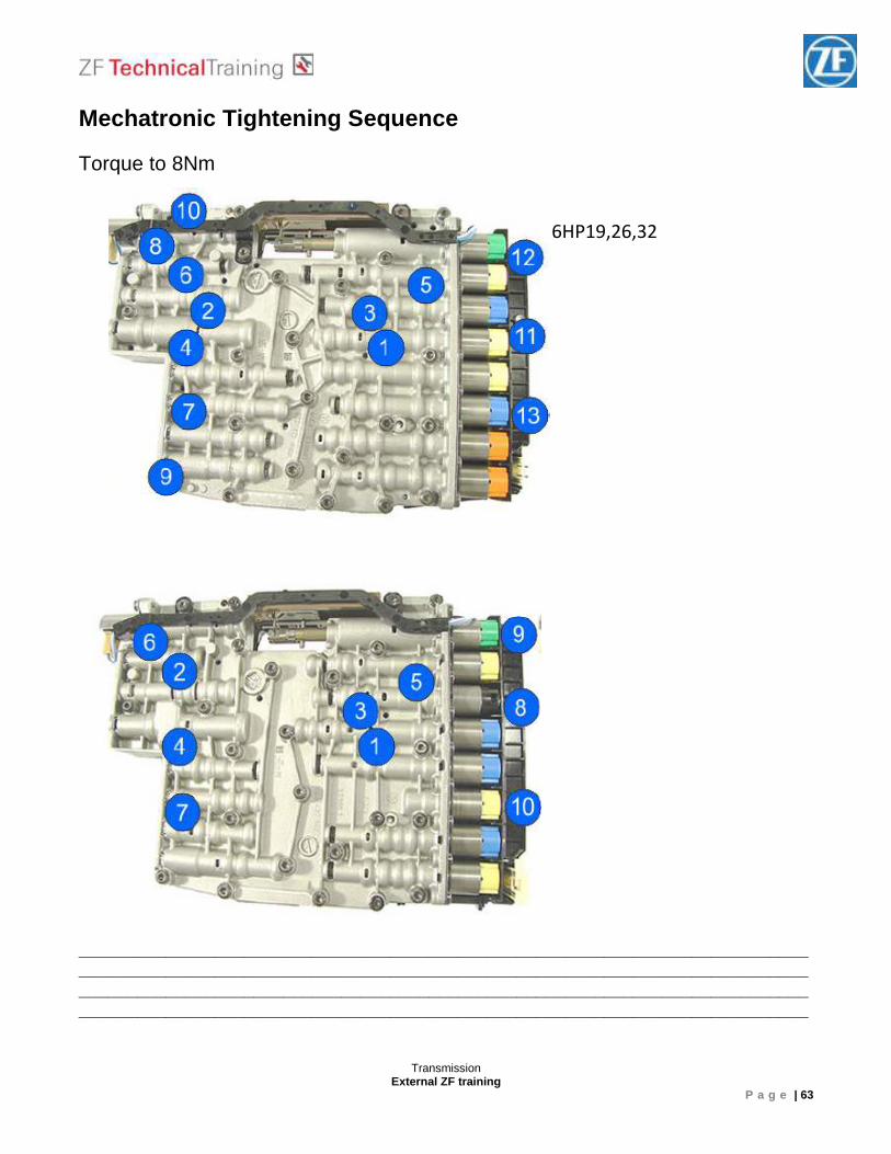
Mechatronic Tightening Sequence Torque to 8Nm ____________________________________________________________________________________________________________________________________________________________________________________________________________________________________________________________________________________________________________
6HP19,26,32
Transmission External ZF training
P a g e | 64
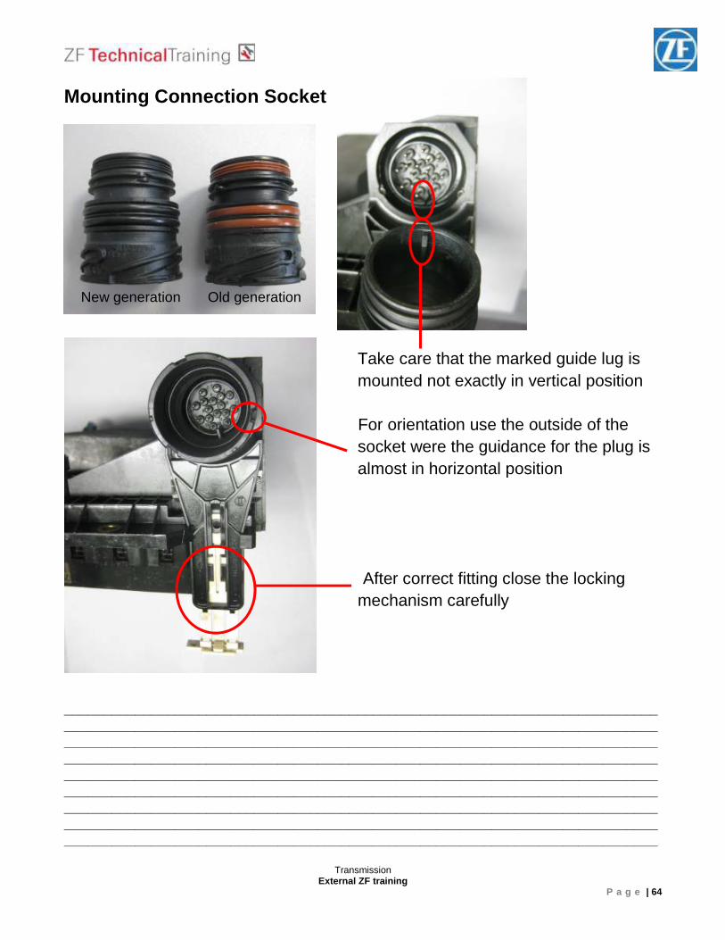
Mounting Connection Socket
Take care that the marked guide lug is mounted not exactly in vertical position
For orientation use the outside of the socket were the guidance for the plug is almost in horizontal position
After correct fitting close the locking mechanism carefully
___________________________________________________________________________ ____________________________________________________________________________________________________________________________________________________________________________________________________________________________________________________________________________________________________________ ___________________________________________________________________________ _________________________________________________________________________________________________________________________________________________________________________________________________________________________________
New generation Old generation
Transmission External ZF training
P a g e | 65
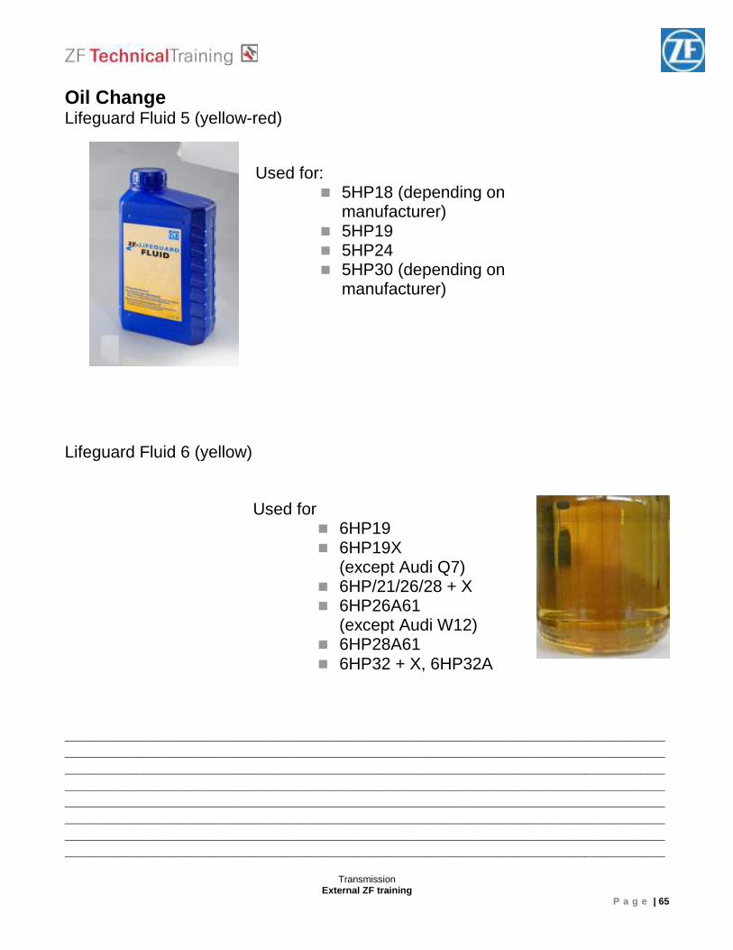
Oil Change Lifeguard Fluid 5 (yellow-red) Lifeguard Fluid 6 (yellow) ____________________________________________________________________________________________________________________________________________________________________________________________________________________________________________________________________________________________________________ ____________________________________________________________________________________________________________________________________________________________________________________________________________________________________________________________________________________________________________
Used for: � 5HP18 (depending on
manufacturer) � 5HP19 � 5HP24 � 5HP30 (depending on
manufacturer)
Used for � 6HP19 � 6HP19X
(except Audi Q7) � 6HP/21/26/28 + X � 6HP26A61
(except Audi W12) � 6HP28A61 � 6HP32 + X, 6HP32A
Transmission External ZF training
P a g e | 66
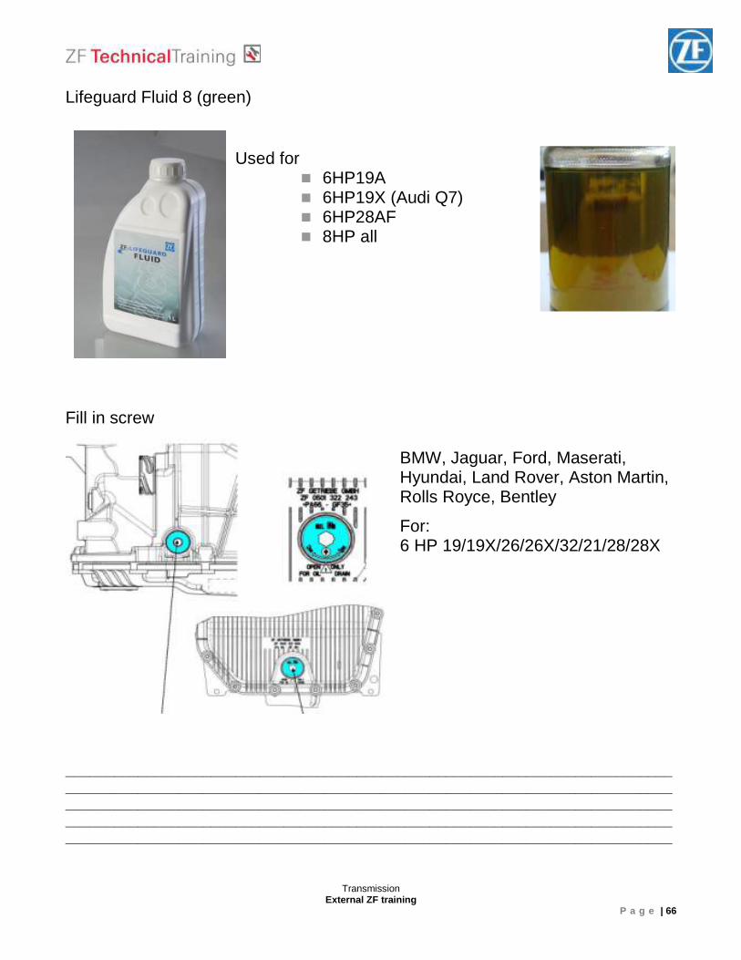
Lifeguard Fluid 8 (green) Fill in screw ___________________________________________________________________________ ____________________________________________________________________________________________________________________________________________________________________________________________________________________________________________________________________________________________________________
Used for � 6HP19A � 6HP19X (Audi Q7) � 6HP28AF � 8HP all
BMW, Jaguar, Ford, Maserati, Hyundai, Land Rover, Aston Martin, Rolls Royce, Bentley
For: 6 HP 19/19X/26/26X/32/21/28/28X
Transmission External ZF training
P a g e | 67
Fill in screw (Audi) Oil level control (Audi)
____________________________________________________________________________________________________________________________________________________________________________________________________________________________________________________________________________________________________________ ____________________________________________________________________________________________________________________________________________________________________________________________________________________________________________________________________________________________________________
� Engine rpm 750 1/min � Gearbox temperature
between 35 and 40 °
� Gearbox temperature 35°
� Start engine � Take screw B out � Screw worn � No fluid coming
fill up until ATF runs down
Transmission External ZF training
P a g e | 68
Bolted driveshaft
____________________________________________________________________________________________________________________________________________________________________________________________________________________________________________________________________________________________________________ ____________________________________________________________________________________________________________________________________________________________________________________________________________________________________________________________________________________________________________
Transmission External ZF training
P a g e | 69
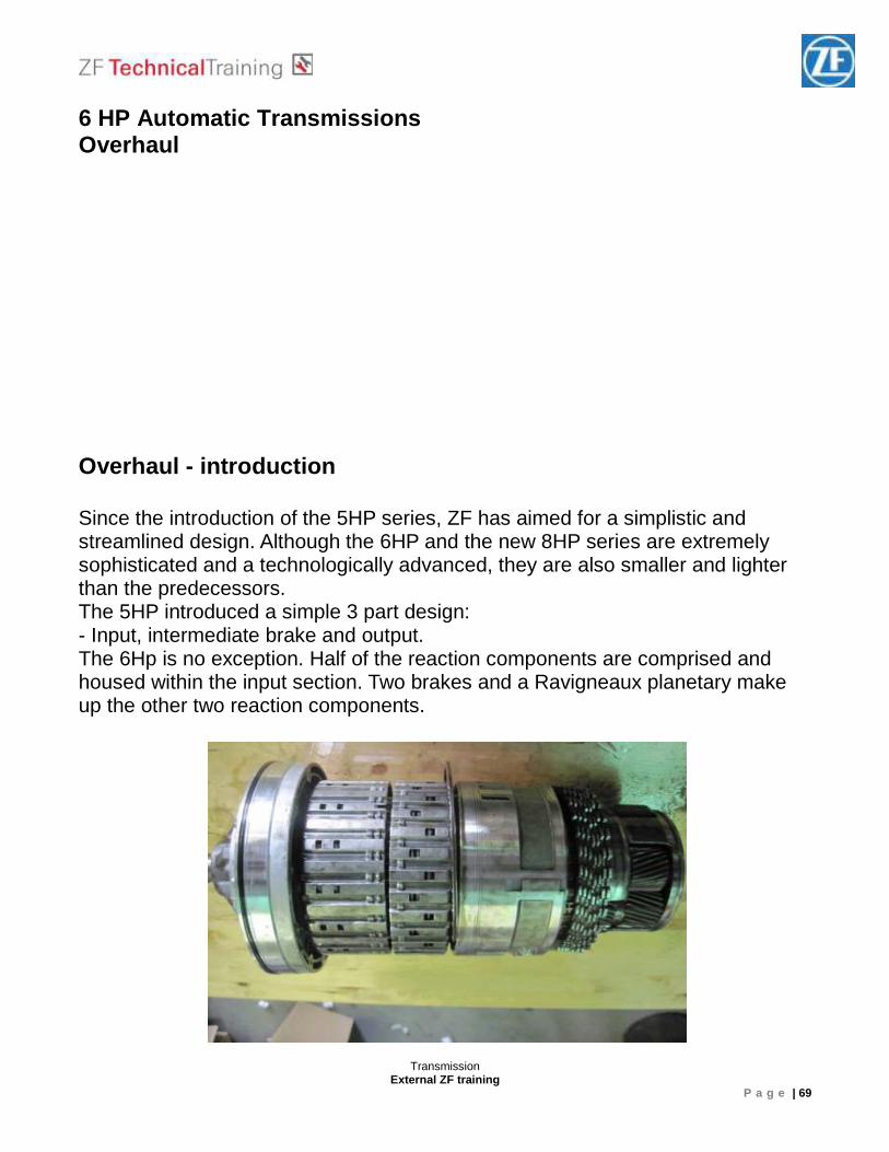
6 HP Automatic Transmissions Overhaul Overhaul - introduction Since the introduction of the 5HP series, ZF has aimed for a simplistic and streamlined design. Although the 6HP and the new 8HP series are extremely sophisticated and a technologically advanced, they are also smaller and lighter than the predecessors. The 5HP introduced a simple 3 part design: - Input, intermediate brake and output. The 6Hp is no exception. Half of the reaction components are comprised and housed within the input section. Two brakes and a Ravigneaux planetary make up the other two reaction components.
Transmission External ZF training
P a g e | 70
Input section – Oil pump Front cover housing contains:
• Oil pump • Torque converter stator support • Single planetary’ s Sun gear support • Oil passages for TCC apply and release
Transmission External ZF training
P a g e | 71
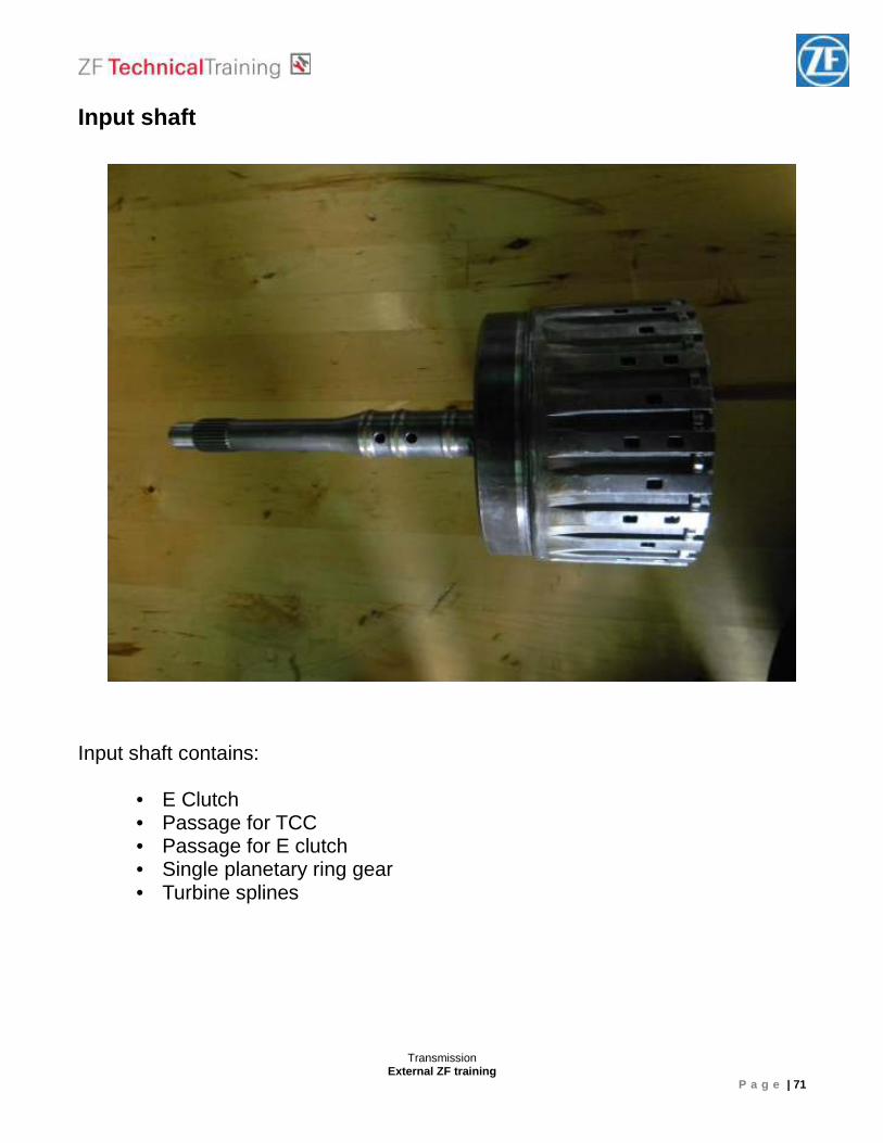
Input shaft Input shaft contains:
• E Clutch • Passage for TCC • Passage for E clutch • Single planetary ring gear • Turbine splines
Transmission External ZF training
P a g e | 72
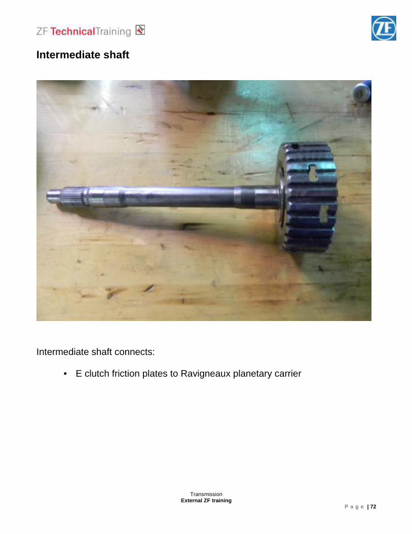
Intermediate shaft Intermediate shaft connects:
• E clutch friction plates to Ravigneaux planetary carrier
Transmission External ZF training
P a g e | 73
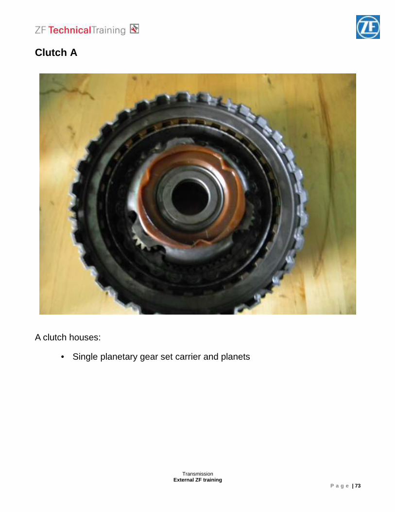
Clutch A A clutch houses:
• Single planetary gear set carrier and planets
Transmission External ZF training
P a g e | 74
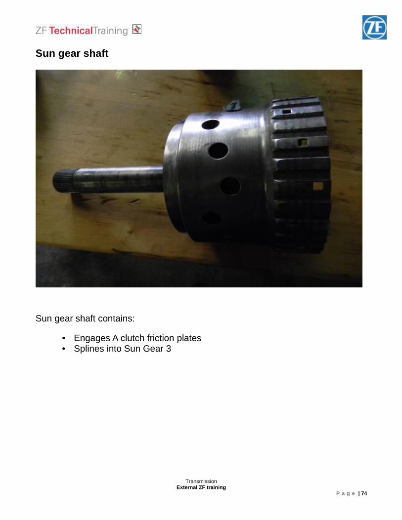
Sun gear shaft Sun gear shaft contains:
• Engages A clutch friction plates • Splines into Sun Gear 3
Transmission External ZF training
P a g e | 75
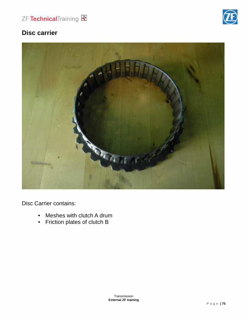
Disc carrier Disc Carrier contains:
• Meshes with clutch A drum • Friction plates of clutch B
Transmission External ZF training
P a g e | 76
Clutch B
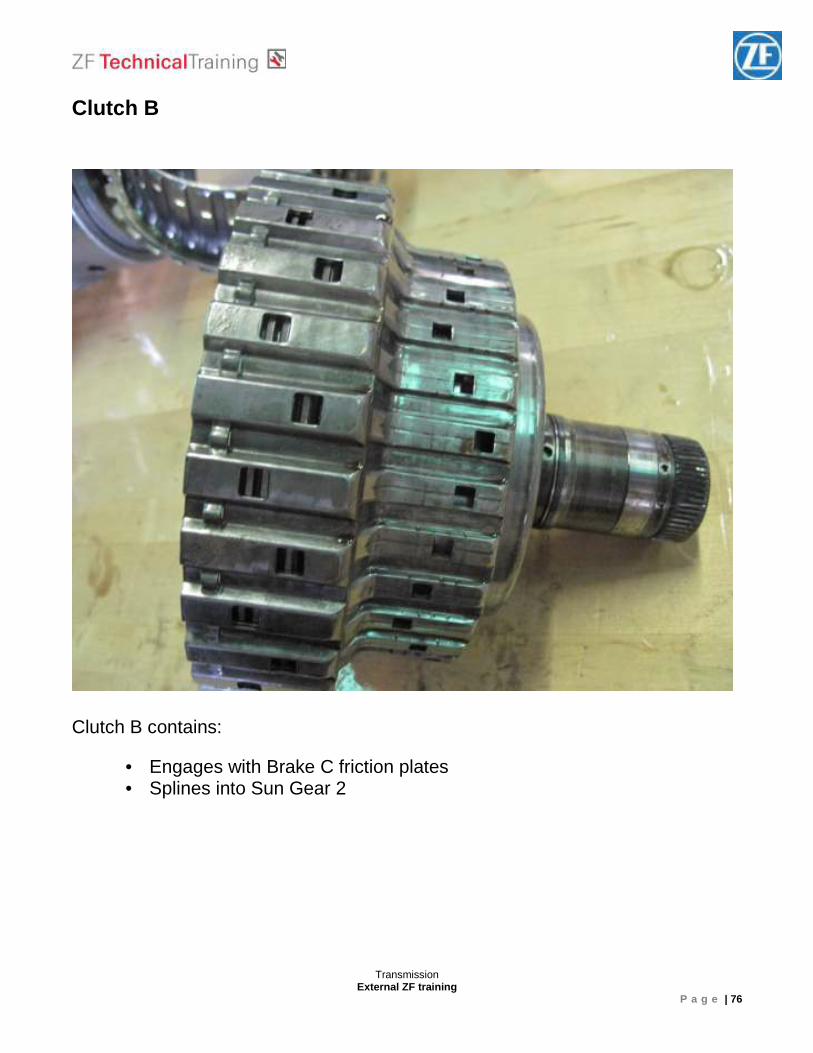
Clutch B contains:
• Engages with Brake C friction plates • Splines into Sun Gear 2
Transmission External ZF training
P a g e | 77
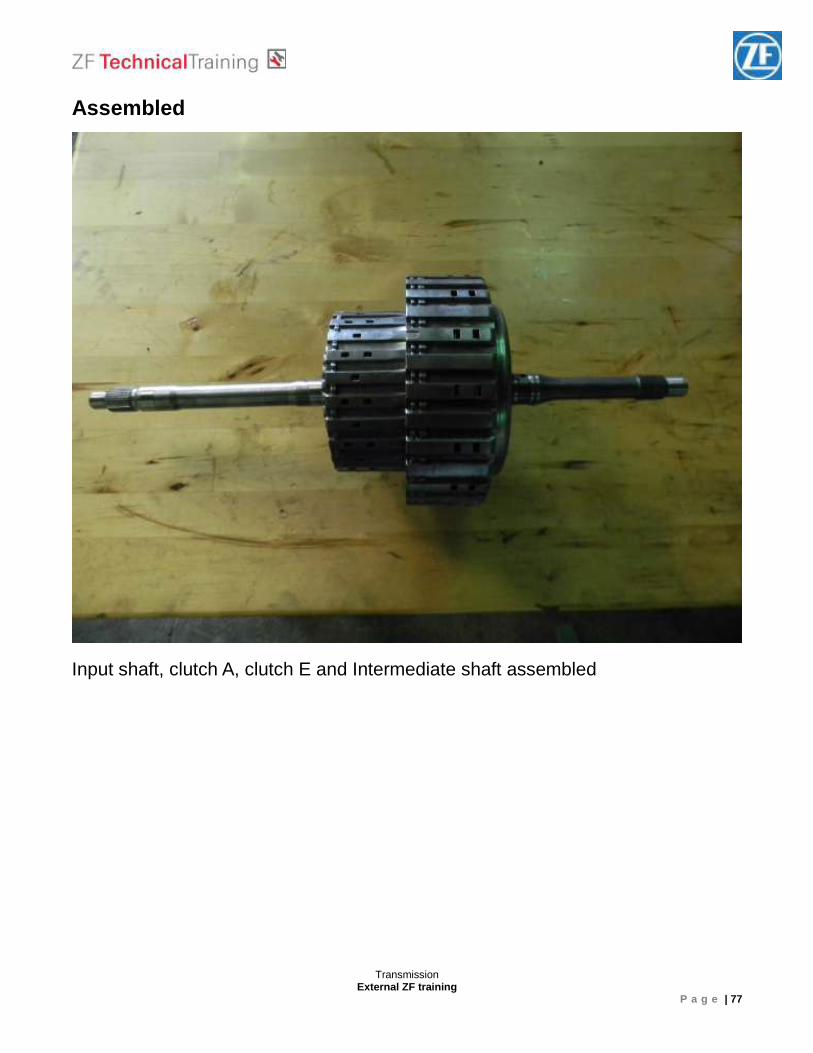
Assembled Input shaft, clutch A, clutch E and Intermediate shaft assembled
Transmission External ZF training
P a g e | 78
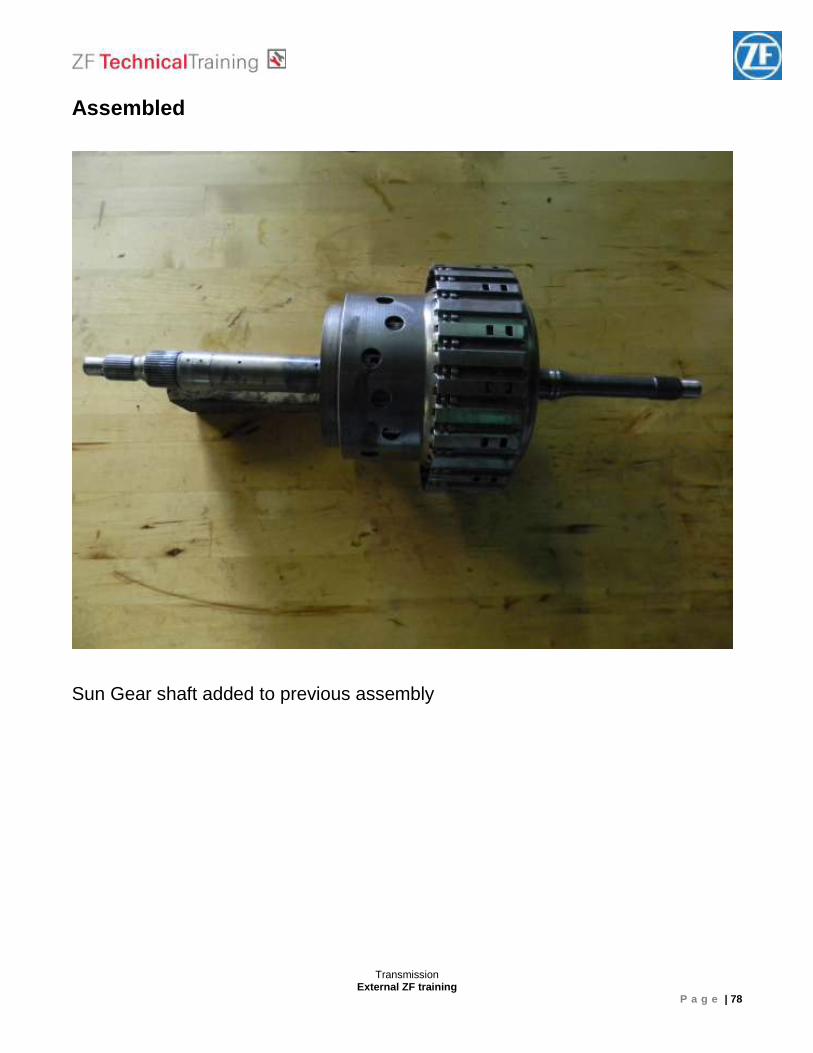
Assembled Sun Gear shaft added to previous assembly
Transmission External ZF training
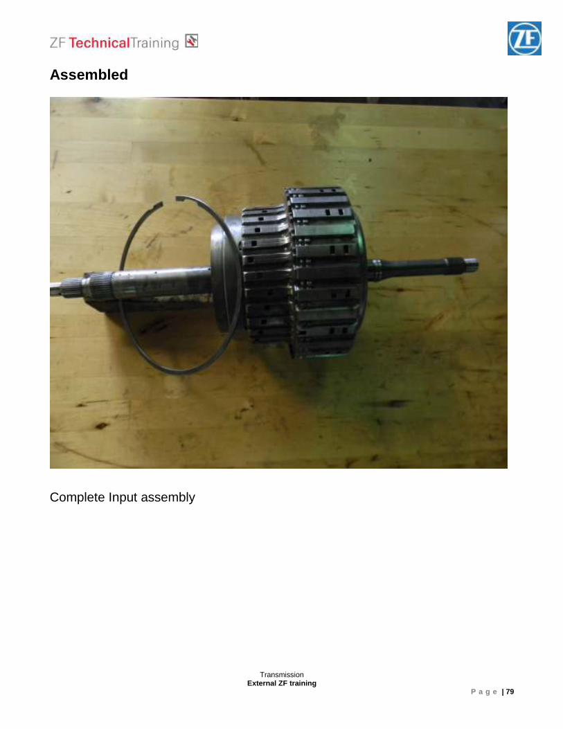
P a g e | 79
Assembled Complete Input assembly
Transmission External ZF training
P a g e | 80
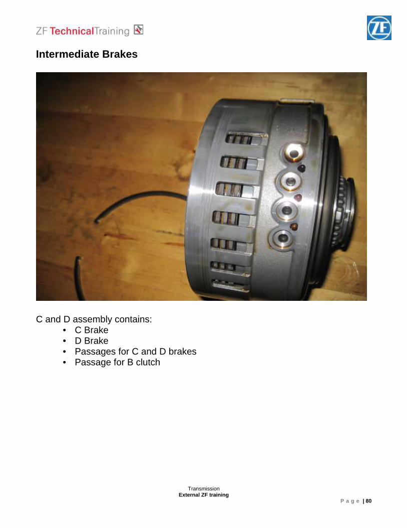
Intermediate Brakes
C and D assembly contains:
• C Brake • D Brake • Passages for C and D brakes • Passage for B clutch
Transmission External ZF training
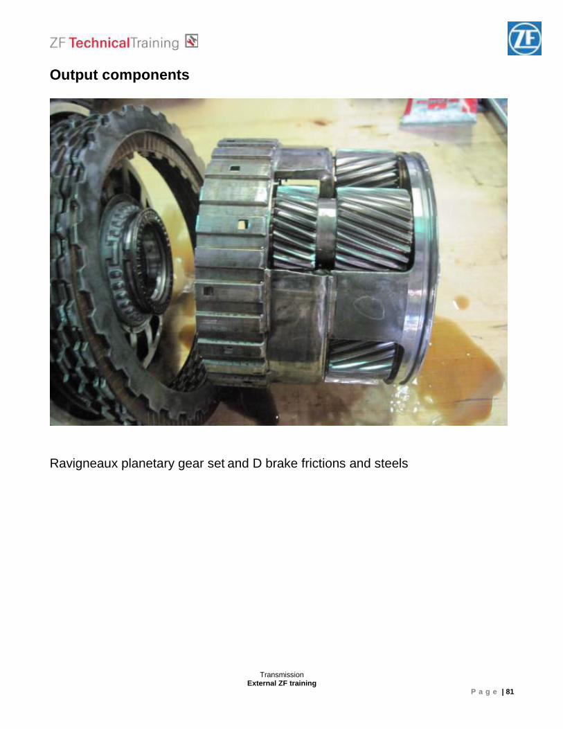
P a g e | 81
Output components Ravigneaux planetary gear set and D brake frictions and steels
Transmission External ZF training
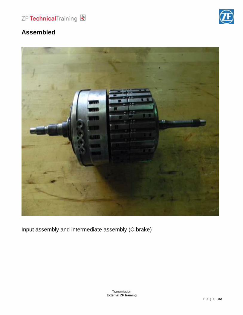
P a g e | 82
Assembled Input assembly and intermediate assembly (C brake)
Transmission External ZF training
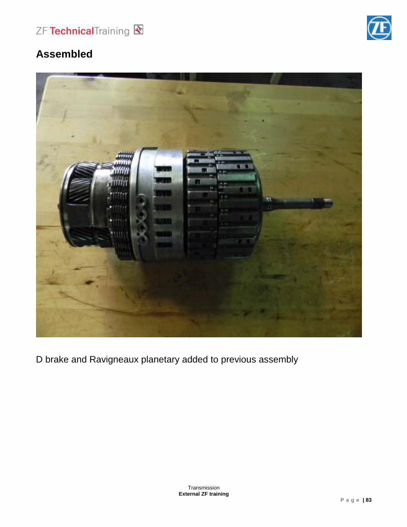
P a g e | 83
Assembled D brake and Ravigneaux planetary added to previous assembly
Transmission External ZF training
P a g e | 84
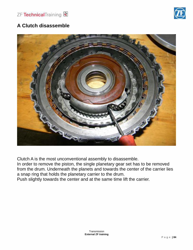
A Clutch disassemble Clutch A is the most unconventional assembly to disassemble. In order to remove the piston, the single planetary gear set has to be removed from the drum. Underneath the planets and towards the center of the carrier lies a snap ring that holds the planetary carrier to the drum. Push slightly towards the center and at the same time lift the carrier.
Transmission External ZF training
P a g e | 85
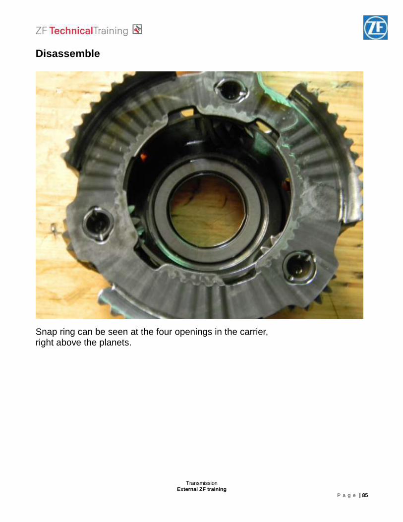
Disassemble Snap ring can be seen at the four openings in the carrier, right above the planets.
Transmission External ZF training
P a g e | 86
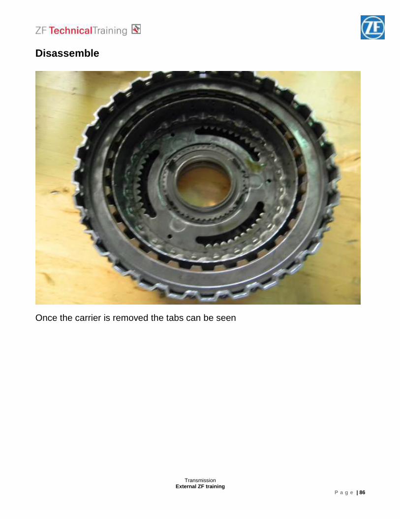
Disassemble Once the carrier is removed the tabs can be seen
Transmission External ZF training
P a g e | 87
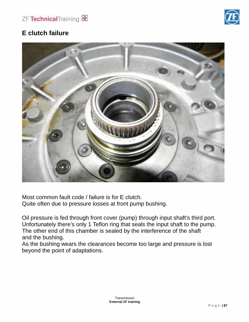
E clutch failure Most common fault code / failure is for E clutch. Quite often due to pressure losses at front pump bushing. Oil pressure is fed through front cover (pump) through input shaft’s third port. Unfortunately there’s only 1 Teflon ring that seals the input shaft to the pump. The other end of this chamber is sealed by the interference of the shaft and the bushing. As the bushing wears the clearances become too large and pressure is lost beyond the point of adaptations.
Transmission External ZF training
P a g e | 88
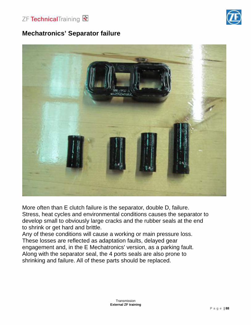
Mechatronics’ Separator failure
More often than E clutch failure is the separator, double D, failure. Stress, heat cycles and environmental conditions causes the separator to develop small to obviously large cracks and the rubber seals at the end to shrink or get hard and brittle. Any of these conditions will cause a working or main pressure loss. These losses are reflected as adaptation faults, delayed gear engagement and, in the E Mechatronics' version, as a parking fault. Along with the separator seal, the 4 ports seals are also prone to shrinking and failure. All of these parts should be replaced.
Transmission External ZF training
P a g e | 89
8 HP Automatic Transmissions Modular construction system
Transmission External ZF training
P a g e | 90
Torque converter Sealing gearbox input shaft
Transmission External ZF training
P a g e | 91
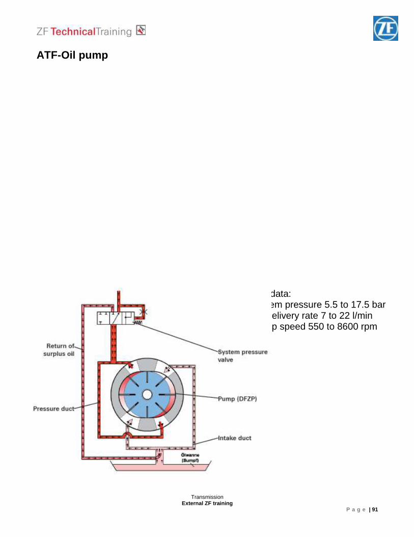
ATF-Oil pump
Technical data: - system pressure 5.5 to 17.5 bar- Oil delivery rate 7 to 22 l/min - Pump speed 550 to 8600 rpm
Transmission External ZF training
P a g e | 92
ATF-Cooling ____________________________________________________________________________________________________________________________________________________________________________________________________________________________________________________________________________________________________________ ____________________________________________________________________________________________________________________________________________________________________________________________________________________________________________________________________________________________________________
Transmission External ZF training
P a g e | 93
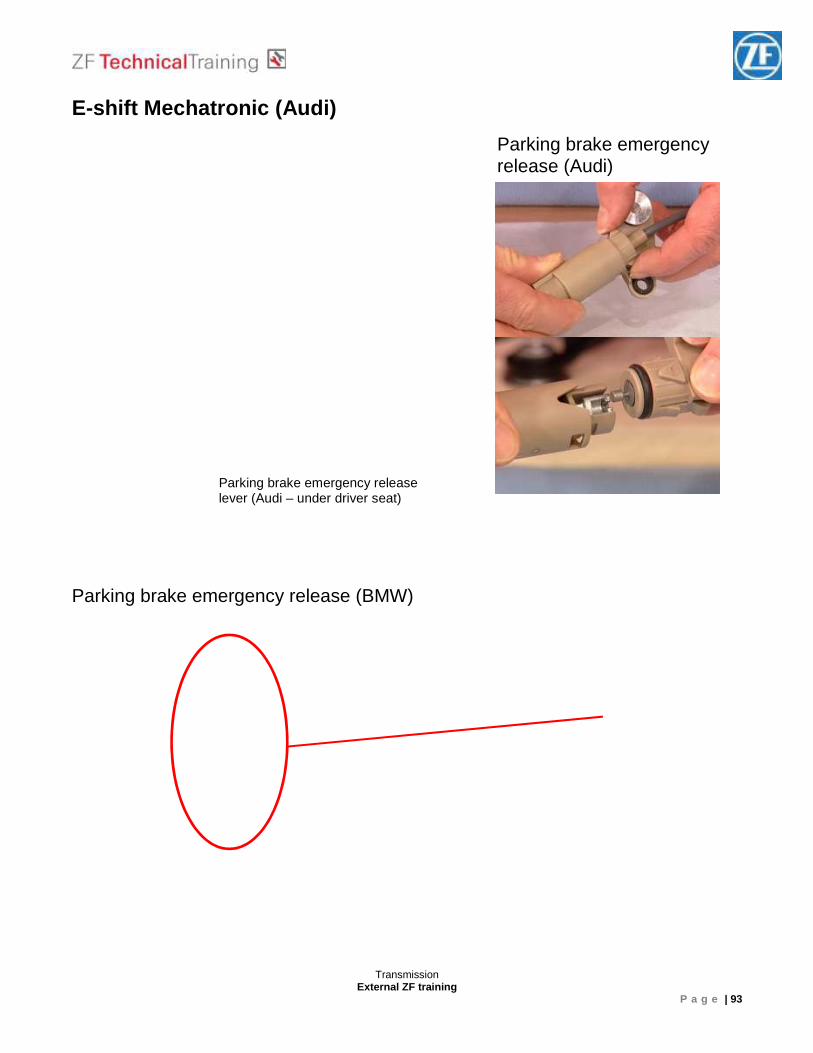
E-shift Mechatronic (Audi) Parking brake emergency release (BMW)
Parking brake emergency release (Audi)
Parking brake emergency release lever (Audi – under driver seat)
Transmission External ZF training
P a g e | 94
Planetary Gear sets / Shift elements ________________________________________________________________________________________________________________________________________________________________________________________________________________________________________________________________________________________________________________________________________________________________________________________________________________________________________________________________________________________________________________________________________________________________________________________________________________________ _____________________________________________________________________________________________________________________________________________________________________________________________________________________________________________________________________________________________________________________________________________________________________________________________________________________________________________________________________________________________________________________________________________
Transmission External ZF training
P a g e | 95
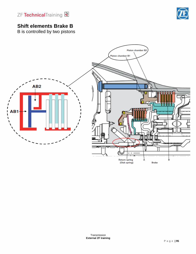
Shift elements Brake B B is controlled by two pistons
Transmission External ZF training
P a g e | 96
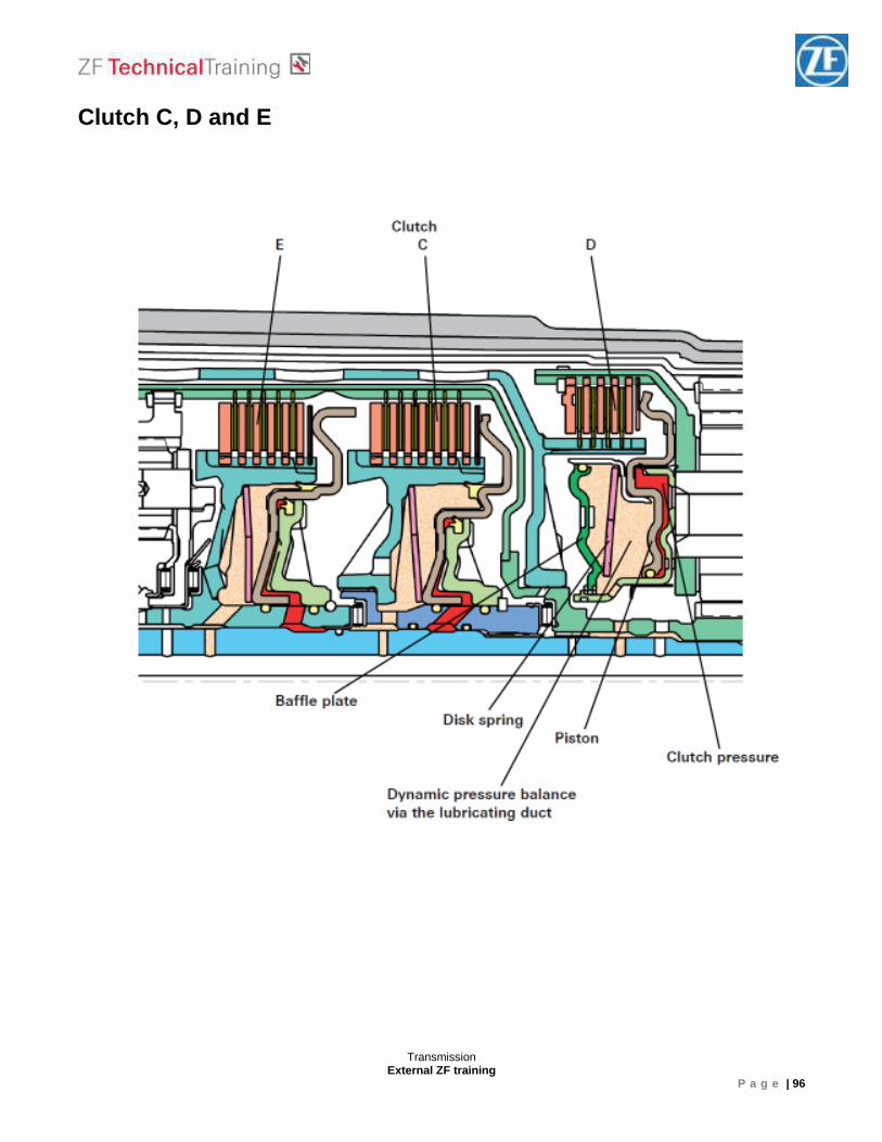
Clutch C, D and E
Transmission External ZF training
P a g e | 97
Planetary Gear sets / Shift elements __________________________________________________________________________________________________________________________________________________________________________________________________________________________________________________________________________________________________________________________________________________________________________________________________________________________________________________________________
Brake A
Brake B
Clutch E
Clutch C
Clutch D
Transmission External ZF training
P a g e | 98
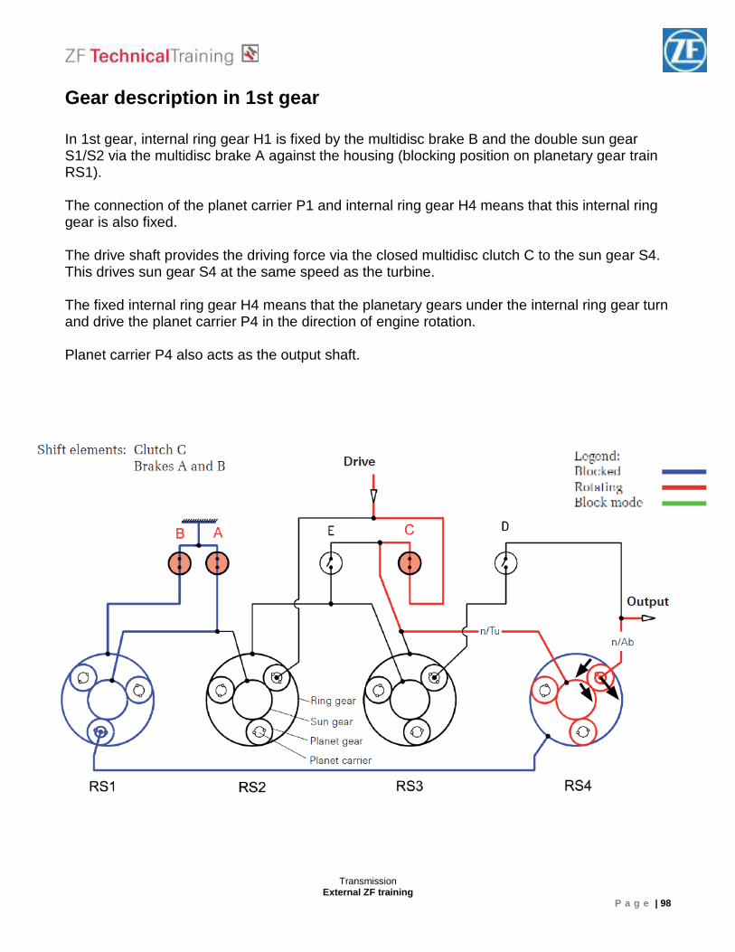
Gear description in 1st gear In 1st gear, internal ring gear H1 is fixed by the multidisc brake B and the double sun gear S1/S2 via the multidisc brake A against the housing (blocking position on planetary gear train RS1). The connection of the planet carrier P1 and internal ring gear H4 means that this internal ring gear is also fixed. The drive shaft provides the driving force via the closed multidisc clutch C to the sun gear S4. This drives sun gear S4 at the same speed as the turbine. The fixed internal ring gear H4 means that the planetary gears under the internal ring gear turn and drive the planet carrier P4 in the direction of engine rotation. Planet carrier P4 also acts as the output shaft.
Transmission External ZF training
P a g e | 99
Gear description in 2nd gear In 2nd gear, internal ring gear H1 is fixed by the multidisc brake B and the double sun gear S1/S2 via the multidisc brake A against the housing (blocking position on planetary gear train RS1). The connection of the planet carrier P1 and internal ring gear H4 means that this gear is also fixed. The drive shaft provides the driving force which drives the planet carrier P2 at the same speed as the turbine. This rolls over the fixed double sun gear S1/S2. This drives the internal ring gear H2 in the direction of engine rotation which in turn drives the sun gear S4 via the closed multidisc clutch E. The fixed internal ring gear H4 means that the planetary gears under the internal ring gear turn and drive the planet carrier P4 in the direction of engine rotation. Planet carrier P4 also acts as the output shaft.
Transmission External ZF training
P a g e | 100
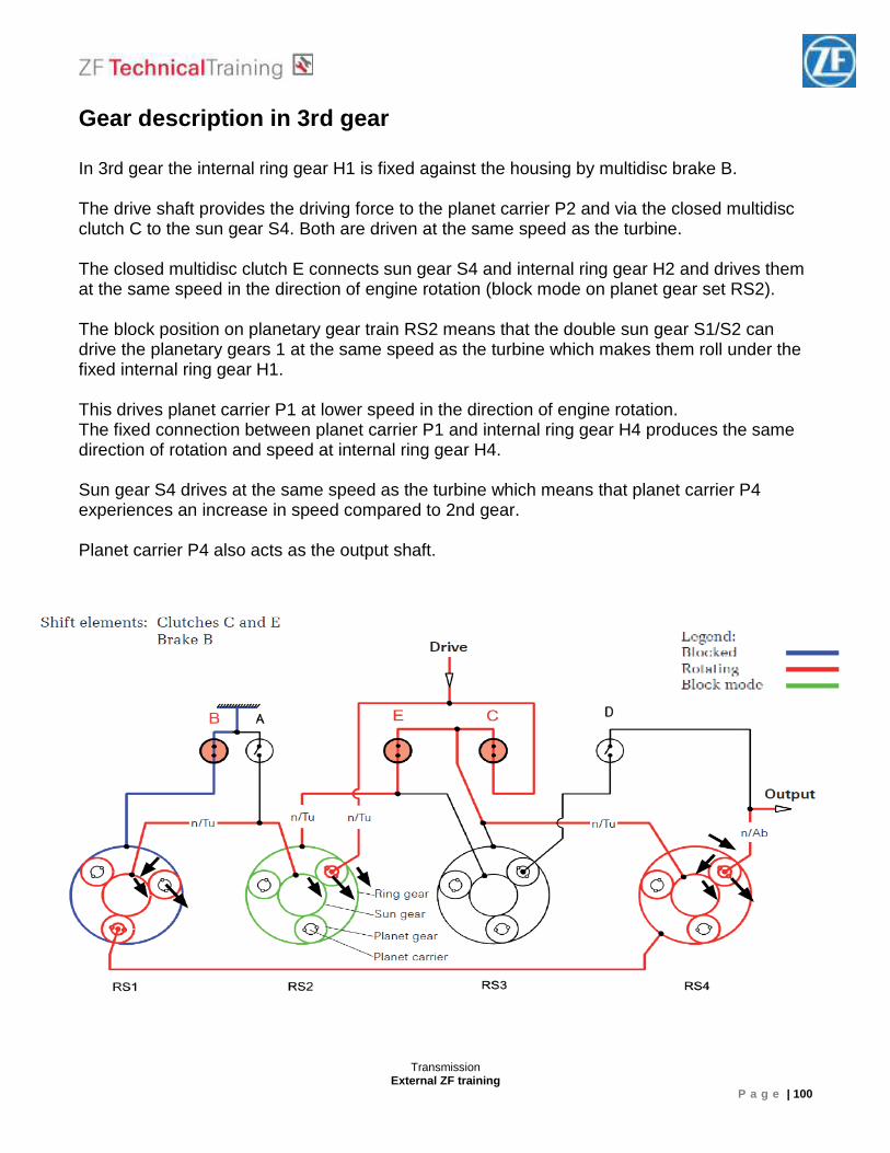
Gear description in 3rd gear In 3rd gear the internal ring gear H1 is fixed against the housing by multidisc brake B. The drive shaft provides the driving force to the planet carrier P2 and via the closed multidisc clutch C to the sun gear S4. Both are driven at the same speed as the turbine. The closed multidisc clutch E connects sun gear S4 and internal ring gear H2 and drives them at the same speed in the direction of engine rotation (block mode on planet gear set RS2). The block position on planetary gear train RS2 means that the double sun gear S1/S2 can drive the planetary gears 1 at the same speed as the turbine which makes them roll under the fixed internal ring gear H1. This drives planet carrier P1 at lower speed in the direction of engine rotation. The fixed connection between planet carrier P1 and internal ring gear H4 produces the same direction of rotation and speed at internal ring gear H4. Sun gear S4 drives at the same speed as the turbine which means that planet carrier P4 experiences an increase in speed compared to 2nd gear. Planet carrier P4 also acts as the output shaft.
Transmission External ZF training
P a g e | 101
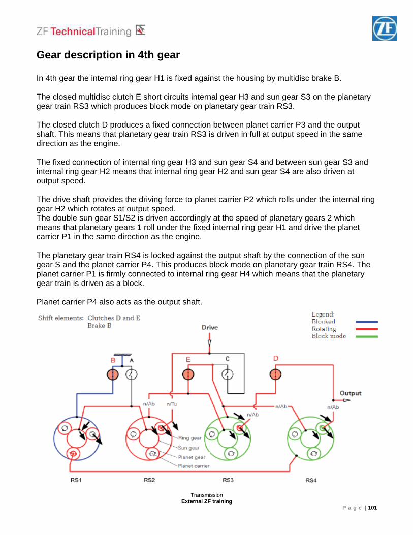
Gear description in 4th gear In 4th gear the internal ring gear H1 is fixed against the housing by multidisc brake B. The closed multidisc clutch E short circuits internal gear H3 and sun gear S3 on the planetary gear train RS3 which produces block mode on planetary gear train RS3. The closed clutch D produces a fixed connection between planet carrier P3 and the output shaft. This means that planetary gear train RS3 is driven in full at output speed in the same direction as the engine. The fixed connection of internal ring gear H3 and sun gear S4 and between sun gear S3 and internal ring gear H2 means that internal ring gear H2 and sun gear S4 are also driven at output speed. The drive shaft provides the driving force to planet carrier P2 which rolls under the internal ring gear H2 which rotates at output speed. The double sun gear S1/S2 is driven accordingly at the speed of planetary gears 2 which means that planetary gears 1 roll under the fixed internal ring gear H1 and drive the planet carrier P1 in the same direction as the engine. The planetary gear train RS4 is locked against the output shaft by the connection of the sun gear S and the planet carrier P4. This produces block mode on planetary gear train RS4. The planet carrier P1 is firmly connected to internal ring gear H4 which means that the planetary gear train is driven as a block. Planet carrier P4 also acts as the output shaft.
Transmission External ZF training
P a g e | 102
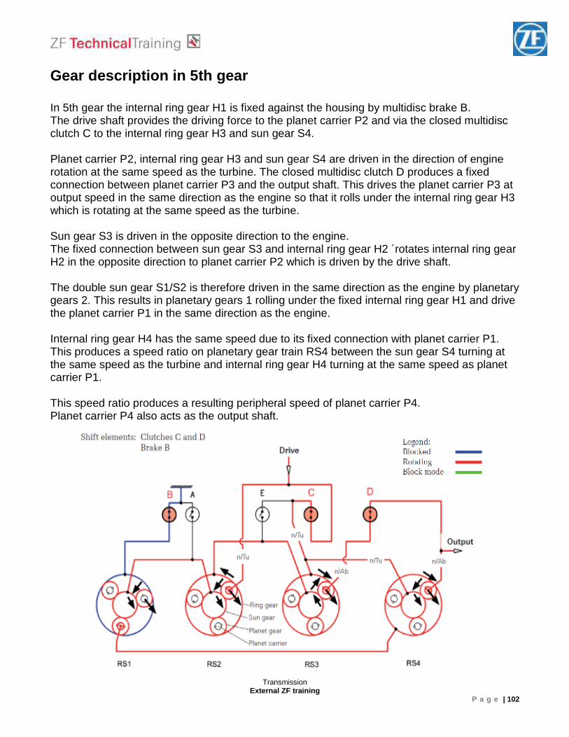
Gear description in 5th gear In 5th gear the internal ring gear H1 is fixed against the housing by multidisc brake B. The drive shaft provides the driving force to the planet carrier P2 and via the closed multidisc clutch C to the internal ring gear H3 and sun gear S4. Planet carrier P2, internal ring gear H3 and sun gear S4 are driven in the direction of engine rotation at the same speed as the turbine. The closed multidisc clutch D produces a fixed connection between planet carrier P3 and the output shaft. This drives the planet carrier P3 at output speed in the same direction as the engine so that it rolls under the internal ring gear H3 which is rotating at the same speed as the turbine. Sun gear S3 is driven in the opposite direction to the engine. The fixed connection between sun gear S3 and internal ring gear H2 ´rotates internal ring gear H2 in the opposite direction to planet carrier P2 which is driven by the drive shaft. The double sun gear S1/S2 is therefore driven in the same direction as the engine by planetary gears 2. This results in planetary gears 1 rolling under the fixed internal ring gear H1 and drive the planet carrier P1 in the same direction as the engine. Internal ring gear H4 has the same speed due to its fixed connection with planet carrier P1. This produces a speed ratio on planetary gear train RS4 between the sun gear S4 turning at the same speed as the turbine and internal ring gear H4 turning at the same speed as planet carrier P1. This speed ratio produces a resulting peripheral speed of planet carrier P4. Planet carrier P4 also acts as the output shaft.
Transmission External ZF training
P a g e | 103
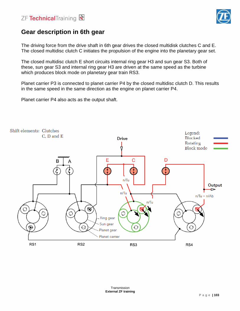
Gear description in 6th gear The driving force from the drive shaft in 6th gear drives the closed multidisk clutches C and E. The closed multidisc clutch C initiates the propulsion of the engine into the planetary gear set. The closed multidisc clutch E short circuits internal ring gear H3 and sun gear S3. Both of these, sun gear S3 and internal ring gear H3 are driven at the same speed as the turbine which produces block mode on planetary gear train RS3. Planet carrier P3 is connected to planet carrier P4 by the closed multidisc clutch D. This results in the same speed in the same direction as the engine on planet carrier P4. Planet carrier P4 also acts as the output shaft.
Transmission External ZF training
P a g e | 104
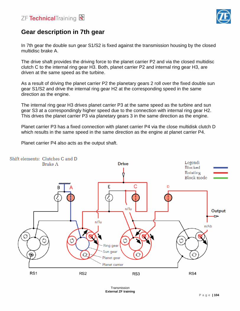
Gear description in 7th gear In 7th gear the double sun gear S1/S2 is fixed against the transmission housing by the closed multidisc brake A. The drive shaft provides the driving force to the planet carrier P2 and via the closed multidisc clutch C to the internal ring gear H3. Both, planet carrier P2 and internal ring gear H3, are driven at the same speed as the turbine. As a result of driving the planet carrier P2 the planetary gears 2 roll over the fixed double sun gear S1/S2 and drive the internal ring gear H2 at the corresponding speed in the same direction as the engine. The internal ring gear H3 drives planet carrier P3 at the same speed as the turbine and sun gear S3 at a correspondingly higher speed due to the connection with internal ring gear H2. This drives the planet carrier P3 via planetary gears 3 in the same direction as the engine. Planet carrier P3 has a fixed connection with planet carrier P4 via the close multidisk clutch D which results in the same speed in the same direction as the engine at planet carrier P4. Planet carrier P4 also acts as the output shaft.
Transmission External ZF training
P a g e | 105
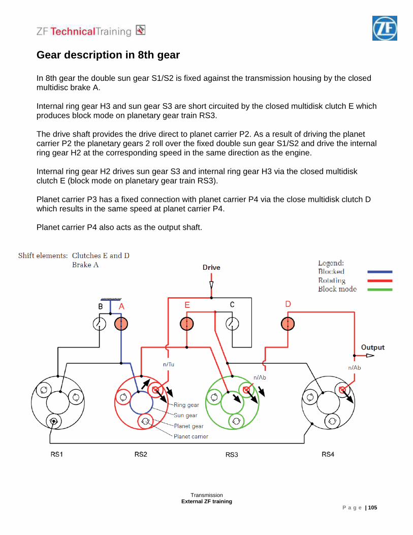
Gear description in 8th gear In 8th gear the double sun gear S1/S2 is fixed against the transmission housing by the closed multidisc brake A. Internal ring gear H3 and sun gear S3 are short circuited by the closed multidisk clutch E which produces block mode on planetary gear train RS3. The drive shaft provides the drive direct to planet carrier P2. As a result of driving the planet carrier P2 the planetary gears 2 roll over the fixed double sun gear S1/S2 and drive the internal ring gear H2 at the corresponding speed in the same direction as the engine. Internal ring gear H2 drives sun gear S3 and internal ring gear H3 via the closed multidisk clutch E (block mode on planetary gear train RS3). Planet carrier P3 has a fixed connection with planet carrier P4 via the close multidisk clutch D which results in the same speed at planet carrier P4. Planet carrier P4 also acts as the output shaft.
Transmission External ZF training
P a g e | 106
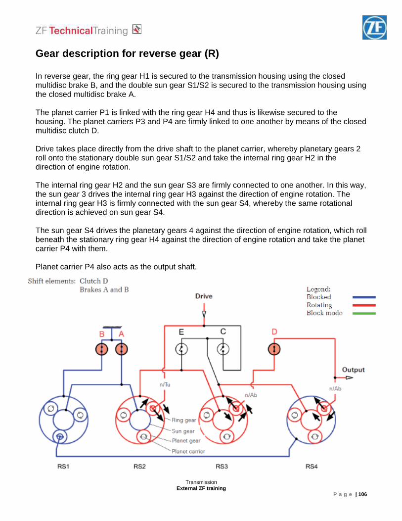
Gear description for reverse gear (R) In reverse gear, the ring gear H1 is secured to the transmission housing using the closed multidisc brake B, and the double sun gear S1/S2 is secured to the transmission housing using the closed multidisc brake A. The planet carrier P1 is linked with the ring gear H4 and thus is likewise secured to the housing. The planet carriers P3 and P4 are firmly linked to one another by means of the closed multidisc clutch D. Drive takes place directly from the drive shaft to the planet carrier, whereby planetary gears 2 roll onto the stationary double sun gear S1/S2 and take the internal ring gear H2 in the direction of engine rotation. The internal ring gear H2 and the sun gear S3 are firmly connected to one another. In this way, the sun gear 3 drives the internal ring gear H3 against the direction of engine rotation. The internal ring gear H3 is firmly connected with the sun gear S4, whereby the same rotational direction is achieved on sun gear S4. The sun gear S4 drives the planetary gears 4 against the direction of engine rotation, which roll beneath the stationary ring gear H4 against the direction of engine rotation and take the planet carrier P4 with them. Planet carrier P4 also acts as the output shaft.
Transmission External ZF training
P a g e | 107
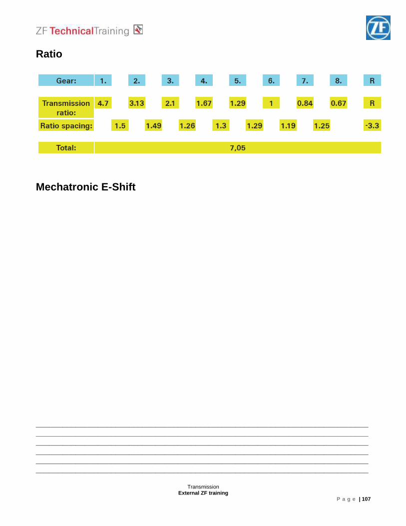
Ratio
Mechatronic E-Shift ____________________________________________________________________________________________________________________________________________________________________________________________________________________________________________________________________________________________________________ ______________________________________________________________________________________________________________________________________________________
Transmission External ZF training
P a g e | 108
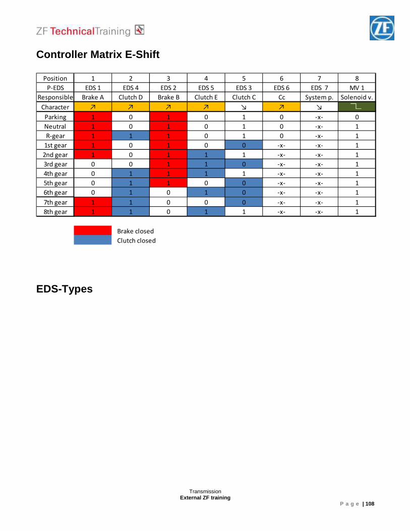
Controller Matrix E-Shift EDS-Types
Position 1 2 3 4 5 6 7 8
P-EDS EDS 1 EDS 4 EDS 2 EDS 5 EDS 3 EDS 6 EDS 7 MV 1
Responsible Brake A Clutch D Brake B Clutch E Clutch C Cc System p. Solenoid v.
Character ↗ ↗ ↗ ↗ ↘ ↗ ↘
Parking 1 0 1 0 1 0 -x- 0
Neutral 1 0 1 0 1 0 -x- 1
R-gear 1 1 1 0 1 0 -x- 1
1st gear 1 0 1 0 0 -x- -x- 1
2nd gear 1 0 1 1 1 -x- -x- 1
3rd gear 0 0 1 1 0 -x- -x- 1
4th gear 0 1 1 1 1 -x- -x- 1
5th gear 0 1 1 0 0 -x- -x- 1
6th gear 0 1 0 1 0 -x- -x- 1
7th gear 1 1 0 0 0 -x- -x- 1
8th gear 1 1 0 1 1 -x- -x- 1
Brake closed
Clutch closed
Transmission External ZF training
P a g e | 109
Position of the Mechatronic pressure channel
Transmission External ZF training
P a g e | 110
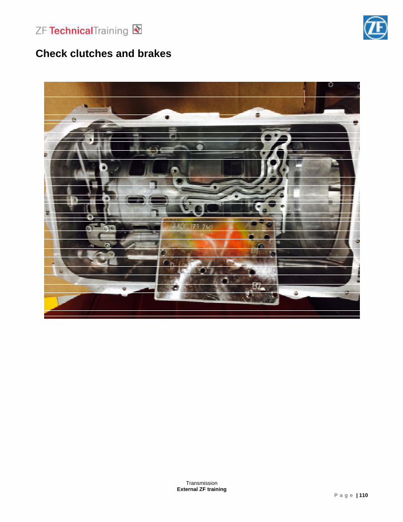
Check clutches and brakes
Transmission External ZF training
P a g e | 111
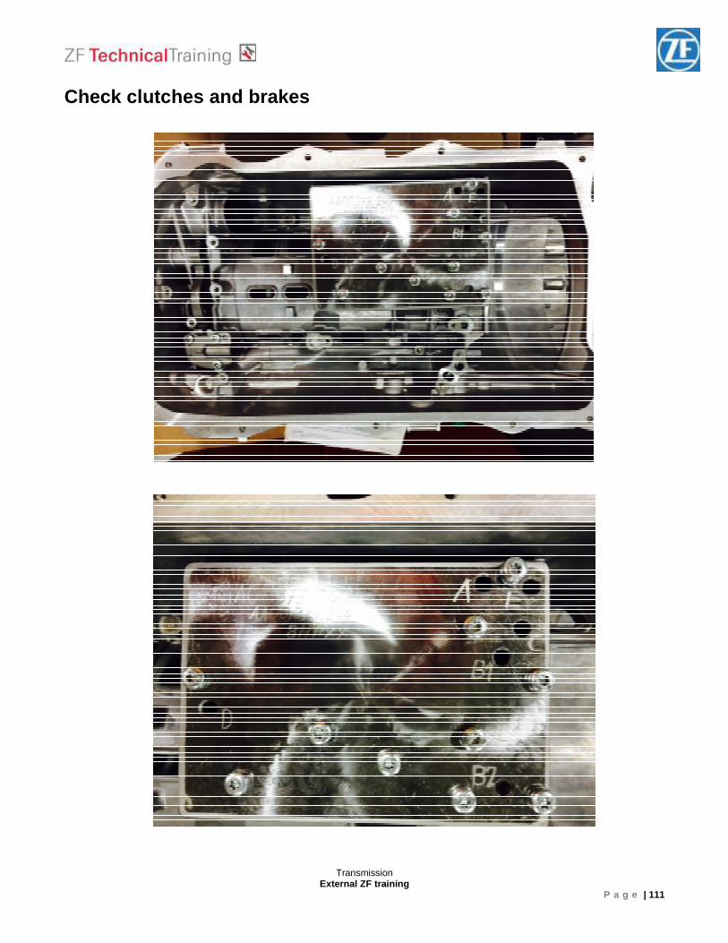
Check clutches and brakes
Transmission External ZF training
P a g e | 112
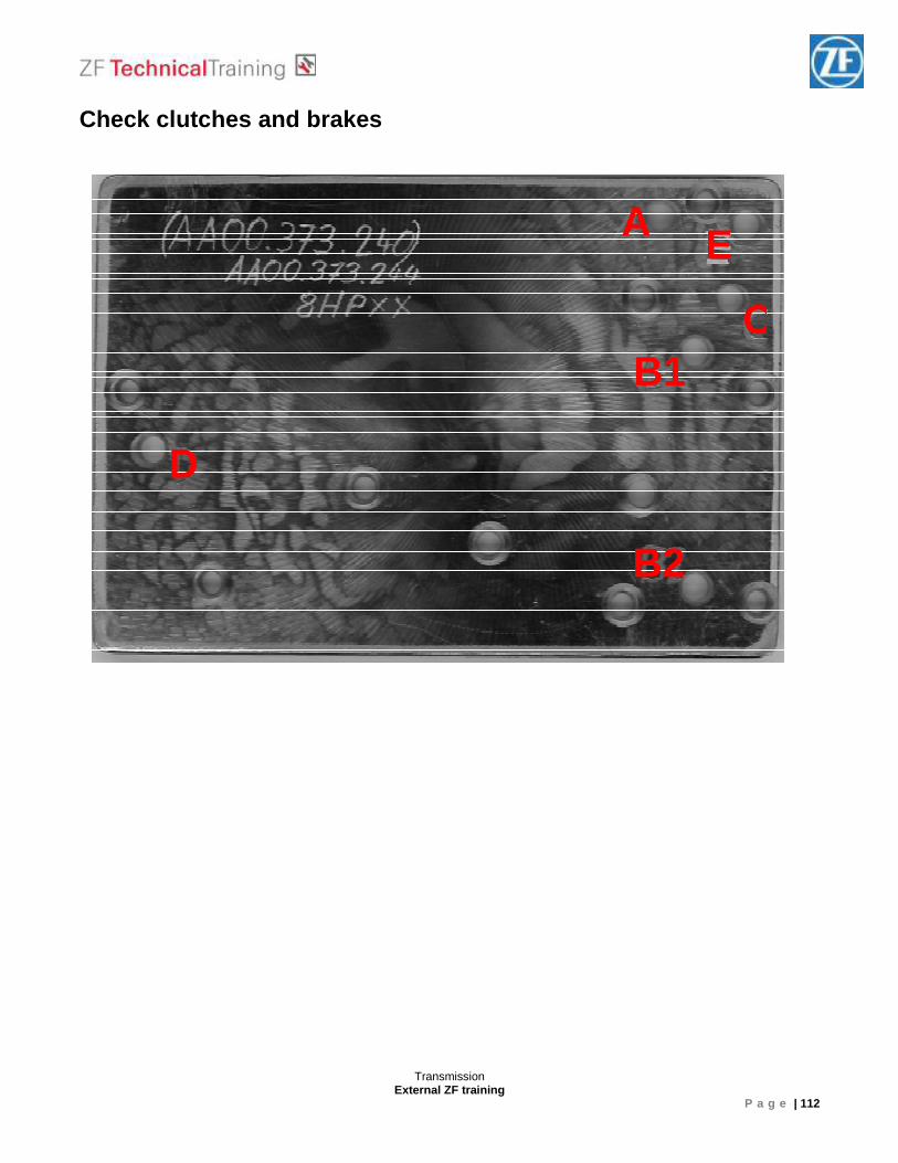
Check clutches and brakes
A E
CB1
B2
D
Transmission External ZF training
P a g e | 113
Template for the tool
Transmission External ZF training
P a g e | 114
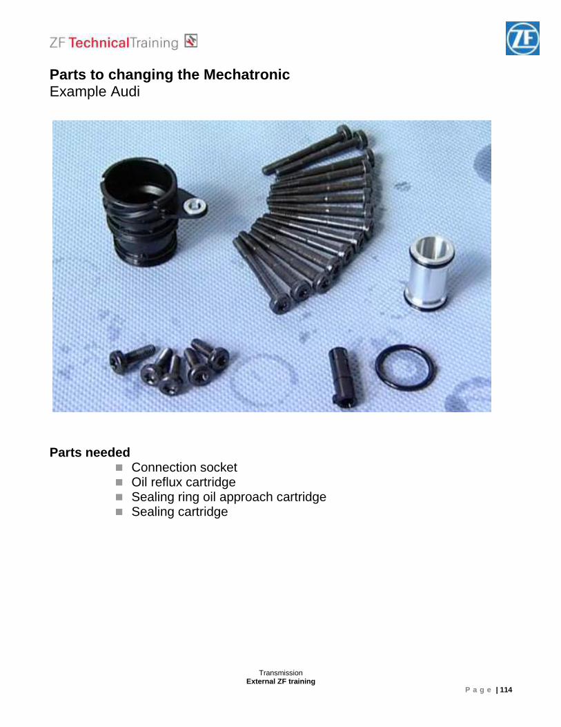
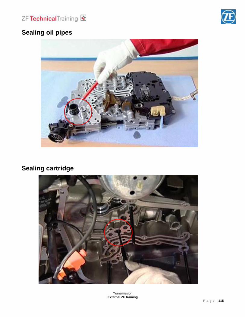
Parts to changing the Mechatronic Example Audi
Parts needed � Connection socket � Oil reflux cartridge � Sealing ring oil approach cartridge � Sealing cartridge
Transmission External ZF training
P a g e | 115
Sealing oil pipes
Sealing cartridge
Transmission External ZF training
P a g e | 116
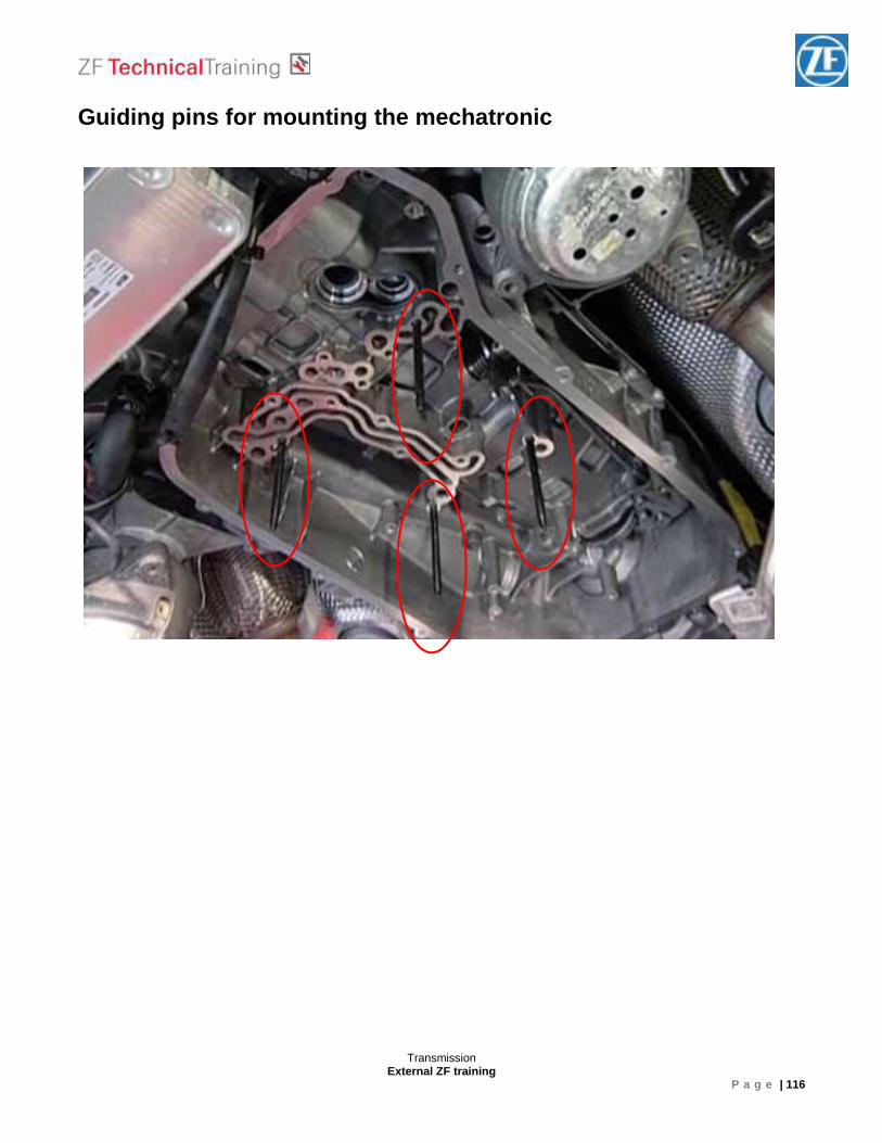
Guiding pins for mounting the mechatronic
Transmission External ZF training
P a g e | 117
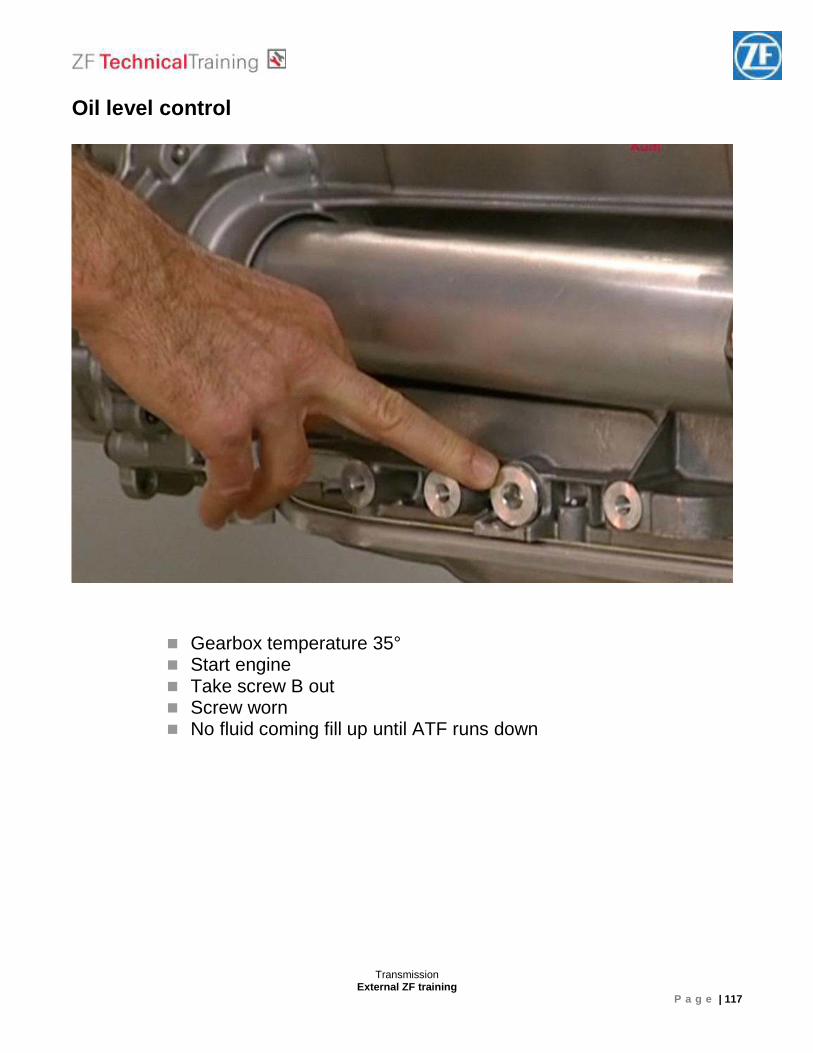
Oil level control
� Gearbox temperature 35° � Start engine � Take screw B out � Screw worn � No fluid coming fill up until ATF runs down
Transmission External ZF training
P a g e | 118
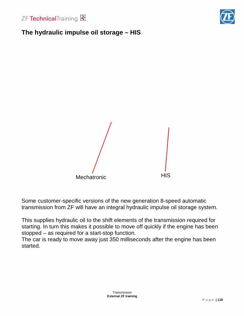
The hydraulic impulse oil storage – HIS Some customer-specific versions of the new generation 8-speed automatic transmission from ZF will have an integral hydraulic impulse oil storage system. This supplies hydraulic oil to the shift elements of the transmission required for starting. In turn this makes it possible to move off quickly if the engine has been stopped – as required for a start-stop function. The car is ready to move away just 350 milliseconds after the engine has been started.
Mechatronic HIS
Transmission External ZF training
P a g e | 119
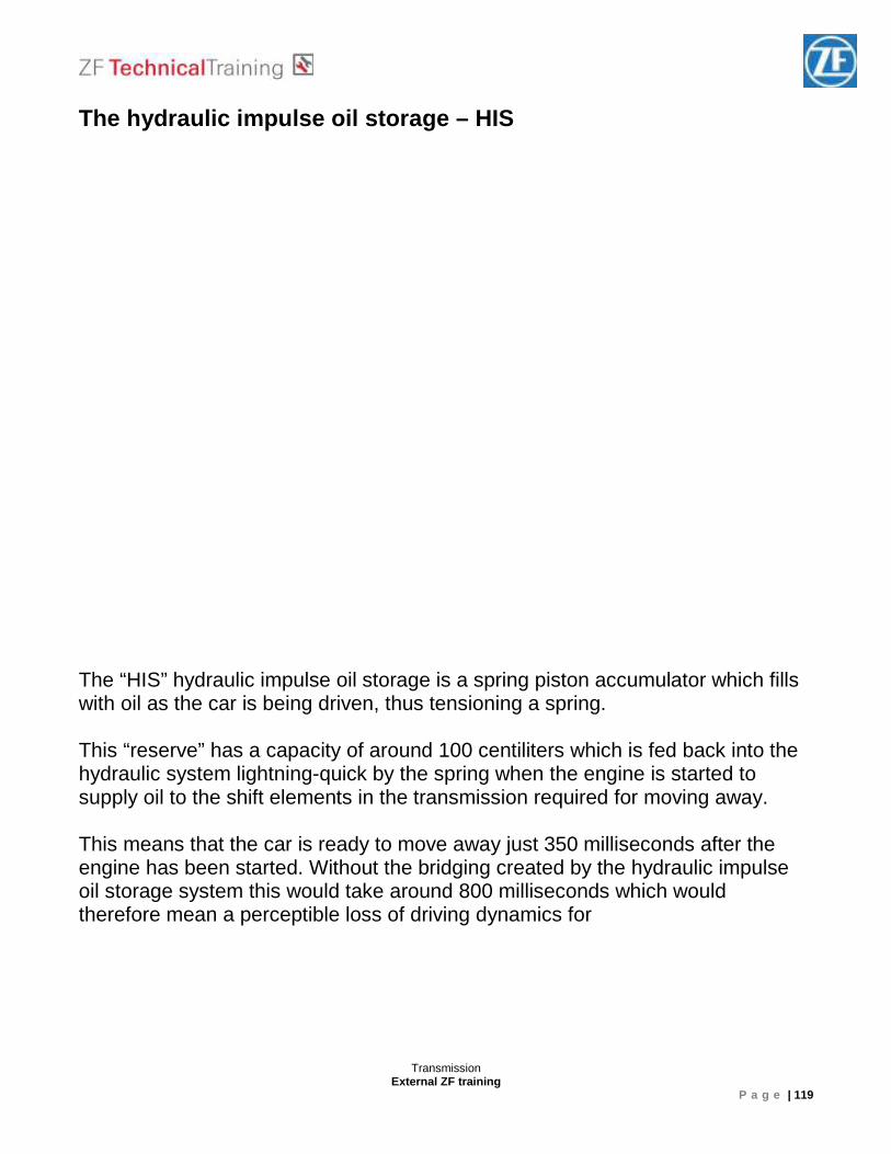
The hydraulic impulse oil storage – HIS The “HIS” hydraulic impulse oil storage is a spring piston accumulator which fills with oil as the car is being driven, thus tensioning a spring. This “reserve” has a capacity of around 100 centiliters which is fed back into the hydraulic system lightning-quick by the spring when the engine is started to supply oil to the shift elements in the transmission required for moving away. This means that the car is ready to move away just 350 milliseconds after the engine has been started. Without the bridging created by the hydraulic impulse oil storage system this would take around 800 milliseconds which would therefore mean a perceptible loss of driving dynamics for
Transmission External ZF training
P a g e | 120
The hydraulic impulse oil storage – HIS
Solenoid not
energized
Transmission External ZF training
P a g e | 121
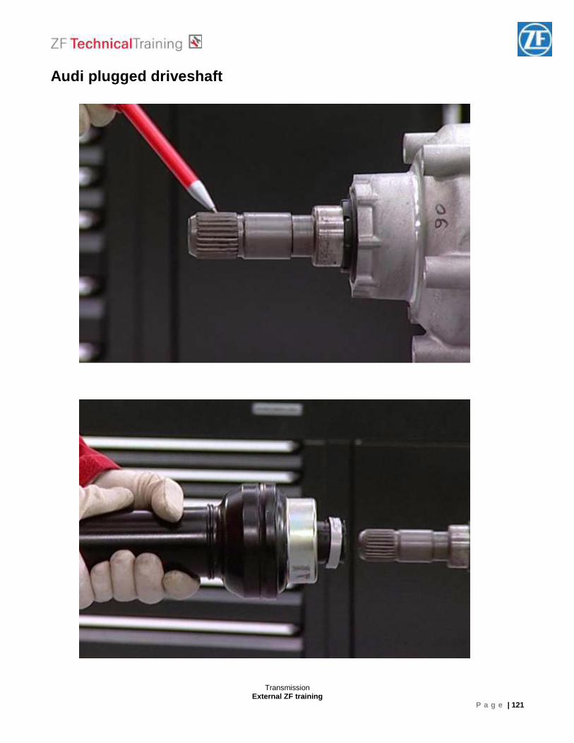
Audi plugged driveshaft
Transmission External ZF training
P a g e | 122
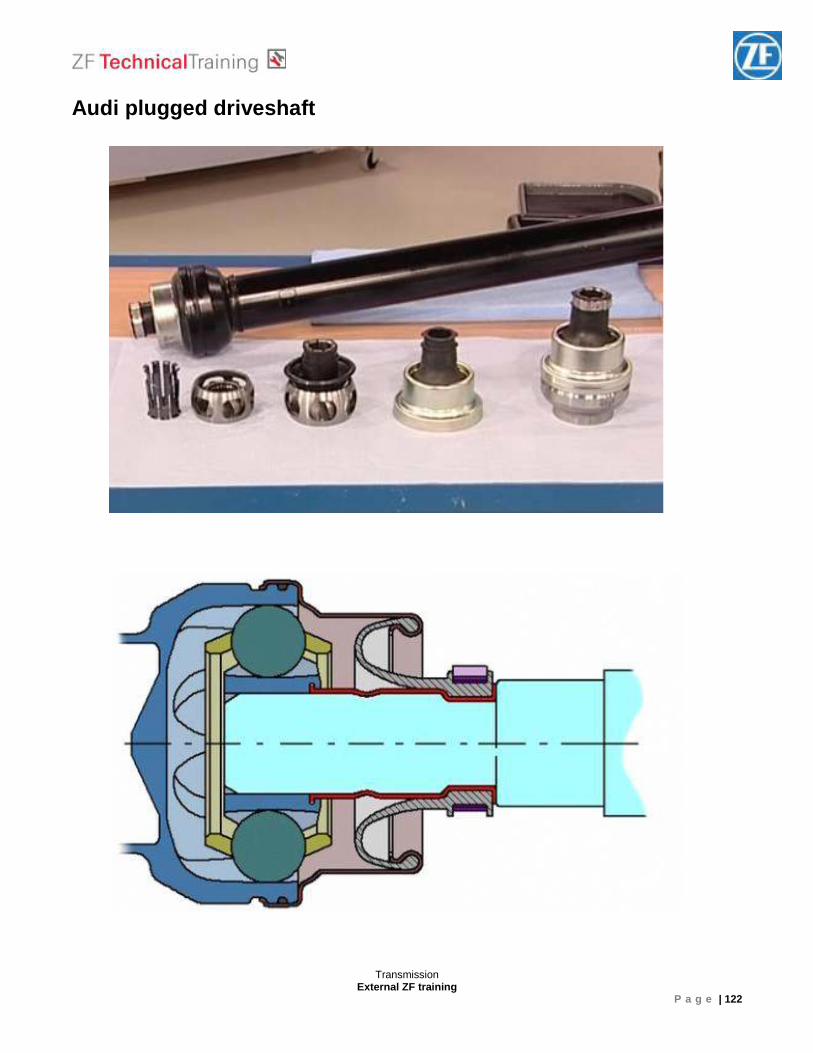
Audi plugged driveshaft
Transmission External ZF training
P a g e | 123
Vehicle for 8HP Transmission BMW group
Transmission External ZF training
P a g e | 124
Jaguar & Land Rover
Fiat group
Transmission External ZF training
P a g e | 125
Volkswagen group
Transmission External ZF training
P a g e | 126
Identification of the Transmission ____________________________________________________________________________________________________________________________________________________________________________________________________________________________________________________________________________________________________________ ____________________________________________________________________________________________________________________________________________________________________________________________________________________________________________________________________________________________________________ ____________________________________________________________________________________________________________________________________________________________________________________________________________________________________________________________________________________________________________ ____________________________________________________________________________________________________________________________________________________________________________________________________________________________________________________________________________________________________________
Transmission External ZF training
P a g e | 127
Troubleshooting While freewheeling and changing from second into first gear (for example when approaching traffic lights) a kick happens. Check play on the flex disc _________________________________________________________________________________________________________________________________________________________________________________________________________________________________ ____________________________________________________________________________________________________________________________________________________________________________________________________________________________________________________________________________________________________________
Transmission External ZF training
P a g e | 128
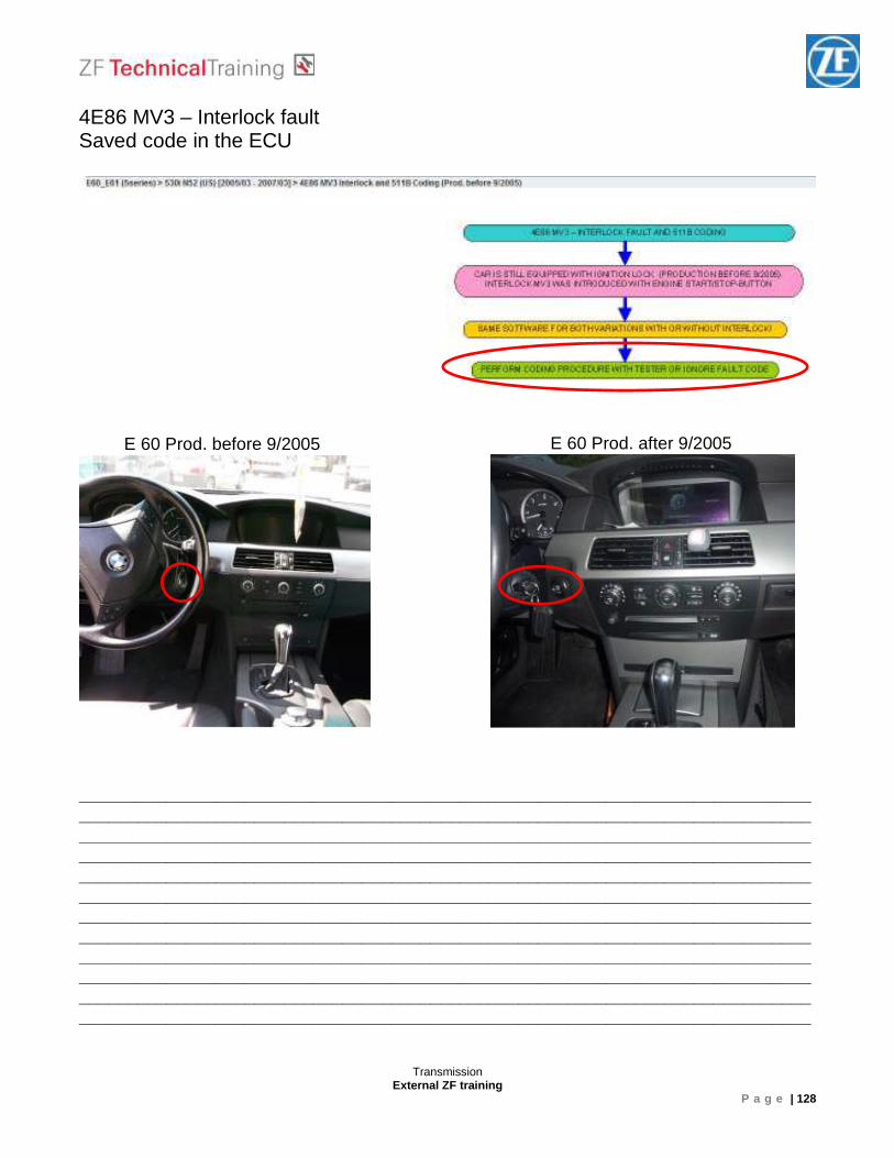
4E86 MV3 – Interlock fault Saved code in the ECU _________________________________________________________________________________________________________________________________________________________________________________________________________________________________ ____________________________________________________________________________________________________________________________________________________________________________________________________________________________________________________________________________________________________________ _________________________________________________________________________________________________________________________________________________________________________________________________________________________________ ______________________________________________________________________________________________________________________________________________________
E 60 Prod. before 9/2005 E 60 Prod. after 9/2005
Transmission External ZF training
P a g e | 129
Towing in case of breakdown Audi towing The vehicle can be towed at a maximum vehicle speed of 50 km/h over a maximum distance of 50 km using the drive wheels. The transmission must be mechanically unlocked. That means: The parking lock must be released by means of a Bowden cable. The automatic transmission can be seriously damaged if the above-mentioned boundary values are not maintained. BMW towing The precondition for towing a vehicle with an unraised drive axle is that the parking lock be opened by means of a Bowden cable emergency release. If this is the case, towing with a maximum speed of 50 km/h over a maximum distance of 50 km is possible. The automatic transmission can be seriously damaged if the above-mentioned boundary values are not maintained. Vehicles on which the parking lock must be opened with an unlocking screw cannot be towed. In case of breakdown, the vehicle must be raised with a crane and delivered to the workshop for repair on a flatbed tow truck. Four-wheel-driven vehicles Vehicles with four-wheel drive must not be towed with one axle lifted.
Transmission External ZF training
P a g e | 130
Pushing The engine cannot be started by pushing the vehicle. That is to say, if the engine is stopped, there is no transmission of power from the hydrodynamic coupling of the engine and transmission and the pressure-less shift elements.

Transmission External ZF training
P a g e | 131

Transmission External ZF training
P a g e | 132


