IWG-LMNPP-97/3<V. LIMITED DISTRIBUTION XA9949577- ff WORKING MATERIAL International Working Group on Life Management of Nuclear Power Plants. (IWG-LMNPP) Regular Meeting 6 - 8 October 1997, IAEA Headquarters, Vienna, Austria. Volume II Reproduced by the IAEA Vienna, Austria, 1998 NOTE The material in this document has been supplied by the authors and has not been edited by the IAEA. The views expressed remain the responsibility of the named authors and do not necessarily reflect those of the government(s) of the designating Member State(s). In particular, neither the IAEA nor any other organization or body sponsoring this meeting can be held responsible for any material reproduced in this document. 30- 14
Transcript
IWG-LMNPP-97/3<V.LIMITED DISTRIBUTION
XA9949577- ff
WORKING MATERIAL
International Working Group on LifeManagement of Nuclear Power Plants.
(IWG-LMNPP)
Regular Meeting
6 - 8 October 1997, IAEA Headquarters,Vienna, Austria.
Volume II
Reproduced by the IAEAVienna, Austria, 1998
NOTEThe material in this document has been supplied by the authors and has not been edited bythe IAEA. The views expressed remain the responsibility of the named authors and do notnecessarily reflect those of the government(s) of the designating Member State(s). Inparticular, neither the IAEA nor any other organization or body sponsoring this meeting canbe held responsible for any material reproduced in this document.
3 0 - 14
DISCLAIMER
Portions of this document may beillegible in electronic image products-Images are produced from the best
available original document.
C o n t e n t s
Volume 1
I. Opening Page
1. Summary of the Meeting 32. Opening speech by Mr. P.E.-Juhn 63. Opening speech by Mr.B.Gueorguiev 94. Opening remarks by Mr.L.M.Davies, Chairman 115. Report on the IWG - LMNPP activities, V.Lyssakov,
Scientific Secretary of the IWG-LMNPP 12
n. National Reports
Argentina 25Brazil 31Belgium 49Canada 70Czech Republic 93Finland 141France 301Germany 307
1. Terms of Reference and the Scope of Activities 2912. List of Meetings for the period 1998 - 2000 2983. Scope of the Meetings 299
V. Appendices 307
Appendix 1 - Agenda of the Meeting 308Appendix 2 - List of Participants 310Appendix 3 - Minutes of the Meeting 323Appendix 4 - The Approach Associated with the Continued
Operation Calder Hall and Chapelcross NuclearPower Stations to 50 years 327
- 2 -
Meeting of the International Working Group on Life Management ofNuclear Power Plants.
II. National Reports
( continued)
6-8 October 1997, Vienna, Austria.
- 3 -
XA9949578
[ AEKI
NATIONAL REPORT
Recent development in Life Management of the PressurisedComponents
by: F. Gillemot*
Atomic Energy Research InstituteBudapest, Hungary
Technical Committee Meeting of the International Working Group onLife Management of Nuclear Power Plants
Vienna 6-8 October 1997.
- 4 -
NPP LIFE MANAGEMENT in HUNGARY
by
Ferenc Gillemot
Atomic Energy Research Institute, Budapest
1. Introduction.
When NPP Paks was built (during the end of the 70-s) -like everywhere- the basic idea inHungary was to build a power plant, which is able to be operated safely for 30 years.Although no life management plan wasnot elaborated during the construction period, theinvestors, the Hungarian electricity board and the co-operating research institutes took manysteps forming the basis of the Life Management of NPP Paks.
After the start-up of the 4th Unit of the plant, the research organisations in Hungary startedto concentrate their resources on increasing the level of safety and on dealing with theproblems of life extension [1-4].
2. Present developments and actions
The present developments in the field of Life Management and Safety can be divided intofour groups:
• Governmental actions
• Regulatory actions
• Utility actions
• R&D
2. 1. Governmental actions
• New law on peaceful use of nuclear energy was accepted by the parliament (itrequires to present a new periodic safety report for every nuclear units in each 10years period of operation. On evaluation of these reports the authority can extendthe operational licenses for the next 10 years period)
• The Nuclear Regulatory Body and the National Committee of Atomic Energy hadbeen reorganised
National report of Hungary 1997TCM IAEA IWG LMNPP
- 5 -
2.2. Nuclear Regulatory Committee actions
• New national Code of Safety had been issued (it based on the ASME and on thepresent issue of the Russian Code PNAE. Finnish experience is widely used duringelaborating of it.)
• The first periodic safety reports were evaluated and the licences of the Paks unit 1and 2 were issued for the next 10 years
• The Regulatory Committee initiated and sponsoring the elaboration of a serie ofstudies and guides on ageing evaluation and management.
2.3. Utility actions.
NPP Paks elaborated and presented the first periodic safety reports to the authority
• Life management program was started
• Several safety enhance actions started (Fire insulation's of cables, updating thecomputer systems, inserting safety valves for automatic protection against coldover-pressurising etc.)
• Enhanced condensers were built into secondary circuits to increase the efficiency
• Revision of the operation instructions according to the enhanced safetyrequirements of the new national Code
• Enhancements ofthelSI equipment's
• Surveillance program extensions
• Built up a new training centre
2.4 Research actions
• study of thermal ageing of 15H2MFA steel and of the cladding properties
• development of the PTS methodology
• participation in the IAEA co-ordinated research programmes on use of Mastercurve
• study of the properties of the welding of WWER-440 reactors
• Round-Robin on the use of the new IAEA PTS guide
• elaboration of FM method for crack arrest measurement on small size specimens
• elaboration of national database on RPV materials and management of the IAEARPV database
The short description of some utility and research actions are given below.
National report of Hungary 1997TCM IAEA IWG LMNPP
- 6 -
3. Overview of PTS methodology used at NPP Paks
The PTS assessment includes several separated actions as shown in FIG. 1.
System analysis
Material properties PTS selection
Surveillance results
RPV geometry
One dimensional determinsiticanalysis.
Stage
ISI results
Hypotethical defect selection
End
3D finite element analysis
Stage II
Sf>1.0 End
Crack arrest calculation
Stage I
a<0.75w End
Probabilistic approach
Stage IVp<5*10"6year End
FIG. 1. The flowchart of the PTS assessment in the frame of the AGNES project.
These actions were performed by different groups of engineers and scientists, and wereco-ordinated by the manager of the AGNES project. The main actions are further discussedbelow:
National report of Hungary 1997TCM IAEA IWG LMNPP
- 7 -
3.1. Transients selection
The selection of the transients to be analysed is the most difficult part of the analysis.The selection needs good knowledge of the reactor system, and analysis of the plant specificbehaviour upon in view of the transients. Many transients are plant specific, that is they canoccur at one plant, but are not typical for another similar plant operated in a different way, orlocated at another site, where the weather conditions are different. Generally the so calledsimilar plants only mean plant specific equipment, and during operation the operational modeand maintenance history are very often different even in case of the units of the same plant. Inthe frame of the AGNES project the PTS transient pressure, temperature data are alwaysbased on thermohydraulic transient simulation, which incorporates the unit specificcharacteristics. The calculations not only contain the effect of the overcooling-depressurization event, but repressurisation-reheating situations are also considered.Altogether 7 transients with 18 cases were analysed. Case means here different operatoractions after the same transient event started or variations of the transient according torandom behaviour of the damaged equipment. (E.g. after the inadvertent opening of the safetyvalve it automatically closes again after a certain time.) The selected transients are given intable 1.
TABLE 1. The tested transients.
Transient name
Inadvertent Opening of the Pressuriser Safety Valve
Opening of Steam Generator Cover.
Line break 0 233
Line break 0 73
Cold leg large break LOCA
Inadvertent Operation of the Emergency Core Cooling System
Steam line break
Total: 7 transients
Cases
4
3
1
3
3
2
2
18
3.2 RPV geometry
Paks units 1-4 are WWER-440 V-213 pressure vessels. The main characteristics of theV-213 vessels are:
• the vessel is welded from forged rings, it has an inside cladding made bysubmerged arc strip welding. Inner diameter: 3542 mm.
• the base material is 140 mm thick against the core zone, and 190 mm at the nozzlezone. The material is 15H2MFA. The cladding is 9 mm thick welded 18/8 typestainless steel.: 08H18N12B.
• The most critical parts of the pressure vessels (because of the highest neutron flux)are the welds 5/6, 3/5 and the forged ring against the core. Optionally the nozzlezone may be considered for analysis.
3.3 Thermohydraulic calculations
Most of the thermohydraulic analyses were performed by RELAP 5 code. The code hadbeen modified to model the 6 loop WWER-440 design. The water mixing in the downcommerhad also been considered in several cases using REMIX code.
National report of Hungary 1997TCM IAEA IWG LMNPP
- 8 -
3.4 Material database
All four units of NPP Paks have complete manufacturer documentation includingmaterial properties, production technology and quality assurance. These data were validatedby the NPP owner during installation. Surveillance testing of the vessel material includingsurveillance of radiation embrittlement and thermal ageing were performed parallel with I SItesting. The operational parameters has been also monitored. These databases and theknowledge of 15H2MFA steel properties gained from international co-operation and from theresearch performed in Hungary make a reliable integrity assessment during any possible PTS.
During the different stages of the fracture mechanical integrity analysis of the RPVdifferent material characteristics are used. For the analysis of crack stability (no initiation) theKlc reference curve is used, for calculation of arrest of a propagating crack the crack arrestreference (Klaor K^) curve is needed.
Klc reference curve
In case of the Paks units both the forged material and the welding satisfies the updatedrequirements of 15H2MFA steel, and this verifies the use of the new reference curves for PTSevents given in the Russian Normative Documents [8]:
where TK is the transition temperature measured by Charpy impact testing belonging tounirradiated (Tk0) or irradiated (T^) values. The TK0 values are given by the producer, and theTjy values are calculated from the unit surveillance results. The reference curves werecompared with the results obtained on Charpy size TBP specimens of the surveillanceprogram as it shown on FIG.2.
A orging re ference a ove
50-weim, ig referet ce curve
-100 -50 0 50 100
Temperature fiCJ
150
FIG. 2. Comparison of theK1c reference curves andsurveillance resultsobtained on weldmentsamples.
National report of Hungary 1997TCM IAEA IWG LMNPP
- 9 -
Crack arrest (KQ reference curve
For the 15H2MFA steel and weldment no Ku reference curves are available in the Rulesor in the Russian Normative Documents. Instead of it the ASME KIR (Reference FractureToughness) curve was used . The KIR curve represents the lower bound critical stress intensityfactors determined from static, dynamic and crack arrest curves. According to the ASMECode the KIR is a function of temperature and RTNDT (Nil-ductility temperature obtained bydrop-weight test). The RTNDT values can also be calculated from the surveillance impacttesting results. The RTNDTO value (belonging to as received material) is TKO-33 °C where TKois determined using 68 J criteria. The RTNDTJ (belonging to irradiated material) value isRTNDTO+ ATTKV41, where ATTKV41 is the irradiation caused temperature shift measured with41J criteria.
To verify the use of the ASME KIR curve the instrumented impact diagrams measuredduring the surveillance testing of NPP Paks on 15H2MFA steel were analysed and comparedwith the results obtained. Kia values on 15H2MFA forging were measured in the frame of theOMFB (National Committee on R&D) financed research project "Radiation damage of15H2MFA steel" (91-97-42-0339).
3.5 Selection of hypotethycal defects
According to the Russian Code which was valid at the beginning of the AGNES project,and international studies [4,5] the following three models were selected for study.
Model 1.:Axial semielliptical surface crack a/c=2/3, depth is 1/4T = 35 mm. Location: theforging against the middle of the core.Model 2.: Underclad axial crack in the ferritic welds, 4 mm deep and 50 mm longtouching the interface of the clad, which is in complete contact with the vessel wall, andfree of defects. Location: weld 5/6; weld 3/5.Model 3.: Elliptical circumferential surface crack with a depth of 4 mm in the 15H2MFAweldment, and the clad is postulated broken (i.e. Sdepth=13 mm), a/c=2/3. Location:weld 5/6; weld 3/5.
3.6 Organisation of the FM (fracture mechanics) analysis
The selected 18 cases multiplied with three crack models result in 54 FM analyses to beperformed. Even if the temperature and stress distribution is common in some cases thenumber of the FM analyses is large. To reduce the calculation time a working process hasbeen elaborated as shown in FIG. 1.
In phase 1 of the calculation a one dimensional fast analytical code was used to evaluatethe effect of the transient on the vessel integrity. If the results had shown that the safety factorduring the transient event can go below 1.1 a more detailed analysis would have followed thefirst guess. If it was necessary crack arrest calculation or probabilistic analysis would havebeen used in the continuation.
Phase I. is a deterministic analysis evaluation of whether crack initiation can occur ornot during PTS events. The stress and temperature distribution in the function of time iscalculated by a fast analytical code ACIB-RPV (Advanced Calculation of Integrity of theBeltline of RPV). The K,c value belonging to the time scale and crack tip temperature dividedby the actual K, value gives the safety factor. ( Sf = Klc/K,). The safety criterion is that thisfactor must be higher than 1 plus 0.1 as safety margin for the ACIB-RPV program during thewhole transient.
National report of Hungary 1997TCM IAEA IWG LMNPP
- 1 0 -
Phase II. If the calculated value in Phase I. had been less than 1.1 the whole calculationwould have been repeated by a 3 dimensional finite element code. If the resulting safety factoris higher than 1.0, the assessment is finished, otherwise crack initiation may occur (thecalculation is based on very conservative assumptions, and a calculated safety factor below1.0 means only a low probability of crack initiation, not a vessel failure) and the calculation iscontinued according to Phase III with an analysis based on crack arrest assumption.
Phase III. If a crack is initiated during a PTS it generally runs into a hotter locationwhere the material toughness is higher and it is arrested. If the crack is arrested beforereaching 70% of the wall thickness the vessel is still considered safe. The calculation methodis the same as in Phase I. but Kla (crack arrest toughness) is used instead of Klc. If the crack isarrested the evaluation continues according to Phase I, because during the remaining time ofthe PTS event crack initiation may occur again. If the crack becomes stable before reaching70% of the wall thickness the vessel integrity is not affected by the tested PTS case.
Phase IV. The deterministic evaluation is based on very conservative assumptions. Ifthe results of the assessment in Phase II do not prove the vessel to be safe, probabilisticanalyses can be used. The acceptance criterion for probabilistic calculation is that the overallprobability of through wall crack penetration (not the brittle fracture of the vessel) must be
<5*10"6 event per reactor year (the probabilistic approach is presently not accepted by theexisting codes and rules).
3.7. Summary of the PTS analysis results:
The rather conservative PTS calculations performed in the frame of the AGNES projecthave shown that NPP Paks units 1-4 can be safely operated at least until the 24th operationalyear, or more.
To evaluate the real lifetime and to run a life management program further study andresearch are necessary . Some of them have already been started, some others are still planned.
A short list of the life management actions performed, planned or under consideration atPaks NPP.
1. Use of low leakage core
2. Extension of the surveillance program
3. Heating up the ECCS water to 50 °C
4. Revising the operational regulations
5. Measuring the real Klc and K,a values of 15H2MFA material and its weldments
6. Study of the thermal ageing effect.
7. Development of the calculation by considering the effects of:
• The material properties distribution in the RPV wall
• Cladding effect
• Low-leakage core
• Use of the extended surveillance results
• Following the operational changes
According to preliminary calculations - after the suggested life management actions aredone- the recalculated lifetime will reach 40-60 years of safety operation life for all NPP Paksunits.
National report of Hungary 1997TCM IAEA IWG LMNPP
- 1 1 -
4. Ageing of the cladding
The cladding of the WWER-440 reactors was produced with strip electrode submerged arcwelding. The cladding is welded in three layers. The first layer is slightly overalloyed to getaustenitic structure after mixing with the base material. The different chemical compositionsof the strip electrodes are given in Table 2. and the standard mechanical properties are givenin Table 3.
Table 2. The chemical composition of the electrodes used for cladding of WWER-440 reactorvessels.
Electrode
SZv08H19N10G2B
SZvO8H25N13
C[%}
0.1
0.09
Mnl%]1.5
1.5
Si[%]
1.0
1.2
Pmax[%]
0.03
0.03
Smax[%]
0.02
0.02
CrI%]18.0
24.0
Ni[%]
10.0
13.0
Nb[%]
0.9
-
COmax[%]
0.05
0.05
Table 3. The standard mechanical properties of the welded cladding
Material
SZv08H19N10G2B
SZvO8H25N13
Rpo.2
[MPa]
343
284
Rm[MPa]
539
422
As[%]
20
18
Z[%l
30
25
KCUM
20
29
Very little information is available on the ageing behaviour of the cladding materials. Incase of thin claddings (2-3 mm) the effect of the properties of the cladding on the structuralintegrity assessment may be negligible. In case of thick (9 mm) cladding the claddingproperties must be considered during PTS assessment. If any was crack initiated and started topropagate through the cladding it must be arrested in the base material. Considering the highthermal stresses at the transition zone an 9-10 mm deep propagating crack can be dangerousduring a PTS event. In order to obtain better knowledge of the mechanical properties of thecladding some tests have been performed on original and differently aged clad material.
One set of specimens was thermally aged at 350 C for 2000 hours (this acceleratedlaboratory ageing is modelling about 80-100 000 service hours).
To study the effect of radiation embrittlement on the properties of the cladding another setof specimens has been irradiated in the Budapest Research Reactor with a fluence of 2*1019
n/cm2 E>0.5 MeV.
After an irradiation tensile test on round and notched bars and impact testing wasperformed.
Fig.3. summarises the effects of the irradiation and thermal ageing on the tested claddingmaterial. The transition temperature is practically not changed by irradiation and thermalageing, but the Charpy upper shelf energy is seriously reduced by the irradiation. Consideringthat the irradiation fluence during this test was only 2*1019 n/cm2 (practically 1/10 of the EOLfluence of a WWER reactor) it can be supposed that at higher irradiation fluence the transitiontemperature will be markedly shifted up.
National report of Hungary 1997TCM IAEA IWG LMNPP
- 1 2 -
150
125-
o As received*• Irtadated:• ThsrnaJ.aged..
-100 -50 50 100 150
Temperature [°C]300
Fig. 3. Comparison of themeasured impact energy valuesin the function of temperature
a.) as receivedb.) after 2000 hours ofthermal ageing at 350°C.(equal to 80 000operational hours.)c.) after 2*1019n/cm2
E>0.5 MeV irradiation
The tensile results give asomewhat more optimisticpicture. The specimens showhigh tensile values, but nonotch effect. This is typicalbehaviour of stainless steels,
and proves that the material is tough against crack initiation even in irradiated or thermallyaged condition. Due to the low irradiation fluence further tests are planned to study the EOLproperties of the WWER 440 cladding.
The thermal ageing does not affect the results. The high yield and tensile values of thecladding show that during normal start and shut down the thermal stresses caused by thedifferent thermal expansion coefficients the base material yields more easily than thecladding. Consequently the probability of the appearance of underclad cracks caused by lowcycle fatigue is higher than that of crack initiation in the cladding.
5. Sum of the ageing effects
The transition temperature in the function of the wall thickness of the thermally aged15H2MFA steel has been summed with the function characterising the radiationembrittlement. Finally the clad properties have been included into the figure. The result isshown in Fig.4.
Fig.4. Realistic transitiontemperature distribution inthe function of the wallthickness. This example iscalculated from the dataobtained on laboratoryaged 15H2MFA steel(2000 hours 350 C) andirradiation data obtained onNPP surveillancespecimens (2*1019 n/cm2E>0,5 MeV).
ftn
on t
empe
ratu
re [*
C]
D
O
O
O
s'oicro
1- -20-
-40-
7
(•
1
\
\
) 20 40 60 80 100 120 14
Thickness [mm]
0
National report of Hungary 1997TCM IAEA IWG LMNPP
-13-
Realistic transition temperature distribution in the function of wall thickness can becalculated by summing the transition temperature function measured on thermally aged wallmaterial and the function characterising the irradiation effect in the function of the wallthickness. Due to the good surface properties of the forging the max. transition temperature ofthe material is considerably less than using only one value measured at 1/4 wall thickness.Application of the realistic embrittlement function increases the lifetime calculated at PTSassessment.
References1. Gillemot: Reactor Reliability research in Hungary. Sixth Regular Meeting of the International Working
Group on Reliability of Reactor Pressure Components Vienna 1984.
2. Gillemot, P. Trampus, and J. Rittinger: Evaluation of WWER-440 Surveillance at Paks NPS in:"Radiation Embrittlement of Nuclear Reactor Pressure Vessel Steels, ASTM STP 1011, L. E. Steele, Ed.,Philadelphia 1988 pp.73-82
3. Gillemot, I. Havas, J. Rittinger, A. Fehervary: Experiences in comparison of large and small fracturemechanical specimens. IAEA Specialist's meeting on Large Scale Testing. MPA Stuttgart I988 May 25-27. in Fracture Mechanics Verification by Large-scale testing. EGF/ESIS Publication 8. Ed. by K.Kussmaul. p.32.
4. Gillemot; P. Trampus: Main Features of the Pressurized Component Life Time Management RelatedR&D Activity in Hungary. Technical Committee Meeting of the International Working Group on LifeManagement of Nuclear Power Plants. Vienna 17-19 February 1992.
5. Gillemot; Survey of Irradiation Embrittlement Effects of the Mechanical Properties of Alloyed Steels.Materials Science Forum Vol.97-99 (1992) p. 527
6. Trampus, F. Gillemot; Paks Reactor Pressure Vessels Meet the Requirements. Science and Technologyin Hungary. 1992 August, Budapest
7. Oszwald, P. Trampus, F. Gillemot, Summary of the surveillance results at NPP Paks. Presented at theEWGRD & WGRD-WER Workshop on "Pressure Vessel Surveillance Progammes and theirApplications" held in Rez, near Prague March 16-18, 1993.
8. Gillemot, F.; Trampus, P.; Oszwald, F.; Uri, G.: Surveillance Extension Experience at WWER-440 typeReactors. Presented on the IAEA/NEA Specialist's meeting on "Irradiation Embrittlement andOptimization of Annealing" Paris, September 20-24, 1993.
9. Gillemot F.; Fekete T.; Oszwald F.; Material Reference Curve Selection, in IAEA IWG-LMNPP 94/4.Working Material of "Advanced Structural Integrity Assessment Procedures. Proc. of Specialist's Meetingheld in San Carlos de Bariloche, Argentina, 14-17 March 1994
10. Oszwald, F. Gillemot, L. T6th, : Preliminary results of the surveillance extension program of NPP Paks.IAEA Specialist Meeting, "Irradiation embrittlement and mitigation" Espoo, Finland, 23-26 October 1995
11. Oszwald, F.; Gillemot, F.: The surveillance extension program of NPP Paks. Power-Gen 96. HungaryJune 26-28,1966
12. Davies, L. M.; Gillemot, F.; Lyssakov, V.; "PTS and the database." IAEA Specialist's Meeting onPressurised Thermal Shock Esztergom, Hungary, 6-8 May
13. Davies, L. M.; Gillemot, F.; Yanko, L; Lyssakov V.: "The IRPVM Database" IAEA Specialist's Meeting onPressurised Thermal Shock Esztergom, Hungary, 5-8 May
14. Elter, J.; Fekete, T.; Gillemot, F.; Oszwald, F.; Mar6thy, L; Ratkay, S.; "Pts assessment -the basis of lifetime evaluation at NPP Paks." IAEA Specialist's Meeting on Pressurised Thermal Shock Esztergom,Hungary, 5-8 May
15. Gillemot, F.; Oszwald F.; Gillemot L.; Uri G.; Pirfo S.; "Synergetic effects of irradiation and thermalembrittlement" IAEA Specialist's Meeting on Irradiation Effects and Mitigation Vladimir, Russia, 15-19September 1997
National report of Hungary 1997TCM IAEA IWG LMNPP
-14-
I
>—»
IAEA / International Working Group onLIFE MANAGEMENT of NUCLEAR POWER PLANTS
Vienna, Austria 6-8 October, 1997
CURRENT STATUS IN JAPANRELATED TO LMNPP
presented byTAKEHIRO OTSUKA
Japan Power Engineering and Inspection Corporation (JAPEIC)9-2, Mihama 1-chome, Urayasu-shi, Chiba-ken, 279 Japan
O Development and reliability verification of method to evaluate component/material aging degradation andremaining life (Government, Utilities, Manufacturers)
O Development of inspection technology (Government, Utilities, Manufacturers)O Maintenance technology development (Government, Utilities, Manufacturers)
— Classification of development themes— Clarification of targets and achievements— Development of consistent maintenance system
O Establishment of comprehensive facility management Strategy for the whole plant life (Utilities)
Figure : Measures for the Aged Nuclear Power Plants
-21-
1996
Evaluation of Nuclear Power Plants with Long Operating Period
2000
Basic Concept to Deal with the
Aged Nuclear Power plants
Evaluation of Major
Components and Structures in
[Review in this study]
Evaluation of All Components
and Structures in Nuclear
Power Plants
Power Company: Study & Analysis
National Government: Review
Establishing Long Term
Maintenance Program
\
- Application to Other
Nuclear Power Plants
Adequate Maintenance /
Management of Aged
Nuclear Power Plants
Enhanced Periodical Inspection
Structural Standard Dealing with Aging of Plant Component Structure and Strength
Technology Development (Inspection/Diagnosis, Repair/Replacement and Evaluation Technology)
Figure : Approach and Measures for the aging Nuclear Power Plans
i
Evaluated Nuclear Power Plants
NPPs with Longer Operational Time in Japan
OTsuruga-1: BWR (JAPCO)Commissioned on March 1970 (26 years)
OMihama-1: PWR (KEPCO)Commissioned on Nov. 1970 (25 years)
OFukushima Daiichi-1: BWR (TEPCO)Commissioned on March 1971 (25 years)
All Structures and Components
Significant Onesin Safety aspects
Easy Repair and/ orReplacement
Common Inspection is available regardless to aging.
If necessary, after the Inspection, repair orreplacement can be adopted and therefor thestructures and components is not dominant for gettingforesight of long term operation possibility.
Structures and Components for EvaluationBWR: 6 Components and 1 StructurePWR: 8 Components and 1 Structure
Identification of Aging Degradation Phenomena
Development intoparts level ofcomponents andstructures
—
1. Aging degradation phenomena in design process.2. Aging degradation phenomena having been known
Table: Combination of Aging issues and Structure and Components (BWR)
Aging Issues
Fatigue
Irradiation
Embrittlement
Stress
Corrosion
Cracking
Thermal Aging
Wearing
Corrosion
Degradation of
Insulation
Degradation of
Concrete
Major Structure and Components
Reactor
Vessel
O
0
o
0
Reactor
Internals
O
O
0
Main
Coolant
Piping
O
0
0
Primary Loop
Recirculation
Pump
o
Primary
Containment
Vessel
O
Cable
O
Concrete
Structure
0
Table: Combination of Aging Issues and Structure and Components (PWR)
Aging Issues
Fatigue
Irradiation
Embrittlement
Stress Corrosion
Cracking
Thermal Aging
Wearing
Corrosion
Degradation of
Insulation
Degradation of
Concrete
Major Structure and Components
Reactor
Vessel
O
O
o
Reactor
Internals
O
O
0
0
Main
Coolant
Piping
0
O
Reactor
Coolant
Pump
0
0
Pressuri-
zer
0
Steam
Genera-
tor
0
0
Contain-
ment.
Vessel
0
Cable
O
Concrete
Structure
0
(N
Table Evaluation of Major Structures and Components (BWR)
Structure &ComponentReactorPressureVessel
ReactorInternals
ReactorCoolantPiping
Aging Issues
Fatigue
NeutronIrradiationEmbrittlementCorrosion
StressCorrosionCrackingFatigue
NeutronIrradiationEmbrittlement
StressCorrosionCracking
Fatigue
Corrosion
StressCorrosionCracking
Integrity EvaluationMethods
Fatigue analysis- cumulative usage factor
(CUF)
Evaluated using thesurveillance data.
Evaluated based on therecords
Studied the influence factor.Evaluated the experiencedincidents.Fatigue analysis- cumulative usage factor
(CUF)
The toughness degradationis possible in response to a60-year operationequivalent neutronirradiation.
Studied the influence factor.Evaluated the experiencedincidents.
Fatigue analysis• cumulative usage factor
(CUF)
Calculated the time to reachthe required wall thicknessfrom the wall thicknessmeasurement.Evaluation of the currentpreventive maintenance.
Results
The CUF satisfies thetolerance value.There is no problem forintegrity despite long-termoperation.There is no problems inoperation and maintenance.
The required wall thicknessis ensured for the evaluationperiod.The occurrence of the SCCof austenitic stainless steelis possible.The CUF satisfies thetolerance value.There is no problem forintegrity despite long-termoperation.There is no problems inoperation and maintenance.Without significant defect ofthe reactor internals, thereis no possibility of brittlefracture due to theembrittlement of materials.The occurrence of the SCCof austenitic stainless steelis possible.
The CUF satisfies thetolerance value.There is no problem forintegrity despite long-termoperation.The required wall thicknessmay be reached after anapproximately 50 yearoperation.The integrity has beenconfirmed as of today byinspection.
Maintenance Program
Conduct the regularevaluation based on theactual transient number.
Confirm the embrittlementdegree by taking outsurveillance test pieces infuture.
Continue regularInspection and checking.
Conduct the regularevaluation based on theactual transient number.
The integrity of the coreshroud was confirmedthrough the inspections.Conduct deliberateinspection and examinationin the future with regard tothe core shroud and othercomponents which areexposed to high levels ofneutron irradiation.
Conduct the regularevaluation based on theactual transient number.
Regularly measure the wallthickness and replace thepiping as required.
Continue regularinspection and checking.
Tech. Development Themes
Establishment of the fatigueevaluation methodconsidering the LWRenvironment
Establishment of the fatigueevaluation methodconsidering the LWRenvironment
Demonstration of repair andreplacement technology forreactor internals.Verification of effectivenessof surface refiningtechnology.
Establishment of the fatigueevaluation methodconsidering the LWRenvironment
COrM
i
Table Evaluation of Major Structures and Components (PWR)
Structure &ComponentReactorVessel
ReactorInternals
MainCoolantPiping
Aging Issues
Fatigue
NeutronIrradiationEmbrittlement
StressCorrosionCracking (SCC)
Fatigue
NeutronIrradiationEmbrittlement
StressCorrosionCracking (SCC)
Wearing
Fatigue
Thermal Aging
Integrity EvaluationMethods
Fatigue analysis• cumulative usage factor• comparison of the
transient numberFracture mechanics
-Transition region- Upper shelf region
Evaluated based on thetemperature, the stressconditions at the partswhere the materials areused, and the inspectionresult to dateFatigue analysis- cumulative usage factor- comparison of the
transient numberThe toughness degradationis possible in response to60-year operation equivalentneutron irradiation.Susceptibility to SCC due tothe neutron irradiation.Evaluated based onneutron irradiation, stressand temperature.
Predicted thinning ratebased on the results of a realplant inspection.
Fatigue analysis- cumulative usage factor- comparison of the
transient numberEvaluated by the elastic-plastic fracture mechanics.
Results
The actual transient numberis sufficiently low.
The fracture resistance ofthe transient region andupper shelf regionexceeded the fracture force.The possibility ofoccurrence of SCC of alloy600 cannot denied.
The actual transient numberis sufficiently low.
With no significant defect,there is no possibility ofbrittle fracture due toembrittlement of materials.The possibility of that theSCC influenced by neutronirradiation occurs cannotdenied.
The wearing thinning ratewas gentle.
The actual transient numberis sufficiently low.
The integrity can bemaintained without causingunstable fracture evenunder long-term thermalaging conditions.
Maintenance Program
Conduct the regularevaluation based on theactual transient number.
Conform the degree ofembrittlement by taking outsurveillance test pieces infuture.Perform the regularinspection in the future withregard parts exposed tohigh stress and hightemperature.
Conduct the regularevaluation based on theactual transient number.
Continue deliberateinspections andexaminations where theneutron irradiation is highand where the stress/temperature conditions aresevere.
The integrity can bemaintained by conductingactivities such as Inspection,examination, andreplacement In the future.Conduct the regularevaluation based on theactual transient number.
Determine the aging degreeby sampling the material atthe actual primary coolantpiping renovation.
Tech. Development Themes
Establishment of the fatigueevaluation methodconsidering the LWRenvironmentPreparation of evaluationmethod for neutronirradiation embrittlement atupper shelf region
Establishment of the fatigueevaluation methodconsidering the LWRenvironment
Establishment of the fatigueevaluation methodconsidering the LWRenvironmentDevelopment of monitoringtechnology for thermallyaged materials. Completionof the evaluation method forthermal aging.
i
Conclusion of Technical Evaluation(Phase I)
O Major SCs provide sufficient tolerance against mostaging phenomena during a 60-year operation.
O Need continuous plant maintenance efforts with thecurrent level.
O Intensify periodic inspection practice and activities.
•o
Measures for Aged NPPs
1) Periodic Inspections and Related Matters• Review and extend the items and contents of the periodic
inspections2) Structural Standards
• Refine and prepare the structural standards correspondingto the change in the structure and material properties
3) Maintenance Activities by Utilities• Detailed technical assessment of integrity on each SCs• Review the results by the government
4) Technology Development• Inspection and Monitoring Technology• Preventive Maintenance and Repair Technology• Aging Evaluation Technology
Technology Development (Examples)
1) Inspection and Monitoring Technology• Monitoring technology for thermally aged materials• Non-destructive deterioration diagnosis technology for cable and
concrete structure
2) Preventive Maintenance and Repair Technology• Repair and replacement technology of rector internals• Verification of effectiveness of surface refining technology
Upper Shelf Region)• Evaluation methodology for thermal aging
r-4en
Table Plant Aging-related Major Research and Development Programs in JAPEIC and NUPEC (1/2)
TechnologyCategory
InspectionandMonitoring
PreventiveMaintenanceand Repair
Research & Development Projects
In-Operation InspectionTechnology Development (IOI)
Study of Optimum PeriodicalInspection (OPI)
Aging General Evaluation (AGE) -Material Aging DetectionTechnologyEddy Current Test for SteamGenerator (ECT)
Steam Generator Fatigue (SGF)
Nuclear Power Plant LifeManagement Technology (PLIM)
Steam Generator Tube ReliabilityVerification Test (SGR)
AGE - Repair Technology for AgedMaterials (RT)
Reliability Test for Reactor Vesseland Internals Repair andReplacement(conducted by NUPEC)Nuclear Power Plant MaintenanceTechnology (PMT)
Period(JFY)
1985-2000
1991-1997
1991-1997
1992-1998
1992-2003
1996-20051989-1993
1991-1997
1995-
1996-2002
Outline
Technology development to reduce the number of incidents and failures at NPPs bymonitoring the components under their operating condition, thereby enabling rationalrepair planning and safe, long-term continuous operation to improve the NPP reliabilityand availability (IOI).Study to examine the applicability of a probabilistic method (probability informedinspection management method) to inspection at NPPs in Japan
Technology to detect thermal embrittlement of duplex stainless steels, neutron irradiationembrittlement and fatigue damage by non-destructive tests .
Improved ECT inspection technology for detection of defects of SG tubes.
Development of non-destructive inspection technology for fretting fatigue cracks of steamgenerator tubes.Establishment of "standards unified for non-destructive inspection of weldedcomponents".Reconstitution of RV/RPV surveillance test pieces.
Various measures were applied to prevent the inter-granular attack (IGA) of steamgenerator tubes in pressurized water type nuclear power plants. The effectiveness ofthese measures was verified in order to assess the reliability of the tubes.Repair welding for thermally embrittled materials and irradiation embrittled materials.Repair welding by temper bead method.Underwater welding to reduce radiation exposure.Objective is to establish countermeasures for aging of reactor vessel and internals. Testcontents include to verify reliability of replacement for in-core monitoring housing (PWR,BWR), core shroud (PWR, BWR), control rod drive housing stub/tube (BWR), and jet pumpriser brace.Purpose is to verify the effectiveness of surface treatment processes such as Laser.treatment to improve its corrosion resistance. Verification test items include the surfacemodification technology for reactor pressre vessel internals, the surface modificationtechnology for primary coolant pressure boundary equipment, and the overall evaluationfor surface modification technology.
rnI
Table Plant Aging-related Major Research and Development Programs in JAPEIC and NUPEC (2/2)
Environmental Fatigue Tests ofNuclear Power Plants Materials forReliability Verification (EFT)
Nuclear Power Plant LifeManagement Technology(PLIM)
Period(JFY)
1983-1991
1985-1997
1991-2000
1994-2006
1996-2005
Outline
Evaluation methodology for neutron irradiation embrittlement at transition region (PTS).
Material property of thermally aged materials and irradiated stainless steels in air andunder simulated LWR water environment.Development of prediction model of embrittlement of thermally aged duplex stainlesssteels and development of evaluation methodology for thermal embrittlement of duplexstainless steel components.Development of the prediction model for embrittlement of irradiated stainless steels.Development of the prediction model for crack growth rate due to IASCC. And,Understanding susceptibility of IASCC under the PWR water environment.Development of methodology for evaluation of the Integrity / life of major structures andcomponents.Project to conduct fracture mechanics experiments and analysis concerning hypothesizedsmall flaws on power plant structures and to prove the integrity of nuclear power plantequipment and piping during their service life.Project to establish the environmental fatigue evaluation method for the LWR plantcomponents.
Verification of evaluation methodology for thermal embrittlement of duplex stainless steelcomponents by using large-scale piping model.Verification of evaluation methodology for neutron irradiation embrittlement at upper shelfregion.
Table Technology Development to Deal with Aging Plants under the Utility Own Funds (BWR)
Technology
InspectionandMonitoring
PreventiveMaintenanceand Repair /Replacement
Aging /LifeEvaluation
Research Items
Study on Irradiation Monitoring atReactor (Phase 1)
Study on Irradiation Monitoring atReactor (Phase 2)
Foreign In-reactor Irradiation Testfor Evaluation of CorrosionResistance on Reactor InternalMaterials
Study on Property Evaluation ofMaterials Irradiated in OperatingReactor
Study on Repair Welding Methodand Welded Joint PropertyEvaluation for Irradiated AusteniticStainless Steels
Study on Evaluation of CrackPropagation due to IASCC onreactor Internal Materials
Study on Effect of NeutronIrradiation on Corrosion Resistanceof In-core Materials
Study on Effect of Neutron Irradia-tion on. Corrosion Resistance of In-core Materials (Phase 2)
Evaluation of IASCC Crack Growthof In-core Materials
Period(JFY)
199S
1997-2000
1988-1997
1987-2002
1995-1997
1995-1999
1988-1991
1990-1993
1995-2000
Outline
High accuracy estimation of irradiation level of core internals is essential in degradation predictionand life evaluation of plant components and in formulation of the preventive maintenance program.The objective of the study is to establish high accuracy neutron flux calculation methodology and tocontribute to the maintenance program, based on the measurement of the neutron flux Incommercial reactors. (In Phase 1, detailed plans for measurement of the flux level of the commercialplant was established.)As plants age, it is required to accurately measure the in-vessel irradiation for the sake of stableoperation of plants. Currently, the radiation flux inside reactor vessel is being determined by two-dimensional transport calculation, but its analytical accuracy is limited. In this research, theanalytical accuracy of existing method will be evaluated, and a more sophisticated method will bedeveloped.Post Irradiation Examinations (PIE) on the currently used materials and improved stainless steelsirradiated in the foreign operating reactor are conducted. Based on the comparison of the PIEresults between different materials, the promising alternative materials for the next generationplants are selected.
The materials which have turned out to be promising in the research item of 'Foreign In-reactorIrradiation Test for Evaluation of Corrosion Resistance on Reactor Internal Materials' will beirradiated in the domestic operating plants for a certain period of time. Various PIE tests, includingSSRT, will be conducted to evaluate the resistance to IASCC and the effect of irradiation on materialproperty. The alternative materials of reactor internals for the next generation plants will beselected.
Reactor internal material properties would be changed, especially in core region, due to neutronirradiation. The He bubbles appear in the materials and it cause the difficulty of welding. The mostsuitable welding technology for irradiated stainless steels will be developed in order to applyrational maintenance program and repair methods to aged plants.
In view of the current situation where the development of structural integrity standard is beingstudied, the IASCC crack propagation tests using materials irradiated in the domestic operatingreactors for a certain period of time will be conducted to acquire the crack growth rate data ofIrradiated materials.PIEs were conducted on irradiated stainless steels. The effects of neutron fluence (low fluence andmedium fluence levels) and dissolved oxygen on IASCC susceptibility have been evaluated.
PIEs were conducted on irradiated stainless steels. The effects of neutron fluence (high fluencelevels) and applied stress on IASCC susceptibility have been evaluated. The correlation of appliedstress and IASCC susceptibility has been clarified.
Although efforts for various evaluation on IASCC have been conducted, sufficient research has notbeen conducted on quantitative margin and residual life evaluation. In this research, the crackgrowth data of stainless steels irradiated in BWR water environment will be acquired and classifiedto contribute to the crack growth prediction system based on SCC mechanisms.
Table Technology Development to Deal with Aging Plants under the Utility Own Funds (PWR)
Technology
InspectionandMonitoring
PreventiveMaintenanceand Repair/Replacement
AgingEvaluation(LifeEvaluation)
Research Items
Research for Enhancement ofAccuracy of ECT Signal Evaluation
Research of Non-destructive CableDegradation Diagnosis Technology
Research for Establishment ofDegradation Evaluation Technologyby Means of micro-sampling
Research on Applicability of StressImprovement Technology for In-coreInstrumentation Tube
Research on Repair Technology forParts Employing Alloy 600
Research on Establishment ofReplacement -.Method for CoreInternalsResearch of Oxygen Type SCC(Data Enhancement)
Research of Effect of Irradiation oncore internal materials
Research on Establishment ofEvaluation Methodology for UpperShelf Region of Reactor Vessel
Research of Evaluation on Long -Term Reliability of Parts Using Alloy600 materials in RCS PressureBoundary
Research on Life Prediction ofagainst Stress Corrosion Crackingof Steam Generator Heat TransferTube
Period|JFY|
1995-1997
1997-1998
1997-1998
1996
1996-1997
1997-1998
1997-1998
1997-1998
1997-1998
1996-1999
1996-1998
Outline
Basic studies on the next generation inspection technology having higher accuracy and higherspeed will be conducted .
Data for non-destructive aging degradation parameters of cables having different degrees ofdeterioration for insulation materials of safety system cables will be accumulated to obtain highaccuracy correlation between the parameters and the aging deterioration, with the final objective ofdeveloping the non-destructive degradation diagnosis technology.By establishing the micro-sampling technology, it will be made feasible to diagnose degradation bysimple procedures taking only a short time, and to improve the toughness prediction accuracy.
Verification tests for applicability of stress improvement technology using pulse laser for Inconelmaterials in commercial plants are conducted, and Its applicability to in-core instrumentation tubesin commercial reactors are evaluated.
Applicability of the repairing and replacing process of in-core instrumentation tubes in reactorvessel to commercial plants will be verified.
Preparatory to degradation of baffle - former bolts, method of core internals replacement will beverified.
Data on the occurrence susceptibility and crack growth rate of O2 SCC will be acquired, to contributeto formulate the maintenance program including the optimization of inspection and replacementscopes.The (He + H) ions simulating neutron irradiation will be irradiated, to evaluate the irradiation damagesusceptibility of bolt materials of core internals and candidate alternative materials, and the effect ofirradiation on bolt materials of core internals under long term utilization will be studied.The evaluation with elastic-plastic fracture mechanics under operation states III and IV will beconducted to confirm the integrity in upper shelf energy region and to establish the tentativedomestic evaluation methodology.
The SCC resistance characteristics of the parts using Alloy 600 materials in RCS pressure boundarywill be evaluated.
The long-term integrity data of TT 690 materials will be mainly obtained by acceleration test at hightemperature and with addition of high LiOH content. Also, the methodology for measuring SCCgrowth of MA600 materials and others will be studied.
CO
® JRPEilCI-
First Experience of Core Shroud Replacementin Japan (BWR)
(under replacement)
Plant: Fukushima-Daiichi Unit 3 (TEPCO)(BWR4, 760MWe)
1. LWRs are considered to continue growing in Japan into the 21st Century.Life management for aged NPPs is recognized to be important to the safeand reliable operation.
2. In April 1996, the MITI published the first report regarding the measures tocope with the aged NPPs.
3. Two BWRs and one PWR were evaluated as aged NPPs in Phase-I TechnicalEvaluation, which concluded that safe operation is possible with correct andadequate maintenance despite operation having exceeded 30 years.
4. The technology development items toward attaining further highly reliablemanagement were indicated including the inspection/monitoring technology,the preventive maintenance/repair technology and the aging evaluationtechnology.
oI
LIFE EXTENSION PROGRAM OFKORI UNIT 1 NPP IN KOREA
October 6, 1997
Presented bySung-Yull Hong
Korea Electric Power Research InstituteKorea Electric Power Corporation
Korean StandardKorean StandardKorean StandardKorean Standard
Abbreviations
W: Westinghouse, GEC: General Electric Corp. (U.K), AECL: Atomic Energy Canada LimitedKHIC: Korea Heavy Industry Co.(now HANJOONG), KAERI: Korea Atomic Energy Research Institute
under operation under construction under schedule
K E P R I
INTRODUCTION
O 19 Years Operation of Kori Unit 1 Since 1978
O Need PLIM (Plant Lifetime Management) Program
O PLIM Study Since 1993
O Finished Phase I Program, Planning Phase II Program
K E P R I
Objectives
O For Effective Management of NPPs, Technically and Economically
O Extended Operation of NPPs Beyond Their Licensed (Design) Lives
O Develop Technology for Long-Term Aging Management of NPPs
O Apply Developed Technology to Kori Unit 1
K E P R I
PLIM Schedule of Kori Unit 1
[•••-1978
Start ofCommercialOperation
1993 1996 1997 1998 2000 2001 2008
Phase IFeasibility Study
Plant Specific PTSAnalysis
Phase IIDetailed Evaluation
•Phase III
Implementation
Feasibility Study ofLife Extension of
Kori Unit 1
ExtendedOperation
o Detailed Evaluationo Proper Aging
Management Programo License Renewal
Applicationo Implementation Plan
o Obtain LR Permito Implementation of
Aging ManagementProgram
o Repair, Refurbishment,Replacement
ExtendedOperation
Beyond CurrentLicensed Period
K E P R I
Three Phases of PLIM Program
Phase
I
II
III
Period
1993 ~ 1996(3 Years)
1998 ~ 2001(4 Years)
2001 ~ 2008(8 Years)
Work Scope
- Development of PLIM Technologies- Feasibility of Kori Unit 1 Life
Extension
- Detailed Evaluation of Kori Unit 1- Preparation of LR Application
Documents-.Devolpment of Aging Management
Program- Implementation of Aging
Management Program- Repair, Refurbishment, and
Replacement for Life Extension
K E P R I
PLIM Phase I Program
0 0
O Major SSCs Screening of Kori Unit 1
O Design, Manufacturing, Operation, and Maintenance Database
O 13 Major Components Evaluation
O Economic Evaluation
K E P R I
Major SSCs Screening Results
Rank
1
2
3
4
5
6
7
8
9
10
11
Kori Unit 1Reactor PressureVesselContainment(Liner,Basemat, and ShieldBldg.)
Lifetime EvaluationQ PTS Criteria RTFTS=300 °F @ about 27.4 EFPY0 Upper Shelf Energy Criteria Safe to 34EFPYO Fatigue, O.K.
O Low cycle fatigue, O.K.
O Total stepping No., O.K. to 60 years
O Detailed life eval. of high CUF upper head & shell, seismic lugQ Fatigue, O.K.O Thermal Embrittlement after 40 yearsQ Thermal Embrittlement O.K. to 40 yearsO ASME III fatigue waiver calculation to 40 years, it's O.K.
O Support Brackets Fatigue, O.K.
O Fatigue, O.K.O Fatigue, O.K.O LP rotor disk SCC life exhaustedO Low voltage power cable thermal aging evaluation, arrhenius
method, card residual life=98 yrsO About 43 yrs residual life by corrosion life evaluation
K E P R I
Major Component Replacement Program
(Cost: Million $)
toI
Components
Moisture
Seperator/ReheaterFeedwater Heater,Condensor Tube
RCP Motor Parts
LP Turbine Rotor
Steam Generator
Electric I&C
Total
Replacement
Year
1985
1988
1995
1997
1998
1996-1999
Cost (M$)
3.4
16.9
0.25
19.5
103.4
37.5
181
Remark
2 Rotors
2 S/Gs
K E P R I
Economic Evaluation
Existing NPP (Kori-1)
U)
Replacement Power(Nuclear/Fossil)
Extended Operation (Kori-1)
K E P R I
:::::::^,-:::'^i:::v.:!i-:::
pliiiiiiliQg
oo
O&
MC
ost
ofR
epl.
Pow
er
Fuel
Cos
t of
Rep
l.Po
wer
[ I ]
•
<-•••—f
CO
so
U
H~~o^COO
u&<0(X
0)
oOH
X
O
o,. _,,<¥k,.
(
-
o
H U
Lep
i./e
r
^4 >
a,O
o
GO
u
O
oCJa,
i i ."" i" r~'
oOH
O
- 5 4 -
Estimation of PLEX Investment Cost(Unit: Million $)
Components
Primary System
Containment Basemat Liner
Steam Generator
RPV Head
RPV
RPV Internals
Service Water System
Circulating System
RCS Piping
RCP
RCP mtr
Pressurizer
Pressurizer Surge Line
LP Turbine Rotors
HP Turbine
EDG
Repl. Cost of
K - l
103.7
12.5
6.2
2.5
8.7
6.25
19.5
18.7
5
WEPCO
50
50
37.5
12.5
50
50
20
20
10
10
2.5
18
4
5
Repl. Prob., %
P(10yr)
1
0
20
30
20
50
50
1
1
70
1
10
0
30
100
P(30yr)
1
100
50
50
20
100
100
30
100
100
50
10
30
100
100
Prob. Repl. Cost
10 year
0.5
0.0
2.5
3.7
10
3.1
1.25
0.2
0.09
4.4
0.1
2.5
0.0
5.6
5
30 year
0.5
103.7
6.3
6.3
10
6.3
2.5
6
8.7
6.25
5
2.5
5.8
18.7
5
98 Replaced
PTS+Annealing Cost
Carbon Steel for PB, Concrete for K-l
Excluding Pumps
PLIM(I) Results, Field Est=30%@10yr
PLIM(I) Results, Field Est=70%@10yr
PLIM(I) Results, Field Est.=50%@10yr
97 Replaced
Need Extra Capacity
K E P R I
Result of Economic Evaluation
(Unit: Million $)
os
ExtendedPeriod
10 yrs
20 yrs
30 yrs
Repl.Power
Nucl.
Nucl.
Nucl.
PLEXInvest. Cost
'96Value
99
157
216
'09Value
287
454
624
Benefit
'96Value
241
352
402
'09Value
695
1017
1160
Net Benefit
'96Value
141
195
186
'09Value
408
561
535
B/CRatio
2.42
2.23
1.86
K E P R I
Conclusions of Phase I Program
O Major SSCs Life Evaluation- For Most of the Major SSCs, Operation Over 40 Years Possible- Detailed PTS Analysis Needed for RPV- Need Replacement of S/Gs and T/B
O Economic Evaluation- Life Extension Is Economically Very Feasible- Implementation of Backfitting Requirement May Affect Economic
Feasibility
O Life Extension of Kori Unit 1 Will Lessen The Burden Of- Securing Sites For Replacement Power- Financing Huge Capital Investment For Replacement Power
O Phase II Program For Detailed Evaluation Is Needed.
K E P R I
PHASE II PROGRAM
00
O Objectives
- Detailed Evaluation of All The Relevant SSCs to Life Extension of
Kori Unit 1
- Implementation Plan for Aging Management
* Time-Limited Aging Analysis(TLAA)
* Testing, Inspection, Monitoring, Diagnosis
* Repair Refurbishment, Replacement
- Preparation of License Renewal Application Documents
O Period
- 1998. 1 - 2001. 6
K E P R I
Strategy
O Basically Follow U.S. Procedure
- 10CFR54, DG-1047, NEI 95-10, EPRI TR-105090
O Primarily Utilize Domestic Manpower
O Cooperation With
- Calvert Cliffs NPP (BG&E)
- Other Consulting Companies
O Close Cooperation With Korean Regulatory Body
K E P R I
O
Major Tasks
O Database
O IPA (Integrated Plant Assessment)
- SSCs Screening
- AMR Methodology
- TLAA Methodology
O SSCs Detailed Evaluation
O Inspection And Monitoring
O Economic Evaluation
O Licensing
K E P R I
Work Flow ChartPhase
O\
System. Structure. &Components (SSCs)
Plan for- PhaseII Program
Eeonomi cEva1uat i on
Life Evaluation &Recommendation
elevant to Screening &Pri or i t i zat i on
Phase I IDetailed Life
Eva1uation
Sy stemMod i f icat i on, Reanalysis
eplacable.epai r ab1e?
Sep. Liferget Li feMi t igat ion?
PlantMod i f i c a t i on
Plan
Monlt orlngInspect ion
Kep l acemen t <stRefurbishment
Plan
Ma i nt enanceProgram
Imp 1 ement at ion ofReplacement & Refurbishment,
Ma i nt enence.Mon it or-ins and Inspection
^ Programs .
P h a s e > I I
K E P R I
ON
to
List of Expected Products
O Reports
- SSCs Detailed Evaluation Reports (for about 30 SSCs)
- IPA Report, TLAA Report
- FSAR & Tech. Spec. Revision
- Environmental Impact Evaluation
O Database
- Operation & Maintenance Record
- Design Data & Documents
- Technical Report
O Monitoring System
K E P R i
SUMMARY
O Phase I Feasibility Analysis of Kori Unit 1 Completed
- Life Extension Is Feasible Option in Technical and Economic Aspects
- Detailed Analysis of RPV Is Underway
- Plan For Phase II Program Has Been Worked Out
O Phase II Detailed Life Evaluation Is Planned
- Screening And Prioritization of All The Relevant SSCs
- Detailed Life Evaluation of SSCs
- Aging Management Program
- Documentation For License Renewal Application
K E P R I
XA9949581
THE MAIN OBJECTIVES OF WORKS ON LIFETIMEMANAGEMENT
OF REACTOR UNIT COMPONENTS
Y.DRAGUNOVCHIEF DESIGNER-HEAD OF DIVISION OF OKB "GIDROPRESS"
142103 PODOLSK, MOSCOW DISTRICT, RUSSIA
Y.KURAKOVHEAD OF DEPARTMENT, RUSSIAN FEDERATION MINISTRY OF
ATOMIC ENERGY
TO BE PRESENTED AT THE MEETING OF THE INTERNATIONALWORKING GROUP ON NPP LIFETIME MANAGEMENT
VIENNA, AUSTRIAOCTOBER 6-8, 1997
-64-
THE MAIN OBJECTIVES OF WORKS
1. DEVELOPMENT OF REGULATIONS IN THE FIELD OF NPPCOMPONENTS AGEING AND LIFETIME MANAGEMENT
2. INVESTIGATIONS OF AGEING PROCESSES
3. RESIDUAL LIFE EVALUATION TAKING INTO ACCOUNTTHE ACTUAL STATE OF NPP SYSTEMS, REAL LOADINGCONDITIONS AND NUMBER OF LOAD CYCLES, RESULTSOF IN-SERVICE INSPECTIONS.
4. DEVELOPMENT AND IMPLEMENTATION OF MEASURESFOR MAINTAINING/ENHANCING THE NPP SAFETY LEVEL.
- 6 5 -
INVESTIGATIONS CONNECTED WITH THE NPPCOMPONENTS LIFETIME MANAGEMENT IN RUSSIA ARECARRIED OUT IN ACCORDANCE WITH THE PROGRAMMESAS FOLLOWS:
1. INTEGRATED R&D PROGRAMME FOR WORKS ONSTRUCTURAL MATERIALS OF WWER TO BE PERFORMEDIN 1996-2000, APPROVED BY MINATOM OF RUSSIA INAPRIL 17, 1997.
2. R&D PROGRAMME FOR WORKS ON STRUCTURALMATERIALS OF WWER INTERNALS, APPROVED BYMINATOM OF RUSSIA IN APRIL, 1997.
3. BRANCH R&D PROGRAMMES FOR SOLUTION OFPROBLEMS OF OPERATION, MODERNISATION, ANDLIFETIME ENSURANCE OF NPP WITH WWER, APPROVEDBY THE ROSENERGOATOM BUSINESS CONCERN.
4. STANDARD PROGRAMME FOR MECHANICAL PROPERTIESINSPECTION OF METAL OF NPP WITH WWER-1000PIPELINES AFTER 100 THOUSAND HOURS OF OPERATION.APPROVED BY THE ROSENERGOATOM BUSINESSCONCERN AND AGREED WITH RUSSIANGOSATOMNADZOR.
5. PROGRAMMES FOR WORKS ON STEAMGENERATORS.
6. PROJECTS WITHIN THE FRAMES OF TACIS PROGRAMMES.
- 6 6 -
1. INTEGRATED R&D PROGRAMME FOR WORKS ONSTRUCTURAL MATERIALS OF WWER TO BEPERFORMED IN 1996-2000
1.1. DEGRADATION OF MATERIAL PROPERTIES UNDER THEPLANT OPERATING CONDITIONS:
- IRRADIATION;
- RE-EMBRITTLEMENT AFTER ANNEALING;
- THERMAL AGEING;
- CYCLE LOADING;
- CORROSION-MECHANICAL STRENGTH.
1.2. VERIFICATION OF REGULATORY APPROACHES TO THEINTEGRITY EVALUATION:
- CORRELATION BETWEEN THE IMPACT STRENGTHAND FRACTURE TOUGHNESS;
- CT-8 TYPE SPECIMENS TESTING;
- Kia;
- LONG-TERM PREDICTION OF THE METAL PROPERTYDEGRADATION;
- WARM PRESTRESSING.
1.3. DATA ACQUISITION AND STATISTICAL ANALYSIS OFLOCATIONS OF FLAWS, MATERIAL PROPERTIES, ANDFRACTURE PARAMETERS (FOR TO PERFORM APROBABILISTIC SAFETY ANALYSIS).
- 6 7 -
2. R&D PROGRAMME FOR WORKS ON STRUCTURALMATERIALS OF WWER INTERNALS.
2.1. INVESTIGATION OF THE REACTOR INTERNALS MATERIAL(STEEL GRADE 18-10) PROPERTIES DEGRADATION UNDEROPERATING CONDITIONS.
2.2. VISUAL INSPECTION AND STATUS MEASUREMENT OFTHE INTERNALS AT ONE OF THE WWER-1000 PLANTS.
2.3. DEVELOPMENT OF THE FOLLOWING PROCEDURES:
- 2D AND 3D STRESS-STRAIN ANALYSIS (ALLOWINGFOR NONUNIFORM POWER DISTRIBUTION, COOLINGCONDITIONS, DEGRADATION OF PROPERTIES DUE TOIRRADIATION);
- FATIGUE STRENGTH AND BRITTLE FRACTURESTRENGTH ANALYSES;
- REVISION OF THE NEUTON FLUX ANALYSISPROCEDURE.
2.4. CORRECTION OF THE "PROVISIONAL REGULATIONS FORSTRENGTH ANALYSIS OF WWER INTERNALS".
- 6 8 -
3. BRANCH PROGRAMMES, APPROVED BY THEROSENERGOATOM BUSINESS CONCERN.
DEVELOPMENT OF PROCEDURE FOR NPP LIFETIMEEVALUATION DURING OPERATION.
LIFETIME EVALUATION OF PRINCIPAL NPP COMPO-NENTS TAKING INTO ACCOUNT THE IN-SERVICEINSPECTION RESULTS.
REACTOR PRESSURE VESSELS LIFETIME SUBSTANTIA-TION OF NOVOVORONEZH NPP UNITS III-IV.
REACTOR PRESSURE VESSELS LIFETIME SUBSTANTIA-TION OF KOLA NPP UNITS I-II.
REACTOR PRESSURE VESSELS LIFETIME SUBSTANTIA-TION OF BALAKOVO NPP.
DEVELOPMENT OF A CONCEPT OF THE OLD DESIGNNPP LIFETIME PROLONGATION.
-69-
4. STANDARD PROGRAMME FOR MECHANICALPROPERTIES INSPECTION OF METAL OF NPP WITHWWER-1000 PIPELINES AFTER 100 THOUSAND HOURSOF OPERATION.
- A LIST OF THE SAFETY IMPORTANT SYSTEMSPIPELINES.
A LIST OF PIPELINES TO BE INSPECTED AFTER 100THOUSAND HOURS OF OPERATION.
REQUIREMENTS TO THE INITIAL DATA(DOCUMENTATION, IN-SERVICE INSPECTION RESULTS,DESCRIPTION OF TRANSIENTS, REPAIR INFORMATION,WATER CHEMISTRY).
REQUIREMENTS TO THE INSPECTION FACILITIES,REGULATIONS FOR RESULTS EVALUATION.
REQUIREMENTS TO THE STRENGTH ANALYSIS OFPIPELINES.
-70 -
8
5. PROGRAMME FOR WORKS ON STEAMGENERATORS.
- THERMOCYCLIC TESTS OF A FULL-SCALE STEAMGENERATOR PRIMARY COLLECTOR MODEL.
- IMPROVEMENT OF SEALS.
- WATER CHEMISTRY OPTIMISATION.
- BLOWDOWN SYSTEM OPTIMISATION.
- CORROSION INVESTIGATION.
- METAL INVESTIGATION IN THE AREA OF EXPANSION.
- IMPROVEMENT OF THE IN-SERVICE INSPECTION.
DEVELOPMENT OF PROCEDURES FOR LIFETIMEEVALUATION OF THE STEAM GENERATOR PRIMARYCOLLECTOR.
- 7 1 -
6. PROJECTS WITHIN THE FRAMES OF TACISPROGRAMMES CONNECTED WITH THE LIFETIMEMANAGEMENT.
TACIS-91 1.1. REACTOR VESSEL EMBRITTLEMENT
TACIS-91 1.2. PRIMARY CIRCUIT INTEGRITY - LBB
TACIS-91 1.14. RESIDUAL LIFE EVALUATION
TACIS-91 3.4. DEVELOPMENT OF RESIDUAL LIFETIME
DIAGNOSTIC SYSTEM
TACIS-94 2.09. INTEGRITY ASSESSMENT OF THE WWER-1000 RPV'S INCLUDING EMBRITTLEMENTASPECTS
TACIS-95 2.02. ASSESSMENT OF RPV'S RESIDUAL LIFE
TACIS-96 2.09. LBB APPLICABILITY REWIEV FOR WWER-1000
TACIS-96 2.10. CABLE AGEING MONITORING
TACIS-96 2.06. SURVEILLANCE PROGRAMM OF WWER-1000RPV
TACIS-96 2.04. GUIDELINE FOR RESIDUAL LIFETIMEASSESSMENT OF MECHANICALCOMPONENTS
- 7 2 -
10
INVESTIGATION OF METAL CUT OUT OF NPPCOMPONENTS
INVESTIGATION OF TREPANS CUT OUT OFNOVOVORONEZH NPP UNIT I RPV AFTER 20 YEARS OFOPERATION.
INVESTIGATION OF TREPANS CUT OUT OFNOVOVORONEZH NPP UNIT II RPV.
CUTTING THE TEMPLETS, INVESTIGATION OF RE-EMBRITTLEMENT AFTER ANNEALING;
INVESTIGATION OF TEMPLETS CUT OUT OF PRIMARYCIRCULATION LINE (WWER-440).
INVESTIGATION OF TEMPLETS CUT OUT OF THE STEAMGENERATOR PRIMARY COLLECTORS.
- 7 3 -
11
BLOCK DIAGRAM OF THE REACTOR PRESSURE VESSELLIFETIME ASSESSMENT
DATA ON RPVDEFECTS
(WITH REGARDFOR
SENSITIVITYOF
MONITORINGSYSTEMS)
POSTULATEDDEFECT; SAFETY
FACTORS
SELECTION OF PTSTRANSIENTS
CONSIDERED IN THE RPVLIFETIME ASSESSMENT
THERMAL HYDRAULICANALYSES
DETERMINATION OFBOUNDARY CONDITIONS
ON THE REACTORVESSEL WALL.
CALCULATION OFTEMPERATURE FIELDSAND STRESSED STATE
PREDICTION OFNEUTRON
FLUENCE ON RPV
RPV INTEGRITYASSESSMENT WITH THE
USE OF FRACTUREMECHANICS METHODS
PREDICTION OFDEGRADATIONOF MATERIALPROPERTIES
DATA ONMATERIAL
PROPERTIES INTHE INITIAL
STATE
L I F E T I M E
- 7 4 -
12
CONFIRMATION OF THE STRUCTURAL STRENGTH OFREACTOR PRESSURE VESSELS
1. ANALYSIS OF THE ACTUAL STATE OF NPP SYSTEMS
2. SEQUENCES TO BE CONSIDERED
2.1. General considerations2.2. Initiating events groups2.3. Initiating events categorization
3. ACCEPTANCE CRITERIA
4. ASSUMPTIONS FOR PTS ANALYSIS
4.1. Plant data4.2. Assumptions for thermal hydraulic analysis4.3. Assumptions for structural analysis
5. NEUTRON FLUENCE CALCULATION
6. MATERIAL PROPERTIES
6.1. General information6.2. Initial critical brittle fracture temperature6.3. Chemical composition6.4. Irradiation embrittlement6.5. Fatigue and thermal ageing
7. THERMAL HYDRAULIC ANALYSIS
7.1. Objectives of thermal hydraulic analysis7.2. Thermal hydraulic analysis to support transient selection7.3. Sequence analysis plan7.4. Requirements for thermal hydraulic methods
8. STRUCTURAL ANALYSIS
8.1. Temperature and stress field calculations8.2. Fracture mechanics analysis8.3. Postulation of defects and NDT requirements
9. INTEGRITY ASSESSMENT
9.1. Evaluation of results and safety factors9.2. Presentation of results9.3. Assessment of results9.4. Uncertainty of results
10. CORRECTIVE ACTIONS
10.1. Neutron flux and material properties10.2. Loads
- 7 5 -
13
FACTORS NECESSARY TO BETAKEN INTO ACCOUNT
THERMAL HYDRAULIC ANALYSES AND ACCEPTIONOF SCENARIOS MUST BE PERFORMED FOR EACHSPECIFIC REACTOR AND CONSIDER THE UNITSYSTEMS SPECIALITIES, PROTECTIONS ANDINTERLOCKINGS LOGISTIC, AS WELL AS MEASURESACTUALLY REALISED.
2. SPECIAL ATTENTION SHOULD BE PAYED TO THEEVENTS WITH THE REACTOR VESSEL REPRESSURISA-TION.
3. OPERATOR ACTIONS AND POSSIBLE ERRORS MUSTBE TAKEN INTO ACCOUNT.
4. EVENTS WITH SUPERPOSITION OF FAILURES ANDOPERATOR ERRORS IN GREATER THAN DESIGNEDNUMBER MUST BE CONSIDERED.
5. POSSIBLE COLD WATER FLOODING OF THE REACTORCAVITY (EXTERNAL COOLING OF RPV) SHOULD BEANALYSED.
6. PRIMARY-TO-SECONDARY LEAKS SHOULD BEANALYSED.
7. MAXIMUM PRIMARY LEAK MUST BE SELECTEDPROCEEDING FROM THE ACTUAL ECCS CORECOOLING CAPACITY.
-76-
14
INVESTIGATIONS TO BE MADE FIRST OF ALL INORDER TO ENSURE REACTOR PRESSURE VESSEL
LIFETIME
1. THERMAL HYDRAULIC ANALYSES AND BRITTLEFRACTURE TOUGHNESS ANALYSES OF EXTENDEDEMERGENCY TRANSIENTS SPECTRUM
I2. DEVELOPMENT OF RELIABLE SYSTEMS OF METAL
PROPERTIES TESTING1
3. DEVELOPMENT OF A PROCEDURE FOR BRITTLEFRACTURE TOUGHNESS ANALYSIS AND LIFETIMEEVALUATION OF OPERATING RPVs
I4. INVESTIGATIONS OF SHIFTS OF IMPACT STRENGTH
AND FRACTURE TOUGHNESS KIC AND CONFIRMATIONOF CORRELATION BETWEEN THEM
5. DEMONSTRATION OF RE-EMBRITTLEMENT LAWAFTER ANNEALING FOR WWER-440 RPV MATERIALS
16. CUTTING OUT THE TEMPLETS FROM REACTOR
PRESSURE VESSELS OF KOLANPP UNITS 1, 21
7. INVESTIGATIONS OF MORE THAN 1,3% NICKELCONTENT IN WWER-1000 RPV WELDS' INFLUENCE ONEMBRITTLEMENT OF WELD METAL
8. INVESTIGATIONS OF THERMAL AGEING OF WWER-1000RPV MATERIALS
I ""9. UP TO DATE ANALYSES TAKING INTO ACCOUNT
ACTUAL STATE OF SYSTEMS, MATERIAL PROPERTIES,LOADING CONDITIONS
- 7 7 -
OKB «Gidropress» XA9949582
Main results of integrity assessment ofRPV Kozloduy NPP unit 1
Prepared by: V.Piminov
Workshop onKozloduy Unit 1 Reactor Pressure Vessel Integrity
Sofia, Bulgaria
21-23 May 1997
- 7 8 -
INTRODUCTION
As a result of wide international discussion of the problems concerning radiationembrittlement and integrity of the rector pressure vessel of "Kozloduy-1" NPP it wasrecognised necessary to perform the renewed analyses of PTS conditions for this reactor withthe aim of obtaining the basis for decision-making on further operation of the power unit.During 1995-1996 the EdF-SffiMENS consortium and WESTINGHOUSE companyperformed the analyses of RPV integrity of "Kozloduy-1" NPP in accordance with the westernpractice. OKB "Gidropress", as the general designer of the reactor, won a contract within theframe of PHARE programme for performance of independent analysis of RPV integrity of"Kozloduy-1" NPP for three limiting accident conditions in accordance with the Russianpractice and the requirements of Russian regulations.
In the given report the most important results of structural analyses and fracturemechanic analyses obtained by OKB "Gidropress" are presented.
Three accident conditions listed below were chosen for analyses:1) Break of steam generator steamline;2) Break of the pressurizer injection line Dnom 90;3) Inadvertent opening of the pressurizer safety valve with its following closing.
The selection of these accident conditions was based on the experience of SIEMENS,WESTINGHOUSE and OKB "Gidropress".
The calculations have been performed on the base of Russian regulatory requirements[1,2], at the same time the recommendations of IAEA Guidelines for PTS assessment [3] wasalso taken into account.
In performance of the calculations the results of tests of templets, cut out from weld No4 of the reactor vessel of unit 1 in 1996, were taken into account. The presence of grinding-outs in weld No 4, formed at the places of taking templets, was also regarded.
DETERMINATION OF STRESSES IN THE VESSEL WALLStresses in the vessel wall were determined with 3-D model by FEM . The computer
code TACT was used for stress calculations. The isoparametrical curvilinear finite elementswere used with 20 nodes and quadratic interpolating functions. Discrete model comprising2810 finite elements is presented in Fig. 1. With regard for symmetry the 1/2 part of the reactoris simulated. Single grinding-out of real geometry in welds No 4 was considered.
In the calculation the residual stresses in the welds were also taken into account.Distribution of residual stresses through the weld thickness is assumed in the form of:
oz=Oe=60Cos(27ix/S)
where oz ae - axial and circumferential stresses, x - thickness coordinate, S - vessel wallthickness.
PROCEDURE FOR EVALUATION OF THE ALLOWABLECRITICAL BRITTLE FRACTURE TEMPERARURE
Evaluation of brittle fracture resistance of the RPV at the design stage is performed inaccordance with the former Soviet Union "Standards for Strength Evaluation of Componentsand Piping of Nuclear Power Plants", PNAE G-7-002-86 [1]. The same approach is usuallyused for RPV residual lifetime evaluation for units under operation.
- 7 9 -
The evaluation is performed on the basis of the linear elastic fracture mechanics. Themain characteristics of the materials used in the calculation are static fracture toughness, K K ,and the critical brittle fracture temperature Tu as function of operational history (with respectto the material degradation). Change in material properties in the course of operation is takeninto account by means of introducing the shifts of initial critical brittle fracture temperature Tkdue to different operational effects (radiation embrittlement, thermal ageing, fatigue damage) inthe calculation.
RPV resistance to brittle fracture during a particular plant state is considered to beensured if, for all defect sizes up to the postulated quarter wall thickness size defect, thefollowing condition is met:
where Ki is the intensity factor and [Ki]i is the allowable value of stress intensity factorfor the plant state considered, i.e.:
i = I for normal operating conditions,i = 2 for operational occurrences and hydraulic tests,i = 3 for accident conditions.
Statistically evaluated lower envelope of all available experimental data is taken as theKic temperature dependence. Allowable stress intensity factors [Ki]i are obtained from the Kicby applying safety factors:
- for normal operating conditionsnk = 2, AT = 30 °C,- for operational occurrences and hydraulic testsnk=1.5, AT = 30°C5
-for accident conditionsnk= 1.0, AT = 0°C.
The nk is a safety factor with respect to fracture toughness values and AT is a safetyfactor with respect to calculated crack tip temperature. The allowable stress intensity curve isobtained as a lower envelope of two curves, the first of which is obtained by dividing the Kicby nk and the other one by a horizontal shift of the initial curve by AT. The recommendedtemperature dependencies of [Ki]i for different RPV materials are given in the applicablestandard [1].
Surface semi-elliptical cracks are postulated and with depth up to a=0.25 S (where S isthe vessel wall thickness) and with aspect ratio a/c = 2/3. Stress intensity factor Ki, isdetermined using a formula given in the Standard [4], which takes into account realdistribution of stresses in the defect depth. Mechanical as well as thermal and residual stresscomponents are taken into account.
Comparing calculated loading path in terms of Ki values of the whole set of postulateddefects with temperature dependencies of allowable values of stress intensity factors [KJi, amaximum allowable critical brittle fracture temperature Tk»' for the analysed PTS sequence isobtained. The lowest of these temperatures for the whole set of analysed PTS sequences istaken as the maximum allowable critical brittle fracture temperature Tk,.
This temperature is then compared with the critical brittle fracture temperature Tk of theanalyzed vessel. Based on this assessment, decisions on further operation, annealing, etc, couldbe made.
- 8 0 -
PROCEDURE FOR EVALUATION OF ALLOWABLE DEFECT SIZEEvaluation of allowable defect size is performed in accordance with the procedure
"Method for evaluation of allowability of defects in materials of components and pipings inNPPs during operation", M-02-91 [2].
The following procedure based on requirements of the Standard M-02-91 [2] was usedfor evaluation of allowable defect size in RPV.
The spectrum of postulated defects of different sizes of the most hazardous type in themost stressed zone of the weld is selected. In the present calculation such defects areconsidered to be the surface semi-elliptical cracks of different depths with ratio of semi-axesbeing a/c=0,4 [2], located in the pole of grinding-out (the zone with maximum stressconcentration).
For each calculated crack the temperature boundaries of the zones of brittle, quasi-brittleand plastic mechanisms of failure are determined as per the criteria of [2]. Hereat as thetemperature dependence Kic=f(T-TK) the curve [KJ3 is used for the welds of steel15Kh2MFAfrom[l].
For each calculated time moment of the considered conditions the stresses in the regionof calculated cracks are determined and, using methods of [4] the values of Ki are calculatedfor two points of the crack front: the point at maximum depth and the point in the region of thecrack front outgoing to the free surface. Hereat the crack is located in the plane perpendicularto the direction of action of maximum tensile stresses.
For the crack front points indicated above by metal temperature the character of failure isdetermined (brittle, quasi-brittle or plastic) and the permissible value of [KJ with regard forthe character of failure and margins for the conditions of the category considered (NOC, 0 0 ,AS). The permissible value of [Ki] is determined by formula presented in [2].
By means of comparison of Ki and [KJ values for all time moments of all consideredconditions the maximum depth of the permissible crack [a]c is determined from the conditionof K, = [Kj.]
By means of calculation of the crack kinetics [2] the depth of the initial crack [a] isdetermined, which may extend to the size of [a]c due to cyclic loads for four years of operation(time interval between ISI).
On the basis of recommendations of [4] on schematisation of defects, detected in thecourse of in-service inspection, the minimum areas [F] of surface defects and subsurface(located close to the surface) defect are determined which shall be schematised by the surfacesemi-elliptical crack of a= [a] depth and ratio of semi-axes a/c=0,4.
Subsurface defects of larger depth of occurrence in accordance with [4] areschematised by subsurface elliptical cracks. As the values of Ki for the subsurface cracks withthe same field of stresses is considerably lower than for the surface cracks, and also taking intoaccount the fact that stresses under emergency cooldowns drop quickly with increasing thedistance from the inner surface into the depth of thickness, the permissible area of such defectswill be considerably larger than the permissible are of surface and subsurface defectsdetermined above.
RESULTS OF CALCULATIONS FOR THE LEADING TRANSIENT«BREAK OF STEAM GENERATOR STEAMLINE»
Results of calculation TKa using the procedure from PNAE G-7-002-86 [1] for weldNo 4 are presented in Table 1 [5]. Figs 2-3 give the results of calculation Ki , the position ofthe curve of static fracture toughness Kic is also shown there at Tk = T^.
- 8 1 -
reactor pressure chamber that allows to determine the limiting conditions of the mode whichcould be laid down in the basis of elaboration of the instructions for the operator or analgorithm of operation of automatic system of the reactor vessel protection against coldoverpressure.
Calculation of the permissible pressure was performed both as per the criteria of PNAEG-7-002-86 [1], and with the use of methods M-02-91 [2]. In the latter case the calculationwas made for the postulated crack of 5mm depth with the use of safety factors of nu=1.4;AT=10°C that is more conservative than using the postulated crack of 10mm depth with thefollowing using of safety factor 2 for the size of reliably detected defect.
Results of the calculation are given in the form of graphs in Figs 6-9.It follows from the results presented in Figs 6-9 that the repeat pressure increase in the
reactor vessel, cause by closing the Prz safety valve, could result in inadmissible situation fromthe viewpoint of reactor vessel brittle strength at reaching the high values of TK of weld No 4material if closing of the valve takes place at low temperature of the primary coolant. Specialmeasures are to be taken on prevention of the reactor vessel cold overpessure at reaching thevalues of TK of weld No 4 material above 150°C. Such measures may be operator'sinterference or introduction of automatic system of the reactor protection against coldoverpressure.
In development of the measures on cold overpressure protection the followingcircumstances shall be taken into account:
1) Operator could make an attempt on the forced closing of safety valve (in case of itsfailure to close) without the risk of hazardous overpressure of the reactor vessel only till theprimary coolant temperature goes down the definite value depending on the current ductile-to-critical transition temperature of the reactor vessel material. It is related also to the attempts onisolation of other primary leaks.
2) As a possibility is considered of inadvertent closing of Prz safety valve at any timemoment, it is necessary to take into account that the repeat primary pressure increase takesplace very quickly and the operator has no sufficient time to take measures preventingpressure increase to hazardous level. Due to this, the measures, preventing the repeat increaseof the primary pressure, shall be of preventive character and to be taken in advance while theprimary temperature is still rather high.
ANALYSIS OF THE RESULTS
Estimation of the reactor vessel service lifetimeOn the basis of the analysis of results of chemical composition of weld No 4 with
templets performed in 1995, the following contents of phosphorus and copper impurities areassumed:
P = 0,046%; Cu = 0,10%.The coefficient of radiation embrittlement of the weld metal is determined by the
dependence from the regulations [1]AF=800(P+0.07CU) =42.4°C.
Two versions of radiation embrittlement of the weld material are analysed:
Version 1.The conservative cubic law of embrittlement is applied in accordance with [1]. Hereat, by
the results of investigation of templets the value of ductile-to-brittle transition temperatureafter annealing was assumed to be TKB=63OC, the coefficient of radiation embrittlement Ap isassumed to be equal to A F = 4 2 . 4 ° C .
- 8 2 -
Version 2.The law of lateral shift is applied. Hereat, by the results of investigation of templets, as
the TK0 the value of TKo=54°C is used, ductile-to-brittle transition temperature after annealingis TKB=63°C, coefficient of radiation embrittlement is A F = 4 2 . 4 ° C .
Permissible ductile-to-brittle transition temperature of weld No 4 material T^ (withregard for stress concentration in the region of grinding-outs after taking templets, with regardfor residual stresses in the weld) is TKa=173°C for the conditions "Break of steam generatorsteamline". This transient is considered to be the limiting one from the viewpoint of thereactor vessel lifetime because the most severe situation occurs within first 10-15 minutes ofthe process. This time is considered to be not sufficient for the reliable mitigating actions of theoperator.
Dependencies of ductile-to-brittle transition temperature of weld No 4 in the course ofthe reactor vessel operation after annealing for two considered versions of prediction arepresented in Fig. 10. It follows from the data presented in Fig. 10 that:
- with the use of conservative approaches for prediction of radiation embrittlement ofweld No 4 material the radiation life of the reactor vessel, as per the criteria of Russianstandards [1], is not less than 8 fuel cycles after taking templets (till the end of 26th life);
- in case of application of the law of lateral shift at TKo=54°C, TKB=63°C the design lifeof the reactor vessel is also assured (Tk
2e04= 163 °C<Tka=173°C).
Supplementary measuresWith the example of results of the calculation for the conditions "Inadvertent opening of
Prz safety valve" with its subsequent closing it is seen that the primary leaks, in case of then-isolation (by operator's actions or due to spontaneous closing of Prz safety valve after itsfailure to fit), need special care. The special measures are to be taken on prevention of coldoverpressure of the reactor vessel.
It should be noted that in 1996 the additional safety isolation valve was installed on thepressurizer of unit I of "Kozloduy" NPP, allowing to keep the primary pressure automaticallyaccording to the preset programme. It is planned to implement the system of the reactor vesselprotection against cold overpressure in the course of the scheduled heating-up and cooldownwith the use of this valve. This system shall also be used hi occurrence of accident situationswith primary coolant leaks.
Requirements for the system of non-destructive examinationThe performed calculation shows that for formulation of the requirements which shall be
met by the system of non-destructive examination of the reactor vessel one shall proceed fromthe permissible depth, of the order of 5 mm, of surface crack in weld No 4 at the end of designlife. Minimum equivalent area of surface and subsurface (located close to surface) defects,which in accordance with the Russian rules of schematization [4], shall be schematized bysurface semi-elliptical crack of 5 mm depth, is 80mm2 .
So, to provide for safe operation of the reactor vessel during the design service life it isnecessary to apply the system of non-destructive examination of the reactor vessel that allowsto detect reliably the crack-type surface and subsurface defects in the vessel cylindrical part(including circumferential welds) with equivalent area of 80mm2.
- 8 3 -
Table 1
Results of calculation TKa for weld No 4 using the procedure from PNAE G-7-002-86for the conditions "Break of steam generator steamline", °C
Residual stresses
60MPano
Without grinding-out
180188
Grinding-out of 9.5 mmdepth
173180
Permissible sizes of defects in weld No 4 are determined depending on Tt with regardfor cyclic extension for the preceding 4 fuel cycles (interval between non-destructiveexamination of the weld metal). The calculations were performed both with the use of safetyfactor nu=1.4, AT=10°C [2], and without these factors. In the latter case for obtaining thepermissible defect the safety factor 2 should be applied for sizes of the calculated defect. Inaccordance with c IAEA recommendations the least of two defects, obtained in such a way,shall be assumed. The results of calculations are given in Tables 2 - 3 .
Analysis of sensitivity of the results to different factors is given in Table 4. It followsfrom the data presented in Table 4 that:
1) Due to small cyclic extension of a crack the results are of low sensitivity to thenumber of operation conditions of the reactor plant within the time interval betweenthe regular non-destructive examination of the reactor vessel. Two times increase ofthe number of the conditions does not practically influence the sizes of the permissibledefect (difference in results is about 3%).
2) Residual stresses in the weld has considerable effect on sizes of the permissible defect.Equivalent area of the permissible defect, determined with regard for the residualstresses, is one and a half times less than the area of the defect determined withoutregard for residual stresses.
3) If the requirements for sensitivity of ultrasonic inspection system are worded in termsof equivalent area of defect (in accordance with the Russian standards), then the useof relation of semi-axes of the postulated crack a/c=0.4 is more conservative than thatassumed in Western countries a/c=0.3, because it results in somewhat less equivalentarea of the permissible defect (101mm2 for a/c=0.4; 105mm2 for a/c=0.3).
- 8 4 -
Table 2Results of calculation of parameters of the permissible defect in weld No 4,
conditions 'Break of steam generator steamline",section under grinding-out, residual stresses 60MPa,
safety factors nk=1.4; AT=10°C
Tu,°C
110120150170
Depth ofpermissible
crack withoutregard forextension,[a]c, mm
>1/4S20105.7
Depth ofpermissiblecrack withregard for
extension forthe preceding 4
lives,[a], mm>1/4S19.49.75.6
Equivalentarea of
permissiblesurfacedefect,
[F],mm2
-1300330108
Equivalentarea of
permissiblesubsurface
defect,[F]\ mm2
-1224310101
Table 3Results of calculation of parameters of the permissible defect in weld No 4,
conditions "Break of steam generator steamline",section under grinding-out, residual stresses 60MPa,
safety factors nk=1.0; AT=0°C
Tk,°C
110120150170
Depth ofpermissible
crack withoutregard forextension,[a]c, mm
>1/4S>1/4S
2214
Depth ofpermissiblecrack withregard for
extension forthe preceding 4
lives,[a], mm
>1/4S>1/4S21.313.6
Equivalentarea of
permissiblesurfacedefect,
[F], mm2
--
1570642
Equivalentarea of
permissiblesubsurface
defect,[F]', mm2
--
1470605
- 8 5 -
Table 4Analysis of sensitivity of the results of calculation of parameters of the permissible defect,
conditions "Break of steam generator steamline",section under grinding-out,
Tk, =170°C ; nk=1.4; AT=10°C
Residualstresses,
MPa
60.00.0
60.060.0
Number ofoperatingconditions
normalnormaldoublednormal
Relation ofcrack
semi-axes,a/c0.40.40.40.3
Wepirn
5.77.15.75.3
[a],mm
5.67.05.55.2
[F],mm2
108167104112
[F]' ,mm
10115798105
RESULTS OF CALCULATIONS FOR THE TRANSIENT "BREAK OFPRESSURIZER INJECTION PIPELINE Dnom 90"
The value TKa as per the methods of PNAE G-7-002-86 [1] for weld No 4, obtained forthe section in the pole of grinding-out with regard for residual stresses 60MPa, is TKa=207oC.Fig 4 gives the results of calculation of Ki, the position of the static fracture toughness curveKic at Tk=Tka=207°C is also shown there.
As the obtained value of TKa is higher than for the conditions "Break of steam generatorsteamline" the given accident conditions are not the governing ones from the viewpoint ofradiation lifetime of the reactor vessel.
RESULTS OF CALCULATIONS FOR THE TRANSIENT"EVADVERTANT OPENING OF Prz SAFETY VALVE"
At the first stage the conditions "Inadvertent opening of Prz safety valve No=0" withoutits subsequent closing were analysed. The value TKa as per the methods of PNAE G-7-002-86[1] for weld No 4, obtained for the section in the pole of grinding-out with regard for residualstresses 60MPa, is TKa=210oC. Fig 5 gives the results of calculation of Ki, the position of thestatic fracture toughness curve Kic at Tk=Tka=210°C is also shown there.
As the obtained value of T^ is higher than for the conditions 'TBreak of steam generatorsteamline" the given version of the conditions "Inadvertent opening of Prz safety valve" is notthe governing one from the viewpoint of the reactor vessel life.
As it follows from the analysis of results of thermohydraulic calculations [6] in case ofPrz safety valve closing the rapid primary pressure increase takes place. At the same time withthe pressure increase the gradual rise of coolant temperature in the reactor pressure chamberbegins due to loss of cold water supply from the emergency makeup pumps. If the vessel metaltemperature by the moment of pressure increase is rather low then the given scenario could bemore hazardous than the 'TBreak of steam generator steamline".
As, according to Technical task, it was prescribed to consider a possibility of safety valveclosing at any time moment of the accident ( leak isolation results in the primary pressureincrease to the setting of opening of Prz safety valve, Pmax
=14,4 MPa), the calculations forthese conditions were made in the form of determination of permissible pressure in the reactorvessel depending on the time of the process and depending on the coolant temperature in the
- 8 6 -
Discrete FEM model
F:3.
- 8 7 -
u
X
140.0
120.0
100.0
80.0
60.0
40.0
20.0
01X30.0
Kozloduy 1 RPV, weld N4.Break of steamgenerator steamline.
Residual stresses 60 MPa, grinding section.
Circumferential cracks
K1C(TK=173°C)
o o o o o a = 5 mm-A a = 1 0 mm
• O D D 0 = 1 5 mm0 = 20 mma - 2 5 m m
i i i a = 3 0 mma = 35 mm
150.0 200.0 250.0Temperature, °C
300.0
oo00
140.0
120.0cv
£ i oo.o -CO
0-80.0
60.0
40.0
20.0
0
Kozloduy 1 RPV, weld N4.Break of steamgenerator steamline.
1) With the use of conservative approaches for prediction of radiation embrittlement ofweld No 4 material the reactor vessel radiation lifetime is not less than 8 fuel cyclesafter taking templets (till the end of 26th fuel cycle). In case of application of the lawof lateral shift at TKo=54°C, TKB=63°C the lifetime of the reactor vessel is 30 fuelcycles
2) Even lateral shift approach at TKO=54°C, TKB=63°C may appear to be tooconservative in estimation of the reactor vessel lifetime of unit I of tcKozloduy" NPP.The studies of behaviour of weld No 4 material are reasonable to be continued inorder to justify the more realistic prediction of radiation embrittlement that willprobably allow to justify extension of its lifetime beyond the limits of the designlifetime.
3) It is necessary to develop and implement before the startup, after the 22d life, thesystem of the reactor vessel protection against cold overpressure preventing therepeat increase of the primary pressure in case of the primary leak isolation (as aresult of operator's actions or as a results of spontaneous closing the Prz safety valveafter its failure to fit).
4) The applied system of ultrasonic inspection shall provide for reliable detection ofdefects with equivalent area of 80 mm2 in the reactor vessel cylindrical part (includingwelds).
- 9 5 -
REFERENCES
1. Norms for strength calculation of equipment and pipelines of nuclear power plants,PNAE G-7-002-86, Moscow, Energoatomizdat, 1989.
2. Methods for detection of permissible defects in the metal of equipment and pipelinesduring NPP operation, M-02-91, Moscow, 1991.
3. Guidelines on the reactor pressure vessel PTS assessment for WWER nuclear powerplants (DRAFT), WWER-SC-157, IAEA, August 1996.
4. Methodical recommendations. Power-generating plants. Calculations and tests forstrength. Calculation of stress intensity factors, MR 108.7-86, NPO TZNTITMASH, Moscow,1986.
5. Strength calculation. Analysis of integrity of unit 1, NPP «Kozloduy», with regard forgrinding-outs and effect of radiation embrittlement, 230-EKO2.02-1013, OKB "Gidropress",1997.
6. Thermohydraulic analysis of reactor plant parameters in accidents for ccKozloduy"NPP, unit I, 230-EKO2.02-1012, OKB "Gidropress", 1997.
- 9 6 -
XA9949583
Jozef Stefan Institute, Ljubljana, Slovenia
NPP Life Management Program - Status Report forSlovenia
Bogdan Glumac
Technical Commitee Meeting of the International WorkingGroup on Life Management of Nuclear Power Plants
IAEA Vienna, October 6 - 8, 1997
1. MILESTONES FOR 1996
• Move for referendum to prematurely shut down Krsko NPP:"Greens of Slovenia" proposed referendum but could assureonly 2000 eligible voters support. Constitution requiressupport of 40000 voters. As a consequence, green partydissolved (dissolution started even before) and was voted outof the parliament in 1996 elections.
• Electrical energy production strategy was discussed andconfirmed by the government, targeted at roughly keeping:
=>Power uprate for appx. 6 %. Task being contractedto Westinghouse.
=>Plant process computer exchange. Task contracted toCanadian - finnish consortium. Some softwaremodules to be supplied by Slovenian companies.
=>Other: fulfillment of post - TMI requirements,snubber reduction programme, additional forcedventillation cooling cells, etc.
2. "AS IS" STATUS
• Present steam generators are almost at the plugging limit of18 %. In spite of a thorough remediation program (100 %inspection at each refuelling, etc.) it may become necessary todecrease power before steam generators are replaced.
• The possibility to increase plugging limit to 20% at ratedthermal power is being thoroughly analysed.
• As a probable consequence to this extensive repair work fuelcladding failures have been observed in 1995 and 1996.Total of appx. 30 grams of uranium dissolved in the primarysystem. Activity remained below the technical specifications
- 9 8 -
Jozef Stefan Institute, Ljubljana, Slovenia
limit. Metallic debris was found trapped in the failedassemblies.Mitigation: DFBN (Debris Filter Bottom Nozzle) fuelassemblies were introduced during 1997 outage.Further fuel improvements: Zirconium - niobium claddingwill (probably) be introduced in 1998. This material (Zr - 1 %Nb, commercial Westinghouse name is "ZIRLO") showssuperior corrosion resistance when compared to conventionalZirc - 4. Much higher discharge burnups are attainable ( up to85000 MWd/ton for lead fuel pin). This would enabletransition to 18 - 24 months cycles when plant upgrade/uprateis complete.
3. RADIOACTIVE WASTE
In order to operate the plant through 2023 (and, possibly,beyond) solutions for low and intermediate level waste andspent fuel must be obtained.
• Low and intermediate level waste: still no final repositorydue to strong local communities opposition. Temporarysolution has been found in supercompacting and in - plantstorage.
• Spent fuel: Country adopted "deferred decision" (no finalcommitments, no reprocessing for the time being) strategy in1996. This calls for:
=>Existing spent fuel pool reracking, using two - zoneconcept, burnup credit, structural neutron absorbers. Twopossibilities:
- 9 9 -
Jozef Stefan Institute, Ljubljana, Slovenia
Siemens: Stainless steel with appx. 1 % of boron(if need be, enriched). A problem: borated SS is notclassified by ASME as a structural material.
Holtec: Boral as a structural neutron absorber. Boralinclined to long - term swelling in the spent fuel poolenvironment.
=>At some later date: Dry storage, preferably in dualpurpose (storage/transportation) casks.
=>Research reactor spent fuel will be returned to vendorcountry (USA) under DOE/DOD initiative to repatriatehigh enrichment fuel.
4. RESEARCH ACTIVITIES
• Radiation damage: plastic materials, semiconductors, highlevel radioactive waste immobilisation materials (glass,ceramics). In cooperation with US, russian and frenchlaboratories.
• Monte Carlo transport: aimed to precise 3 D models ofcomplex reactor cores in order to ammeliorate neutron(photon) field characterisation. In cooperation with US andeuropean laboratories.
• PSA and severe accidents studies. In close cooperation withNRC and european laboratories.
-100-
XA9949584
New Swedish regulations in the area of Plant Inspectionand In-Service Inspection
presented by Bertil Hansson,Barseback NPP, Sweden
1 Introduction
In Sweden there has been a continues development of the regulations since 1956 whenthe first nuclear installations started to be designed. The first "regulations" were more likerequirements for inspection of the pressure retaining components. In this continues deve-lopement of regulations there has been an important change of the degree of details in thelast few years. The responsibility for the detailed interpretation and fulfilling of the regulationsis today more clearly directed to the plant operator.
The development of the regulations has through the years also affected what kind of in-spection organisations that are involved. Today we have a system with different accreditedorganisations for performing the inspections.
In my presentation I will focus on the development of the regulations up to now and howwe are working with our new regulations. I will also describe the different organisations in-volved and how we up to now have managed to work according to the new regulation.
2 The history of the Swedish regulations
During the period when the older power plants were designed and constructed our regulatorissued regulations that stated that there should be a certain amount of inspections and qual-ity control done during the manufacturing of the components and also inspection program-mes for the operation phase. The first kind of such regulation was issued already in 1956.
These first regulations stated also that the plant operator, the main manufacturers andsuppliers quality programmes should be approved by the regulator and these quality pro-grammes have to include requirements for design, manufacturing, installation and inspec-tions. The regulator also issued at that time that In-Service Inspection programmes wererequired and that these programmes should be approved by an independent inspector.This inspector had the authority to decide what amount of third party inspection that shouldbe performed.
In 1974 a new law was issued that introduced a system of "Riksprovplatser"( AB Statens An-laggningsprovning, SA). All third party inspections had to be performed by this company.The regulator issued new requirements 1975 as an effect of the above that clarified theamount of quality control that should be mandatory and performed by SA and what amountthat could be performed by the other parties.
-101 -
Some years later, in 1978, the first more complete regulations were issued by the regulatorand these included general requirements for design, material, quality control and In-ServiceInspection. There were also detailed requirement for manufacturing and installations. Re-quirements were included for assigning all components above safety classes as well asquality class, design class and inspection class. The later classes for guiding the amount ofquality control. In 1980 the first revision was performed and at that date the new regulationsbecame even more detailed and amount of inspections as well as methods and ways of re-porting were in detail regulated.
In 1980 special requirements for In-Service Inspection were approved by the regulator.These requirements have been developed by a special working group with members fromthe regulator and the nuclear industry. Requirements for inspection of the reactor pressurevessel was based on ASME XI and for other pressure retaining components the normalSwedish Pressure Vessel Industry rules were the base.
Then in 1984 the regulator issued a new version of regulation (FTK) based on the formerand in principal integrating the In-Service Inspection rules and some other specific require-ments based on experience out of construction of the later errected nuclear power plants.The In-Service Inspection rules were not at that time updated in the same way as the otherparts and therefore it was a great difference in degree of details between the different parts.
A new law was issued 1984 for the nuclear industry and with support of this the Swedishgovernment gave the regulator mandate to make new revision of the regulations and thisrevision was finished in 1987 (FTKA). In this new regulation general demands for pressureretaining components were introduced and requirements for approval of design specifica-tions for larger modifications from the regulator. The level of details in requirements was alittle lower for the design and installation area. For In-Service Inspection the amount of in-spections was now guided by a control group matrix, as shown below.
\ ClLJ.
I
II
III
1
A
A
B
2
A
B
C
3
B
C
C
4
C
C
C
Extent of control
A: 75%
B:10%
C:-
The In-Service Inspection efforts are concentrated to objects if a failure occurred, had thehighest likelihood of causing core damage. The failure of pressurised components in a nu-clear power plants can lead to situations of quite different safety importance depending onfunction it has in the process. The probabilistic structure serves as a conceptual framework
-102-
for the selection system. It proved however to be impossible for practical reasons to directlyuse probabilistic measures and instead the system was based on two engineering typemeasures, the failure index(FI) and the consequence index(CI). Fl ranges from I to III and isan estimate of the failure propensity. Cl ranges from 1 to 4 and is an estimate of the conse-quence. Based on assigned indices the objects (welds, T-joints, valves etc) are divided incontrol groups according to the table above.
In the regulations from 1987 also new requirements on NDT-techniques and NDT-personnelwas introduced, these were coming out of experience from round-robin studies on NDT per-formance. Verified NDT-procedures on simulated but realistic flaws had to be approved bythe official inspection agency(SA) and it was required that the NDT-personnel should pass aqualification test using the approved NDT-procedure on flawed samples.
In 1991 to 1993 the law was again changed and also EU-requirements lead to form a "opensystem" there the inspections and controls of the third party should be performed by "notifiedbodies". The regulator was here also directed to issue regulations in the same way as otherregulators in Sweden. These directives lead to a total revision of the regulation and SKIFS1994:1 was issued in September 1994 and valid from 1995-01-01.
SKIFS 1994:1 has a very low degree of detailed requirements and has as a appendix verygeneral guidelines how to fulfil the requirements. It is the plant operators responsibility tospecify in detail, and fulfil the requirements. The development of regulations has gone fromrequirements on quality system to very detailed requirements and ending today in very gen-eral regulations. A very clear responsibility is now given to the plant operator to specify thedetails and subsequently meet the prescriptive requirements. The development over this timeperiod could be illustrated in the following way without any demand on exact level:
RegulatorFTK
SKIFS 199i:l
1995FBMABMKHMTBM
- 1 0 3 -
3 The regulation of today - SKIFFS 1994:1
In accordance with the law governing nuclear activities in Sweden the Swedish Nuclear In-spectorate issued the new regulations SKIFS 1994:1. These regulations cover pressure andload bearing components and other structural components in nuclear installations necessaryto ensure:
• containment and cooling of nuclear fuel• containment of radioactive material formed during the nuclear process• maintenance of core geometry and shut down capability• containment of nuclear material
These regulations are also applicable to other structural components which are connectedto, or can affect, components necessary to ensure the above functions, and which belong toany of the control groups 1-4.
These regulations contain the following chapters:Chapter 1 - Areas of application and definitionsChapter 2 - Basic operating conditions, operational limitations, etc.Chapter 3 - Regular inspection, monitoring and In-Service InspectionChapter 4 - Repairs, replacements, alternations and additionsChapter 5 - Control of conformity and annual reportChapter 6 - Other regulationsAttached to these regulations there are "General guidelines" that are general recommenda-tions concerning the implementation of the mandatory requirements given. The recommen-dations should be regarded as minimum efforts to meet the requirements. Alternative actionscan be taken if they present a conservative solution.
Then there are appendixes coveringApp 1 - Guidelines for assessing damage and damage toleranceApp 2 - Guidelines for assigning inspection groupsApp 3 - Guidelines for assessing the amount of inspection etc.App 4 - Guidelines for qualification of non-destructive testing systemsApp 5 - Guidelines for determining the necessary manufacturing and installation inspection
3.1 Summary of requirements in the different chapters
The regulations are specifying the requirements in a concentrated way without giving detailedrequirements. It is the responsibility of the Plant operator to evaluate the requirements andspecify detailed requirements.
Chapter 1 - Areas of application and definitionsIn this chapter it is specified areas were the regulations apply and also areas where they donot apply. Definitions are given for terms used in the regulations.
Chapter 2 - Basic conditions for use, operational limitations, etc.The basic conditions for structural components are specified and how to act when pressureand temperature fluctuations exceeds those that form the basis for design. Here is alsospecified that the Plant Operator should have a suitable inspection organisation.
-104-
Chapter 3 - Regular inspection, monitoring and In-Service InspectionHere the assignment to inspection groups are directed and then also the amount of inspec-tion of the reactor vessel and internals as well as other components. Supporting documents,inspection methods and qualification of inspection systems are directed. Directives are alsogiven for what kind of report that should be given and how they should be certified.In the guidelines for this chapter a modified matrix for assigning inspection groups was intro-duced, with some modified guidelines for determine Consequence Index and Damage Index:
Index ^ ^ x ^
I
II
III
1
A
A
B
2
A
B
C
3
B
C
C
Chapter 4 - Repairs, replacements, alternations and additionsThe assignment to safety categories of structural components is directed for setting the de-sign requirements and quality assurance requirements for repairs, and for the manufactureand installation of replacement components, and components intended for use in modifica-tions.Directives are given here for:
RepairsDesign, manufacture and installationExamination of repairs, design, manufacture and installationMeasures after installation
Chapter 5 - Control of conformity and annual reportThe control of conformity is here specified, like for an example that the examination of sup-porting documentation for In-Service Inspection should be performed by an accredited in-spection body. The accredited inspection body should in principal examine the fulfilness ofthe requirements in the regulation for the In-Service Inspection, functional tests, repairs,manufacture, installation and so on. After doing this the accredited inspection body mustdetermine if a certificate of conformity can be issued. The certificate of conformity is requiredbefore start up of the plant.Violations against these requirements could be, if serious, a matter that should be handled incourt.Directives are also here given to the plant operator to summarise such observations madeduring normally monitoring that have relevance for assessing the safety of component types,design or structural material. This should be included in an annual report to the SwedishPlant Inspectorate, as well as new experience that could affect the safety assessment andhow it apply to the inspection programme.
-105-
Chapter 6 - Other regulationsHere is specified the relations to other regulations and when this regulation should be im-plemented.
4 The Nuclear Industry response and development of practices
In the end of 1994 the Swedish Nuclear Industry started a project to assess the requirementin the regulation and make common detailed requirements for the nuclear industry. The proj-ect had a governing board with representatives from all Swedish Nuclear power plants andthe members in the project group were coming from the plants. This project had four subpro-jects:
General requirementsTechnical requirementsQuality Control requirementsIn-Service Inspection requirements
The objective for this project was to issue documents that could be used as a base and"industry standard" for the development of plant specific documents.
Regulator
PlantOperator
PBMABMKBMTBM
Plant specific require-ments, procedures etc
In the middle of 1995 these documents were issued after an intensive work in the project andalso out at the plants. Plant personnel made an examination and scrutinised all document.Totally about 80 persons were in some way involved in the work.The basic requirements for the Swedish Qualification Center were also specified by the proj-ect as well as structure, organisation and the needed competence of the personnel thatshould be employed in the Center.
5 Organisations involved for the fulfilnes of demands
Organisations involved for the fulfilness of the requirements have to work in an "open" sys-tem according to Swedish laws(are in harmony with EU-regulations). The different organisa-tion have different roles and act on order from the plant operator. These organisation haveeither to be approved or accredited.
-106-
Swedish Board for Technical Accreditation - SWEDACIn Sweden we have a special organisation that performs the accreditation of organisationsthat have to be accredited to perform there mission. This organisation has an authority statusand the nuclear industry was to some extent new for them, they had before been involved incertifying In-Service Inspection personnel that performed inspection of pipes where IGSCCcould be suspected. The requirements for being accredited were set up by the Swedish Nu-clear Inspectorate and SWEDAC.
Accredited inspection body (third party status)Organisation which, through accreditation for the entire category 1 in accordance with theregulations concerning third party inspection bodies with third party status issued by theSwedish Board for Technical Accreditation, are deemed competent to perform independenttechnical inspection of structural components in or for nuclear installations and are deemedcompetent to assess qualifications and manufacturers.
Accredited laboratoryOrganisation which, through accreditation, in accordance with the regulations governing ac-credited laboratories issued by the Swedish Board for Technical Accreditation, are deemedcompetent to perform testing of structural components in or for nuclear installations.
Swedish Qualification CenterIndependent national qualification body, owned by the Swedish Nuclear Power Plants, forqualification of In-service Inspection systems used for inspections in inspection group A andB. This special body has to be approved for the purpose by the Swedish Nuclear Power In-spectorate. In order to be approved the body must have an independent and impartial posi-tion, and a suitable organisation and necessary technical competence for the purpose.
Relations between the organisationsAs mention before the plant operator has the full responsibility for the fulfilnees of all themandatory requirements in the new regulations and the relations could be described as be-low.
cation
-107-
The Plant Operator has to order the services from the accredited organisations and theyhave to work in accordance with the regulations. The Plant Operator has to fulfil the require-ments and report to the Plant Nuclear Power Inspectorate as stated in the regulations.
6 Qualification of In-Service Inspection systems
In-Service Inspection of the reactor pressure vessel and parts in inspection groups A and Bmust be performed by using inspection methods which have been qualified to reliably detectand characterise and correctly determine the size of the damage which can occur in thespecific type of component. Such qualification must be supervised and assessed by a spe-cial body approved by the Swedish Nuclear Power Inspectorate. In Sweden we have formedthis body in our Swedish Qualification Center, SQC.The requirements accepts the use of technical justifications together with practical demon-strations. The demonstrations applies to all NDE techniques.
7 Experience so far
In the beginning there were and in some cases still exists difficulties to find the right inter-faces between the working organisations, but there have been improvements and the newrelations are developing. The workload on the organisations are high and the Plant Opera-tors have employed more personnel to there organisations working with the fulfilment of therequirements. Due to underestimation of needed competence and resources the process ofimplementation has taken longer time than estimated.
There has also been difficulties due to that it has been hard to comply with new requirementson upgraded design specifications as:
new initiating events, new loads - dynamic/seismicresults in hardware modificationdetection targets for ISI based on fracture mechanical calculations, time consumingand costly.
The qualification process has to some extent been unfamiliar and some experiences so far:requirement of defect specifications based on fracture mechanicsneeds NDE experts to compile existing informationproduce test samples in large scaleheavy workload on the qualification center
and difficulties to meet implementation dates set by the regulator due to large efforts needed.
The summary conclusion is that the concept of the new regulation is good and the way ofgiving responsibility to the Plant Operator to form organisations and to fulfil requirements fol-lowing the "Swedish Model" is good. Problems all always coming up in the beginning whenintroducing new systems and in this case there has been an underestimation of needed ef-forts to implement the regulations. The new regulation and changes in the different organisa-tions roles has caused a movement of personnel between organisations and there has alsobeen a need to employ new personnel to the organisations and to train them.
-108-
XA9949585
suissGet
-109-
7T
p /-£/6S7flt>r
-no-
5 .-
J ••
7b
- i l l -
AGEING SURVEILLANCE PROGRAMME( A S P )
1. MAKE GUIDELINES FOR THE CREATION OFTERMS OF REFERENCE
2. CREATE REFERENCE-DESCRIPTIONS FOR SAFETYRELEVANTCOMPONENTS
3. IMPLEMENTATION OF THE RESULTS ONMAINTENANCE PROGRAMMES
-112-
AGEING
BASIC MATERIAL AGEING:
CHEMICAL AND PHYSICAL CHANGES IN THEMATERIAL IN WHICH THE TIME FACTOR PLAYSA SIGNIFICANT ROLE
CONTROL: MAINTENANCE MEASURES
TECHNICAL AGEING:
NEW KNOWLEDGE AND NEW TECHNICALSOLUTIONS LEAD TO THE NON-OPTIMUMAPPLICABILITY OF EXISTING SOLUTIONS
CONTROL: BACKFITTING
- 113 -
KKB-Ageing Documents (Mechanical Components)
1996:
• Reactor Coolant Pumps
• Reactor Coolant Loop Piping
• Surge-Line, Pressuriser Spray-Line
1997:
• Reactor-Pressure- Vessel (RPV)
• RPV- Internals
• Steam generators
• Pressuriser-Relief-System
Later:
Other Components of Safety Class 2 and 3
22.09.97 KW
-114-
r~
AGEING SURVEILLANCE PROGRAMME
I & C TECHNOLOGY
FIRST PRIORITY-. IE-EQUIPMENTS IN THE PRIMARYCONTAINMENT MAINTAINING THE FUNCTIONALITYBYLOCA
STARTING POINT: BASICALLY THE IE EQUIPMENTSARE QUALIFIED END THEREFORE THE AGEINGPROCESSES ARE TAKEN INTO ACCOUNT, AS FAR ASTHEIR LEGAL STATUS IS KNOWN.MUCH EQUIPMENT IS CHANGED PREMATURELY FORNEW ( LACK OF QUALIFICATION, PROBLEMS WITHOBTAINING SPARE PARTS, TECHNICAL AGEING ETC.)
EQUIPMENT TYPES: MOTORSDRIVES
• CABLESPENETRATIONSMEASURING INSTRUMENTSETC
MAIN DISCUSSION POINT: THE VALIDITY OFQUALIFIED LIFE-TIME. SIMPLIFIED AND CONCLUSIVEPERIODIC PROOF METHODS OF THE LOCARESISTANCE
-115-
MAIN RESULTS: THE MAINTENANCE RULES AREEXTENDED, AS FAR AS NECESSARY. CABLE STORESWILL BE BUILT IN THE CONTAINMENT. THEQUESTION ABOUT THE PERIODIC EXAMINATION FORLOCA RESISTANCE IS BEING CLEARED UP. HOWEVER,THANKS TO THE EQUIPMENT EXCHANGE CAMPAIGNSALREADY DONE, THE SITUATION IS NOT ACUTE FORTHE MOMENT.
SECOND PRIORITY: 1E-EQUIPMENTS IN THESECONDARY CONTAINMENT
- 116-9 .
TERMS OF REFERENCE-DESCRIPTION
1. AGEING MECHANISMS
2. DIAGNOSTIC METHODS
3. PLANT SPECIFIC PART:
- IDENTIFICATION AND REGISTRATION OFSAFETY-RELEVANT COMPONENTS
- DETECT ANY DEFICIENCIES IN THE EXISTINGMAINTENANCE RULES
- ELIMINATION OF THE DEFICIENCIES
- PROOF OF LOCA RESISTANCE
-117-
PROOF OF LOCA RESISTANCE
TODAY'S STATE OF THE TECHNOLOGY CANNOTGUARANTEE AN EXACT DETERMINATION OF THELIFE DURATION OF COMPONENTS. THE REASONSARE:-MISSING DATA CONCERNING SYNERGISTIC EFFECTS:
a) DOSE RATE EFFECTb) SEQUENTIAL TESTING; THE WAY IN WHICH
IT IS DONE-ACTIVATION ENERGY IS NOT KNOWN:
a) ACCELERATED TESTS ARE NOT RELIABLEb) n-GRADE RULE WITH n= 10 IS AN ESTIMATE
KTA 3706 ,,PERIODIC PROOF OF THE LOCARESISTANCE OF ELECTRICAL AND CONTROLCOMPONENTS OF THE SAFETY SYSTEMS":
POSITION OF THE HSK:-IT SHALL BE STUDIED, ON A CASE-BY-CASE BASIS,
HOW THE PROOF FOR LOCA RESISTANCE CAN BECARRIED OUT WITHIN THE FRAMEWORK OF WHAT ISPOSSIBLE AND UNDER COSIDERATION OF THE ,,STATEOF THE TECHNOLOGY"-IT SHALL BE CARRIED OUT ABOUT HALF-WAY IN
THE LIFE TIME AS LAID DOWN IN THE SUITABILITYEXAMINATION
-118-
ASP: ELECTRICAL COMPONENTS(ALLNPP)
MOTORSDRIVESTRANSFORMERSPOWER BREAKERSELECTROMAGNETIC RELAYSMAGNETIC VALVESBATTERIES (EMERGENCY)VOLTAGE PROTECTIONBATTERY CHARGERSINVERTERSFUNCTION UNITSPRESSURE TRANSMITTERSNUCLEAR DETECTORSPENETRATIONSCABLE PENETRATIONSTHERMOELEMENTSSENSORSPROTECTION DEVICESPOWER CABLESTERMINALSPLUGSHEAT SHRINKABLE SLEEVESCONNECTORSMEASUREMENT AND POSITION SWITCHESMELTABLE FUSESEND SWITCHESINDICATORSPOTENTIOMETERSCONDENSORSSEMICONDUCTORS
-119-
ASP: OVERVIEW
SCHEDULED FOR END OF 1997:
KKB (BUILT 1969)
-DRIVES-MOTORS-CABLES-TRANSMITERS-HEAT SHRINKABLE SLEEVES-AND MORE REFERENCE DESCRIPTION TOFOLLOW
KKM (BUILT 1971)
- CABLES- PENETRATIONS- PLUGS- THERMOELEMENTS
KKL (BUILT 1984)
-DRIVES- TRANSMITTERS
KKG (BUILT 1979)
-120 -
SCHEDULED FOR END OF 1998:
KKM
- DRIVES- MAGNETIC VALVES- COMPONENTS IN THE REACTOR BUILDING
KKL
CABLESTHERMOELEMENTSEND SWITCHES
- 1 2 1 -
AGEING SURVEILLANCE PROGRAMMEFOR KKL (G.E. BWRV
All Class 1 systems are covered by the programme. Up to how only thedocuments for the ^Recirculation System** have been submitted. For the pump,valves and piping of the system, the following documents were received:
i| A review of the fabrication documents of die pressure retaining parts and:
|! • chemical analysis• measured mechanical properties• fabrication documents (welding, heat treatment, forming...)• documents for NDT and repairs• stress analysis and fatigue
Data from Inservice Inspection:• ultrasonic testing, dye-penetrant tests• wall thickness measurements• visual inspections• leak testing• performance measurements
An evaluation on ageing mechanisms such as:pitting and crevice corrosion, SCC, IASCCthermal embrittlement of duplex steel (valves and pump housings)fatigue due to thermal stratification, vibration and transients
For transients, a special report called ,,Transient Book Keeping" is beingprepared. It will be used to register and evaluate the actually experiencedtransients. The usage factor can then be calculated.
-122-
V.:
-123 -
XA9949586
SOME ASPECTS OF RPV INTEGRITY OFUKRAINIAN NPP's
N.Zaritsky, V.Kovyrshin, P.Zhukov(Ministry of Environmental Protection and Nuclear Safety of
Ukraine/State Scientific and Technical Centre on Nuclear andRadiation Safety, Kyiv)
to be presented at the Meeting of the IAEA International Working Group onNuclear Power Plant Life Time Management
6 - 8 October 1997
Vienna
-124-
SOME ASPECTS OF RPV INTEGRITY OF UKRAINIAN NPP's
N.Zaritsky, V.Kovyrshin, P.ZhukovMinistry of Environmental Protection and Nuclear Safety of Ukraine/State
Scientific and Technical Centre on Nuclear and Radiation Safety, Kyiv
Table of contents
1. Informational contribution of Ukraine into international database on reactorpressure vessel materials: general information on reactor pressure vessels2. Complex program to upgrade power units with WWER-1000 under operationand construction at Ukrainian NPP'sConclusions
1. Informational contribution of Ukraine into international database on reactorpressure vessel materials: general information on reactor pressure vessels
Ukraine participation in the International Database on Reactor Pressure VesselMaterials is important for all the organisations directly related to nuclear power.In particular, this Database is a powerful source of an information for theRegulatory Body to assess and evaluate NPP safety, and for the operators - tosubstantiate integrity and safe operation of reactor pressure vessels (RPV).There are the data on the surveillance-specimens programme implementation atall the national power units presented in the Table. It is seen that, by now, 23complete sets of surveillance-specimens were extracted from RPV. Practically,there is reporting documentation available at NPP's as to all the complete setsinvestigated An attention should be drawn to the fact that surveillance-specimensof the first extraction's from Khmelnitsky NPP unit 1 along with South-UkraineNPP unit 3 RPVs were investigated at the Institute for Nuclear Research of theNational Academy of Sciences of Ukraine.The nuclear power in Ukraine is peculiar with that there are not any scientific,design and manufacturing organisations dealing with creation of WER-typeRPV available at its territory. In this connection development and keeping ofdatabase on the Ukrainian NPP RPV is being featured not only by topicality andalso novelty. It also should be noted that due to an above mentioned peculiarityof a nuclear power in Ukraine the main source of an information to keep theDatabase is the documentation available on-sites.This information is available on-sites in the passports on RPV. The StateScientific and Technical Centre on Nuclear and Radiation Safety attached to theMinistry of Environmental Protection and Nuclear Safety of Ukraine (SSTCNRS) is collecting such data in the frames of a budgetary theme. Presently, thegeneral information (chemical compositions and mechanical properties of RPVmaterials) is already collected on all Ukrainian WWER-1000 power units andhanded over to IAEA.
-125-
2. Complex program to upgrade power units with WWER-1000 underoperation and construction at Ukrainian NPP's
The regulatory body of Ukraine (Nuclear Regulatory Administration, NRA) paysserious attention to the problem of irradiation embrittlement and securing theintegrity of RPV. The annual reports on safety, which NPP's deliver to NRA toobtain temporary licences for operation, include:• periodic non-destructive examination results of RPV's critical areas• results of surveillance specimens (SS) programme• etc. concerning the reliability of RPV operation.In NRA the requirements are developed according to the internationalapproaches. These requirements should be carried out by the utilities for thesubstantiation of RPV's safety when obtaining long-term licences for operation.The relevant reports on safety should include the evaluation of RPV materialproperty changes and estimation of residual life-time due to irradiation.On Ukrainian NPP's the series of technical solutions are implemented, compliedwith NRA, concerning the changes in the SS program and specimens testing. Fortwo units (Yuzhno-Ukrainskaya-2, Zaporozhye-4) measures to install upgradedSS sets are implemented. Similar measures are planned for units Zaporozhye-5, 6.The Kiev Institute "Energoproject" with the Russian organizations designed thecomplete upgrading program for the operating and for the new WWER-1000reactor units. In the program the comments and proposals by NRA andorganizations, which are carrying out the design's expert support (RISKAUDIT,SSTC NRS) are taken into account.The main objectives of modernization are:• elimination of design deviations from the requirements in the normativedocuments• increase reliability of system and components, which are important to safety• The implementation of IAEA's experts' recommendation to increase the NPP's'safety and to take into account foreign experience, when it is relevant forWWER reactors.The basic measure for the new unit, which is directed to increase fractureassessment reliability of RPV related to material irradiation emb&ttlement, isradical SS program modernization. First of all, it includes a complete SS setpositioned near the RPV wall in the core region, as it is implemented in WesternPWR's. "Gidropress" (Russian organization) has developed technical solution onimplementation. This presupposes the measurement of irradiation temperature ofsurveillance specimens (SS) by thermocouples, this will allow to adjust the earlierobtained SS testing data to carry out more reliable assessment of RPV's residuallife-time related to the irradiation embrittlement issue. Taking into account theoperation experience from SS installation on the wall of RPV on Temelin-1 &-2NPP (Czech)Skoda/Nuclear Machinery, this is considered as an option to fulfilthe objective on the Khmelnitskaya-2 and Rivno-4 Units.In the Ukrainian program of modernizing several measures are planned. Fromthese measures, concerning the RPV's irradiation embrittlement problem, are:• introduction of permanent fluence monitoring system onto the Rl / ' s wall
-126-
• modernizing of dosimeter within the framework of the existing SS program• introduction of RPV's residual life-time assessment and determination on aregular basis• units' transfer onto the refuelling strategy with the low neutron leakage core• introduction of NDE equipment for examination of the RPV from inside• and other.Recently the SS's testing results taken from 7 reactors after the period of 5-6years of irradiation are analyzed. The testing has been carried out in Moscow andKiev.The complexity in deriving reliable results is due to the estimation of ATK
temperature shift. The amount of specimens with close fluence values seems to beinsufficient to get the impact strength dependencies (KCV curves).The following results for ATF shifts have been obtained:• basic metal: from 0°C up to 40°C• weld metal: from 10°C up to 40°C• HAZ metal: from 8°C up to 30°CThe estimation of coefficients of irradiation embrittlement AF, points out, that thecoefficients do not exceed normative values in PNAE-G-7-002-86.
CONCLUSIONS
1. The operating organisations in Ukraine implement the main IAEArecommendations intended at provision of the NPP's operational safetyperforming a permanent work in the named direction.2. Sufficient substantiation of the measures selection to improve power units atNPP with WWER-1000 safety and operational reliability is provided.3. The Program implementation according to the main upgrading objectives(elimination of deviations from the normative document requirements;improvement of reliability and operability of safety-significant systems equipment;implementation of the IAEA recommendations) assures a safety level comparablewith that of a state-of-the-art foreign requirements.4. With the specificity of the standard SS program to control changing of powerunits at NPP with WWER-1000 materials properties the decision selection as toplace of SS's installation along with the other measures on the issue are of aparticular attention from the Regulatory Body of Ukraine.
5. Presently, the general information (chemical compositions and mechanicalproperties of RPV materials) is already collected on all Ukrainian WWER-1000power units and hand over to International Database on Reactor Pressure VesselMaterials.
-127-
IMPLEMENTATION OF THE SURVEILLANCE-SPECIMENS PROGRAMME AT NPP's OF UKRAINE
Licensee 1 British Nuclear Fuels pic2 Nuclear Electric pic3 Scottish Nuclear pic
AEA TechnologyIMAGES\MISCUMNPP2 2
1997 AEA Technology pic
I
I
Life Extension Granted to Calder Hall (CH) andChapelcross (CX) Reactors - Further 10 YearsOperation
On 3 July 1996, the Nil confirmed that it had completed itassessment of BNFL's Periodic Safety Case Review for thenuclear power plants at Calder Hall in Cumbria andChapelcross in Dumfriesshire. As a result of its assessmentthe Nil was satisfied that it is safe to continue operation ofthese reactors beyond the milestone of 40 yearsoperation - subject to the satisfactory outcome of a numberof ongoing inspection programmes and other reasonablypracticable improvements to plant and procedures.
There are two well recognised life-limitingfeatures of the Magnox reactors, namely thegraphite core ageing and materials properties of thereactor pressure circuit components. Thesefeatures have been scrutinised particularly closelyand the conclusion has been reached that there areno safety factors which will necessarily limit the lifeof the stations to less than 50 years. However, it isacknowledged that it is difficult to make long termpredictions in areas such as these and a programmeof regular formal reviews in these areas will be
t?\ A P A required throughout future operation.IMAGES\MISC\LMNPP2 4
Two other potential life-limiting features forgenerating plants are heat exchanger tube failuresinternal to the boiler shells and the integrity of themain engineering structures of the plants.However, it was concluded that appropriateroutine ageing monitoring programmes are inplace in respect of these features to supportcontinuing operation beyond 40 years.
1*0 AEAAEA Technology
IMAGES\MISCUMNPP2 51997 AEA Technology pk
Cases have been successfully been made for 34 yearsoperating life for four steel vessel stations.
Important developments in two cases have been:
Bayes/MLE analysis of Charpy impact energy data as input tothe predicted irradiated fracture toughness ductile to brittletransition curve
Accommodation of the contribution for thermal neutronsbased upon accelerated test data obtained with higher thermalneutron flux in the Halden Reactor
Good progress is being made with the removal of samplesfor the Trawsfynydd (closed) reactor steel pressure vessel.The fracture toughness test data will be compared with thepredicted values obtained via Charpy impact energycorrelations. The early results are encouraging.
Periodic Safety Reviews have been completedsuccessfully for the sister stations at Hunterston B andHinkley Point B. The Reviews, which cover theperiod 1996-2006, have identified a number ofrelatively minor modifications.
• Work continues on the assessment of the lives of theAGR graphite cores. This is one of the principal inputsto the review of AGR stations lifetimes. Theprogramme of work covering the first two stations isscheduled for completion in 1998.
• Similar Reviews are well advanced for Dungeness B,Hartlepool and Heysham 1. Work has started on thePSRs for Torness and Heysham 2 for completion inJanuary 2000. IMAGES\MISGLMNPP2 7
Reheat Cracking in Boiler CircuitComponents• The major programme of work on reheat cracking of
austenitic components is well advanced and themajority of the modifications to the plant which haveproved necessary are almost complete
• Assessment methodologies have been established forcarrying out regular predictions of plant life usage foressential reactor and boiler components. These assesslife usage based on actual operating history to dateand predicted regimes over the forthcomingoperating period.
AEA Technology
IMAGES\MISC\IMNPP2 81997 AEA Technology pic
0 0
ISOAEAAEA Technology
UK Nuclear Technical Advisory Group on
As a successor to the Marshall Study Group whichproduced three reports on the Integrity of thePWR pressure vessel in the 1970's and 1980's,TAGSI was set up in the late 1980's to considerstructural integrity issues across the whole range ofnuclear plant operating in the UK.
Over the past few years it has been sponsored by allthe nuclear plant operators and the regulator (Nil)to address underlying technology issues andquestions posed by the sponsors. TAGSI comprisesa number of eminent independent advisors whowork in discussion with sponsors to address theissues raised.
IMAGESVMISOLMNPP2 9
1997 AEA Technology pic
u>
AFA
UK Advisory Group on
Imit»rappJ
m
IWJ
mm
I |
IBJ b
If
i ^Www- ^'^W > y&&*& ^0MWyr'<^^4'^^M^.^^^
TAGSI reports its findings to the sponsors and tothe national Advisory Committee on the Safety ofNuclear Installations (ACSNI)
Current sponsors are:
Nuclear Electric LtdMagnox Electric picBritish Nuclear Fuels picScottish Nuclear LtdMinistry of DefenceNuclear Installations InspectorateUKAEA
Technology provides the Technical Secretariat.
AEA Technology
IMAGES\MISOLMNPP2 10
1997 AEA Technology pic
On behalf of the sponsors, TAGSI will addressthe following generic issues pertinent to nuclearplant integrity:
• Structural integrity methodologies and codes
• Acquisition and interpretation of materials data
• Failure mechanisms
• Inspection methods and applications
• Probabilistic aspects of structural integritymethodology
AEA Technology
IMAGES\MISOLMNPP2 11
1997 AEA Technology pk
liOAEAAEA Technology
TAGSI will provide peer review and informedcomment on the specific principles used instructural integrity assessment methods andprocedures and used to underpin theinterpretation of materials behaviour in responseto issues raised by the sponsors.
TAGSI will provide advice and opinion ongeneric aspects of structural integritymethodology in relation to plant problems andsafety issues with particular emphasis on suitablyconsistent standards and approaches.
IMAGES\MISQLMNPP2 121997 AEA Technology pic
TAGSI holds an annual one-day symposiumon a topic of current interest in conjunctionwith an Institution or non-nuclear industrysector which has a common interest. Recentsymposia were:
1997 Risk Based Inspection and Plant Assessment1996 Advances in Fracture Mechanics
The publication of TAGSI deliberations inthe open literature is now in hand.
JOAEAAEA Technology
IMAGES\MISOLMNPP2 13
1997 AEA Technology pic
TAGSI comprises 10 independent membersincluding the Chairman (Sir Peter Hirsch)drawn from Universities and technologyorganisations.
Issues are considered by ad hoc sub groupsconvened at the Chairman's request anddrawing on a wider range of nationaltechnical experts.
Sponsors also nominate representatives to siton the sub groups.
AEA Technology
IMAGES\MISOLMNPP2 141997 AEA Technology pic
Warm prestressing
Crack arrest
Irradiation damage principles
Miniaturised fracture testing
Defect distributions and the probability oflarge defects
Incredibility of Failure Safety Cases
AEA TechnologyIMAGESVMISQLMNPP2 15
1997 AEA Technology pic
Health and Safety Commission (HSC) -If]
Licensee of nuclear plant are charged bythe HSC with placing a researchprogramme to address major safety issuesidentified by the Nuclear InstallationsInspectorate (Nil) and compiled in aNuclear Research Index.
Regulatory Issues (cont.)• Flaw Size Assumptions and ISI
* 1/4-t assumed in ASME Section III/XI, App. G7*r Can reduced size be justified?^ Flaw orientation - circ. flaws in circ. woldsik ASME Section XI, App. V1I/VIH -- performance demonstration ~
how rigorous?
•fc Where can ISI results be used in regulatory analyses?• Basis tor using ISI in PTS analyses? F OD? Reliability?
# Thermal Annealingi< Only accepted method for mitigating effects of neutron irradiationik 10 CFR 50.66 and Regulatory Guide 1.162~k ASME Section XI Code Case N-5577V Engineering issues being addressed in DOE Annealing
Demonstration Program
United States Nuclear Regulatory Commission
REACTOR L INTEGRIT
i
Technical Program• Resolution of these regulatory issues hinges on the same
• The pressure vessel safety research program addresses allthree of these technical issues
United States Nuclear Regulatory Commission
45.
FRACTURE ANALYSISEvaluate, and develop'ds warranted,advanced methods for predicting the
integrity of RPVs during normal operationand under accident conditions
Experimentally, validate
Provide appropriate oaseiine materialproperty data
Validation
United States Nuclear Regulatory Commission
REACTOR VESSEL INTE<
L/1
l
Current Emphasis in Fracture Analysis• Evaluating improved fracture analyses for use in regulatory analyses -
- P-T limits, LTOP setpoints, and PTS• Developing (through collaboration with national and international
researchers) advanced fracture analysis methods that correctlyaccount for crack tip constraint conditions
• Experimentally and analytically evaluating crack tip constraint effects(shallow cracks), bi-axial loading effects, and cladd ng effects(particularly on shallow cracks)
• Validation of analysis methods through comparison to large-scalebenchmark experiments - CSNI FALSIRE program and NESC program
m
United States Nuclear Regulatory Commission
JIY
O\
Current Emphasis (cont.)• Characterization of variability in chemical composition and initial
properties
• Evaluation of thermal embrittlement for typical J.S. RPV weldments• Development and evaluation of subsize test specimens, particularly
for evaluating embrittlement• Development and evaluation of alternate fracture mechanics-based
methodologies for transition fracture
--4
United States Nuclear Regulatory Commission
:-..-" .vmrt
Provide information and analysismethods for high-confidence estimates
of RPV embrittiement.
Improve current methods, and explore newmethods for estimating embrittiement.
Provide data and analysis methodsfor thermal annealing
United States Nuclear Regulatory Commission
REACTOR VESSEL INTEGRITY
Current Emphasis in Embrittiement Research• Test reactor irradiations to evaluate property variability in commercial
welds - Linde 80 weld from Midland RPV and welds from ShorehamRPV
• Test reactor irradiations to evaluate plate embrittiement trends andvariability
• Test reactor irradiations to evaluate thermal annealing andreembrittlement trends
• Mechanisms of embrittiement - significant international involvement
United States Nuclear Regulatory Conanission
*****
REACTOR VEi INTI
Current Emphasis (cont.)• Dosimetry and neutron transport calculations• Evaluation of embrittlement trends from surveillance data• Participation in DOE Annealing Demonstration Program• Validation through evaluation of materials removed from permanently
shutdown reactors• JPDR in progress• Trojan under discussion
United States Nuclear Regulatory Commission
Provide basis for evaluating reliabilityand capability of nondestructive
inspection procedures - equipmentarid operators
Provide data to support initial flawdistributions for use in regulatory analyses
Provide basis for evaluatingASME Code
*****
United States Nuclear Regulatory CoLimission
REACTOR VESSEL INTEGRITY
ON
Current Emphasis in Inspection Capabilities (related to RPVIntegrity)• Detailed inspections to determine initial flaw distribution and
destructive evaluation to confirm• Hope Creek nozzle dropout• Midland welds• PVRUF vessel (C-E fabricated vessel from cancelled plant)• Shoreham RPV welds• Riverbend cancelled plant
• Provide improved flaw distribution based on these results andmathematical model of welding process (Rolls Royce model)
United States Nuclear Regulatory Commission
ON
to
REACTOR VESSEL INTEGRITYAnticipated Products and Schedule
Meeting of the International Working Group on Life Management ofNuclear Power Plants.
III. Programmes of International Organizations and IAEARelated Activities
6-8 October 1997, Vienna, Austria.
-163-
XA9949589
Activities of OECD NEA CSNIPWG3
Alex Miller (PWG3 secretary): IAEA IWG LMNPP
6-8 October 97
Group membership
• Korea, Mexico, Hungary and the CzechRepublic are now members of OECD,NEA
• Nan OECD member countries (egRussia, Ukraine, Slovakia, Lithuania..)can participate in workshops, roundrobins, etc, but not in regular committeemeetings
OCDE/GD(96)189NEA/CSNI/R(96) 11 Report of the task group on the seismic behaviour of
structures
NEA/CSNI/R(97)1 Proceedings of EC OECD IAEA Specialists Meeting on NDEtechniques capability demonstration and inspectionqualification, Petten March 97
-169-
XA9949590
AENNEA
OCDE - OECD
16h Annual Steam Generator NDE Workshop,Palm Beach Shores, Florida, USA, July 21-23, 1997
CAPABILITY EVALUATION OF EDDY CURRENT ANDULTRASONIC IN-SERVICE INSPECTIONS OF STEAM
GENERATOR TUBESA STATUS REPORT OF PISC III ACTION 5
Michel BIETHEuropean Commission, DG JRC, Petten, The Netherlands
Claude BIRAC, Robert COMBYElectricite de France, GDL, Saint-Denis, France
Giorgio MACIGAENEL, DCO, Piacenza, Italy
1. BACKGROUND
The PISC programme (Programme for the Inspection of Steel Components)carried out since 1974 under the auspices of the CEC/JRC and theOECD/NEA has the general objective of assessing the capability andreliability of inspection techniques and procedures for Non-DestructiveEvaluation of structural components (1).These projects are centered on the Joint Research Center of the EuropeanCommission which, in its roles of Operating Agent and Reference Laboratory,manages the programme. OECD/Nuclear Energy Agency (NEA), provides theSecretariat of the PISC Managing Board, which consists of representatives of14 countries (10 European Union (EU) and 4 non-EU countries).The objective of Action 5 of PISC III (2) is the experimental evaluation of theperformance of test procedures and techniques in use for steam generatortubes in nuclear power plants during in-service inspection. The definition of
-170-
the programme was based on the interest of the participating countries in alarge variety of failure mechanisms. The exercise was characterized by thetube material (inconel 600), the large number of flaws, and the inspectiontechniques (predominantly eddy current with a few teams using ultrasonics)The programme (sample matrix and test schedule) of the capability tests onloose tubes was formulated (3) and started early 1990 with the circulation oftraining boxes. The Blind Test Tubes of the Round Robin Test (RRT) werecirculated to the 29 participating organizations of 9 different countries fromJune 1991 until end of 1993. Data collection, adaptation, evaluation anddiscussion took about 3 years. The final report is actually in the approbationphase by the PISC Management Board and it is expected to be published in1997.
2. FLAWS CHARACTERISTICS
A total of 95 flaws, (some of which were combinations of flaws) wereintroduced into the tubes representing a wide range of types and locations(tables 1 and 2}.The major flaws introduced fell into two principal categories:- machined flaws simulating typical flaws such as cracking, wastage andpitting.- chemically introduced flaws validated as realistic simulations of PrimaryWater Stress Corrosion Cracks (PWSCC), Secondary water Stress CorrosionCracks (SWSCC), volumetric Inter-Granular Attack (V.IGA) and pitting.The tube assemblies contained a range of geometric and structural supportfeatures typical of those found in steam generators, including large and shortU-bends, expansion transition zones, tubesheets with short and long crevices,tube support plates and anti-vibration bars (AVB). All the flaws wereintroduced close to these characteristic features.Destructive examination, guided by special NDE techniques was performedby the Reference Laboratory on all intended flawed areas of every tube of theRound Robin Test in order to compare the NDE results with the realdimensions and characteristics of the flaws.
3. DATA COLLECTION AND EVALUATION STRATEGY
Four kinds of samples circulated: calibration and blank tubes, 3 boxes oftraining test tubes and 9 boxes of blind test tubes.The blind test boxes were grouped and circulated in two separate batches togive to the 29 participating teams the concerted inspection time: one week totest each batch by each applied single procedure Ultrasonic Testing (UT) orEddy current Testing (ET).The Reference Laboratory (RL) was responsible for the collection of theinspection data, for the validation of the flaws and for conducting or directingall destructive examinations and also for the analysis and evaluation of resultsunder the guidance of a Data Analysis Group (DAG) following methodologiesapproved by the Management Board (4).For the evaluation of the Round Robin Test (RRT) results, the ManagementBoard of the PISC programme approved a strategy based on two independent
- 1 7 1 -
rejection criteria which are illustrated in Table 3. Criterion 1 considers thedefect classification (volumetric flaw or crack) and the depth measurement ofthe volumetric flaws. Criterion 2 considers in addition the crack length. In thepresent exercise, owing to the size distribution of flaws, this reference lengthwas fixed at 13 mm.
4. EVALUATION OF RESULTS AT THE LEVEL OF PROCEDURES
Inspection procedures were based on eddy current only or on ultrasonics onlyor on both groups of techniques.Figure 1 shows, for all teams, the Flaw Detection Frequency (FDF) i. e. theCapability of the procedures for the detection of all flaws, and Figure 2, theFDF for all rejectable flaws, that are all planar flaws (Axial Stress CorrosionCracks and Narrow Slots) and all volumetric flaws deeper than 40% of thewall thickness (rejection criterion 1).This diagram provides one measure of capability for the various team'sprocedures. However, it is important to note that a number of teams did notinspect all the boxes. Whilst the UT only teams did well on the tubes they didinspect, it must be borne in mind that they did not inspect the boxescontaining some of the most difficult flaws.Consideration of only the results from teams that inspected all the tubes in allthe boxes provides a more homogeneous data sample for the ranking ofprocedure capability. In this case the average flaw detection frequency isabout 70% (Figure 3).
5. EVALUATION AT THE LEVEL OF THE FLAWS
Flaw Detection Probability (FDP) as a function of flaw size in depth (Figure 4)shows an usual trend. The depth of 40% of the wall thickness appears torepresent a break point in FDP: defects of greater depth are generallyreasonably well detected.Considering the FDP for the axial flaws (Figure 5), the subdivision in AxialNarrow Slot (ANS) and Axial Stress Corrosion Crack (ASCC) shows the goodcorrespondence of the results of these two categories, meaning that singleANS are good enough for a first evaluation of detection performance on axialcracks of ET techniques.The evaluation of the detection results of the volumetric flaws indicates thatthe "Volumetric IGA" are "difficult" flaws compared to wastage, wear andpitting, which were more easily detected (Figure 6).UT appears to do better than ET procedures for axial flaws (Figure 7). Thedifference between the two procedures is more noticeable for ANS smallerthan 40% T in depth. UT have good detection capability for pitting andwastage. However most wear flaws were not inspected with UT because theywere located in the U bends. IGA as existing in this exercise was very difficultto be detected by UT.The flaw classification was used in the evaluation only as a switch betweencrack and non crack declaration. About 80% of the detected axial flaws werecorrectly classified.
-172-
6. EVALUATION AT THE LEVEL OF TECHNIQUES
About fifty individual techniques results were considered in the exercise. Suchtechniques were grouped into categories: ET/Bobbin coils (BP), Rotatingpancake coils (RP), Array coils (AP) and UT Probes.ET rotating pancake coils, on average, perform better than bobbin coils forASCC and ANS (Figures 8 and 9), but they scan the tubes more slowly.In general, the best combination of techniques appears to include BP plusRP/Multifrequency with or without UT, as far as the defect matrix of thisexercise is concerned.
7. SIZING PERFORMANCE
In this PISC exercise, multiple axial stress corrosion cracks or combinations ofaxial and circumferential crack simulations are considered as one singledefective area by the BTB code (4). Some teams were able to identify andreport several of the individual cracks (but not all) of a complex cracked area.Depth sizing, when considering the volumetric flaws, was characterised bylarge dispersion (Figurei 0) except for wear (Figure 11) and wastage.For length sizing of axial flaws (both ASCC and ANS), this exercisedemonstrates possible capability of techniques and procedures, if the flawsare on the inside surface (ID) or external (OD) but deeper than 40%T (Figure12).Eddy Current RP techniques showed capability to size the artificial ANS flawsbut undersized the Axial Stress Corrosion Cracks present in this exercise(Figure 13).Ultrasonic techniques performed reliable length sizing of the ANS flaws in allcases (Figure 14). Axial Stress Corrosion Cracks are also, as in the case ofEddy Current RP techniques, undersized by UT techniques (Figure 15).Volumetric flaws or flawed areas were poorly sized in the axial extent.
8. SENTENCING PERFORMANCE CONSIDERING THE REJECTIONCRITERIA
Figure 16 compares the sentencing performance of each team when usingcriterion 1 and criterion 2 as described in table 3. The Correct AcceptanceFrequency (CAF) is about 80% for criteria 1 and 2, while the Correct RejectionFrequency (CRF) is less than 70% for criterion 1 and 60% for criterion 2, withlarge difference of performances between similar procedures.In Figure 17, the Correct Rejection Probability (CRP) for all flaws and allparticipating teams using criterion 1 shows that the the ISI has less capabilityfor CRP than for FDP (Figure 4). The same remark is valid for all ASCC andnon-combined ANS (Figures 18 and 7).Figure 19 demonstrates that Eddy Current rotating pancake coils performsbetter in terms of CRP than bobbin coils for axial flaws (ASCC and non-combined ANS).
- 1 7 3 -
9. CONCLUSIONS
9.1. Limitations
During the PISC III Action 5 the teams and their analysts were not guided byprior knowledge of actual inspection results. The teams received threetraining tube boxes prior undertaking the blind test box trials.Similarly, the evaluation of results was not guided by the expertise gained onexamining pulled tubes. However, the training boxes contained a detailedreport describing each flaw in turn.The procedures used for the PISC III trials are not necessarily related to theones used in-service. The combinations of techniques may be different andnew inspection techniques were introduced into the trials. There was a widevariation in experience in teams that participated in PISC III.The working environment during the trials was ideal compared with the moredifficult task facing inspection team's during actual ISI. The effect of radiationfields, time constraints and difficult access were not simulated.
9.2. Overall Inspection Capability of the Steam Generator Tubes
There were several procedures which demonstrated good detection capabilityof major flaws in typical locations of the steam generator.For procedure based on ET, the detection of axial flaws either internal orexternal and deeper than 40% of the wall thickness was often good. Thiscapability of detection fell markedly for external flaws with a depth less than40%T of the wall thickness. In general detection was not effective at thenotification level of 20% of the wall thickness.For procedures based on UT only, detection was very good for axial flawsdeeper than 20% of the wall thickness.Classification of flaws was often not fully reported by the teams. In severalcases teams demonstrated their ability to identify the axial flaws.Overall, the flaw sizing results show large dispersion. However for some typesand sizes of flaws this dispersion was reduced; e.g. the length sizing of axialcracking which is internal (ID) or deeper than 40% of the wall thickness.There was a wide dispersion of detection and sizing performance fromapparently similar procedures and even from similar techniques.
9.3. Demonstration of Capability
Conclusions of the exercise indicate that capability demonstration isnecessary to qualify in service inspection procedures for steam generatortubes.A simple and probably first level of demonstration of capability could be basedon simple flaw simulations demonstrated to be difficult or selective enough toallow a selection or ranking of the inspection procedures or techniques.The logic proposed as a result of the PISC experience could thus be athorough capability demonstration on narrow slots (designed andparameterised to represent specific difficulties), and other well studied artificial
-174-
flaws, followed by a very specific demonstration of performance, afteradaptation on the precise flaws or damages of the specific steam generator tobe inspected.
REMARK AND ACKNOWLEDGMENT
This document summarizes the PISC ill report No 41, full description of thePISC III Action 5 on Steam Generator Tubes Inspection, containing all detailsand final conclusions, which has still to be approved by the PISC IIIManagement Board.This report is being prepared by the Reference Laboratory of PISC under theguidance' and with continuous contribution of the members of the DataAnalysis Group (DAG) of this PISC III Action 5 whose members C. Birac(Leader Action 5) and R. Comby (chairman DAG 5), EDF, France; K Bowker,Magnox Electric, UK; A. Garcia Bueno, Tecnatom, Spain; K. Ketelaar,Hoogovens, Netherlands; A. Lipponen, VTT, Finland; G. Maciga and G.L.Zanella, ENEL, Italy; R. Meier, Siemens, Germany; K. Sawaragi and S.Tanioka, Mitsubishi, Japan; M. Bieth, S. Crutzen and J. Perez Prat, JRCPetten, European Commission.
REFERENCES
(1) Crutzen SM Jehenson P., Nichols R.W., McDonald N., From CapabilityEvaluation to Reliability Assessment: A Review of the PISC Projects,Proceedings of the 4th European Conference on Non-Destructive Testing,London, September 1987.
(2) Birac C , Final Report in the Inquiry for the Preparation of the Programmeof the PISC III Action: Steam Generator Tubes Testing (SGT), PISCDOC(87) 2.
(3) Birac C, Herkenrath H., Miyake Y., Maciga G., The Steam GeneratorProgramme of PISC III, Proceedings of the 10th International Conferenceon NDE in the Nuclear aod Pressure Vessel Industries, Glasgow, June 11-14, 1990.
(4) Rules of PISC Results Evaluation, PISC III report Nr. 21, EUR Report15559EN, 1993.
-175-
FLAW QUANTITY, CHARACTERISTICSAND LOCATION
DEGRADATION
TYPEAXIAL
PWSCC
CIRCUM.PWSCC
AXIALSWSCC
CIRCUM.SWSCC
V.IGA
PITTING
WASTAGE
WEAR
TQTAL
FLAW TYPEINTRODUCED
Int. ANS
Int. CNS
Ext. ASCCExt ASCCExt. ANSExt ANSExt. ANSExt ANSExt. ANS
Ext. CNSExt. CNSExt. CNSExt. CNS
Int. V.IGAExt. V.IGAExt. V.IGA
Ext. Pittina
Ext. WastaaeExt. WastaaeExt. Wastaae
Ext. Wear
COMBINEDWITH
Ext. DeDosit
Ext. DentExt. DeDosit
Ext. DeD.+DentExt. Wear
Ext. ANSExt. Wear
Ext. DeDosit
Ext. DeDosit
Ext. PittinaExt. DeDosit
TS
6
4
617
2
42
1
432
7
611
57
TSP
106422
1
2
27
AVB
6
6
SrUb
2
2
4
LrUb
1
1
Sub Tot* •
6
4
81
176622
4211
632
7
611
9
95
Table 1 : Table of the 95 implanted flaws in the RRT Steam Generator tubes.
TS= Tube SheetTSP= Tube Support PlateAVB= Anti Vibration BarsSrUb= Small Radius U BendLrUb= Large Radius U Bend
-176-
BoxNo
1
2
3
4
5
6
7
8
9
Number andgeometry of
tubes9 straight
tubes
7 straighttubes
9 straighttubes
9 straighttubes
9 straighttubes
9 straighttubes
4 tubes withsmall radius
U bends(SrUb)
2 tubes withsmall radius
U bends8 curved aslarge radius
U bends
Structuralsimulations
9x3 TSP, circ.hole type (in 3axial pos.)7 TS (at oneend of tubes)short & longcrevices7 TSP grid type9x2 TS(at ends)short crevice
9x2 TS(at ends)long crevice
9x2 TS(at ends)long crevice
9x2 TS(at ends)long crevice4x4 TSP, circ.hole type (twosimulatedplates)12TSP,(circ.hole type and3 TSP)8x2 AVB (in 2positions),contact betweentubes
DentsDeposits
9 dents6 deposits
2 deposits
1 deposit
2 deposits
2 deposits
3 dents3 deposits
2 dents +deposits
Flawarea
TSP
TSTSP
TS
TS
TS
TS
TSPSrUb
TSP
AVB
LrUbcontact
Flaw Type
ext. ANS
int. ANSext. ASCCpitting,wear andwastageint. ANS &CNSext. ANS &CNS andpittingint. ANS &CNSext. ANS &CNSint. a ext.V.IGA.pitting &wastageext. ANS &ASCCext. V.IGAext. ANSint. V.IGAext. ASCC
ext. ANS
wear atAVB
wear atLrUb
Areawithoutflaws
10 TSP
1 TSP
6TS
4TS
6TS
6TS
11 TSP
8 TSP2 SrUb
2 LrUb
FigureNo
6a. 23
6b
2.5
2
2
2
2
2
2,4c
Table 2: Main characteristics of the Blind Test Boxes.
FLAW DETECTION FREQUENCY FOR REJECTABLE FLAWS (FDFn)
T3OOCDCLcCD
•oo3-
o
CD
o—A
oowexCD
5'CO
—.CDSO3CO
COccr3.CDCL
—
T lCQ'
CD
ro
T l
<
DCD
CDooTl
CDX IcCD3o
E.
CD2.crCD
S"w
s""CDO
O OFAA0199OO
ID
TEAM CODES
Figure 3: Flaw Detection Frequency for all flaws considering all teamsinspecting all boxes.
0.6
a OS
Ia 0.4
02
D
C
D
d
•
a
a
D°
3a
a
ao c
a
° 'Wo
•
D
D
1
i a • c
i
• u
•
o
0
n
0
1
0
1 ° tp
0
D D '
a
D
O
D a
o
—a—ax.
a
» • o
i
10% 20% 30% 40% S0% 60% 70% 80% 90% 100ti
ACTUAL DEPTH OF DEFECT AS A PERCENTAGE OF WALL THICKNESS(WALL THICKNESS • 1.27 mm)
Figure 4: Flaw Detection Probability for all flaws considering all teams.
-180-
11
0.9
— 0.8
<o
0.7
0.«
0.5
0.4
0.3
0.2
0.1
a**
A
« 5,"IT"' i
• »•
X
A »
m*nta ^.
i -
aANS
A A S C C
• ANS+DENT
« ANS+DEPOSIT
a ANS+DENT&DEP
x ANS+WEAR
0% 10% 20% 30H <W« 50% SON 70% 80%
ACTUAL DEPTH Of DEFECT AS A PERCENTAGE OF WALL THICKNESS(WALL TMCKNESS • 1.JT mm)
90% 100%
Figure 5: Flaw Detection Probability for all axial flaws considering all teams.
1
0.9
- 0 . 8
0.7 •
a0.6- -
0.5 • -
0.3
0.2
0.1A n .
X
X
A >»
X »
»>.
X
A**
iO
A
" * «
A n
X »•
A •"
A "
A n.
••
—P ....
X ft-. «•
A .....
l
B »•
D w
a tc
- - • - - -
"' "
oPrr
AVIGA
x WAST/WEAR
10% 20% 30% 40% 50% 60% 70% 80% 90% IOC
ACTUAL DEPTH OF DEFECT AS A PERCENTAGE OF WALL THICKNESS(WALL THICKNESS £ 1.27 mm)
Figure 6: Flaw Detection Probability for all volumetric flaws considering allteams.
- 181 -
12
0.9
0.8
0.7
I 0-6
0.5
0.4
0.2
0.1
—at-o-c' *" *"
ij
i
i
P ,
OANS
AASCC
0%
0.9
£• 0.8ofc.£ 0.7
£0.6g5 0.5
10% 20% 30% 40% 50% 60% 70% eo% 80% 100%
ACTUAL DEPTH OF DEFECT AS A PERCENTAGE OF WALL THICKNESS(WALL THICKNESS * 1.27 mm)
- - • - -
n "*'n **'
300- . O^ •
uo". ° - ""
m, ° "' : ;
D • " an
. . . . 1 — .• • • - •
en
—
. . . .
DANS
tASCC
0% 10% 20% 30% 40% 60% 70% 80% 90% 100%
ACTUAL DEPTH OF DEFECT AS A PERCENTAGE OF WALL THICKNESS(WALL THICKNESS r 1.27 mm)
B
Figure 7: Flaw Detection Probability for all Axial Stress Corrosion Cracks andall non-combined Axial Narrow Slots in boxes 1 to 6 considering allteams using aA) UT procedure,B) ET procedure.
-182-
0.9
- 0 . 8
S 0.7
| 0.6
0.5
0.4
0.3
0.2
0.1
1
Dap
•" or
i
A
A «>
O OB
•*<
. 0 *
_IDOJ. a
aoi — I
ii
A n-
A ~ A •
D ou
!
0 '"0
t
TS
0 w
IOC
DANS
A A S C C
0% 10% 20% 30% 40% 50% 60% 70% 80%
ACTUAL DEPTH OF DEFECT AS A PERCENTAGE OF WALL THCKNESS(WALL THICKNESS = 1.Z7 mm)
90% 100%
0.9
0.8
| 0.7
E 0.6
£ 0.5
i£ 0.4
r0.1
A » D -
a .I
A oo
o—i 1 a 1 1
A >o.
0 o>
Ion
oANS
0% 10% 20% 30% 40% 60% 60% 70% 80%
ACTUAL DEPTH OF DEFECT AS A PERCENTAGE OF WALL THICKNESS(WALL THICKNESS • 1.Z7 mm)
80% 100%
B
Figure 8: Flaw Detection Probability for all Axial Stress Corrosion Cracks andall non-combined Axial Narrow Slots considering all teams usingA) the Eddy Current BP technique,B) the Eddy Current RP or the AP technique.
- 1 8 3 -
14
O O 0-TEAM COOES
0 5 •
0 8 •
iT"
t . .;• 7 •>(j
O
cr- O S -
3
2 0 4 --luOS C3 •<
02
01
0 •
n
;
p—
-
—
wr—.
1 j
1 1
1 1
1
TEAM CODES
I8O
5
B
Figure 9: Flaw Detection Frequency for all Axial Stress Corrosion Cracks andall non-combined Axial Narrow Slots considering all teams usingA) the Eddy Current BP technique,B) the Eddy Current RP or the AP technique.
-184-
15
0
• CSCAOOIS
HR0J4M1
rO2*>i116
+ ZTAA1016
10
• 0*070021
HTOKW80
• OZAA1125
-ZTCA1066
20
ADAO7O029
+ PA0J1181
-ZTFA10M
30
BOM) TO018
-KJC4I431
• PRAS0125
•> ZTFA1027
40 60
Oapihefratpq
ZFCAAB91S
KJCO6SS2
-PRAZ0116
• FCCAS92S
•KJM14I4
• RTB401U
60
+ FUUB7Z2
-KjmiSS
• RT6J0122
70
• FBAB718
• KJU14J5
i RT0KO122
go
-FIBAB7M
mxoeocoBxS>>Mi i ig
«0
' FIBA8783
AOFAAong
XSPAA1125
100
GLDAOltg
XOFAAOtZS
VNA20116
Figure 10: Depth sizing capability of volumetric flaws for all techniquesconsidering all teams.
Figure 11: Depth sizing capability of wear flaws for all procedures consideringall teams.
-185- 16
I.. • Z 1
I K
•
a "ir. •
n
. . . . . .
; a
;
, \ ^ - • i
A
4
•
•
•
0
*FCAASW9PRAY0199
6
BFIAAB7M
RTBA01W
to
«oiDAoinIRZCYMM
ts
BHROAM99'SPAA119S
30 K
Ung«t«(t«l(nn<)
XICCXORtt «KJAA14W 4-KJAA
SPAAB7M •VNAA1IK
90
M M -LCCX01M - 0
M 40
FAAOW -OWDAOIM OZAIi.UK
Figure 12: Length sizing capability of all external Axial Stress CorrosionCracks and non-combined Axial Narrow Slots deeper or equal to40%T for all procedures considering all teams.
40.00
35.00
30.00
25.00
20.00
' 15.00
10.00
5.00
0.00
t:
•:
I i
^ ^ 1
tr m ' .
}
i
V
*
0.00 5.00 10.00 15.00 20.00 25.00
Langth el ml (mm)
30.00 35.00 40.00
o CSCA0O35
-1UII1435• BTDKO122
BFCCAB926- KJU1435
SPAA1125
< FIA4B722
KQBOOO22
-VNAS0125
x QLOA0126
OFAA0125
-2TFA1026
XICCXOR25
OZAA1125• ZTFA1027
• KJBA1422
PRA5O125
4KJC41431
• RTBJO122
Figure 13: Length sizing capability of all Axial Stress Corrosion Cracks for allEddy Current RP techniques considering all teams.
-186- 17
1
* 'i
i i
:k
1
...iZi.1..
1
. . . . • (
•
X
]
•
Lsnytt) ot twt ftrwn)
| » f l 6 A B 7 « 0 • H R 0 K 6 a « 0 • HGEKOOM XRGELOOM XZTCA10W «P*DJ11»1 4-P»DKI160|
Figure 14: Length sizing capability of all Axial Narrow Slots for all UTtechniques considering all teams.
L
y
*
1
I«FIBAB76O BHRDKM6C • ZTCA10M I
Figure 15: Length sizing capability of all Axial Stress Corrosion Cracks for allUT techniques considering all teams.
-187-18
CORRECT ACEPTANCE FREQUENCY (CAF)CORRECT REJECTION FREQUENCY (CRF)
CORRECT ACCEPTACE FREQUENCY (CAF)CORRECT REJECTION FREQUENCY (CRF)
3to'C
CD
1
cc1
B)
Note:
8*Pu CD
^ o'| 3
r~ ' ^O <
3 ^ ;S. 3"2. 03mim
it
8. 00« ??.im
umizing
(i.e. length. depth
onl
•< - *
o OH. "*era
engtl
X O§ ^r*<* co~ o
~**CO
3
> o—n
O CD
5 co5 |13 cS"„ - * 13
O3 '
(QO
®L
aws conside
—3 '( Qtall
<—•*CD0)3CO
csing
ICCX0R98 I I NOT APPLICABLE
KJAA1499
KJAAB899
„ LCCX0199 f [NOTAPPUCA8IJ?|
> s
o o
0.9
o.e
0.7
o.e
o.s
0.3
o.s
0 . 1 •
0-
n
I
o
[
a
a
o ,
a
i
a
D O "
0
n
oe
o
• o
D
•
•
a
1 Ei
ii
i
3
t
aa
IT
a
D
o
D
° ao B
oa
1 D
> n
*
50% 30% 40% 50% 90% 70%
ACTUAL DEPTH AS A PERCENT AQE OF WALL THICKNESS(WALL THICKNESS - 1.27mm)
60% 90% 100%
Figure 17: Correct Rejection Probability based on criterion 1 for all flawsconsidering all teams.
l -
0.9
0.8 •
07
0.6 •
0.5 •
U.4 •
0.3
0.2-
0 . 1 •
n-
c
"o a
**'
» " o =••
a-
• * - ' • ; — — - - - • •
a
*•
D m
— • - -
• ANS
4ASCC
0% 10% 20% 30% 40% 50% 60% 70% 80%
ACTUAL DEPTH Of DEFECT AS A PERCENTAGE OF WALL THICKNESS(WALL THICKNESS = 1.J7 mm)
90% 100%
Figure 18: Correct Rejection Probability based on criterion 1 for all AxialStress Corrosion Cracks and all non-combined Axial Narrow Slotsin boxes 1 to 6 considering all teams using a ET procedure.
-189-
20
0.9
£o.BSi£ 0.7o8 0.6
Z 0.5
yjo.4S
a
8 02
0.1
0
I
1 L-' b > o -i !
n««
io«~ a •••
i o -
"D S"6"" ! " ' -
A »
a -
m 0 •
. .
• - - DANS
A A S C C —
20% 30% 40% 50% 80% 70% B0%
ACTUAL DEPTH OF DEFECT AS A PERCENTAGE OF WALL THICKNESS(WALL THICKNESS • 1.27 mm)
90% 100%
09
£ 0 7
—o -" n o —
K
A "'
| ;
i
A «•
— , — . - - ...
:
_ _ _ .
0
- • •
O '
D
1
—
a o
en
DANS
lASCC
20% 60% eo% 70% 80% 90% 100%
ACTUAL DEPTH OF DEFECT AS A PERCENTAGE OF WALL THICKNESS(WALL THICKNESS • 1.J7 mm)
B
Figure 19: Correct Rejection Probability based on criterion 1 for all AxialStress Corrosion Cracks and all non-combined Axial Narrow Slotsconsidering all teams usingA) the Eddy Current RP or the AP technique,B) the Eddy Current BP technique.
-190-
21
• • • I I l l l l l I * • • • > « • • IBIII • & • • • • • • • • • • • I
J. Guinovart XA9949591Directorat General XI/C2/TRMF-1/95CSafety of Nuclear Installations, Brussels, Netherlands
OVERVIEW ON PRE-HARMONIZATION STUDIES CONDUCTED BY THEWORKING GROUP ON CODES AND STANDARDS
Introduction
For more than twenty years, the Working Group on Codes and Standards (WGCS) has beenan Advisory Expert Group of the European Commission and three sub-groups AG1, AG2 andAG3, were formed to consider manufacture and inspection, structural mechanics andmaterials topics respectively. Representation of the WGCS and its sub-groups comes fromdesigners, manufacturers, utilities and laboratories from European countries with activenuclear power programmes. In addition, there has also been a very valuable input fromuniversities and research organisations in the countries concerned.
The WGCS seeks, inter alia, to promote studies at the pre-harmonisation level, for theclarification and building of consensus in the European Community concerning technicalissues of relevance for the integrity of safety-related components. While the WGCS and itssub-groups are not directly involved in the production of standards, there is a very importantinput to the pre-standardization process regarding industrial codes whose rules are applicableto design, construction and operation of NPP components in the European Community.
Despite the different pace and intensity of topics developed by the WGCS along those twentyyears in existence, which were adopted in response to evolving needs coming from thenuclear community, the methodology for work has been constant among several programmesand orientations implemented by the Group.
This methodology can be synthesized into three interrelated levels of activities :
- Collection and updating of codes, standards and related national regulations which arerelevant to design, construction and operation of NPP components whose integrity isconsidered by regulators
- Identification of similarities and analysis of problems induced by discrepancies
- Definition of fields for which additional analyses are required to contribute to such gapsby encouraging the appropriate studies and development of work.
- 1 9 1 -
Objectives
The present paper intends to give an overview of those studies both completed and ongoingwith interest for design rules and code developments. Neither descriptions nor number ofselected studies encompassed by the paper, are a full picture of the whole production of theWGCS, therefore, the studies selected for this paper are a representative sample of recentwork in the domain of design rules and connected areas.
Furthermore, a second objective which is folded by this paper is to j>rovide1the~wprkshof}session of Division! F / y i t h a basic package of topics for n^er'discussiohsLin wiecorresponding round table session.
The paper includes two parts : on overview of studies conducted by the WGCS in theframework of pre-harmonization of nuclear industrial codes and standards whilst the secondpart is devoted to the establishment of several topics for future developments of EuropeanCodes and Standards.
1. OVERVIEW OF STUDIES PRODUCED BY THE ACTIVITY GROUP
AG2-DESIGN RULES AND STRUCTURAL ANALYSIS OF THE WGCS
A sample of recent reports is provided under appendices 1,2 and 3 of this paper.
The reports have been classified in accordance with studies exhibiting a marked content oncomparisons of codes, and studies identified as providing methodologies for analysissupporting design rules.
1.1. Comparisons of codes
Since 1993 the WGCS has been promoting LWR activities with emphasis onpreharmonization of main codes applied in the EU countries. In general, studies directed tocomparisons of parts of codes have been divided into five groups :
1.1.1. Materials properties for design
The WGCS has been active in compilation of materials data, comparisons of materialsspecifications and testing procedures. Three recent studies addressed relevant topicsabout RPV materials of PWRs and FBR materials.
• Reevaluation of the KiR reference curve for FM analysis of RPV materials. RefETNU-0057-F FRA/CEA/SIEMENS
-192-
The study reviews the references curves as recommended by design codes of nuclearcomponents ASME, RCC-M and KTA. The study encompasses three main tasks :
a) Collection of 665 significant and recent data concerning KIC, NDT, RTNDT andCharpy transition temperature values for base and weldment materials of LWRpressure vessels such as 16MND5 ; Stf. 508 cl.3; 5A533 gr B cl. 1; 20 Mn-Ni-Mo55. £A ^
b) Critical analysis of fracture toughness parameters used for deriving KIC referencecurve and indexing methodology.
c) Analysis of data and recommendations for review of fracture toughness referencecurve.
In general, the report identifies a lack of validated KIC (for base and weldmentmaterials) data in the transition region of the reference fracture toughness curve, andcorrections are recommended for lower temperatures than RTNDT + 15°C. Finallythe report established grounds for a future database of RPV materials for the WGCS.
• Two studies address variability of material properties for LWR-RPV analyses andFBR components respectively.
1.1.2 Defect assessment procedures
• Defect tolerance under level D loading
The purpose of the study to examine the sensitivity of representative reactorstructures to the presence of defects, in particular, to assess whether the existingLevel D criteria of ASME and RCC codes are infringed by realistic defects that mayoccur in practice. Defect sensitivity calculations are carried out on representativeaustenitic and ferritic structures, typical of LWR and FR technology, under Level Dloading conditions and comparisons made with defect free calculations.
The document comprises two sections.
a) The first section reviews those parts of nuclear power plant design codes dealingwith Level D loading and the prevention of unstable crack^growth. The designcodes considered are ASME III and Appendices, ASME XI, RCC-M andAppendices, and RCC-MR and Appendices.
b) The second section describes the methodology used in Appendix A16 of RCC-MR, and details the application of the methods to a circumferentially crackedferritic pipe under a Level D loading. The simplified methods of Appendix A16are compared with finite element calculations, and acceptable defects sizes underLevel D loading are defined.
- 1 9 3 -
It is concluded, from the analysis of the model test, that allowable loadings, withmargins for small defects, are best estimated using collapse load analysis, basedon inelastic finite element analysis or experimental values of displacement.
This form of analysis, based on the initial non-linear portion of the loaddisplacement curve, avoids problems associated with instability analysis, whicharise from material 'necking' effects and the presence of small defects. It alsoavoids problems in the interpretation of code methods based on stress limits,which may lead to non-conservative assessments. This conclusion is at variancewith code rules, which allow component acceptability under Level D loading tobe demonstrated using any one of the methods listed in the codes.
The assessment of axial defects in the austenitic scale model vessel andcircumferential defects in ferritic piping have indicted that tolerable defect sizesunder level D loadings are up to 20 % of the vessel thickness (for a/c=0.1) and7.5% of the pipe thickness for axisymmetric defects. However, these assessmentsshow that the combination of material properties and defect geometries, even forthese simple cases, do not allow for the formulation of general rules definingacceptable defect sizes under level D loadings. The effect of defects shouldtherefore be considered on an individual basis, using the R6 procedure orAppendix A16 of RCC-MR.
1.1.3. Benchmark study on the treatment of residual stresses in fracture assessment ofpressure vessels
The study focuses on assessments for the necessary of procedures for the treatment ofresidual stresses in the fracture evaluation of pressure vessels with particular regard tohighlighting new developments in the methods employed.
Each participating organisation has submitted a benchmark problem concerning thetreatment of residual stresses in the fracture assessment of pressure vessels along withsolutions for the benchmarks. The following conclusions can be made,
• For the AEA Technology benchmark problem concerning a part-circumferential through-wall defect in an RPV good agreement was obtainedbetween the simplified methods which considered material toughness and thefinite element validation. The simplified methods which did not take accountof material toughness, i.e. flow stress and limit load approaches, were non-conservative compared with the finite element validation.
• For the Framatome benchmark problem, concerning a defect at a Bi-metallic-welded joint, good agreement was obtained between the Framatome simplifiedanalysis and the finite element validation results. Results of the recommendedsimplified analysis by AEA Technology were conservative when comparedwith the finite element validation but with margins of up to 50 %.
-194-
The recommended simplified solution by Siemens was conservative for cases 1 and2 by 22 % and 29 % respectively but non-conservative for case 3 by - 16%.
• For the Siemens benchmark problem of an under-clad defect in an RPVreasonable agreement was obtained between the AEA Technology,Framatome, and Siemens simplified analysis results.
However these results are quite conservative with respect to the finite-elementvalidation results.
Residual stresses are present in almost all engineering components. The reportedhere shows how important the residual stresses can be and that they cannot beignored in engineering analyses. It has been demonstrated that the treatment ofresidual stresses can be made using complex analyses (like the Finite-elementsmethod) or through the use of simplified analyses. The different methods used indifferent countries show a range of simplified methods available. However, the useof one or the other the simplified methods leads to varying degrees of conservatismdepending on the complexity of the problem and of the simplified method employed.From the Codes and Standards point of view, it is recommended that the results ofthis work are used as a starting basis for selecting simplified methods as potentialcandidates for inclusion in design and in-service assessment procedures.
1.1.4. Comparison of fast fracture analysis methods. Application on test cases
The study is an extension of the EdF REP 2000 programme which examined Frenchand German practices for RPV components. Intentionally the work was restricted todesign jtages^&jufegfeee assessment encompassed by ISI of components and related to
/-" ' ASME section XI and RSEM code were not considered by the study.
/ The present study covers the following aspects :
J /f •• • concepts of fast fracture damage risk and existing general approaches for its'" ^ ' * assessment
French, German and UK practises including : regulators, codes, standards andsafety margins, have been addressed, in a great extent, for comparison purposes.In particular, the basic provisions exhibited by ASME Section III appendix G are
by emphasized and discussed as a baseline for KTA and RCC-Mcomparisons. In addition the background of regulations, as applied in France,
/ , Germany and the UK, are reviewed from postulated reference defect, marginsJ : ,, :-.C' ' adopted, lowing assumed and areas of the component where requirements are
• being enforced. ^ JZ o <*, §. \, u <i
• a benchmark was provided on the beltline of RPVs in order to evaluateapplications from the three countries
-195-
The report states conclusions and recommendations which could be summarized asfollows
a) GENERAL
- Mechanical evaluations compatible
- Differences on hypotheses may have an impact on governing transients
- General consistency of Benchmark results
b) REFERENCE VALIDATION DEFECT SIZES
- 1/4 thickness defects used in all countries for pressure-temperature curves
- Accident conditions : • Defect tolerance concept in UK• More realistic reference defects in France
and Germany
c) MARGINS
- Margins on defect size in Germany and UK
- Margins on loadings or K in France
d) SPECIFICITIES
- "Plume Cooling considered in Germany"
- Warm press-stressing effect
e) RECOMMENDATIONS
- Extension to other countries
- Exchanges on Safety Margins
Use of experience gained to derive "screening criteria"
Shakedown methodologies have been applied through benchmark exercises ontubeplates, piping for testing numerical techniques, seismic criteria and tubeplatesgeometries for FBR components. Criteria on strain-based seismic assessment ofpipework resulted the most appropriate when they were compared with stress-basedcriteria. A survey on simplified inelastic methods covering static and dynamicanalyses contributed to emphasize the usefulness of advanced numerical methodswhereas their complexity for taking up industrial problems was evaluated.
- 1 9 6 -
Two recent surveys on bi-metallic weldments and seismic analyses conducted byNNC gave an account of the current state-of-the-art in those two areas :
• The survey on bi-metallic weldments encompassed the following items :
a) literature review of current design practice and existing design code proceduresused in Europe and elsewhere for the assessment of bi-metallic welds
b) to review the available experimental and service performance of bi-metallicweldments
c) to draw conclusions on the potential for a common procedure approach andmake recommendations on the suitability of such a procedure for designassessment
The study outlined the lackness of methodologies in codes for establishment oflimits and gives indications on how to focus the future works.
The second study covers a review and comparison of seismic analysis methods andrules used in the different countries. The scope includes a review of design byanalysis methods, methods for qualification by testing, design criteria and inputdata associated with components and equipment (including piping).
The treatment of and implication on design criteria (Primary and Secondary stressdamage) for aspects such as load levels (SSE, OBE, ...), load combinations,numbers of cycles (treatment of aftershocks) is examined. The purpose of the workis to draw conclusions on the alternative approaches used and identify areas wherethere is scope for improvement and for further studies within AG2 (benchmarks,comparisons, detailed reviews). The work focuses on LWR but could be extendedto cover other reactor types where appropriate.
1.2. FBRHT Codes
In the area of LMFBR design codes, the latest studies have been devoted to comparisonsbetween European and Russian design, assessments of design code margins, anddevelopments of design rules for shell structures subjected to severe thermal loading.
In particular, the ongoing study on Russian design rules will make a detailed comparisonof rules for Class I components based on the RCC-MR and equivalent sections ofRussian codes for their vessels including the review of manufacturing and materialspecifications. In addition, the study will encompass rules for damage prevention and setup of benchmarks for assessments on differences and making common statementsapproaches.
Extensive studies have been implemented in the past for analyses of seismic criteria ofFBR reactors, structural analysis of weldments as listed in the appendix 3 of the presentpaper. Regarding material properties such as 304 316 L and 316 NL materials, theWGCS has collected and updated a large number of data and assessed fatigue and creepbehaviours in HT.
-197-
In addition to those three typical structural materials, about a dozen of studies have beendevoted to the Mod 9 Cr 1 Mo (and 10-12 series) for collection of tensile and FMproperties, however , studies in the Ks factor for these softening materials have not yetbeen assessed, and an ongoing study is being finalized for the Ks factor for codificationpurposes.
2. RECOMMENDATIONS FOR CODES AND STANDARDS
AND FUTURE DEVELOPMENTS
The following areas are being seen as the future direction of design rules :
2.1. LWR Topics Related to the ETC-M Design Code
The WGCS now proposes to place most of its future efforts into the area of PWRs.Although the PWR situation in Europe is much more fragmented than was the casewith the EFR (European Fast Reactor), the most active and advanced PWR work iscurrently being carried out by French and German organisations through NPI (NuclearPower International) relating to the joint development of the EPR (EuropeanPressurized Water Reactor).
Concurrent with this an advanced design code, ETC-M is being developed formechanical components. The ETC-M code has five sections namely Nuclear IslandComponents (with 9 sub-sections), materials, Examination Methods, Welding andfinally Fabrication. These sections clearly contain technical areas which are within theexpertise of the WGCS. It is therefore proposed to develop close links between theWGCS and ETC-M. In particular ETC-M should be asked to identify those detailedtechnical areas for which further work is needed of the type normally employed withthe WGCS before the ETC-M Working Groups can formulate the most appropriaterules. Some preliminary suggestions have already been made ; two of these namely re-enforcement of opening related to vessel design and fast fracture screening criteria areunderstood to be of high priority in terms of time scale. In order to develop a balancedand long term programme which would be mutually beneficial it is suggested thatplanning meetings are set up at an early stage between appropriate WGCS and ETC-M members.
2.2. Comparison of Structural Integrity Aspects of LWR Codes within Europe
In early 1995 a Seminar was held in London on "French, German, UK and USAdvanced Water Reactor Structural Integrity related Design Codes and LicensingRequirements". The reviews were confined to a comparison of structural integrityrelated design codes and licensing requirements that would currently be applicable toan advanced PWR. A special meeting was later held in London at the request of theRSWG (Reactor Safety Working Group)to assess how an extended examinationnational requirements could be achieved. It-was-Boted-howeMf.r that ^some-jaf—ths
he
-198-
The meeting concluded that the earlier comparative study should be extended toembrace the nuclear structural integrity related design and licensing requirements ofother European countries such as Spain, Sweden and Belgium. It is now proposed tofollow up this recommendation. In the first phase a survey of National Design Codesand Licensing Requirements should be carried out (already agreed and completed).This should be followed by a second phase to identify equivalencies and differenceswhilst a third phase would assess the potential for harmonisation. It is proposed nowto extend these examinations, in the ongoing 1997 programme to include EuropeanEastern countries and the Russian Federation.
2.3. Exchanges of views on Russian and Western codes (cooperation)
An exploratory meeting was held with MINATOM-RDIPE in November 1994 andthis was followed in November 1995 by a first full exchange meeting between theRussian Federation led by RDIPE and representative of the WGCS. Although themeeting concentrated on FBR codes and standards some information was exchangedin the LWR area. In late 1995, Framatome were awarded a contract on "Comparisonbetween European and Russian design codes for fast reactors". Specific materialstopics were identified for future cooperation, namely properties of austenitic materials(welds and bolting materials) and identification of failure mechanisms in austeniticsteels in FBR's; specific design topics were also agreed on progressive deformation,creep-fatigue methods, elastic follow up and, in general, inelastic analysis.
It is proposed to formulate a more comprehensive longer-term programme with theRussian side.
A second meeting held in March, 1997 identified several areas for future collaborationin the domain of assessment procedures such as LBB and fast fracture concept ofRPVs..
2.4. Perspectives for the period 1997-1998
In the short-term, two contracts were awarded, in the beginning of 1997, and'directedto RPV cladding and bi-metallic weldments ; both studies should provide actual statusof structural analyses methodologies for safety related components, and further dataon materials and fabrication specifications for cladding of vessels should be obtained.In the same period considered, a project on a review on basic concepts for fatigueanalyses in codes will be finalized ; the project will deal with margins adopted forfatigue and make a review on some difficult components like partial penetration
^ weldments, and S/^rcurves from current codes will be reviewed. Two significanttopics about defect tolerance concept and qualification of inspection formanufacturing processes have been started, as well, in the current year. Moreover,several small projects have been implemented in order to assess the thermal stripingdamage for secondary LMFBR piping ; these studies were devoted to assess fatigueand FM procedures in addition to thermal-hydraulic codes for comparisons on abenchmark exercise based on a real safety case ; these studies are intended to support
( x OH Int'I benchmark on the same exercise conducted in the framework of the IWG-LMFBRofthelAEA.
-199-
Three studies whose completion is envisaged in the beginning of 1998 will bring insome light on the traditional problems deeding with the FM local approach for crackgrowth evaluation, assessments for determination of triaxial effects (Q factor)transferability of small specimens to large structures ; the study will intend to validatemethodologies using the spinning cylinder experiment results (NESC project).
Finally, a review on outstanding reports produced by the WGCS will be finalized inthe current year.
2.5. 1997 WGCS Programme for the near future
As mentioned above, the ongoing EPR project and specially its ETC-M code entailmotivation for extending the harmonization effort, conducted by French and Germanpartners in their developments, towards a set of recommendations for a European code onbasic design rules ; in fact a proposed study is being fitted up for these purposes with thefollowing objectives :
• To set up a methodology for work in the WGCS taking into account theharmonization carried out in the framework of the ETC-M
• To revisit the principles of design rules of actual codes within updated views on :
a) stress classification. Design-by-Analysis philosophy. Limits and margins
b) provisions -£»- >>•"{**•* ^ - v y ^
c) feedback from HT codes and convential codes
On the other hand, two studies on Fast Fracture assessments and LBB procedures willencompass a complete view on the current European status on those two domains ofdefect assessment ; on the materials side one project will be directed to attest anddynamise fracture toughness for fmalization of a WGCS databank on RPV mate.
- 2 0 0 -
APPENDIX 1.0W G C S ( Working Group on Codes and Standards )
DGXII and JRC DGXI / C NUCLEAR SAFETYDGXI / C2 SAFETY OF NUCLEAR INSTALLATIONS
EXTERNAL ORGANIZATIONS
'BRITE ,
. REACTOR1 SAFETYI RESEARCH PROGRAMME1,
too
BIMET
EPERC
NRWG
AG1MANUFACTURINGSTANDARDS AND IS
AG2DESIGNRULES
STRUCTURAL]ANALYSIS
TASK-FORCFJ
AG3MATERIALS
COOPERATION
INT'L ORGANIZATIONSIAEA/IWG-LMNPPOECD/NEAPWGNr3IAEA/IWG-FBRISO / TC ON NUCLEAR SAFETYTECHNOLOGICAL STANDARDS
INDUSTRIAL PROJECTSEFR/DCRC/RCC-MR
EPR / ETC-M (RCC-M and KTA)HT ( Future projects )
SURVEY ON ADVANCED CODESNUCLEAR INDUSTRIAL CODES
APPLICABLE IN EUROPEASME Sections III and XIKTARCC-M, RCC-MR and RSEMR5 and R6National Safety Requirements asaffecting codes
NON-NUCLEAR INDUSTRIALCODES FOR PRESSURE VESSELS
CENTC-54DIRECTIVE ON UNFIREDPRESSURE VESSELS
APPENDIX 1
DESIGN RULESAND STRUCTURAL ANALYSIS
i
tosI COMPARISONS OF CODES METHODOLOGIES FOR ANALYSIS
Tubeplates Piping Weld men ts General Inelasticanalysis
Constitutiveequations
Numericaltechniques
State-of-the-artreports
APPENDIX 2
COMPARISONS OF CODESDESIGN RULES
(1995-1997)
(SAMPLE OF REPORTS FINALIZED IN THE PERIOD 19951997 OR EXPECTED IN 1997)
(LWR) Materials properties fordesign
Reevalution of KiR referencecurves for FM analyses of RPVmaterials ETNU-0057-FFRA/CEA 1/97
(LWR) Defect assessmentprocedures
The treatment of residual stresssesin FM assessments of PvsETNU-0099-UKAEA/FRA/Siemens 4/97
(LWR) Fatigue damageassessments and seismicanalysis
Re-evaluation of fatigue analysiscriteria 95-D11-000876FRA/Siemens/AEA/VTT/Ansaldo/Tecnatom/Lausitz Univ. (1997)
General surveys
Survey of European design codesand regulatory requirementsrelating to the structural integrityof NPPs 96-D11-000134 AEATechnology (1996)
(FBR) HT Codes
Comparison between Europeanand Russian Design Codes for fastreactors
Compendium of PV steels and Defect tolerance under level D Review of seismic analysis Review of structural analysis The assessment of design codeweldments propertiesFRA/VTT, SIEMENS, CEA, EdF,199795-D11-000877
loading ETNU-0074-UKAEA/CEA 7/95
Material variability in elastic Comparisons of fast fracture^> assessments analysis methods. Application ong FRA/NNC/Siemens/GEC-Alsthom test cases ETNU-0098-F
FRA/AEA/Siemens/NE 1997
LBB assessments of pressurizedcomponents ETNU-0134-UKAEA/Siemens/NNC/FRA/BEL1997
methods and criteria to be usedfor seismic eventsNNC/FRA/Siemens/EdF/Ansaldo/Tecnatom (1996)
studies and defect assessment margins in HT Siemens/NNCprocedures produced in the RA1-0207-D 5/95WGCS for future harmonization96-D11-000426 VITAL TECHN1997
Improved design-by-analysisprocedures for LWRdesign codesCOSU-064-UK AEATech 3-97
Design code rules for shellstructures subjected to severethermal loading Univ. of LeicesterFRA RA1-0224-UK 6/96
State-of-the-art report ontransferability of data from smallspecimens to large structures fordefect assessments in LWR95-D11-001027FRA/EdF/IWM/MP A/Siemens/VTT/NE 1997
APPENDIX 3
ANALYTICAL METHODOLOGIESSUPPORTING DESIGN RULES
TUBEPLATES PIPING
Design methodsRA1-210-FFRA/NNC/ENEL
for tubeplates Simplified criteria for seismicstresses in pipework
5/95 CEA/FRA/NNC 2/97
WELDMENTS
Structural analysis of weldmentsin316LNRA1-234-UKAEA/CEA/ENEA 2/97
Application of shakedownmethods to tubeplatesRA1-208-UK NNC-FRA 10/95
Application of shakedown Bi-metallic weldments ETNU-methods to piping RA1-0234-UK 0133-UK 1997NNC/CEC/Siemens/FRA/Liege NNC/FRA/Siemens/TNO, ENEAUniv. 2/97
toop Benchmark on strain-based
seismic assessment of pipeworkRA1-0221-DSiemens/NNC/FRA 7/95
Bi-metallic weldments. material properties. methods for assessments for C
and S 98
RPV claddingRole of claddding in safetyanalysis 98
SIMPLIFIED INELASTICGENERAL ANALYSIS/Surveys
Surveys on simplified inelasticanalysis methods in static anddynamics ETNU-00551Politecnico di Milano GEC-ALSTHOM 8/96
Comparison and testing ofnumerical tecnhniques forshakedown analysis of NPPcomponents. Application to LWRsand general ETNU-0110-B 12/96Univ. ofLiege/NNC
Guidance document forgeometrical and loadingdiscretisation in non-linear cyclicproblemsGEC-Alsthom (FRA-ENEA-CEA)4/91
APPENDIX IV
EUR publications 1997
In the current year, the WGCS expects the publication of the following reports:
AG1: MANUFACTURING AND ISI STANDARDS
RA1-CT93-0218-UKReview of progress in the harmonization of European In-Service-Inspection codes.
COSU-CT94-0062-UKThe role of theoretical modelling applied to the ultrasonic inspection of nozzle to shellwelds in PWR reactor pressure vessels.
RA1-CT90-0175-IEvaluation of NDE acceptance criteria by fracture mechanics in the pre-serviceinspection.
AG2: DESIGN RULES
ETNU-CT94-0134-UKLeak-Before-Break assessment of pressurized components.
COSU-CT94-0064-UKImproved design by analysis procedures for LWR Design codes.
ETNU-CT93-0098-FComparisons of fast fracture analysis methods. Application on a test case.
AG3: MATERIALS
COSU-CT94-0066-BComparison of material properties specifications of austenitic steels. (Russian andWestern materials specifications).
ETNU-CT92-0057-FReevaluation of KI reference curve of reactor pressure vessel materials for fracturemechanics analysis.
RA1-CT91-0198-UK / RA1-CT93-0226-UKProperties of carbon steels:.Part I - Collection of data. Tensile and impact properties.Part II - Crack behaviour.
For information purposes, a catalogue of studies produced by the WGCS is available, and thetitles headed by 'EUR' may be obtained from: OFFICE FOR OFFICAL PUBLICATIONS
OF THE EUROPEAN COMMUNITIESL-2985 LUXEMBOURG
- 2 0 5 -
UIIIIIIPXA9949592
EUROPEAN NON DESTRUCTIVE EXAMINATION FORUM (ENDEF)
NDE (Non Destructive Examination) during fabrication, PSI (pre-serviceinspection) and ISI (In Service Inspection) are considered key issues for thesafe use of Nuclear Energy. In addition, they are an important element ofPlant Lifetime Management, which is today a critical item in the decisionprocess on Nuclear Policies.
NDE is affected by several factors:the components to be inspected, including the effect of material,geometry, access conditions, etc.the reliability and the effectiveness of the techniques, equipment andprocedures as applied, and their qualification,the human factors and thus the personnel training and qualificationprocess.
When looking to the Central and Eastern European Countries (CEEC's) andto the New Independent States (NIS) operating soviet designed reactors, timehas come to establish an industrial co-operation framework with thesecountries, considering the effectiveness and the adaptability of the EuropeanTechnology.
Important issues involved are:codes and their transfer into practical applications,design, material and welding technology of the components to beinspected,damaging mechanisms,qualification procedures,qualification of training,qualification of personnel.
Without any doubt, there is a value to integrate, in a logical and sequentialapproach, the different factors and aspects described above if one wants inthe short term to render a well designed and structured assistance to theCEEC's and NIS in the field of NDE/ISI. In addition, for the medium to longerterm, this integration is the best background to establish industrial co-operation between the Western and Eastern European industry.
With this in mind, the DG XVII (Directorate General DGXVII for Energy) of theEC (European Commission) has created and launched the European NonDestructive Examination Forum (ENDEF).
-206-
2. OBJECTIVES OF ENDEF
The Forum provides a platform for open discussion between representativesof the European industrial actors active in the NDE/ISI in the CEEC's andNIS.The purpose is to establish a co-operation pattern between qualifiedrepresentatives of the EU (European Union) industry to offer a better co-ordinated and well defined assistance to the CEEC's and NIS in the field ofNDE/ISI, and to lay the ground for further industrial co-operation.The Forum is therefore regularly in contact with experts of CEEC's and NIS.
3. THE MODES OF OPERATION OF ENDEF
The Forum operates by sharing views and experiences of the Europeanindustry in order to better co-ordinate and define optimal scopes forexisting and future assistance and co-operation programs in the CEEC'sand NIS (TACIS/PHARE, bilateral assistance, commercial actions, etc.).This activity is performed in proper conduct and with respect for therules of confidentiality.
When required, the Forum can be opened to representatives of theCEEC's and NIS.
To facilitate the co-ordination and definition exercise, the Forum usesthe so-called "Strategy Paper". In addition, the Forum can performfurther analyses and elaboration of position papers.
The scope of the discussions includes:
• scientific and technical aspects of NDE during fabrication controls,PSI and ISI
• inspection procedures based on NDE• codes and standards with specific emphasis on the code situation
in the NIS (in view of technical and industrial applications, not codedevelopment, harmonisation or safety aspects studies)
• training for ISI• qualification of inspection procedures and equipment.
. • strategies for implementation of NDE systems
ENDEF is working in close co-operation with other existing groups of theEC (European Commission) and with full respect for their rules andmandates:• the WGC/S (Working Group Codes and Standards) of DG XI,
covering safety aspects and codes in particular• the European Network ENIQ (European Network for Inspection
Qualification) of DG VII/JRC• DGIA for the Nuclear Safety programmes of PHARE and TACIS
-207-
4. THE MEMBERSHIP OF ENDEF
ENDEF is a Forum targeted towards the European industrial actors inNDE/ISI, active in the CEEC's and NIS (NDE Service/Equipment Suppliers,Engineering Companies, Utilities and, if appropriate, R&D organisations).
The membership mid 1997 was as follows:
M. Deffrennes- EC DG XVII - CoordinatorU. von Estorff - EC JRC IAM - SecretaryF. Champigny - Chairman of ENIQ ( ENIQ )H. Bakker - Kema ( NL)E. Liszka - SIP ( S )G. Engl - Siemens ( D )Y. Guenon - Intercontrole ( F )P. Kauppinen - VTT ( Fl)J-P. Lietard - Tractebel ( B)R. Martinez Ona - Tecnatom ( E)C, Waites - AEA Technology ( UK)J. Guinovart - EC DG XI C2 - ObserverS. Crutzen - EC JRC I AM - Observer
5. THE STRATEGY DOCUMENT OF ENDEF
The prominent role played by NDE makes it essential that in-serviceinspection (ISI) projects for RBMK and W E R reactors are carried out in aconsistent way, conforming to an overall strategy. Such consistency is difficultto achieve because of the diverse way in which ISI systems have beendeveloped not only in different countries but also in different organisations inthe same country. These diversities, which occur both in the Eastern andWestern countries, have arisen because of different technical developmentsand Codes and Standards in these countries and the many ways available forthe implementation of ISI. A consequence of this has been that differentinternational relationships, financing opportunities, bilateral and multilateralprogrammes have created widely varying patterns of ISI systems andtechnology implementation in different countries and even at different sites inthe same country.
The large worldwide PISC Programme, sponsored to a major portion by theEU, has established an excellent basis of defining the meaning of "EffectiveISI System" in technical terms. The results obtained within PISC more clearlydemonstrated the effectiveness of the "European Techniques" and make itmost desirable to use these techniques for the ISI of W E R and RBMKreactors, of course suitably adapted and optimised.
This approach has been developed by ENDEF in its so-called StrategyDocument. This document identifies the major steps involved together with an
-208-
explanation of their purpose, the results they should generate and anyinterrelationship between them. It then breaks these steps down into moredetailed activities accompanied by information on any relevant national,bilateral and multilateral programmes.
This strategic concept has been generated on the assumption that theprogramme for implementation of ISI would be starting from zero, - wellknowing that this is not the case. However, this mode of working allows forthe appreciation, evaluation and suggestions for programmes and solutionsalready existing and bringing them in line with the overall approach defined bythis concept.
An important aspect of this strategy document is that it has been generatedby industrial organisations that are involved in day-to-day ISI work in Westernplants as well as in development activities and with practical experience onsite with RBMK and WER reactors. The involvement of the JRC Pettenprovides necessary independent scientific input and contribution from largeco-operative programmes such as PISC.
This strategy should be used as the basis for planning co-operationprogrammes for ISI and for their detailed definition and implementation.
Figures 1 and 2 provide the overall picture of the ENDEF strategy. Figures 3and 4 give details for two specific items of the strategy, taken as examples.
6. WORK PREPARED BY ENDEF
The main short term purpose of the Forum, as described previously in thisreport, is to define, in the most effective way, the scope of assistance and co-operation projects to be developed with the Eastern colleagues. This hasbeen done by taking benefit of the combined experiences of participatingindustrial experts.
The first activity of the Forum, during 1994 and 1995, was the drafting of theStrategy Document, describing in an exhaustive way, the full spectrum oftechnical areas and activities needed to be in place to ensure a completecoverage of Non Destructive Examination at a country level. This StrategyDocument, provided in section 5 of this report, represents an agreedperspective of European experts in the field. This was then presented to anddiscussed with and positively received by Eastern European, Russian andUkrainian colleagues during joint meetings held in Brussels, Moscow andPetten, during the year 1996.
The second and most relevant activity of ENDEF in relation to the terms ofreference was an in depth analysis of different on-going bilateral andmultilateral European projects in the NDE field, performed by the ENDEFmembers to determine how the defined steps of the ENDEF Strategy are
-209-
presently covered by the projects. As a result, one could derive and prioritisethe areas were further activities should take place. The first results of thiscomparison were proposed to the bodies in charge of deciding on assistanceprogrammes or for the definition of co-operation projects.
The results of the comparison as far as discussed up to now by the ENDEFgroup are identifying areas of work or of further co-operation like RRTs,Qualification, Training, ...
Generally the aspects of ISI objectives are either neglected or underestimatedin importance in determining projects of high priority.
The work will now be pursued within ENDEF in order to have an analysis, ona country level, of what has already been done and what should still beenvisaged in the field of NDE.
7. DIRECT CO-ORDINATION WITH CEEC's AND NIS's
ENDEF meetings in Moscow in May 1996 and in Petten in November 1996,both with the participation of more than 20 Russian experts assembled byMINATOM and a few Ukrainian representatives, as well as meetingsorganised in May 1996 in Brussels and November 1997 at PAKS for theparticipation of CEEC's experts, pursue one objective: the one of the creationin the NIS and CEEC's of equivalent groups of nuclear industrial experts toENDEF. Such a good correspondence of interest and organisation wouldmake very effective the co-operation, the definition of objectives, of priorities,of projects specifications, - on the whole - the launching of well structuredand targeted projects in the area of ISI.
A good response by the Western and Eastern industries was given to thisinitiative of ENDEF that, hopefully, will lead to visible success in 1998.
8. CONCLUSION
ENDEF, an initiative of the European Commission, DG XVII (Energy) was wellsupported by the European industrial institutions working in assistance (or co-operation to underline the aim) with nuclear industrial organisations in theCEEC's and NIS's.
This Forum provides effectively a platform for open discussion betweenrepresentatives of industrial actors active in the NDE/ISI field with the purposeto establish a co-operation pattern between qualified representatives of theEU (European Union) industry to offer a better co-ordinated and well definedassistance to the CEEC's and NIS in the field of NDE/ISI, and to lay theground for further industrial co-operation.
ENDEF developed a strategy to follow for the establishment of co-operationprojects. This strategy is now used to understand the extent of past or
-210-
present assistance projects and to identify the areas where more co-operationis needed.
ENDEF encourages the creation in the NIS's and CEEC's of similar forums inorder to increase the co-operation and co-ordination.
ENDEF is also working in perfect agreement with the European NetworkENIQ, piloted by the European plant operators. This identity of views lead tothe leadership by the ENDEF co-ordinator of the ENIQ Task 3 involvingApplications of the European Methodology for ISI qualification in the CEEC'sand NIS's and presently fully integrated in ENDEF.
- 2 1 1 -
Figure 1: Strategy (steps) to implement an effective and coherent in-serviceinspection system (for WER and RBMK reactors in the frame ofindustrial cooperation).
1. Mutual Appreciation (Mutual Knowledge of ISI Status in EU andCEECs/NIS Countries)
2. Comparison of major "Codes and Standards" and Industrial Practices incl.QA-Programmes in EU and CEECs/NIS Countries
3. Comparison of ISI Effectiveness using Feedback of Experience, ExperimentalInvestigations and Results of Items 1 and 2
4. Study of Factors with negative Influence on ISI Effectiveness (Human Factors,inadequately specified Procedures,...)
5. Development of Improved Technology5.1. Paperwork and Proj ect Discussion5.2. Adaptation and Prototypes
6. Generation of ISI Concept for Primary Circuit and for other Componentswhere ISI provides Assurance of Safety
7. Procedures and Equipment7.1. Procedure Specification for ISI of the different Components7.2. Equipment Specification (new or to be modified)7.3. Equipment Procurement (European, at large, if possible)
8. Personnel Training Organisation, Establishment of Training Centres
9. Study of the Limits of the System's Capability
10. Qualification Scheme Definition and Implementation (if possibleharmonized with the European Methodology ENIQ)
11. Implementation of the developed ISI System accompanied by Establishment of
Qualification Centres
12. Establishment of ISI Equipment Maintenance Centre
13. Review and Adaptation of "Codes and Standards" and Practices including theQualification
-212-
CODES &PRACTICES
IECHNOIOGY &EFFECTIVENESS
CONCEPT PROCEDURES &EQUIPMENT
TRAINING OFPERSONNEL
QUALIFICATIONOF SYSTEM
MAINTENANCE
r Information IExchange I
±Codes & Ftact.
Comparison
to
13 Code Review
Status oh Effect
Human Factors
Inproved• Technology'
.£1.-.Concept-(Criteria) :
Capability of-'•• 'New' System -
Speclficatfon ofProcedures &
Equipment k id .Procurement
8
1
v;;rtTfaWngft;.;
; Organisation^i; •& Centtes i : :
10(Ik
11
Qualif, Schemeand '
implementation
Quailfi Centres1
•
12
r
Maintenance/• Centres
T ]CO"
CO
I(D
(Q<
J2.CD
CLCOQ.
soCD
( Q
|
V>
Figure 3: Example of item 3 from strategy
=> ITEM 3
Comparison of ISI Effectiveness using Feedback of Experience,Experimental Investigations and Results of Items 1 and 2
PurposeTo generate a commonly accepted WER and RBMK related NDE Data Basefor:* - Comparison and Evaluation of the effectiveness of selected ISI systems
in use in the EU and CEEC's/NIS* - Drawing consequences for addressing the contents of technology
programme for combination, adaptation, improvement and optimisationof the techniques used or to be developed
Activities* - Definition of collaborative inspection trials and conditions (PISC Type)
including collection of existing evidence* - Identification of suitable test blocks available in the CEEC's/NIS and in
EU countries, specifically through PISC* - Identification of additional blocks needed (if necessary)* - Planning and procurement of these additional blocks* - Performance evaluation of mechanised (manual) inspections of these
blocks according to CEEC's/NIS and to selected EU techniques basedon the specific Codes and Standards
* - Joint in-depth analysis and code related interpretation of the results* - Final report
Results to be expected* - W E R and RBMK specific NDE data base similar to PISC data* - Commonly accepted comparison and evaluation of the techniques
regarding their effectiveness when applied to WER and RBMKcomponents
* - Basis for the definition of a technology programme (Item 5)
-214-
Figure 4: Example of item 10 from the strategy
=> ITEM 10
Qualification Scheme Definition and Implementation (if possibleharmonised with the European Methodology)
PurposeTo install a methodology for a solid evaluation of effectiveness of ISIsystems/procedures if newly implemented or for new problem areas
Activities
Identification of qualification requirements related to :* - relevant components (component areas) and associated critical flaws* - procedure and equipment* - personnel (related to items 8 and 9)
Definition of qualification methodology, harmonised with Europeanqualification methodology, covering:* - performance demonstration
-test blocks with flaw distribution and characteristics-specification of practical trials
* - technical justification-theoretical modelling-empirical data base-physical reasoning
* - pass/fail criteria* - involvement of different institutions
Results to be expected
* - Inspection qualification methodology harmonized with Europeanapproach established in CEECs/NIS
- 2 1 5 -
XA9949593
Paper presented to:"Structural Mechanics in Reactor Technology",SMIRT14 - Post Conference Seminar No.2Session 1: Irradiation Embrittlement
LYRA and Other Projects on RPV Steel EmbrittlementStudy and Mitigation of the AMES Network
Authors
L.Debarberis, U.von Estorff, S.Crutzen, M.Beers, JRC-IAM-SCI Unit PettenH.Stamm, JRC-IAM-SMTT Unit IspraM.I. de Vries, G.L.Tjoa, ECN Petten
ABSTRACT
Within the framework of the European Network AMES, Ageing Materials Evaluationand Studies, a number of experimental works on RPV materials embrittlement arecarried out at the Institute for Advanced Materials (IAM) of the Joint Research Centre(JRC) of the European Commission (EC).The objectives of AMES are mainly the understanding of the property degradationphenomena of RPV western reference steels like JRQ and HSST, eastern RPV steelslike 15X2MFA and 15H2X15, and annealing possibilities.In order to conduct a very high quality irradiation programme, an AMES dedicatedirradiation rig, LYRA facility, has been designed and developed at the High FluxReactor (HFR) Petten.An other dedicated rig, named LIMA, has been developed at the HFR Petten in orderto irradiate RPV steels, internals and in-core materials under typical BWR/PWRconditions. The samples can be irradiated in pressurised water up to 160 bar, 320 °C,and the water chemistry fully controlled.For irradiation of standard or miniaturised LWR related materials samples, anothergroup of well experienced irradiation devices with inert gas or liquid metalsenvironment are employed. These devices are tailored to their various specificapplications.This paper is intended to give information about the structure and the objectives of theexisting European network AMES, and to present the various AMES main and spin-offprojects, including a brief description on the modelling activities related to RPVmaterials embrittlement.
THE ROLE OF JRC-IAM & THE AMES EUROPEAN NETWORKS
The international efforts of the IAEA Working Group on Nuclear Plant LifeManagement and the OECD Nuclear Energy Agency (NEA) Principal Working Group3 (PWG3), provide national contacts between institutions working in the field.Also the IGRDM (International Working Group on Radiation Damage Mechanisms forPressure Vessel Steel) enables the exchange of information and collaboration forfundamental studies in this area. There remains, however, the problem of developingand maintaining a set of complementary capabilities inside Europe for the mutual
-216-
benefit of the Member States. There is also a need in Europe to create a focus forinteraction with organisations in the Russian Federation and other countries of Centraland Eastern Europe with respect to RPV material condition assessment andannealing.Although great progress has been made in understanding irradiation and thermaldegradation of Reactor Pressure Vessel (RPV) steels, many aspects are still not fullyunderstood (1). In particular the question of the qualification of remedial measuressuch as annealing and repairs remain where further work is essential.The Institute for Advanced Materials of the Joint Research Centre (JRC-IAM) playsthe role of Operating Agent and Manager of the European Networks ENIQ (EuropeanNetwork for Inspection Qualification), NESC (Network for Evaluating SteelComponents) and AMES, each of them dealing with specific aspects of materialsbehaviour in structural components. The AMES European Network is especiallyfocusing on all the above mentioned ageing/annealing issues.
AMES OBJECTIVES AND MAJOR ACTIVITIES
The AMES network was set up to bring together the organisations in Europe that havethe main capabilities on RPV materials assessment and research, with the followingobjectives:
1. Provide information and understanding on neutron irradiation effects in reactormaterials in support of designers, operators, regulators and researchers
2. Establish and execute AMES projects in these subjects areas.3. Act as European Review Group.4. Provide technical support to regulatory bodies, General Directorates of the EC
and provide a base for development of common European standards.5. Participation in collaborative programmes with the New Independent States (NIS)
and the Central and East European Countries (CEEC)6. Promotion of: Integration of national programmes
Validation of techniquesDefinition of European StandardsValidation and establishment of safe limits for mitigation measures.
The network covers such activities on material studies and expertise as:
1 . Review the capabilities within its member organisations together with the existingknowledge base from previous work programmes.
2. Study other components than the Reactor Pressure Vessel e.g. reactor internals.3. Assess the availability of stocks of irradiated and un-irradiated materials that
might be made available for work programmes as well as material that might berecovered from operating or decommissioned reactors.
4. Study model alloys to improve the understanding of the underlying effects forirradiation damage, thermal ageing and annealing.
5. Perform annealing validation and re-irradiation studies on materials of currentinterest for LWR (Light Water Reactor) systems in Central and Eastern Europe.
6. Develop microstructural models of irradiation damage, thermal ageing andannealing.
7. Study other new materials than the only steels used in the old power plants.8. Perform studies on irradiation and thermal degradation of materials for a new
generation of reactors.9. Execute a survey of national regulatory requirements and identify existing,
planned and required standards at European level relevant to material damageand mitigation methods.
-217 -
AMES ORGANISATION
The AMES Steering Committee decided to adopt the model of the successful PISCorganisation with well targeted terms of reference and project management. TheSteering Committee, with an elected chairman, gives guidance to the Operating Agentwho appoints a Network Manager and other staff to manage the Network. Specificprojects each have a task group to define the technical requirements, liase with theManagers), co-ordinate joint activities, and monitor progress. The activitiesthemselves are undertaken by the participating organisations.The contractual aspects are governed by club-type arrangements between themembers (multi-partner collaboration agreement). Participation to the activities of theNetwork is generally at the member's own expense.Technical and administrative management of the Network and management ofcollaborative activities of projects are undertaken by the Operating Agent andReference Laboratory (JRC-IAM of the EC) as performed in the past for PISC with theeffective support or participation of-national experts or laboratories as required (2)(3).In particular, the Netherlands Research Foundation (ECN) is in joining JRC-IAM in theAMES Reference Laboratory.Particular projects, such as the setting up and undertaking of structural tests aresponsored either by individual members or by a common budget or partially throughexisting EC programmes.The network started in 1993 and is continually evolving to serve their primarypurposes. At some stage consideration, by review, will probably look at the scope interms of relevance to other branches of industry.After an initial phase of producing the missing 'State-of-the-Art' reports the mainobjective of carrying out common projects in the above mentioned field could bedeveloped by detailing three projects of priority. The first of these is the validation ofsurveillance practice and mitigation methods, which had been split into eight TaskGroups. Different projects from these Task Groups are running including modellingactivities, others are being developed. Several AMES Reports are at presentavailable, see (4).
AMES MAIN PROJECTS
The Steering Committee has agreed upon the need to develop the following threeprojects in their order of priority.
AMES 1 : Validation of surveillance practice and mitigation methodsAMES 2: Effects of irradiation on reactor internalsAMES 3: Significance of Phosphorus causing low toughness in steels during
irradiation
The European Commission, Directorate General Xl/C/2 (Safety of NuclearInstallations), has supported the detailing of these projects together with the projectchairmen and all AMES members. The projects will be split into individual tasks thatare then taken over by members for their completion. Some of the work for the tasksis financed as a contribution in kind; some is carried out by the JRC, the OperatingAgent of the Network, and some could be supported by the European Commission,Directorate General XI, XII, I (Tacis, Phare) and others as appropriate in order toreinforce common strategies in the field of pre-harmonisation studies which arerelevant to safety related components.
-218-
AMES 1: Validation of Surveillance Practice and Mitigation MethodsIn the first stage the project AMES 1 had been drawn up in the way it is reflected inthe scheme in figure 1. After matching this scheme with interest of the individualinstitutes the following Task Groups could be established:
Task Group 1A: Reference LaboratoryChairman : L. Debarberis, JRC, NL - L. Tjoa, ECN, NLTask Group 1B: Small SpecimenChairman : M. Valo, VTT, FIN - E. van Walle, SCK/CEN, BTask Group 1C: Property CorrelationChairman : C. Bolton, Nuclear Electric, UKTask Group 1D: CladdingChairman : K. Gott, SKI, STask Group 1E: Trend CurvesChairman : C. English, AEA, UKTask Group 1F: Irradiation ConditionsChairman : A. Ballesteros, Tecnatom, ETask Group 1G: WWER'sChairman : J. C. van Duysen, EdF, FTask Group 1H: WPSChairman : K. Wallin, VTT, FIN
The responsible officer for the project planning and co-ordination is Ralf Ahlstrandfrom IVO (FIN) supported by the Reference Laboratory and Operating Agent (JRCPetten).
AMES 2: Effects of Irradiation on Reactor InternalsThe second priority from AMES has been given to the project AMES 2 'Effects ofIrradiation on Reactor Internals' which is still in an earlier stage.The objective of the project is to evaluate the issues related to the degradation due toneutron irradiation of the properties of the materials of internal structures of PWR,BWR and WWER. For achieving that three groups of actions have to be considered:- Collect and analyse information on problems actually observed in operation on
internal structures of PWR, BWR and WWER.- Collect available irradiated materials and data on their properties from actual
internal structures or from experiments in test reactors.- Generate relevant data for an accurate evaluation of the degree of the degradation
of the material properties.During this year it is expected to have a broader picture of other ongoing activities inthe field. A study contract was placed by the European Commission (DGXI/C2) toanalyse the present situation. It is intended to produce a State-Of-the-Art documentdescribing internals, materials, conditions of operation, problems encountered, reviewof programmes, available materials, irradiation facilities, conclusions andrecommendations for BWRs, PWRs and WWERs.
AMES 3: Significance of Phosphorus in Causing the Low Toughness in SteelsThe kick off meeting revealed that there was a need for a project aimed at developingthe methodology for both the re-distribution of Phosphorus and the impact of this onmechanical properties. At present there was not sufficient insight to predict when non-hardening embrittlement might be important, and this made it difficult to provideUtilities or Regulators with advice on this phenomena. Since there are also manydifferent nation specific problems in the area it was agreed to firstly find a commonapproach with the integration of the national activities. A meeting is planned toassemble the necessary information from the national presentations expected.
- 2 1 9 -
AMES REFERENCE LABORATORY & LYRA FACILITY
Within the Network a large number of experimental studies on ageing, both thermal andirradiation induced, and annealing are carried out.Most of the activities are international projects involving several European MemberStates laboratories and many of the mentioned activities are financed as Shared CostActions (SCA) competitive projects by the Nuclear Fission Safety Programme of the EU.Large parts and tasks of these projects are carried out in Petten by the so called "AMESReference Laboratory"; a joint effort of 1AM and the Netheriand Energy ResearchFoundation (ECN) in order to provide all the necessary facilities and tools required toconduct material ageing studies on both unirradiated and irradiated samples, see (2).The general objectives of the AMES Reference activities are given in Table 1.Furthermore, in order to improve the Petten site capability in this field, particularemphasis is given to develop new dedicated unique facilities. Just as unique example, acompletely new type of irradiation rig has been developed for the very high demandingAMES requirements and specifications. The new irradiation facility for the HFR, called"LYRA" is a re-ioadable, located at the Pool Side Facility, PSF; see figure 2 and 3.A system of y-heating shields are designed in order to minimise the thermal gradientsand the samples target temperature is maintained by means of a complex system ofindependently controlled heating plates. The rig temperature range is between 200 to450 2C. The required fluence levels typical of RPV end-of-ltfe can be obtained inirradiation time of the orders of 6-8 weeks. A space of up to 59x64 mm is available toaccommodate sample holders with different loadings for a maximum length of samplecolumn of up to 350 mm. As many as 140 Charpy V-notched samples (10x10x55 mm)or 10 CT specimens can be loaded. A typical LYRA loading is given in figure 4.The necessary instrumentation is provided in order to demonstrate the achievementof the irradiation requirements; including sufficient number of thermocouplesdistributed between the samples, a sufficient number of flux detectors distributedbetween samples, and one Self Power Neutron Detectors, SPN on the back of thesample holder in order to verify the fluence rate gradients and to be used, aftercalibration against the flux detectors, as fluence indicator for the following irradiationexperiments (5).
Particular effort has been dedicated in neutron spectrum tailoring, by use of 3DMonteCarlo calculations, in order to achieve in the HFR PSF, as far as possible, atypical PWR neutron spectrum, see figure 5.The list in Table 2 represent a short summary of the most important activities andprojects for which an important share of the work is carried out at IAM Petten.
OTHER RELATED JRC-IAM-HFR FACILITIES
Another dedicated reloadable rig, named LIMA, has been developed at the HFRPetten in order to irradiate RPV steels, internals and in-core materials under typicalBWR/PWR conditions. The samples can be irradiated in pressurised water up to 160bar, 320 °C, and the water chemistry fully controlled. A fast (E>0.1 MeV) neutronfluence of - 0.5E21 n/cm2 can be reached in one HFR irradiation cycle of 25 days.The available space for samples is an annulus of 32 by 55.5 mm diameter and 360mm length; an it can be filled up to -50% of cross-section with samples.For irradiation of LWR related standard and miniaturised tensile, charpy, CTs and lowcycle fatigue samples, a group of well experienced irradiation devices with inert gasor liquid metal environment are available at the HFR. These devices are typicallyproviding an irradiation volume, over three independent channels, of 29 or 31 mmouter diameter for a length of 300 up to 400 mm.These devices are tailored to their specific applications, see (6) and £7).
-220-
MODELLING ACTIVITIES
The demand to assure the RPV-integrity under all conceivable operation conditions isone of the most important safety issues materials scientists have to face. However, awell-founded understanding of materials embrittlement especially of the parts whichare exposed to high fluxes of neutron and ^-radiation still presents a challenge forexperimentalists and theoreticians. The former have to deliver adequate measures ofmaterials degradation in terms of ductility and microstructural changes caused byirradiation damage; the latter are mainly concerned with the development ofappropriate models for residual lifetime predictions in order to avoid unexpectedshutdowns or reduced plant life extension margins. Physically based modelling ofproperty changes becomes especially important when embrittlement mitigationmethods are applied to extend the plant life. In this case plant specific aspects areimportant to validate the rejuvenation procedures and the subsequent surveillancepractice.In principle, it is the goal to predict the embrittlement and the fracture properties ofstructural materials exposed to particle and y-radiation by characterizingexperimentally its microstructural degradation by a combination of advancedtechniques such as FEGSTEM , SANS , etc. and its mechanical properties by rathersimple tests (tensile testing, hardness measurements, etc.). The outcome of anAMES study contract which should review the theoretical methods which are currentlyavailable for modelling irradiation embrittlement are summarised in the following. Thenon-hardening component to embrittlement, i.e. a loss of ductility without concomitantstrengthening of the grain matrix, is associated with the segregation of solute orimpurity atoms to the grain boundaries, and acts upon the grain boundary cohesionstrength. This type of embrittlement is not yet as well understood as the hardeningembrittlement and will not be considered here.
Irradiation-induced degeneration of tensile properties & changes ofMicrostructureThe microstructural development during fission neutron irradiation depends on thesurviving defect structure produced within individual cascades and the subsequentdefect migration and interaction outside the cascades. Cascade overlap at higherdoses may also play a role. In the operation temperature range of pressure vessels,self-interstitials are mobile and will be trapped by sinks or recombine with vacanciesor vacancy clusters. There is experimental evidence that the irradiation-inducedmicrostructural evolution is mainly mediated by the diffusion and interaction of pointdefects rather than brought about directly by intracascade processes.For a phenomenological classification of microstructural changes that may influencethe mechanical properties one may distinguish three physically different contributions:a) Matrix DamageThe term 'matrix damage' comprises:(i) the agglomerates of intrinsic defects (physical imperfections), such as self-
interstitial clusters and interstitial-type dislocation loops as well as vacancy-richregions, micro-voids and vacancy-type dislocation loops and
(ii) mixed agglomerates of solute atoms and intrinsic defects. As regards the complexmicrostructure of commercial steels, impurity contents are known to play animportant role for the growth of matrix defects.
b) PrecipitationA most important contribution to the degradation of mechanical properties stems fromirradiation-assisted re-distributions of solute and impurity contents (chemicalimperfections). In particular, Cu and Ni have been identified to undergo irradiation-enhanced precipitation from the solid solution of RPV steels. As to the Cu impurities,
- 2 2 1 -
small coherent body centered cubic (b.c.c.) precipitates are formed that grow up toapproximately 4 nm in size without reaching the over-aged stage and that act asefficient dislocation obstacles.c) Grain Boundary SegregationWhile the contributions (a) and (b) give rise to obstacles impeding the motion ofdislocations (barrier hardening), irradiation-induced grain boundary segregation ofelements like P and S may influence the inter-granular cohesion strength and maytherefore act directly on fracture mechanical properties. The corresponding non-hardening embrittlement may then be due to a change in failure mode from trans- tointer-granular fracture which is accompanied by incomplete recovery of fracturemechanical properties after annealing. While the detrimental role of P in causingtemper embrittlement of the grain boundaries in ferritic-martensitic steels is welldocumented little is known about the irradiation conditions promoting irradiation-enhanced segregation.
Strengthening MechanismsThe strengthening mechanisms, that are relevant for nuclear materials in as much asstrengthening efficiency is affected by irradiation, are summarised as follows:( i ) precipitation strengthening,( i i ) strengthening by dislocation loops and( i i i ) strengthening by micro-voids. While the strengthening by these mechanisms
usually increases during irradiation,( i v ) solid solution strengthening may decrease due to an irradiation induced
depletion of solute atoms dispersed in the matrix.Ductile versus brittle behaviourA material is said to be ductile if failure occurs by rupture involving considerableplastic deformation and absorption of mechanical energy whereas brittle materials arecharacterized by a tendency towards low-deformation cleavage fracture. Manytechnologically important materials, among them ferritic steels used in nuclear reactorpressure vessels, show a ductile to brittle transition.
Theoretical approaches to the DBT-problem comprise different dimensional scales:(i) the atomistic level (simulations based on molecular dynamics),(ii) the mesoscopic level dealing with dislocation emission and dynamics in the
immediate crack tip vicinity within a single grain and(iii) the continuum level which, however, should take into account the microstructural
heterogeneity due to the grain morphology, precipitations and inclusions etc.Although the DBT-problem is paramount since many years, there is still nocomprehensive and definitive model available and remains "the first fundamentalproblem of fracture".Mesoscopic and macroscopic theories are the most promising to be developed forpractical applications. With regard to this type of approaches, a twofold duality can beobserved. The first one concerns static versus dynamic approaches to the DBTproblem. This becomes manifest in two aspects:( i ) there are models considering a static crack opposed to models treating
moving cracks.( i i ) With respect to the deformation mechanism ahead of the crack tip models
looking at equilibrium dislocation arrangements are opposed to models takinginto account dislocation dynamics.
In both cases mostly quasi-static approaches are pursued. However, there are alsoindications that the DBT in materials and loading ranges of practical concern ispropagation controlled, in the sense that temperature dependent microstructural
-222 -
mechanisms allow for the continuous propagation of a running cleavage crack. Thesecond duality is related to statistical versus deterministic modelling.Statistical models are widely used in engineering approaches to the OBT. They arebased on the fact that brittle inclusions (e.g. carbides) may act as fracture initiators.With this type of model based on the weakest-link concept, the scatter of Klc in thetransition region, the statistical size effect, and partly also the temperaturedependence of the DBT could be successfully described. However, there are alsoconceptual shortcomings in view of the fact that the DBT is also observed in pureb.c.c.-metals (Fe, Mo, etc.) where no brittle crack initiators exist.From the above discussion it becomes already clear that a comprehensiveunderstanding of the DBT phenomena has not yet been achieved. It might be wellpossible that the 'DBT per se' does not exist and that different mechanisms contributeto the phenomenon according to the loading and temperature range, and the specificmaterial under consideration.The study by Rice and Thomson (1974) can be looked at as a starting point for theinvestigation into intrinsic mechanisms of the DBT. There a criterion for the possibilityof brittle fracture is derived by taking into account the competing mechanisms ofspontaneous emission of dislocations from an atomically sharp cleavage crack and ofthe crack advance by cleavage. If the energy barrier to the formation of a dislocationloop is too high at the point of impending propagation of the crack, brittle behaviour isexpected. If, however, this energy barrier is sufficiently low, dislocations will beemitted thus causing crack blunting. In addition, these dislocations shield the crack tipfrom the external load by reducing the effective crack tip stress intensity.Therefore two further concepts come into play: crack-tip dislocation emission anddislocation shielding. These concepts have not called the attention from mechanicalengineers as much as the statistical models. However, with regard to effects due tothermal ageing and irradiation damage they may play an important role in the future,since the microstructural changes due to these phenomena affect the dimensionalscale of elementary deformation and fracture mechanisms.
In general, the deterministic models which take into account the intrinsic plasticdeformation mechanisms, mostly based on dislocation behaviour ahead of the cracktip, can be separated into different groups. Most models are dealing with dislocationarrangements in the vicinity of a static crack and only a few are referring to apropagating crack. The static crack models themselves may be subdivided into twogroups: those concerned with finding the equilibrium distribution of dislocations("equilibrium approach") and those which consider moving dislocations in the stressfield ahead of a crack taking into account dislocation emission controlled by anappropriate emission criterion ("dislocation dynamical approach"). Also for thedynamic crack models two groups can be distinguished: those describing the plasticdeformation around the crack tip by general rate dependent viscoplastic constitutivelaws and models taking into account dislocation dynamics ahead of a moving crack.
-223-
CONCLUSION
AMES is a well established European network around the subject of irradiationembrittlement and its mitigation methods.After an initial phase of producing the missing 'State-of-the-Art' reports the mainobjective of carrying out common projects in the above mentioned field could bedeveloped by detailing three projects of priority.The first of these is the validation of surveillance practice and mitigation methods,which had been split into eight Task Groups.At the HFR Petten, the irradiation device LYRA has been developed and tailored inorder to conduct the necessary irradiation tasks with the required high degree ofaccuracy. Other devices are available at the HFR Petten and suited for PWR relatedirradiation; like the LIMA rig operating at PWR conditions.Different projects from these Task Groups are running including modelling activities,others are being developed. A problem which encounters the theoretical description ofthe DBT in commercial steels is the appropriate modelling of the rather complicatedmicrostructure. Nevertheless, progress in the description of phenomena likeirradiation embrittlement and ageing on the DBT can only be achieved, if themodelling is formulated on the dimensional scale which is concerned by the damagingprocesses. The hope to explain the DBT satisfactorily by its influence on easilymeasurable macroscopic properties (e.g. the flow stress) by the use of a simplemacroscopic model has not been granted up to now. Also the statistical models widelyused by engineers lead finally to the conclusion that intrinsic mechanisms in singlegrains are finally controlling the DBT.There is a close connection between the statistical effects of crack initiation in a brittleparticle and the propagation mechanism of a crack running in the first grain i.e. thecrack propagation in a single crystal. Once the crack has crossed the particle-ferriteinterface, the moving crack tip should start to emit dislocations which interact with thealready available dislocation distribution and the crack tip stress. It is then thequestion whether the microscopic configuration of the lattice defects permit a furtherpropagation of the crack in the cleavage mode. The modelling of this mechanism hasalready been tackled and it is shown that this should lead to a DBT.Since also the purely statistical evaluation points to a DBT phenomenon, thecombination of both approaches could lead to a better understanding of thecomplexity of the experimental observations. This necessitates a modelling effort formore relevant load cases from the mesoscopic dislocation approach and anappropriate statistical treatment of a cleavage crack propagating in a ferrite matrix.
-224-
REFERENCES
(X) Davies, LM. 'Neutron Irradiation Effects in Pressure Vessel Steeis andWeldments", IAEA Specialist Meeting on Irradiation Embrittlement andOptimisation of Annealing, Paris, France, September 20-23,1993
(2) Debarberis, L and Tjoa, G.L "AMES Reference Laboratory JRC-IAM/ECNPetten", AMES Report No.7, EUR 16409 EN
(3) von Estorff, U. and Crutzen S. and Torronen K. The Role of the Joint ResearchCentre I nstitute of Advanced Materials in the European Networks AMES,
. ENIQ and NESC", to be published in 1997
J4)_ AMES REPORTS:No.1 - Irradiation Embrittlement Mitigation - EUR 16072 ENNo.2 - State-Of-the-Art review on Thermal Ageing - EUR 16278 ENNo.3 - irradiation Effects in RPVs; Russian vs. European approaches
EUR 16279 ENNo.4 - Survey of National Regulatory requirements - EUR 16305 ENNo.5 • Survey of existing, Planned and Required Standards - EUR 16313 ENNo.6 - A Review of Formulas for Predicting Irradiation Embrittlement of
Reactors Vessel Materials EUR 16455 ENNo.7 - AMES Reference Laboratory JRC-IAM/ECN Petten EUR 16409 ENNo.8 - Dosimetry and Neutron Transport Methods for RPVs - EUR 16470 EN
(5) Debarberis, L and Sordon, G. and Tjoa, G.L "Ageing of Materials; ExperimentalStudy on Reference Steels at the IAM Petten", International Conference onMaterial Ageing and Component Life Extension, CISE, Italy, 1995
(6) J.F.Markgraf et al., The High Flux Reactor Petten, a Multi-Purpose Researchand Testing Facility for the Future of Nuclear Energy", Procs. of the ENS Class 1Topical Meeting on Research Facilities for the Future of Nuclear Energy, ISBN981-02-2779-5
(7) J.F.W.Markgraf, G.P.Tartaglia and GTsotridis, "Irradiation Devices and IrradiationProgrammes at the HFR Petten for the investigation of the irradiation Behaviour
of Stainless Steer, Nuclear Engineering and Design 159 (1995) 81-89
Table 1: General objectives of the AMES Reference Laboratory
Project name
AMESDOSIMETRY
REFEREE
RESQUE
SYNTER
MADAM
ENUKRA
EU contractnumberNFSSCAPL950011
NFSSCAPL95OO73
NFSSCAPL960344
NFSTNPL960346
NFSTNPL960395
TACISPCP III
Objectives &Partners with JRC-IAMHarmonise dosimetry practices for ageing studies andEstablish the dosimetry of AMES activitiesTecnatom, ECNAssess the correlation between different fracture toughnessproperties of aged steels; Charpy impact versus dynamic & quasi-static toughness transition shifts measurementsNE, SCK/CEN, VTTValidation of CV-n sample re-constitution techniques for obtainingmore experimental fracture tougness data limiting the amount ofmaterial used. Different welding & joining techniques arecompared.SCK/CEN, ECN, VTT, NE, AEA, RCR, SiemensPropose and study safety related innovative nuclear reactortechnology elements for present and future type of plantsKFA, CEA, ECN, VTT, ENEA, ENEL, PSIGeneration of a possible conversion table of material damageindexes for possible comparison of results coming from differenttest programs and real operating plantsTecnatom. VTT, NE, ECN, SCK/CENEmbrittlement Assessment of Irradiated Pressure Vessel SteelsTecnatom, ECN, UNRI
Table 2: Brief description of the SCA financed projects
16
-231 -
To be presented at the 14th SMiRT conference, Lyon, 17- 22 August
•IIIXA9949594
ENIQ: EUROPEAN NETWORK FOR INSPECTION QUALIFICATION: STATUS REPORT
F. Champigny U. SandbergElectricity de France, Groupe des Forsmarks nuclear power plant
Laboratoires SwedenSaint-Denis, France
S. Crutzen, P. LemaitreEuropean Commission,
DG Joint Research CentrePetten, The Netherlands
ABSTRACT
The European Network for Inspection Qualification (ENIQ) groups the major part of the nuclearpower plant operators in the European Union (and Switzerland). The main objective of ENIQ isto co-ordinate and manage at European level expertise and resources for the qualification of NDEinspection systems, primarily for nuclear components. In this paper the main activities,organisation and actual status of ENIQ are discussed.
BACKGROUND
One of the main conclusions of the Programme for the Inspection of Steel Components (PISC) isthat there is a need to show that inspection systems (equipment, procedure and personnel) are fitfor purpose and meet the required in-service objectives [1-5]. The first major formal requirementsfor performance demonstration were in the UK for the Sizewell B PWR [6]. Then followed theIGSCC programme in the USA. Subsequently, as a result of the requirements for performancedemonstration introduced for the first time in 1989 in the ASME code the performancedemonstration initiative (PDI) was launched by the nuclear plant operators in the USA. In Europe(European Union and Switzerland) it was decided in 1992 to set up the European Network forInspection qualification (ENIQ). It was recognised that the issue of inspection qualificationrequired quite important resources. Therefore it seemed appropriate to set up a network in whichthe available resources and expertise available could be managed at European level. It was alsorecognised that a harmonisation in the field of codes and standards for inspection qualificationwould represent important advantages for all parties involved. The availability of expertise,technical know-how, hardware and infrastructure from different specialised national institutions,managed in one organisation such as this European network, could indeed bring benefits to theindustry in general.
The harmonisation of the national approaches towards a common European attitude towardsinspection qualification can be stimulated by an effective management of available resourcesthrough ENIQ.
OBJECTIVES OF THE NETWORK
The main objectives of ENIQ can be summarised as follows:
• to co-ordinate and to manage at European level expertise and resources for the assessment andqualification of NDE inspection techniques and procedures primarily for nuclear components
• to develop qualification schemes, both general and specific to components
-232-
To be presented at the 14* SMiRT conference, Lyon, 17-22 August 1997
• to works towards a harmonisation of codes and standards at European level in the field ofinspection qualification
• to set up a co-ordinated EU approach for ISI qualification in view of establishing an industrialco-operation between the EU, and Central and Eastern Europe and Russia
• to study RBI concepts and possible consequences for inspection qualification
NECESSARY LIMITATIONS AND INDUSTRIAL FRAMEWORK
The network does not propose inspection services and does not consider itself as a technical groupfor the elaboration and writing of codes and standards. The industrial framework, presentlyconsidered, is primarily that of the nuclear industry, where most of the expertise already exists.However, heavy duty non-nuclear industrial structures and components, having potential majorsafety and economic impacts and which in principle could be handled in the same way as nuclearcomponents, can be included.
ORGANISATION AND MEMBERSHIP
The organisation of the network is very similar to that of the successful programme PISC. ASteering Committee decides on priorities and gives guidance. The Joint Research Centre (JRC) ofPetten fulfils the role of Operating Agent (OA), Reference Laboratory (RL) and Referee Group(RG). If required the RL can be assisted by national laboratories of excellence. The RefereeGroup consists of staff members of the Operating Agent and treats all confidential matters. TheNetwork Manager, a staff member of the OA, takes care of the daily management of the networkand reports to the Steering Committee. The Senior Advisory Group (SAG) gives guidance to allnetworks operated by JRC Petten.
The core of the network consists of the nuclear plant operators of the EU countries (andSwitzerland). In addition to the utilities, who provide the voting members on the ENIQ SteeringCommittee, there is also participation by other organisations with relevant expertise: plantmanufacturers, engineering companies, service vendors and research and development institutions.The Chairman and Vice-Chairman of the Steering Committee are elected for a period of two years.Furthermore there is also the active participation and support of DG XI (Directorate -General forEnvironment, Directorate Nuclear safety and Civil Protection, Safety of Nuclear Installations) andDG XVII (Directorate-General for Energy, Directorate Industry and Markets: Non-Fossil Energy,Nuclear Energy).
Interaction of the network with the European regulatory bodies is achieved through the presence ofan observer of the European task force of regulators at the Steering Committee meetings.Furthermore this task force follows very closely the pilot study as observers.
A number of tasks with well defined objectives, approved by the Steering Committee, are executedwith the technical and scientific support of the Reference Laboratory (RL). For each Task Group aTask Chairman is appointed. The Task Group Chairman, together with the OA, takes care of thedaily management of the Task Group and reports also to the Steering Committee. The organisationscheme of the network is given in Figure 1.
The contractual aspects of the network are covered by a club type agreement which binds theEuropean partners together. Institutions of non-EU countries can be invited to participate in the
-233-
To be presented at the 14* SMiRT conference, Lyon, 17-22 August 1997
task groups depending on the decision of the Steering Committee to be taken at unanimity Such aparticipation will be formalised by a case by case collaborative agreement for the task. TheNuclear Research Institute of Rez in the Czech Republic is for example an observer on Task Group2.2.The club type agreement defines the organisation, the roles and duties of each member and thegeneral financial aspects. These can be summarised as follows:
• each member bears his own expenses
• contribution to the tasks is mainly in kind
• compensation of non-contribution in kind and particular aspects of the tasks may require alimited cash flow between the members
• if required, funds will be sought for the network and more especially for the tasks from severalsources (e.g. EC programmes, national programmes, regulators, industry, etc.).
TASKS AND ACTIONS
The ENIQ tasks have been subdivided in 4 groups.
GROUP 1 OF TASKS: GATHERING OF INFORMATION
The first group of tasks deals with gathering of information, which can be of interest for inspectionqualification. Following priorities were established by the Steering Committee
1.1 Study of the correlation between real and realistic flaws1.2 To draw up an inventory at European level of assemblies and blocks available for inspection
qualification1.3 Application of human factors to inspection qualification1.4 Reliability study1.5 Structural integrity significance of flaws
The correlation from an NDT point of view between real and artificial defects is of course veryimportant for inspection qualification [6]. The availability of a data bank of test pieces forinspection qualification would be an important step in order to set up a management scheme atEuropean level of available resources and expertise. The reliability study is a heritage of PISC HIAction 4 on austenitic steel testing. The task on structural integrity significance of defects wasconsidered as important because these data are in general used as a basis to determine theobjectives to be reached by the in-service inspections. Consequently, they have an importantinfluence of the size distribution of the defects in the qualification test pieces. All round robintrials conducted in the framework of the PISC programme have clearly shown that the issue ofhuman factors was one of the key factors determining the performance of inspection teams [1-5].
GROUP 2: DEVELOPMENT OF QUALIFICATION SCHEMES
The information gathered within the first group can be used for the second group of tasks wherequalification schemes are studied. Two tasks have been given priority:2.1 Qualification of in-service procedures2.2 Development of qualification procedures for specific reactor components
Task 2.1 deals with studying general qualification schemes for ISI procedures. It was supportedfinancially by DG XI of the EC.
-234 -
To be presented at the 14* SMiRT conference, Lyon, 17-22 August 1997
It is in the framework of Task 2.2 that the ENIQ pilot study [8] is conducted. The objectives of theENIQ pilot study are:• to apply the general principles of the European methodology to a specific component in order
to explore ways how to apply them• to verify the validity of the principles of the European methodology
The pilot study is conducted in the framework of Task Group 2.2, development of qualificationapproaches for specific reactor components, with as Chairman J. Whittle. It should be stressedthat the pilot study is not an industrial qualification exercise. The main parties involved ininspection qualification are: the plant operator, the regulatory body, the qualification body and theinspection vendor. The roles of each of these parties are played by several sub-groups formedwithin ENIQ. JRC Petten, as Reference Laboratory of the network, is heavily involved in all ofthese sub-groups, especially the ones which are playing the role of inspection vendor andqualification body.
The example chosen for the ENIQ pilot study is the qualification of an inspection of austenitic pipeto pipe and pipe to elbow welds. All aspects of the inspection are qualified. The procedure andequipment qualification involve open trials on test pieces containing defects while that of thepersonnel is done through blind trials. In addition to practical trials, qualification involves also theproduction of a technical justification as required by the methodology document.
The inspection which is qualified is an automated one involving a scanner and digital flaw detector.The inspection procedure was produced specially for this exercise and is tailored to the particularrequirements of this inspection.
Qualification involves a combination of satisfactory practical trial results and a convincingtechnical justification. If qualification reveals shortcomings in any aspect of the inspection,modifications will be made and the qualification will be repeated.
Once the inspection has been qualified, it will be applied to a number of "real" components, somecontaining defects removed from operating reactors and others containing simulated defects butwelded using the same materials and procedure as the qualification test pieces. The results obtainedwill be compared in detail to those in the first qualification part of the pilot study. From thiscomparison, conclusions will be drawn about the value of qualification in providing confidence inthe inspection.
It should be stressed that the pilot study is not an industrial qualification exercise. The main partiesinvolved in inspection qualification are: the plant operator, the regulatory body, the qualificationbody and the inspection vendor. The roles of each of these parties are played by several sub-groups formed within ENIQ. JRC Petten, as Reference Laboratory of the network, is heavilyinvolved in all of these sub-groups, especially the ones which are playing the role of inspectionvendor and qualification body.
The example chosen for the ENIQ pilot study is the qualification of an inspection of austenitic pipeto pipe and pipe to elbow welds. All aspects of the inspection are qualified. The procedure andequipment qualification involve open trials on test pieces containing defects while that of thepersonnel is done through blind trials. In addition to practical trials, qualification involves also theproduction of a technical justification as required by the methodology document.
- 235 -
To be presented at the 14™ SMLRT conference, Lyon, 17-22 August 1997
The inspection which is qualified is an automated one involving a scanner and digital flaw detector.The inspection procedure was produced specially for this exercise and is tailored to the particularrequirements of this inspection.
Qualification involves a combination of satisfactory practical trial results and a convincingtechnical justification. If qualification reveals shortcomings in any aspect of the inspection,modifications will be made and the qualification will be repeated until a satisfactory inspection isachieved.
Once the inspection has been qualified, it will be applied to a number of "real" components, somecontaining defects removed from operating reactors and others containing simulated defects butwelded using the same materials and procedure as the qualification test pieces. The results obtainedwill be compared in detail to those in the first qualification part of the pilot study. From thiscomparison, conclusions will be drawn about the value of qualification in providing confidence inthe inspection.
The status of the pilot study at the beginning of July 1997 is as follows:• open trials:
=> data acquisition and data analysis finished=> inspection results assessed=> inspection procedure "qualified" for blind trials
• blind trials (personnel qualification)=> data acquisition finished=>data analysis by inspectors to be done (September 1997)=> assessment of inspection results to be done (October 1997)
• 1SI set of ISI specimens (similar to qualification test pieces)=> end of inspection expected for October-November 1997
• 2nd set of ISI specimens (different from qualification test pieces)=> weld crown of 9 test pieces was ground by Forsmarks NPP=> inspection planned in November-December 1997
• final reports on pilot study (not including destructive examination): expected for January-February 1998
• final reports on pilot study including destructive examination: will depend on availableresources
Despite the fact that the pilot study is not finished yet there are already a number of lessons learnedfrom the pilot study. These are:• the importance of providing all necessary information required to conduct the inspection
qualification prior to its start; this may seem self-evident but it was found out that this is anextremely important issue which in many cases is not done sufficiently
• the importance to separate the inspection procedure/equipment qualification from thecomplementary personnel qualification which allows to identify exactly where the weaknesseslie
• the role and function of the technical justification• how to handle the issue of influential/essential/fixed parameters• the advantages open trials represent with respect to blind trials :
a) the possibility to assess in a much better way the capabilities of the inspection system
-236-
To be presented at the 14* SMiRT conference, Lyon, 17-22 August 1997
b) reduced costs with respect to blind test pieces in view of maintaining the confidentiality oftest pieces used for blind trials (requiring for example a large number of blind test pieces ifmany inspection teams have to be qualified)
• the fact that a technical justification for austeniu'c welds is inherently weaker than that forferritic welds due to the variability of the structure of the material obliging to rely more on testpiece trials
• the importance of the similarity between the structure of the qualification test pieces and that ofthe actual component especially for austenitic components
GROUP 3: APPLICATIONS
The third group of tasks is dealing with application of what was acquired within the two othergroups of tasks. The priorities as determined by the Steering Committee are as follows:
3.1 to develop a management scheme at European level of resources available for inspectionqualification
3.2 to develop accreditation criteria3.3 to co-operate with Russia in view of developing qualification schemes3.4 to report on co-operation with Russia (hardware installation)3.5 to report on co-operation with Eastern and Central Europe
Task 3.1 and 3.2 are actions which are conducted with long term objectives.
The issue of inspection qualification is considered as an important topic for the'countries of Centraland Eastern Europe, operating W E R plants . All safety analyses of W E R and RBMK reactorscarried out by Western and Eastern European expert groups have assigned a very high priority tothe assurance of the integrity of certain components of the primary circuit. An important input tothe provisions of such assurance comes from periodic NDE. The importance of NDE was reflectedin the assistance programmes funded by Western donor countries and organisations. Theimportant role which is played by NDE makes it essential that ISI projects for RBMK and W E Rreactors are carried out in a consistent way in agreement with an overall strategy.
Within the framework of tasks 3.3, 3.4 and 3.5 contacts are established with Central and EasternEuropean countries (CEEC), Russia and Ukraine. These contacts are co-ordinated through theEuropean Non-Destructive Evaluation Forum (ENDEF), an expert group managed by DG XVII ofthe EC with the support of JRC Petten. This group serves as an information platform in order toassist in the co-ordination of non-destructive examination (NDE) related activities of EU industrialactors in the CEEC, Russia and Ukraine. The main objective of ENDEF is to set up a co-ordinated European approach for ISI in view of establishing an industrial co-operation between theEU and these countries in the field of ISI. ENDEF helps in sharing views and experiences of theEuropean industry in order to better co-ordinate and define existing and future bilateral andmultilateral co-operation programmes in the CEEC and NIS, respecting thereby the rules forconfidentiality. ENDEF is also working in close co-operation with existing groups of the ECactive in this field.
The ENDEF group has written as strategy document for the implementation of an ISI qualificationsystem in the CEEC and NIS. In this document the major steps involved in the implementation ofsuch a system are discussed and explained in detail. A lot of the experience gained through thedifferent phases of the PISC programme and ENIQ was used to write this strategy paper.
-237-
lo t>e presented at me 14- SMIKI conrerence, Lyon, 1 I-JJ. August
Several meetings have been organised in the last 2 years with the participation of all mainindustrial actors, who are active in this field, both from the EU side and the CEEC, Russian andUkrainian side. The main purpose of these meetings was to have an exchange of information onthe activities of ENDEF, the strategy document written by ENDEF and on the activities of ENIQin the field of inspection qualification. This is seen as a first step in order to meet the objectives ofENDEF.
All these activities are part of a general framework for industrial co-operation in the nuclear sectorbetween the EU and CEEC and Russia which DG XVII is promoting.
GROUP 4: RISK BASED INSPECTION
The Steering Committee of ENIQ agreed to set up a Task Group on Risk Based Inspection at itsmeeting in April 1996 in Madrid. The Task Group met for the first time in Petten end of June ofthis year. The general objective of this task group is to study aspects of ISI or any othersurveillance method in view of both a more selective application and optimisation in order toreduce the inspection efforts whilst at the same time increasing the ISI effectiveness. Actions havebeen decided for gathering and transfer of information on the different aspects of risk basedinspection and, possibly at a later stage, writing of a " European methodology" document on RBI.The organisational framework of this task group is determined by the ENIQ agreement:• utility driven• linked to ENIQ but might evolve into a separate network• narrow contact/co-operation with the regulators welcomed• European core
R. Chapman from Rolls Royce and Associates was nominated as chairman of this Task Group. S.Crutzen will act as co-chairman of the Task Group.
EUROPEAN METHODOLOGY FOR QUALIFICATION OF NON-DESTRUCTIVE TESTS
STATUS OF THE EUROPEAN METHODOLOGY FOR QUALIFICATIONS OF NON-DESTRUCTIVE TESTS
One of the major achievements of ENIQ has been the approval of the European Methodology forqualification of non-destructive tests.
The first issue of this document was initiated by the PISC III Action 8 Group, dealing withsupport for codes and standards. It was further developed and finalised by ENIQ. The first issuewas approved by the Steering Committee of ENIQ at its meeting of 15 March 1995 in Petten andwas published as ENIQ Report 1[9]. This document was the first to be published in Europe on thisissue and contained a number of innovative proposals such as the use of technical justification, theseparation between procedure/equipment and personnel qualification and the use of non-blind trialsfor procedure and equipment qualification.
The European regulators have issued in April 1996 a common position document on qualificationof NDT systems for pre- and in-service inspection of light water reactor components [10]. Thisofficial report of the Nuclear Regulator Working Group (NRWG), sponsored by DG XI, considersalso the essential elements of the European Methodology and is, in general, in good agreement
-238 -
To be presented at the 14* SMiRT conference, Lyon, 17-22 August 1997
with the European Methodology. This means that in Europe there is a remarkable consensus ofopinion between the major parties involved on the general principles of inspection qualification[11].
Since the first issue of the EQMD the issue of inspection qualification has also been discussedwidely both at national and international level and some evolution in thinking has occurred.
The Steering Committee of ENIQ has decided to conduct a pilot study to explore ways of how toapply the European methodology for inspection qualification to a specific component. Alreadynow there are a number of important lessons learned from this pilot study. All this has led theSteering Committee of ENIQ to issue a second version of the European methodology [12]
Many EU countries [13] are already implementing the general principles of the Europeanmethodology in their national qualification programmes. Furthermore the International AtomicEnergy Agency is preparing guidelines for inspection qualification for W E R operating countries.These IAEA guidelines take into account the European methodology, as proposed by ENIQ. Thisis very important because inspection qualification is considered as one of the important tools toimprove the safety of nuclear power plants in Eastern Europe. That is why, as already mentionedbefore, ENIQ is having regular contacts with relevant institutions from Eastern Europe in order toexchange information.
BASIC PRINCIPLES OF THE EUROPEAN METHODOLOGY FOR QUALIFICATION OFNDT
ENIQ provides a framework for qualification setting out the principles which should apply. Thedetailed arrangements must be developed separately by each country. That is why themethodology is intended to be flexible so that different countries can use it to developqualifications which are consistent throughout Europe but which also meet their different nationallegal, regulatory and technical requirements.
Qualification of a non-destructive test may require assessment of any inspection system, composedof any combination of inspection procedure, equipment and personnel. This qualification orassessment can be considered as the sum of the following items:
i) Practical assessment (blind or non-blind) conducted on simplified or representative testpieces resembling the component to be inspected.
ii) Technical justification, which involves assembling all evidence on the effectiveness of thetest including previous experience of its application, laboratory studies, mathematicalmodelling, physical reasoning and so on.
The appropriate mix of the above sources of evidence must be judged separately for each particularcase, although the use of technical justification is highly recommended.Practical reasons limit the number of test pieces that can be used for inspection qualification.Therefore, test piece trials can only provide limited information on the performance of aninspection system. The purpose of the technical justification is:
a) to overcome these limitations by citing all the evidence which supports an assessment of thecapability of the inspection system to perform to the required level; it follows that a betterdefined confidence in the inspection is provided
-239-
To be presented at the 14* SMiRT conference, Lyon, 17-22 August 1997
*
b) to complement and to generalise any practical trials results by demonstrating that the resultsobtained on the specific defects in the test pieces would equally well have been obtained forany other of the possible defects
c) to provide a sound technical basis for designing efficient test piece trialsd) to provide a technical basis for the selection of the essential parameters of the inspection
system and their valid rangeEquipment and procedures can be qualified open trials implying that those applying the inspectionknow the defects in the test pieces. The complementary qualification of personnel, if required,must be carried out by blind trials in which those applying the inspection have no knowledge of thedefects.
All information related to the whole process of inspection qualification should be compiled in adossier which should contain at least the following:
• input information, to be provided prior to the start of inspection qualification:* details of component(s) to be inspected* defect situation and details of the defects to be detected and/or sized* in-service inspection performance to be achieved* full details on the inspection system to be used (inspection procedure, equipment and
personnel
• qualification procedure (conduct of qualification):* objectives of the inspection qualification* qualification rigour/level* technical justification* way the technical justification and NDT procedure will be assessed* details on how the practical trials will be conducted (blind and open)* way the results of the qualification will be evaluated
• conclusion(s) of the qualification* results of all assessments and practical trials, including range of essential variables for
which the qualification is valid
• if necessary, updating of the qualification dossier, taking into account feedback from siteexperience
In the European methodology an important role is attributed to the qualification body for thepractical implementation. The qualification body should be sufficiently expert and should beindependent from commercial and operational considerations. The need for the qualification bodyto be separate from the plant owner is a matter to be determined by the plant owner and theregulatory body if qualification is carried out as a result of regulatory requirements.
CONCLUSIONS
It can be concluded that ENIQ has already contributed significantly to the harmonisation andstandardisation of inspection qualification rules in the EU. There is general consensus of opinionon the general principles for inspection qualification not only between the different utilities but alsowith the regulatory bodies. It is clear that differences will arise as the principles in themethodology will be implemented in practice but an agreement on these principles is at his stage amajor step forward. Furthermore, many countries are starting to implement these general
-240 -
To be presented at the 14th SMiRT conference, Lyon, 17-22 August 1997
principles in their national qualification programmes. The contacts with Eastern and CentralEurope and Russia have shown that mere is a real interest in these countries in the approach ofENIQ, which will hopefully lead to further collaborations in this field.
ACKNOWLEDGEMENTS
The resources to conduct this pilot study were provided by different members of the network. JRCPetten takes care of the overall management of the pilot study and participates in all tasks. Itprovided also the funding for the fabrication of the test pieces.
The participation of J. Whittle as Chairman of ENIQ Task Group 2.2 has been and is funded byseveral utilities: The Swedish utilities, Nuclear Electric, the Finnish utilities and the GermanAssociation of Plant Operators. ENEL provided the base material for 3 qualification test pieces.Last but not least, there is the active participation of many of the network members at the differentmeetings which were held to discuss the pilot study.
REFERENCES
1. PISC III Report 33, "Report on the evaluation of the inspection results of the wrought-to-wrought PISC in Assemblies no. 31,32,33, 34, 35 and 36", EUR 15663 EN, published by theEuropean Commission, Brussels-Luxembourg, 1995.
2. PISC III Report 34, "Report on the evaluation of the inspection results of the cast-to-cast PISCIII Assemblies 41 and 42 and Weld B of Assembly 43", EUR 15664 EN, published by theEuropean Commission, Brussels-Luxembourg, 1995.
3. PISC III Report 35, "Report on the evaluation of the inspection results of the wrought-to-castPISC III Assemblies 51 and Weld A of Assembly 43", EUR 15665 EN, published by theEuropean Commission, Brussels -Luxembourg, 1995
4. PISC III Report 31, "Human reliability in inspection, Final Report on PISC in Action 7, EUR15641 EN, published by the European Commission, Brussels - Luxembourg, 1995
5. PISC III Report 26, "Evaluation of the sizing results of 12 flaws of the full scale vesselinstallation", EUR 15371 EN, published by the European Commission, Brussels -Luxembourg, 1993
6. P. Roscoe, C. Waites and M. J. Whittle, "Cost-effective inspection qualification", Proceedingsof the 13th International Conference on NDE in the Nuclear and Pressure Vessels Industries,Kyoto, Japan, 22-25 May 1995.
7. S. Crutzen, P. Lemaitre and I. Iacono, "Realistic defects suitable for ISI capability evaluationand qualification, this volume, Proceedings of the 14* International Conference on NDE in theNuclear and Pressure Vessels Industries, Stockholm, Sweden, 24-26 September, 1996.
8. P. Lemaitre, B. Eriksen, S. Crutzen and J. Whittle, "ENIQ pilot study on inspectionqualification of stainless steel piping welds", to be presented at the 10* Post SMiRTConference seminar 2 on current issues in the evolution of risk-informed integrity engineering,Lyon (France), 25-26 August 1997
9. The European methodology for qualification of non-destructive testing", First Issue, Reportnumber EUR 16139 EN, published by the European Commission, Luxembourg, 1995.
10. Common position of European regulators on qualification of NDT systems for pre- and in-service inspection of light water reactor components, Report number EUR16802 EN, publishedby the European Commission, Luxembourg, 1996.
- 2 4 1 -
To be presented at the 14* SMiRT conference, Lyon, 17-22 August 1997
U . S . Crutzen et al., "The European position on inspection performance demonstration",Proceedings of the 14* International Conference on NDE in the Nuclear and Pressure VesselsIndustries, Stockholm, Sweden, 24-26 September, 1996
12. The European methodology for qualification of non-destructive testing, Second Issue, EUR17299 EN, published by the European Commission, Brussels- Luxembourg, 1997
13. U. von Estorff and P. Lemaitre, Editors, Proceedings of the joint EC-OECD-IAEA Specialistsmeeting on NDE techniques capability demonstration and inspection qualification, Petten 11-13March 1997, EUR 17354 EN, Brussels-Luxembourg, 1997
-242-
To be presented at the 14* SMiRT conference, Lyon, 17-22 August 1997
SENIOR ADVISORY GROUP(SAG)
CHAIRMAN: K TORRONEN (JRC)
STEERING COM MITTEE (SC)Chairman F.Champigny, EDFVies Chairman: U. Sandberg,
Foranarks, SNetwork Manager . P.Lematre, JRC/IAMRepresentati ve of theOperating Agent: SCrtfzen, JRC/IAM
Members:Voting members utilities
B,CH,D,E,F, FIN, I, SUK.NLNon-voting members:
Invited experts by the utilitiesOperating Agent ECARCJAMDirectorates-General XI and XVII
REFERENCE LABORATORY (RL)
EC/JRC, !AM
(+ invited specialists)
REFEREE GROUP (RG)
EC/JRC, 1AM
TASKSGROUP 1Gathering of information
1.1 Correlation between rea!and realistic flaws
1.2 Databank qualificationassemblies.
1.3 Human factors.1.4 Reliability study.1.5 Structural significance of
flaws
TASKS GROUP 2Qualification schemes
2.1 Qualification of inspectionprocedures.Chairman: G. Engl(SEMENS)
2.2 Qualificationproceduresforspecific reactor componentaChairman: J. Whittle (AEA)
TASKSGROUP3Applications
3.1 Management scheme3.2 Accreditation criteria
3.3 Cooperation with Russia3.4 Reporting on cooperation
with Russia3.5 Reporting on cooperation
with Eastern EuropeChairman 3.3,3.4 and 3.5:M. Deffremes(DGXVll)
JLTASKS GROUP 4
Risk BasedInspection
Chairman:O. Chapman(RRA)
FIGURE 1: ORGANISATION SCHEME OF ENIQ
-243-
XA9949595
23 MPA Seminar -1 and 2 October 1997
NESC I PROJECT -STATUS REPORT AFTER THE SPINNING OF THE NESC CYLINDER
J B Wintle1 - TWI, The UK Welding InstituteR Hurst - Institute of Advanced Materials, JRC Petten
B Hemsworth - formerly UK Nuclear Installations Inspectorate
ABSTRACT
The International Network for Evaluating Steel Components (NESC) addresses issues relating to the validation
of the entire process of structural integrity assessment The first NESC Project is providing a unique insight into
the relative roles which NDT, material properties, instrumentation measurements, and stress and fracture
analyses can make in providing a robust safety case for pressurised thermal shock of a thick reactor pressure
vessel of aged material containing defects. NESC I is unique insofar as the NDT and the analyses of stress and
fracture have been carried out without exact knowledge of the defects as is the case in the real world. The
project reached a major milestone on 20 March 1997 with the completion of the thermal shock test using the
AEA Technology Spinning Cylinder facility at at Risley. Early indications suggest that crack propagation has
occurred in both the sub clad and through clad defects.
INTRODUCTION
On 20 March 1997, when the spinning cylinder test took place, the first NESC project reached a key milestone:
a simulated pressurised thermal shock was applied to a cylinder of reactor pressure vessel material containing a
range of defects specified by the international community [1]. Since the launch of the Network for Evaluating
Steel Components (NESC) on 9 September 1993 [2], at least 50 organisations worldwide have contributed to
this first benchmark project Over 40 participants representing six European Union countries and the United
States as well as the CEC Joint Research Centre were present at the test which was conducted by AEA
Technology at their facility at Risley in the UK [3]. A pre-test seminar hosted by the Project's lead sponsor, the
UK Health and Safety Executive, highlighted the achievements of the project up to the test
An A5O8 Class 3 steel cylinder was manufactured from material supplied and forged by Sheffield Forgemasters,
welded from two halves by MAN GHH at Oberhausen, Germany, clad internally with stainless steel by
Framatome, and implanted with a range of surface breaking and sub surface defects of different types and sizes
by MPA Stuttgart, Framatome and JRC/AEA Technology [4]. The cylinder was then circulated to key centres in
Europe where it has been subject to rigorous inspection under realistic conditions. Teams from Russia, USA,
Finland, Sweden, France, Germany and the UK have reported their findings of the defects to the Reference
laboratory at the Joint Research Centre, Petten. The inspection of the cylinder provides a means to validate and
compare current and proposed non destructive examination procedures from different countries in a manner
similar to the PISC trials [5].
Mr Wintle was formerly with AEA Technology
The properties of the cylinder were determined in a comprehensive materials characterisation programme
undertaken by eight European Laboratories. This has resulted in a materials data handbook for what is now
probably the best characterised material of its type in the world [6].
Using the data generated from the inspection and materials characterisation, around 15 stress and fracture teams
have made predictions as to how the defects would behave during the spinning cylinder test in terms of crack
growth by ductile and cleavage fracture mechanisms [7].
This paper describes the instrumentation of the cylinder for the detection of crack growth and the NESC
spinning cylinder test itself. Observations from examination of the cylinder made after the test by the Reference
Laboratory are reported together with the initial interpretation from the test instrumentation. Post-test activities
of the NESC Inspection and Analysis Task Groups are now in progress, and the future programme of evaluation
and reporting is outlined.
INSTRUMENTATION FOR THE DETECTION OF CRACK GROWTH
Strain Gauges
One of the key tasks of the instrumentation was to detect the moment of cracking during the test and hence the
time of initiation after commencement of the quench.
In previous spinning cylinder tests [8,9], alternating current potential difference (ACPD) methods had been used
to detect crack growth. However, these had not proved very satisfactory in that the change in output due to
crack growth was small when the crack tunnelled beneath the surface and could not be easily distinguished from
thermal effects. For these reasons, the NESC Instrumentation Task Group concluded that the application of
ACPD to a cylinder where tunnelling was expected beneath 4inm thick stainless steel cladding would not be
successful.
The initial plan was to detect crack growth by measuring the change in crack mouth opening using strain gauges
spanning the mouth of the surface breaking machined defect This technique had been successfully applied by
the Finnish utility IVO to measure crack growth in the Promotey PTS tests [10]. A laboratory trial by IVO had
shown that an Ailtech Type SG 325 high temperature strain gauge could give a continuously increasing output
up to a strain of over 10% although they were guaranteed to a value to 2 %. These gauges had flanged lengths
of 28mm for spot welding, but were welded for only 8mm at each end.
Since Ailtech gauges were no longer available, the only other comparable high strain gauges were ordered from
the manufacturer HEAT. Tests on these gauges showed that the strain to failure was much less than the 10%
predicted across the defect mouth during the NESC test and therefore spanning gauges were likely to fail before
any growth occurred. Investigations of other gauges available worldwide indicated that their performance could
not be guaranteed to be better than HEAT.
A second approach for the detection of crack growth was based on detecting the change in strain in initially
uncracked material beyond the ends of the defect as a result of the crack tunnelling or sideways crack extension
-245-
beneath the gauges. Finite element calculations showed mat the maYJmmn mean hoop strain in uncracked
material would be about 0.4% over a 12 mm gauge length, but mat mis would increase by nearly an order of
magnitude to 3-4 % due to crack tunnelling, Fig 1 [11]. There was therefore confidence that the HEAT strain
gauges mounted over uncracked material would survive the test and mat the moment of crack growth would be
detected by a discontinuous change in strain or by gauge failure. Reliance for the detection of crack growth was
therefore placed on four additional gauges placed beyond the ends of the defects. These additional gauges were
Ailtech type SG 355. The HEAT gauges were selected with a thermal compensation to suit the mean expansion
coefficient of the cladding material between 10°C and 300°C.
Gauges were symmetrically mounted beyond the ends of the through and sub clad defects at distances of 5, 15
and 40mm from the defect tips along the line of the defects, Fig 2. A further single gauge was placed 40 mm
beyond the upper end of the complex defect These gauges were end welded in order to avoid changes in the
gauge profile produced by the slip planes and averages peak strains over the gauge length. However, the
manufacturer's individual gauge calibrations for continuous welding installation were used and therefore the
gauge outputs had only limited numerical significance. Trials showed that 8 mm of spot welding at each end of
the gauge avoided flange failure leaving a 10 - 12 mm free gauge length in the centre.
Since the opening of the through-clad defects and the change in strain over the major sub clad defect were of
interest to validate finite element models and for comparison purposes, a total of four gauges were also placed
across the centre of these defects, although it was recognised that these gauges would probably fail before
growth occurred. Two further gauges were continuously welded to the cylinder at the centre line remote from
any defects to measure the hoop and axial strains on the cladding surface. This completed the total complement
of 19 gauges, Fig 2.
The strain gauge connecting wires were routed up the inside surface of the cylinder, across the support disc and
through the drive shaft to the 100-ring slip ring unit above the gear box. The outputs from the slip ring were
connected to a multi-channel data logger and graphical screen displays for on-line monitoring of strain during
the test. Calculations predicted that the surface hoop strain would increase rapidly from the value of the start of
the quench rising to reach a plateaux. If no defect growth occurred, the strain would gradually reduce as the
transient proceeded. The moment of defect growth would be indicated by a step change in the strain gauge
output which would be clearly visible and detectable.
Thermocouples
The NESC cylinder was instrumented with 21 thermocouples. The purposes of these thermocouples were:
1. to measure the through wall temperature distribution through the test,
2. to determine differences between the temperatures of the upper and lower cylinder halves
3. to measure the temperatures inside the machined surface breaking defect
4. to measure the inside surface temperature close to the strain gauges near the defects
5. to measure the water outflow temperature at the top and bottom of the cylinder
6. to create a breaking wire system for the detection of excessive crack growth
-246-
The provision of the thermocouples on the cylinder is shown in Fig 3. All thermocouples used were of the
Chromel-Alumel K type enclosed in 1 rnm diameter stainless steel sheaths. The thermocouples were
individually calibrated at 100°C, 200°C and 300°C, traceable to the UK National Physical Laboratory.
Measurement of the through wall temperature distribution through the test was by an array of nine
thermocouples arranged horizontally in. the upper half of the cylinder above the level of the machined surface
breaking defect As well as thermocouples on the inner and outer surfaces, seven thermocouples were located
within the material at depths graduated to correspond with the expected non linear temperature profile. The
thermocouples within the material were located into blind socket holes drilled from the outside surface. AH the
thermocouple wires were well secured against the centrifugal forces using individual shim strips continuously
spot welded to the surface. A corresponding array of 4 thermocouples was located beneath the upper array in
the lower half of the cylinder and by comparison these were used to determine any temperature differences
between the upper and lower halves. The two thermocouples on the inside surface were positioned 80 mm
above and below the tips of the "complex" defect and flange welded horizontally for 130mm to act additionally
as breaking wire gauges for the detection of excessive crack growth.
Three thermocouples were located within the machined surface breaking defect, one near the deepest point
(approximately 72mm from the surface) and the others close (15mm) to the surface at each end of the defect in
the region where cleavage initiation was expected. The wires from these thermocouples were routed around the
ends of the plugging blade.
On the bore of the cylinder, one thermocouple was located above the major sub clad defect at mid height The
water outflow temperatures from the top and bottom of the cylinder were measured by one thermocouple at
each end. Thermocouples were also positioned 80mm above and below the tips of the machined surface
breaking defect and flange welded horizontally for 130mm to act additionally as breaking wire gauges for the
detection of excessive crack growth.
NESC SPINNING CYLINDER TEST
The NESC spinning cylinder test was carried out at 14.15hr on 20 March 1997 at Risley. Over 50 people were
present including key representatives from the HSE, the Network management at JRC Petten, and all the Task
Groups. Attendees came from UK, France, Germany, the Netherlands, Sweden, Finland and the United States.
The test was preceded by a short series of presentations in which the background, contributions and
achievements of the project as a whole were highlighted.
The test was carried out according to the prepared procedure, Fig 4. The cylinder temperature prior to the
quench was 293°C and the temperature of the quench water was 2.0°C. The cylinder was raised from rest to a
hold speed at 1200rpm at a rate of lOOrpm/min. A series of checks were carried out, and the cylinder speed was
increased to 1,800 rpm for final checks. The acceleration demand was then raised to 170rpm/min and a target
-247 -
speed of 2600rpm set The rig had reached full power (1,200 amps armature current) and maximum acceleration
when the quench was fired at 2,100rpm.
The acceleration demand was progressively backed off so mat the armature current did not exceed 1,200 amps.
The quench continued for 12 minutes during which time the speed increased to reach a maximum of 2,400rpm.
The speed profile attained was close to that specified. After 12 minutes the quench was switched off and by this
time the level in the quench tank had dropped 498mm corresponding to flow rate of 44m3/hr (162gal/min). The
cylinder responded to the reduced drag by accelerating to 2,430 rpm. The cylinder was then brought to rest at
ISO rpm/min. Data logging was terminated and the test data copied. This concluded the test
After the test, the cylinder was allowed to cool slowly in the pit. It was then carefully unloaded from the rig,
packed, and transported to JRC Petten for the Reference Inspection, Fig 5.
REFERENCE INSPECTION BY JRC PETTEN
The first detailed inspection of the cylinder after the spinning cylinder test was carried out by staff of the
Reference Laboratory at JRC Petten. On arrival, all the internal surfaces over and adjacent to the major defects
were cleaned, dried and protected with a polyethylene film. The support disc, shaft and external blanket were
removed, together with the connecting leads and packing weights, after examination of the transducer
connections and photographing the instrumented defects. A detailed visual examination of the cylinder surface
together with the condition of each defect and transducer was made.
The examination revealed the following features:
• There were marks of surface straining above some of the sub clad defects
• All functioning transducers remained firmly secured to the cladding by the spot attachment welds
• The strain gauges spanning me surface breaking cracks had buckled during cooldown after yielding in
tension during the test
• The shim bellows sealing the major surface breaking defect
• The cladding above the major sub clad defect had split and blistered at one point towards the lower end of
the defect, tearing a non active strain gauge away from the cladding surface
• Discolouration along the line of the sub clad defects indicated possible further failure of the cladding
• The packing blade in the EDM slot was found to be loose and was easily removed
The final crack opening of the EDM slot was measured at several positions together with the buckling of the
strain gauges. This will enable the maximum opening during the test to be determined and will serve as a useful
benchmark for the finite element analyses. The defects were again photographed after the shims and transducers
had been removed. The visual examination and a dye penetrant test did not reveal any conclusive signs of new
cracking on the surface but this should not be discounted as the test has generated high compressive residual
stresses in the surface regions. Further inspection using high power X ray equipment is planned by the
Reference Laboratory at a later stage.
-248-
The defects and their surroundings were cleaned again using ethyl alcohol and the surface breaking defect was
sealed with acid free silicon sealant The cylinder was then ready for the post test inspection trials.
POST-TEST INSPECTION TRIALS
After examination by the Reference Laboratory, the NESC cylinder was released for the post-test inspections.
The model of the round robin trials conducted within the framework of third phase of PISC is being used to
organise the inspections. The same seven teams as took part in the pre-test inspection were invited to inspect the
cylinder again, and two additional teams have also agreed to participate. Teams from Finland, Sweden, Russia,
USA, France, Germany and UK are taking part
The objectives of the post-test inspection were to detect and measure changes in the cylinder surfaces and in the
size of the original defects following the pressurised thermal shock test Some defects may have grown during
the test whilst others might appear smaller due to the effects of residual stress induced by the test
The inspection teams are expected to use the same procedures as used for the pre-test inspection which were
representative of their national practice. Invigilation is being carried out by staff from JRC Petten. The
inspections started in May 1997, and the cylinder will be transported between inspection centres around Europe
before it returns to JRC Petten at the end of December 1997.
The results from the inspection will be analysed by to determine the relative performance of the different
methods used to detect and size underclad defects and crack growth before and after the pressurised thermal
shock test. Confidentiality of the teams' identity will be strictly preserved. Evidence of crack closure due to
residual stress would be a key finding. The results from the evaluation of inspection are expected to be available
to the Network from 1998 onwards.
TEST INSTRUMENTATION EVALUATION
Evaluation by the NESC Instrumentation Task Group of the AEA technology test report [12] of the strain gauge
and thermocouple outputs found that all the strain gauges and thermocouples survived the test except those
spanning the major defects which failed early into the quench as a result of the strains exceeding their working
range. These failures were expected from the pre-test calculations. The gauges beyond the ends of the major
defects showed signs of buckling during cooldown after yielding in tension during the test.
The thermocouple data confirmed the transient delivered and shod the cooldown rates in the cylinder. There
was evidence of water ingress early during die quench from the thermocouples located inside the surface
breaking defect, but the outputs showed that the temperatures had normalised well before the time at which the
cleavage event was expected.
Between 213 and 217 seconds (the time step of the data logger), the strain gauges beyond one end of the major
surface breaking defect showed a distinct step change in output indicative of a cleavage event and this is the
best sign that crack growth has occurred, Fig 6. Confirmation of cleavage crack growth will be made by
destructive examination of the cylinder planned for 1998.
-249-
The outputs from several of the strain gauges after the application of the quench were erratic and will require
detailed interpretation. Although the gauges appeared to have succeeded in their primary task of detecting
cleavage initiation, their performance under the severe conditions of die thermal shock test is an area for further
investigation and trials. Increasing the working range of the strain gauges spanning the defects is another area
where further development would been beneficial.
POST TEST ANALYSIS
Before the spinning cylinder test, 16 organisations from 10 countries submitted technical analyses assessing and
predicting the behaviour of one or more of the defects in the cylinder. The methods used ranged from simple
analytical calculations following codified rules to complex three dimensional elastic plastic finite element
analyses [13]. The results from these analyses were collected by the Reference Laboratory. The task of
evaluating so many different analyses is a complex one and Task Group 3 have decided to form a Sub Group to
undertake diis work and prepare a pre-test analysis summary report.
Prediction of the Cleavage Event
The organisations were asked to make their prediction of the time of cleavage initiation of the major defect
during the test. A preliminary examination of the results show the predictions ranging from 150 to 300 seconds
after the start of the quench. The closest prediction to the actual time (213 to 217 seconds) was the 226 s
predicted by Oak Ridge National Laboratory (Bass/Kenney) using a complex 3D finite element model; the next
closest was TWI (Phaal) using the PD 6493 defect assessment code backed by engineering judgement An
approach based on the local approach to fracture using the Beremin model by AEA Technology (Sherry et al
[14]) gave a time of 190 s.
Comparison of Test Design and Real Conditions
Although they were a good approximation, the actual conditions achieved in the test for practical reasons did
not match exactly the design transient. In particular, the actual speed attained tended to run ahead of the
intended speed throughout the test and the rig had to be backed off at stages so as to avoid reaching the
maximum speed too early. The temperature of the quench water at 3°C was slightly lower than the 5°C planned.
A constant heat transfer coefficient of 10,000 W/m2 °C was assumed in the pre-test analyses, but the actual
variation of the HTC during the NESC test itself is being directly determined from the temperature
measurements made during the test
These minor differences should not make any difference to the validity of the analyses and the conclusions.
However, in order to confirm this, some simple re-analysis of the defects using the actual test conditions is
being carried out These differences would have tended to have increased the likelihood of cleavage fracture
and therefore of meeting the project's objective.
-250-
8
Comparison with spinning cylinder tests 4 and 6
It will be recalled that the NESC test cylinder was manufactured from the halves of the cylinders used for
spinning cylinder tests 4 and 6 with the yielded material on the inside surface machined away. Test cylinders 4
and 6 both contained surface breaking semi-elliptical defects, but unlike the NESC cylinder, were not clad.
Spinning cylinder tests 4 and 6 were both thermal shock tests: test 4 was undertaken at a lower speed of SOOrpm
using a high flow quench whereas test 6 reached a speed of over 2000rpm with a low flow rate quench. The
existence of three tests using the same material (test cylinders 4 and 6 came from the same initial forging)
presents a unique opportunity to assess the affect of the cladding in inhibiting cleavage fracture.
Probabilistic analysis of the NESC test
The extensive materials characterisation studies and the round robin inspections have produced a significant
amount of data amenable to statistical analysis. Distributions generated from this data will be used for a
probabilistic fracture mechanics assessment of the NESC test to predict the probability of cleavage fracture with
time as the test proceeded. This will provide a benchmark for comparison with deterministic analyses and test
data.
Further analyses
Further post-test analysis will be undertaken when the post test inspection and destructive examination of the
cylinder are complete. In the meantime, it is expected that Task Group 3 will play an important part in the
identification of the key issues for structural integrity assessment and the evaluation of the results.
EVALUATION AND REPORTING OF THE RESULTS FOR TECHNOLOGY TRANSFER
Responsibility for the evaluation and reporting of the results of the NESC project lies with the NESC I
Evaluation Task Group. This comprises the Chairman of the inspection, materials, analysis and instrumentation
Task Groups together with the project and network managements. It will be aiming to identify the how the
interactions between the different disciplines have influenced the whole entire structural integrity process and
the sensitivity of the results to variations in the data. Their first task will be to identify the issues to be addressed
from the data that has been obtained. These issues are likely to include: the effects of cladding and its associated
beat affected zone, constraint and scale, inspection method and sizing accuracy, scatter in materials data,
margins of codified assessment methods, and the probability of cleavage and crack arrest It is likely that a
series of new Task Forces drawn from members of NESC will be set up to focus effort in these areas. Task
Group 5 will also be responsible for reporting the conclusions of the project and agreeing publications in due
course.
A number of projects have been set up within the framework of the CEC DGXI Working Groups on Codes and
Standards aimed at harmonisation within the European Community. These projects include the transferability of
data from specimens to large scale structures and the treatment of cladding within codes covering cladded
vessels. It is expected that the data from the NESC project will also find application within these other projects
and formal lines of communication have been established..
- 2 5 1 -
Evaluation and reporting of the results from the first NESC project is expected to be complete by the end of
1998 when the CEC Fifth Framework begins. The results themselves will continue to be used as a benchmark
for many years.
CONCLUDING REMARKS
With the successful completion of the spinning cylinder test, the project has entered a new phase. The focus
now is on the post test inspection and analysis followed by destructive examination of at least part of the
cylinder. Evaluation of the results is underway and it is through mis process that the project's objectives of
examining the individual interactions of materials, non destructive testing and fracture analysis through a
holistic approach will be realised. Reporting and publications will continue for many years long after work on
the NESC 1 project is complete.
The major achievement of the NESC 1 project will be to establish NESC as a global network for co-operation in
major structural integrity projects which will continue into the future.
ACKNOWLEDGEMENTS
The authors would like to acknowledge gratefully the contributions given to the project by all the NESC
participants, the NESC I Project sponsors, the UK Health and Safety Executive and the CEC Joint Research
Centre Petten, and the support of their colleagues at JRC Petten and AEA Technology.
REFERENCES
1. Wintle J, Hemsworth B and Hurst R: NESC puts a new spin on pressurised thermal shock, Nucl. Eng. Int.,
Fig 3 Arrangement of thermocouples Fig 4 Design test transient
13
Fig 5 Cylinder afler removal from pit
-256-
EDM defect SGs
NESC1 Test EDM Defect
to<
4000
3500 -
0 60
QUENCH
120 180 240 300 360 420 480
Time from quench (sec)
540 600 660 720 780END OF
QUENCH
Fig 6 Strain gauge outputPrepared by AEA Technology
To be presented at the seminar on piping reliability organised by SKI and NKS, Sigtuna (Sweden), 30 September - 1 October1997
FROM PISC TO RISK INFORMED INSPECTIONS. Crutzen, P. Lemaitre and L. Fabbri
Bi ropen Commission | | | | | | |DG Joint Research Centre XA9949596
Institute for Advanced Materials, Petten site
ABSTRACT
In this paper the correlation between inspection effectiveness, inspection qualification andrisk informed inspection will be treated in view of harmonisation of inspection of nuclearplant components. Through the different phases of the PISC programme the necessity hasbeen demonstrated to show the effectiveness of the inspection through a formal process ofqualification in order to ensure that a certain level of effectiveness has been reached.Inspection qualification is indeed the way to quantify the capability level of inspectiontechniques used. The targets to be met by the inspection is information which should beobtained from risk based analyses.
1. INTRODUCTION
1.1. Rigidity and shortcomings of prescriptive inspection codes
Since the early sixties, inspection of structural components is harmonized throughprescriptive codes and standards. An important example is the case of the in serviceinspection (ISI) codes for nuclear reactor components such as the ASME code, the KTArules and the RSEM code, etc. It could be claimed by ASME that harmonization of ISIwas reached in many countries of the world through the application of Section XI of theAmerican code. Section XI is indeed used in the USA, Canada, Japan and in someEuropean countries either as a strict requirement or as a basis for basic inspectionactivities to which specific national requirements are added. In several other Europeancountries other (national) codes are used, sometimes in replacement of the ASME code.
Until very recently all these different codes prescribed in detail the procedures and NDEtechniques to be used. It followed that it was difficult to replace existing NDTprocedures/techniques by more performant ones which were either superior from atechnical point or allowed a reduction of the inspection effort. This due to the fact thatone had to show the equivalence or superiority of the newly proposed inspectionprocedure/technique to the satisfaction of the regulatory body. This impedes a realcompetition between service vendors proposing standard procedures and those proposingnew technologies.
Vendors are obliged to use the national standards of the different countries. Both from asafety and economical point of view this leads to the negative situation, where the servicevendor can not use its best competencies or techniques.
Furthermore these prescriptive codes are sensibly different one from the other for verysimilar situations. This adds to the difficulty to open the important market of in-serviceinspection.
-258 -
To be presented at the seminar on piping refiabSty organised by SKI and NKS. Sigtuna (Sweden), 30 September -1 October1997
For each of these codes taken separately and also for in the current industrial practicepropose very different techniques for different situations are proposed, for example: X-rays for fabrication inspections, and ultrasonics for in-service inspection. Such differencesmay be justified by the particular environment in which these inspections are conducted orby the type of defects to be detected or evaluated. However, what is done for in serviceinspection is often also applicable to other situations and it is often more by tradition thatcertain techniques are used in specific situations. Several programmes were conducted toshow the.inter-change of procedures more based upon ultrasonics with those based moreon X-rays.
Exercises such as the Programme for the Inspection of Steel Components (PISC) [1]demonstrated that inspections conducted along ASME Section XI (editions anterior to1989 and in particular the editions anterior to 1986) were subject to insufficienteffectiveness in several situations. Even the 1986 edition of this Section XI, issued on thebasis of PISC II results, appears, in PISC DI, to lead to some failures in detection ofrelevant flaws and in sizing of defects.
1.2. Evolution towards inspection codes based on performance standards
On the basis of the technical conclusions resulting from international co-operation andconsensus, code and standard bodies involved in exercises such as PISC as well as plantoperators, service vendors, regulators and R&D institutions started very soon to considerthe demonstration of capability of inspection techniques on mock-ups as the ones used forthe round robin tests of PISC.
The idea of demonstration of effective performance came to the fore early : in 1975 in theASME NDE Task Group; in 1979 in the PISC I group ; in the early 80s in UK as a resultof PISC and DDT ( Defect Detection Trials ) and in view of the public inquiry forSizewell B.The IVC was created at Risley (AEA Technology ) in 1982. A programme on NDEperformance demonstration was accepted by ASME Section XI in 1987 and the AppendixVIII of Section XI was issued in 1989/1990 [2-3].
Starting in 1990/91 several European countries began to develop programs or reflectiongroups on NDE performance demonstration. Already in 1987, JRC, operating agent ofPISC proposed to embark in a programme called EBIV (European Bureau of InspectionValidation) which was officially created as European network in 1992 and renamed ENIQ(European Network for Inspection Qualification) in 1993. Performance demonstrationwas then called qualification in the European Union and Switzerland [4]. ENIQ issued thefirst edition of the European Methodology for Inspection Qualification in 1995 [5].Nuclear Regulatory Authorities in the European Union and Switzerland created a taskforce on NDE qualification in 1993 to express their common position on inspectionqualification in 1996 [6].
The development of the PDI programme by EPRI in the USA is based on the ASMESection XI Appendix Vm but the implementation of the programme indicates that theprinciple of technical justification, considered essential in the EU by the licensees and theregulators, is also considered, as a minimum as a premise to the development of theperformance demonstration trials.
-259-
To be presented at the seminar on piping reliability organised by SKI and NKS, Sigtuna (Sweden), 30 September - 1 October1997
Sweden and France have now national codes involving ISI qualified along performancedemonstration schemes based on the ENIQ methodology [7-8]. Other countries arefollowing ASME/EPRI-PDI or develop qualification along ENIQ principles depending onthe cases of application and of the opportunities [9].Eastern European countries are also following the evolution with a particular rapidityshown by the Czech Republic helped by the PHARE programme : qualification is beingdeveloped for the ISI of pressure vessels, for the inspection of primary piping and for thesteam generator collector inspection [10]. The IAEA of Vienna will issue guidelines forinspection qualification for WER operating countries which are in good agreement withthe ENIQ principles [11].
In 1997 it appears clearly that most industries and service companies in the EU move inthe direction of qualification to be based on the major elements of the EuropeanMethodology established by ENIQ, but with different emphasis on each of these elementsas a function of historical development, national traditions, legal particularities. Also inthe USA there seems to be a move in this direction [12].
Qualification of inspection procedures for well known components of the nuclear reactoris effectively a way of harmonizing inspection requirements with the objective of beingequally open to any inspection technology
1.3. Target to be reached by NDE procedures to be quantified through inspectionqualification
A qualification procedure for an inspection is based on precise inspection objectives ortargets to be defined prior to start the qualification.The objective of qualification is therefore to set the level of effectiveness of theinspection. It should ensure the same (minimum) level of effectiveness of differentinspection procedures proposed, if successfully qualified.
Qualification is thus the key to the introduction of performant inspection techniques, ofnew technologies in view of increased effectiveness and economy (inspection effortreduction), of elimination of non performant procedures and techniques, of replacementof a particular technique by another (e.g. RT by UT or ET ) or by a combination oftechniques that would combine effectiveness in various situations, of high performance fordefects of real concern and of economy (speed of execution, remote control, no irradiationof operators, etc.)
1.4. NDE targets to be fixed by Risk Informed Assessments
Targets for NDE based inspection procedures must be precise. They are the basis for thequalification that will be imposed to the inspection system. Such targets must result fromthe effective needs to be defined by the plant operator. The management of the plant withan optimum maintenance programme will tend to apply principles of "availability guidedmaintenance" in opposition to the one of "inspection guided" which programmes theplant shut downs instead of taking simply benefit of opportunities for inspection. Suchprinciples are the ones of risk based management. It is logical to expect that the inspectiontargets will result of risk based assessments.
-260-
To be presented at the seminar on piping nsfiabffity oroanisad by SKI and NKS, Sigtuna (Sweden), 30 September - 1 October1997
2. OVERVIEW OF PISC RESULTS
Until 20 years ago there was little quantitative information on the effectiveness of NDTtechniques especially when they were applied to such components as those built into themain pressurised coolant circuits of nuclear power reactors. Because this information isvital to the assessment of the integrity of such plant a co-operative internationalprogramme aimed at providing it was started in 1974 under the joint auspices ofOECD/NEA and EC/JRC which became known as PISC (Programme for the Inspectionof Steel Components [1]). Throughout its studies this programme had made use of testassemblies that were realistic in size and materials, into which were deliberatelyintroduced realistic and artificial flaws and defects. These assemblies were examined bywell-defined techniques applied by people who knew about such examinations; often thesepeople came from teams actually involved in such work on real structures; for examplethose doing in-service inspections (ISI) of nuclear reactor pressure circuits. In each of thePISC Round Robin Tests (RRT) the results obtained by each team of examiners werereported to a independent laboratory, that of the EC Joint Research Centre playing therole of operating agent of the programme, using reporting procedures that were carefullyprescribed. On completion, the numbers, sizes and location of the flaw indications givenin the various reports were compared with the actual size and location of the flaws asrevealed by the results of special validation tests often involving partial or completedestructive examination of the regions surrounding such indications. Because the generalinterest seemed to concentrate first on gaining more information on the effectiveness ofultrasonic examination techniques (UT) the PISC work has concentrated on studying thesetechniques effectively applied for ISI.
The first part of this programme, PISC I [1], tested thick weldments typical of nuclearpressure vessels and showed shortcomings in some common industrial NDE proceduresrepresentative of those used under the rules of the American Society of MechanicalEngineers Boiler and Pressure Vessel Code section XI (ASME XI) as issued in 1974/77.This led to a second and larger part of the PISC programme (PISC II) involvingparametric studies and a series of RRT's on a range of typical recent welded platematerials and nozzle/plate assemblies. Parametric studies conducted on well designedsimple steel blocks were of great value in validating and elaborating the conclusionsarising from the RRT's. They covered such topics as the effect of equipment variables,the effect of cladding characteristics, the effect of defect variables and the potential ofadvanced UT probes. These parametric studies were of particular value in helping thevalidation of mathematical models in the PISC IE programme. Taken overall the results ofall the PISC II tests showed that improvements in the effectiveness of NDE could beachieved by use of additional techniques to those used in PISC I and particularly it was ofvalue to add techniques which were optimised to deal with the type of defects to bedetected in pressure vessel component : e.g. near surface and surface defects. Anotherimportant conclusion was that for NDE effectiveness one should turn to the use of highersensitivities and lower reporting ("cut-off") levels than those used in ASME XI 1974/77and PISC I.
In the light of these results and other evidence, already in 1982 and 1983, positions weretaken by the CEGB for the Sizewell B public inquiry, ideas were more preciselydeveloped for the setting up of the Inspection Validation Centre (IVC) [2]. ASME XI wasdeeply modified in 1986 [3]. Several national institutions used the PISC II results toimprove the ISI practice.
- 2 6 1 -
To be presented at the seminar on piping reliability organised by SKI and NKS, Sigtuna (Sweden), 30 September -1 October1997
Detailed technical results and associated discussions brought about the awareness that animprovement in inspection reliability could be stimulated by a change from the"prescriptive" approach of the earlier standards to the codified use of inspectionqualification.
These developments encouraged a continued interest in the type of work that had beendone in PISC I and II so that by 1986 there was considerable international enthusiasm fora third part (PISC HI) aimed at validating the PISC II work on pressure vessel weldmentsunder even more realistic conditions and also in extending the PISC type approach to thetesting of other important components of the primary circuit of nuclear reactors. Theresulting PISC III programme involved eight very different Actions [14]. The differencesin nature and aims, the differences in materials and geometry tested, the differences intechnique, in time scale and in appraisal criteria make these actions each a somewhatseparate programme shown in Figure 1. The EC Joint Research Centre, Institute forAdvanced Materials Ispra and Petten, provided PISC HI with its Reference Laboratoryand Referee Group and acted as Operating Agent. This with the associated work andseveral test assemblies represented a major contribution from the EC to be added to thecontribution from other participants, combining in total some 30 million ECU's"invested" mainly by the nuclear industry in 6 years.
-262-
To be presented «t the sommar on piping reEabihty organised by SKI and NKS. Sigtuna (Sweden), 30 September - 1 October1997
NDW Nozzles and Disimilar Welds TestingPh Dombret-AV,BE Borioo-JRC.CECAusten itic Steel TestingS Doctor -PNL, USAP Lemaitre-JRC.CECSteam Generator Integrity TestingC Birac-CEA.FU vonEstorfT-JRC.CECUltrasonic Testing ModellingV Schmitz-IZFP.DF Lakestani-JRC.CECHuman Reliability StudiesR Murgatroyd-AEA.U.KS Crutzen - JRC.CECSupport to Codes and StandardsG Engl-SIEMENS.DE Borloo - JRC.CEC
AST
SGT
MOD
HRS
SCS
DEC Destructive Examination CoordinationF. Violin-JRC.CEC!. lacono-JRC.CEC-
DAC Data Analysis CoordinationS. Crutzen-JRC.CECP. Lemattre-JRC.CEC
Data Analysis Groups
FSV U. Mletzko - MPA.D
NDW Ph.Dombret-AV.B
SGT R Comby-EDF.F
AST S. Doctor-PNL.USA
HRS R.Murgatroyd-AEA.UK
Figure I; Organisation of the PISC in Programme
The first major achievement of PISC HI has been to show that a complex co-operativeinternational research activity covering numerous and differing actions can be completedwith good will and can arrive at meaningful conclusions which are a consensus of theviews of the participating organisations.
Turning to some technical conclusions, PISC HI has confirmed in its various RRT's ondifferent materials and geometry that the most effective ("safest") UT inspections arethose specific to the situation and carried out with high sensitivities and low reporting"cut-off limits when this is acceptable to the material. An example of a result obtainedin the framework of PISC Action 4 on austenitic steel testing [15] is given in Figure 2. Itis also desirable to use procedures which involve multiple and diverse techniques provided
-263-
To be presented at the seminar on piping reliability organised by SKI and NKS, Stgtuna (Sweden), 30 September - 1 October1997
that these are chosen on the basis of well established principles of physics and that onetakes into account the size, location and types of flaws which have to be found.Mathematical modelling can be helpful in this selection. Human factors can be veryimportant if for example quality assurance programmes are absent.
Inspection performance
0,8
!8
!
> a
to
m-«
• A
j - ; - - v - -i
•a
i
1 X
X
•
A <
A
X
•
L J
a automatic, noise level
A automatic SO % DAC
o manual, noise level
x manual, 10-25 % DAC I
A manual. 50 %DAC
a manual/automatic, noiselevel
0.2 0,4 0,6
False call performance (FCRD)
0,8
Figure 2: Example of typical results of inspection effectiveness obtained in the frameworkof PISC HI Action 4 on wrought-to-wrought pipe welds.
3. ENIQ
From the PISC result and know-how generated by the execution of the various RRT's andparametric studies, it appears that the final decision on whether a particular team canprovide an adequate level of NDE effectiveness requires them not only to employappropriately trained, experience, qualified and certified personnel using well chosentechniques and using well defined procedures for interpreting data; but also requires themto satisfactorily carry out formally conducted trials on realistic flaws in realistic geometrytest assemblies: qualification tests as already stated at the end of PISC II (7).
Having provided evidence on the importance of human factors to NDE effectiveness thePISC HI work has thus stressed the contribution that can be made by inspectionqualification. It has also indicated many of the key features, such as specimen design andmanufacture, defects fabrication and implant and the conditions and nature of the tests forsuch approaches to be most effective. It has shown how mathematical models relating toNDE/flaw interaction can be validated and stressed the importance of such models foroptimising NDE procedures.PISC has also given clear ideas on targets that can be proposed for inspection qualificationin detection and sizing.
A seminar on Inspection Qualification held in October 1992 at Ispra discussed the resultsof PISC IE Action 8. This seminar was very fruitful in terms of the generation of the first
-264-
To be presented at the seminar on piping reliability organised by SKI and NKS, Sigtuna <Sweden), 30 September -1 October1997
common basis for a European Methodology for Inspection Qualification, included in theprogramme of the European Bureau of Inspection Validation (EBIV), created in 1992 andrenamed in 1993 as European Network for Inspection Qualification (ENIQ). JRC Pettenis playing die role of Operating Agent and Reference Laboratory for ENIQ. [4].
The main principles of inspection qualification as described in the European methodologyare based upon practical test piece trials and technical justification (TJ) of the capability ofthe inspection procedure [5].
The need for a TJ comes from the impossibility to demonstrate rigorously the capability ofNDT procedures if relying only on few (e.g. 30) defects in blind test pieces:. In order toassure that good results for detection and sizing are not obtained by chance asks requiresthe explanation/demonstration of capability. This demonstration is based on allinformation available, on physical reasoning and on the analysis of the system to identifyessential parameters, to be assembled in a technical justification. Further demonstrationof capability and understanding is often made on test pieces, designed as a result of the TJand used for open trials: The techniques used are tested to verify their capability for limitcases defined by the essential parameter analysis. The TJ is an essential concept of theEuropean Methodology for inspection qualification.
The practical tests on realistic assemblies can be blind or open ones in view of thedemonstration of the capabilities of the NDE techniques used in the procedure. Such testsrequire validated assemblies, simple blocks, validated defects in these assemblies to satisfythe simulation of inspection situations representing a good sampling of all the cases to beconsidered.
A qualification dossier has to assembled containing all the information generated by thequalification process:
• input information, to be provided prior to the start of inspection qualification:* details of component(s) to be inspected* defect situation and details of the defects to be detected and/or sized* in-service inspection performance to be achieved* full details on the inspection system to be used (inspection procedure, equipment
and personnel• qualification procedure (conduct Of qualification):
* objectives of the inspection qualification* qualification rigour/level* technical justification* way the technical justification and NDT procedure will be assessed* details on how the practical trials will be conducted (blind and open)* way the results of the qualification will be evaluated
• conclusion(s) of the qualification* results of all assessments and practical trials, including range of essential
variables for which the qualification is valid• if necessary, updating of the qualification dossier, taking into account feedback
from site experience
Within ENIQ a pilot study [15] is executed to demonstrate the use of the proposedmethodology and to generate recommended practices to be considered in the different EU
- 2 6 5 -
To be presented at the seminar on piping reliability organised by SKI and NKS, Sigtuna (Sweden), 30 September -1 October1997
countries in view of their application along the particular national traditions andregulations.
The example chosen for the ENIQ pilot study is the qualification of an inspection ofaustenitic pipe to pipe and pipe to elbow welds. All aspects of the inspection are qualified.The procedure and equipment qualification involve open trials on test pieces containingdefects while that of the personnel is done through blind trials. In addition to practicaltrials, qualification involves also the production of a technical justification as required bythe methodology document.
Despite the fact that the pilot study is not finished yet there are already a number oflessons learned from the pilot study. These are:• the importance of providing all necessary information required to conduct the
inspection qualification prior to its start; this may seem self-evident but it was foundout that this is an extremely important issue which in many cases is not donesufficiently
• the importance to separate the inspection procedure/equipment qualification from thecomplementary personnel qualification which allows to identify exactly where theweaknesses lie
• the role and function of the technical justification• how to handle the issue of influential/essential/fixed parameters• the advantages open trials represent with respect to blind trials :
a) the possibility to assess in a much better way the capabilities of the inspectionsystem
b) reduced costs with respect to blind test pieces in view of maintaining theconfidentiality of test pieces used for blind trials (requiring for example a largenumber of blind test pieces if many inspection teams have to be qualified)
• the fact that a technical justification for austenitic welds is inherently weaker than thatfor ferritic welds due to the variability of the structure of the material obliging to relymore on test piece trials
• the importance of the similarity between the structure of the qualification test piecesand that of the actual component especially for austenitic components
4. ENIQ TASK GROUP 4 ON RISK INFORMED INSPECTION
The Steering Committee of ENIQ agreed to set up a Task Group on Risk InformedInspection. The general objective of this task group is to study aspects of ISI or any othersurveillance method in view of both a more selective application and optimisation in orderto reduce the inspection efforts whilst at the same time increasing the ISI effectiveness.Actions have been decided for gathering and transfer of information on the differentaspects of risk informed inspection and writing of a "European methodology" documenton risk informed inspection, appropriate to the needs of the European plant operators sothat they can use the concept of risk to provide a process by which the plant operator canoptimise the management of the risks of their plant, using thereby different methodsincluding in-service inspection. This is done in view of harmonisation of positions on riskinformed in-service inspection in the EU. It is also hoped that through the work done inthe task group it is possible to develop tools to qualify and hence quantify theeffectiveness of the ISI done.
The organisational framework of this task group is determined by the ENIQ agreement:• utility driven
-266-
To be presented at the seminar on piping mSabfiity organised by SKI and NKS, Sigtuna (Sweden), 30 September - 1 October1997
• linked to ENIQ but might evolve into a separate network• narrow contact/co-operation with the regulators welcomed• European core
R. Chapman from Rolls Royce and Associates was nominated as chairman of this TaskGroup. S. Crutzen acts as co-chairman of the Task Group.
5. CONCLUSIONS
Closing the reasoning with qualification again it can be stated that the use ofdemonstration standards is the best way to harmonize inspection in all comparable anddifferent cases of situations with the objective of allowing the use of the best possibletechnologies in capability, economy and respect of the environment. The condition is thatobjectives would be precisely defined : inspection targets must result of correct safetyanalyses. This is the reason why there is a strong correlation between inspectionqualification and risk informed inspection.
Qualification of inspection procedures based on NDE has obviously to be done followingwell codified rules. It must be applied by or under the invigilation of recognizedqualification bodies working to the satisfaction of the plant operator and of the regulator.It is this set of rules proposed as recommended practices that the European NetworkENIQ develops through the definition of a qualification methodology and itsimplementation during pilot studies.
In the same way PDI in the USA implements the principles of the Appendix VEH of theASME Code Section XI, but with important evolution.
The IAEA proposes guidelines for the qualification of the ISI of WWER's along theEuropean methodology. Central and Eastern European countries (CEEC's), Russia andUkraine are actively involved in the development of qualification schemes, procedures,components, centres, training programmes due to the impetus given by the ECprogrammes TACIS and PHARE.
These facts allow to hope in a convergence of the qualification principles and practices inEurope, in the USA, in the CEEC's, in Russia and Ukraine and probably in othercountries not yet involved in performance demonstration, to the benefit of mutual trust, ofmutual recognition, of international trade and of the safety of nuclear installations.
The proposed framework for risk informed inspection/management developed in ENIQleads to benefits that must attract the plant operators :• Technically, the procedure leads to a selection of inspections where they can be of most
use. A clear trend is the one of shifting the inspection effort towards components wherethe inspection would lead to an economic benefit (plant availability) besides the one ofsafety. Another trend is the one of replacing ineffective inspections by monitoring.
• Such a development conducted at European level will render more easy the dialoguewith all plant operators and help to harmonise positions in Europe
• A harmonised approach can only promote the dialogue with the nuclear regulators orthe local authorities if they can rely on concepts accepted at European level to establishthe procedures of systematic assessment of plant safety.
- 2 6 7 " 10
To be presented at the seminar on piping refiability organised by SKI and NKS. Sigtuna (Sweden), 30 September - 1 October1997
• Last but not least risk based assessment should allow to give the targets and objectiveswhich have to be met by the inspection and which should be verified and confirmedthrough qualification
6. REFERENCES
1. R. Nichols, S. Crutzen, P. Jehenson, N. McDonald, "Work in the PISC ProgrammeRelevant with Qualification and Performance Demonstration of NDE Techniques", 9thInternational Conference on NDE in the Nuclear Industry, Tokyo, Japan, 25-28 April1988, published by ASM International
2. J. Whittle. "Comparing National Approaches to NDE", Nuclear EngineeringInternational, January 1994, 25-27
3. C. D. Cowfer, "Basis Background for ASME Code Section XI proposed AppendixVIII: Ultrasonic Examination Performance Demonstration", ASME Pressure Vesselsand Piping Conference (NDE, Vol. 5), Honolulu, July 23-27, 1989.
4. F. Champigny, W. Hesselmann, M. Deffrennes, S. Crutzen, P. Lemaitre, "ENIQ:European Network for Inspection Qualification", Proceedings of the 14th InternationalConference on NDE in the Nuclear and Pressure Vessels Industries, Stockholm,Sweden, 24-26 September, 1996
5. European Methodology for Qualification of Non-Destructive Tests: second issue,ENIQ Report N° 2, Brussels-Luxembourg, 1997, EUR 17299 EN
6. Common position of European regulators on qualification of NDT systems for pre- andin-service inspection of light water reactor components, prepared by The NuclearRegulators Working Group. Report EUR 16802 EN, published by the EuropeanCommission, Luxembourg, 1996.
7. L. Gomersson, "SQC - Organisation and experiences from qualification of NDEsystems", Proceedings of the joint EC-OECD-IAEA Specialist's meeting held at Pettenon 11-13 March 1997, EUR 17534 EN, Brussels-Luxembourg, pp. 87-90.
8. F. Champigny and R. Tomasino, "Necessary steps for inspection qualification inFrance", Proceedings of the joint EC-OECD-IAEA Specialist's meeting held at Pettenon 11-13 March 1997, EUR 17534 EN, Brussels-Luxembourg, pp. 55-64.
9. M. Lepiece and J. P. Lietard, "Belgian response to ASME XI requirements, L.Becker, "Appendix VIE and its implementation by PDI", Proceedings of the joint EC-OECD-IAEA Specialist's meeting on NDE techniques capability demonstration andinspection qualification held at Petten on 11-13 March 1997, EUR 17534 EN,Brussels-Luxembourg, pp. 8-18.
10. L. Horacek and J. Zdarek, "ISI effectiveness improvement of WWER type primarycircuit components", Proceedings of the joint EC-OECD-IAEA Specialist's meeting onNDE techniques capability demonstration and inspection qualification held at Petten on11-13 March 1997, EUR 17534 EN, Brussels-Luxembourg, pp. 103-110
11. F. Cazorla, "The IAEA guidelines preparation for the qualification of WWER reactorcomponents ISI", Proceedings of the joint EC-OECD-IAEA Specialist's meeting onNDE techniques capability demonstration and inspection qualification held at Petten on11-13 March 1997, EUR 17534 EN, Brussels-Luxembourg, pp. 37-43.
12. L. Becker, "Appendix VIE and its implementation by PDI", Proceedings of the jointEC-OECD-IAEA Specialist's meeting on NDE techniques capability demonstration andinspection qualification held at Petten on 11-13 March 1997, EUR 17534 EN,Brussels-Luxembourg, pp. 8-18.
13. PISC El Report No. 28: Impact of PISC Results on Codes, Standards and RegulatoryActivities, EUR 15104 EN, published by the European Commission, Brussels-Luxembourg, 1992
- 2 6 8 -
To be presented at the seminar on piping reSabffity organised by SKI and NKS, Sigtuna (Sweden), 30 September -1 October1997
14. Lemaitre, P., Koble\ T.D., Doctor, S., 'Summary of the PISC Round Robin Resultson Wrought and Cast Austenitic Steel Weldments. Part I-IQ, International Journal ofPressure Vessels and Piping 69 (1996) 5-44
15. Lemaitre P., Eriksen B., Hansch M. and Whittle J., *The ENIQ pilot study; currentstatus", to be presented at the 23rd MPA seminar, Stuttgart, October 1 and 2, 1997
-269-
NUCLEAR POWER PLANT LIFE MANAGEMENT
Paul RoriveElectrabel, Belgium
Jacques Berthe, Jean-Pierre Lafaille, Gilbert EussenBelgatom, Belgium
XA9949597
ABSTRACT - Several definitions can be given tothe design life of a nuclear power plant just as theycan be attributed to the design life of an industrialinstallation : the book-keeping life which is theduration of the provision for depreciation of theplant, the licensed life which corresponds to theduration for which the plant license has beengranted and beyond which a new license should begranted by the safety authorities, the design lifewhich corresponds to the duration specified forageing and fatigue calculations in the design of someselected components during the plant design phase,the technical life which is the duration of effectivetechnical operation and finally the economic lifecorresponding to the duration of profitable operationof the plant compared with other means ofelectricity production.
Plant life management refers to the measures takento cope with the combination of licensed, design,technical and economical life.
They can include repairs and replacements ofcomponents which have arrived to the end of theirlife due to known degradation processes such asfatigue, embrittlement, corrosion, wear, erosion,thermal ageing, ... In all cases however, it is of greatimportance to plan the intervention so as tominimise the economic impact. Predictivemaintenance is used together with in-serviceinspection programs to fulfil this goal. The paperwill go over the methodologies adopted in Belgiumin all aspects of electrical, mechanical and civilequipment for managing plant life.
1. INTRODUCTION
In Belgium, their is no predetermined licensed lifefor a nuclear power plant, rather the safetybehaviour is assessed on a continuous basis by thesafety authorities and an overall safety review isperformed every ten years. Main replacements ormodifications are usually executed at this time tominimise title economic impact.
Design life which is merely used in the designspecification of some components subjected to knowndegradation processes includes values such as 20, 30and 40 years.
The first value was taken into account in the firstBelgian-French commercial nuclear power plant ofChooz A for the design of some components. In themore recent plants design life is 40 years.
Like in several other European countries, thelicensing process in Belgium calls for a periodic tenyears examination of the safety of the plant. Thereis thus no question of renewing the operating licenseafter 20, 30 or 40 years of operation, but rather assessthe safety of the plant after every decade. The oldplants have gone through this process twice whilethe last four units only once.
In this paper we will go over the general processfollowed in Belgium to determine under whichconditions a power plant can continue operating .Methodology followed to manage a plant lifeimplies periodic safety assessments, periodictesting, predictive maintenance and in-serviceinspection. All resulting modifications, repairs orreplacements of components have to account for theeconomic impact on tine price of the kWh.
2. LICENSING ASPECTS
Every ten years of operation, a complete safety re-assessment of each nuclear power plant is performed.Topics considered essentially concern :
• Operation problems occurred during the 10-yearperiod after the start-up;
• Safety problems identified during the sameperiod but for which no immediate action wasrequired;
• Safety concerns discussed during the licensing ofthe four last Belgian NPP's;
• Feedback from foreign nuclear plants operation;
• Safety topics identified within the safety re-evaluation programs of other NPP's.
Such investigations have resulted in the change ofthe process computer at Doel 1/2 to answer to themost modern requirements on the aspects ofinformation to the operator.
-270 -
Another example is the seismic re-evaluation ofTihange 1 : originally, the plant was designed for asafe shutdown earthquake (SSE) with a horizontalacceleration of 0.1 g. During the licensing process ofTihange 2 and 3, experts appointed by theCommission of the European Communitiesrecommended to consider a horizontal accelerationof 0.17 g. For Tihange 1, all structures andcomponents required to operate during and after SSEwere reviewed. Advanced calculation methods wereused for the electrical auxiliary building and for thepiping network. Active components and cable trayswere re-qualified by the SQUG method based on thecomparison of the Tihange 1 equipment with similarequipment which had been exposed to realearthquakes.
Other safety topics have been re-assessed like theverification of today's adequacy of some basiccriteria considered in the plant design such as theexamination of the environmental site conditionsand extreme climatological conditions during thelast Tihange 1 safety assessment.
The evaluation of the containment insulation andsump filtration equipment, severe accidents,probabilistic safety assessments are examples offeedback from foreign nuclear plants operation.
Experience feedback in qualification testingresulted in the modification of instrumentation andcontrol penetrations at Tihange 1 and Doel 1/2.
The evolution of the technology for in-serviceinspection will also be accounted for.
The above examples show the importance of suchten-year safety assessment. The amount of workinvolved requires a continuous follow-up of theabove topics by the utility, the Engineer (TractebelEnergy Engineering) and the Safety Authorities.
3. IN-SERVICE INSPECTION PROGRAMSAND ANALYSES
3.1. Mechanical components
Design specifications contain requirements related toperformance and structural resistance. Performanceis usually verified during testing either on newcomponents or in the course of plant operation duringperiodic testing. Preventive maintenance is thenapplied to compensate for possible non-conformities.
Structural resistance cannot be verified through thesame process. This resistance can possibly degradedue to several processes such as corrosion, fatigue,embrittlement, erosion, wear, thermal ageing.
ASME class 1 and some class 2 components must beverified against three degradation processes :fatigue, thermal racheting and neutronembrittlement. Justification of the first two modesare based on a catalogue of transient conditionsestablished by the NSSS supplier and which areenvelopes of the actual transients. A simple count ofthe occurrences is of course conservative but it doesnot reflect the percentage of life consumed by thereal transient and in the case of load cases whichwere not accounted for at the design stage,specifically thermal stratification on some pipingcomponents, mathematical models have beendeveloped to evaluate the possible degradation ofthe component through recording of the fluidtemperature. In addition, temperature measurementshave been recorded on selected pipe sections toqualify the models which now allow to evaluatethe corresponding fatigue damage.
Embrittlement degradation is verified on the reactorvessels (RV) through representative materialsamples distributed around the core. PeriodicCharpy-testing of these samples allow to verifythe calculations established during the plant designphase. So far evolution is such that theembrittlement of all Belgian RV remains wellbeyond its original design life.
The other mechanisms of justification are followedthrough in-service inspection, to control the absenceof indications from any origin, and, if necessary, toinsure the stability of known fabrication flaws.
It is important to note that there are bothmandatory and non mandatory in-service inspectionprograms : the ASME code section XI describes themandatory requirements while non mandatoryprograms have been set up essentially on the basis ofworld experience of plant operation. In this categorywe can include mechanical components such asreactor internals guide tubes split pins or RV headpenetrations.
Feedback of foreign experiences or voluntaryinspection can also lead to the follow-up ofunexpected phenomena . It is the case for instance forthe degradation of baffle-former stainless-steelbolting on the reactor internals of Tihange 1. Thesebolts are subjected to intense irradiation, bothgamma and neutron. After a major inspectionperformed in 1995,91 bolts either cracked or dubiouswere replaced.
The erosion-corrosion inspection program is a typicalexample of voluntary inspection [1] : generalcorrosion accelerated by erosion (erosion/corrosion)has been observed in low alloy and carbon steelpipes. Susceptible areas are those where high
- 2 7 1 -
velocity flow impacts the pipe inside surface . Theseareas are regularly monitored and pieces of pipesand fittings exhibiting excessive wall thinning arereplaced.
Periodic inspection of steam generator tubes hassupplied the basis for development of analysesmethods which allowed to predict defectsevolution, life duration of affected tubes, the needfor technological developments in the field of non-destructive testing and approximate the remainingplugging margins. Eventually, combined technicaland economical approach lead to the determinationof the best time for steam generator replacements.In this case economics was a very important factor,since the decision and the year of replacement couldbe strongly influenced by the possibility of plantpower up-rate.
3.2. Civil structures
Follow-up of some civil structures is the object ofrecommendations described in regulatory guides ofthe US NRC.
At the design stage of civil structures except for pre-stressed concrete containment, it was accepted as afact that there was no factor that could influencethe operation of the plants for life durationcommonly taken into account, i.e. for a minimum ofthirty years; it being understood that possibleprotection against specific degrading factors andcommon maintenance rules would be applied.
For primary containment, regulatory guide 1.90which has been used as a design guide requiresperiodic follow-up through stress or strainmeasurements on the concrete, and through stressmeasurements in selected cables. In addition, avisual inspection of the outside surface of thecontainment to detect possible cracks or degradationis performed with specific attention paid to theareas of discontinuities such as main penetrations oranchorage heads. Also periodic pressure test isperformed.
Practical results of these measurements will be thebasis for supporting the justification for extendingthe design life beyond the one taken into account atthe design stage.
Periodic surveillance of other civil structuresdefined as seismic category 1 is also performed.Typical characteristics examined are not only theabsolute settling of structures and their foundationsbut also settling or differential movements ofadjacent structures to highlight possible dysfunctionof seals and consequently avoid problems of air orwatertightness. Visual examination is also
performed to detect possible signs of abnormalcracking, pulverulence, .... Inspections can lead torepairs of significant magnitude.
All the above inspections or measurements arecomplementary from the traditional maintenanceand prevention measures against material ageingmostly due to meteorological phenomena : forinstance all protection systems against corrosion oroutside watertightness like roofs or other wallscoverings. Examples have been the degradation ofsome auxiliary cooling towers after 25 years at Doel1/2 and also the elaborated follow-up program ofthe main cooling towers of all the Belgian nuclearpower plants. This program which has beenestablished in collaboration between Electricite deFrance and Tractebel Energy Engineering hasalready lead to repairs and protection interventionson two cooling towers to guarantee the stability ofthe construction.
Possible effects of erosion on concrete will soonrequire special techniques (divers, robots,...) toinspect some hydraulic works common to severalplants of Doel.
In 1994 a significant amount of backfill materialshas been laid in the bottom of the Schelde river inDoel to avoid erosion of the water intake piles.
Close collaboration between maintenance personneland the engineering group in charge of the in-serviceinspections is required to assure that remedialmeasures will be efficient.
4. ELECTRICAL EQUIPMENT
The approach followed for electrical and I&Cequipment has been in terms of qualified life ratherthan design life [2-3].
More than mechanical or civil components,electrical and I&C equipment is faced withproblems of thermal ageing and obsolescence.
The approach has therefore been to qualify anequipment or a component for a given applicationunder normal and accident conditions throughqualification tests performed either at the plantdesign stage or at the time of replacement by anequipment or a component of a new design required bythe problem of material obsolescence. This approachallows to plan years ahead of time the requiredreplacements and spread more uniformly thefinancial impacts.
Qualified life of electrical and I&C equipment isthus defined during qualification tests. This
-272-
qualified life depends upon the equipment and thelevel of qualification (between 5 and 40 years).
Together with the level of qualification, two typesof qualified life were defined :
• Projected Qualified Life (PQL);
• Recommended Qualified Life (RQL).
4.1. Projected Qualified Life
The projected qualified life of a class IE equipmentis the period during which it is installed andcapable of functioning correctly even in the case of anaccident (Design Basis Accident, earthquake,external accident like airplane crash or gasexplosion). It has to be borne in mind that theaccident may arise on the last day of the PQL.
It is imperative to replace the equipment or theircomponents before their PQL expires. This is thecase on the pressurizer spring loaded safety valveswhere the limit switches are replaced after fiveyears. However it is economically interesting tocheck whether there is a possibility of extendingthe life of an equipment by renewing some of itscomponents (I/P converters, actuators, electrovalves;if the components have a qualified life of fiveyears, the equipment is re-qualified for five years)or by reassessing its life in the light of the severityof the environment the equipment was exposed to inreality (transmitters, temperature sensors, primarypumps speed sensors; in many cases, the qualifiedlife has been extended from 15 to 25 years). Thelatter approach makes it possible to have to replaceonly the components exposed to the severestconditions. Preventive maintenance also takes thisselection method into account.
4.2. Recommended Qualified Life
The recommended qualified life of a class IEequipment or component is the period during whichit is installed and capable of functioning correctlyeven after an earthquake or an external accident,and at the expiry of which it is recommended that itbe replaced.
The ageing tests or operating experience allow toestimate the RQL of qualified equipment orcomponents for harsh environment but outsidecontainment (e.g. pressure switches) and of somequalified components located in mild environment(e.g. capacitors).
It must be borne in mind that the RQL may beweighted lower or higher to a certain extent, basedon the operator's experience feedback about thebehaviour of an equipment or component.
For example, a qualified transmitter located outsidecontainment "looking in great shape" and of whichthe records establish as a fact that it didn't requireany repair or re-calibration, may be granted anextended life duration. Conversely its life may bedecided shorter if in the past its behaviour gavereason for concern.
Like for the PQL, it is economically interesting tocheck whether there is a possibility of extendingthe life of an equipment by taking into account theconditions it was really exposed to or by renewingsome of its more sensitive components (e.g. levelswitches).
Preventive maintenance also takes this life aspectinto account.
4.3. Obsolescence
Since the qualified life of certain components ofequipment is relatively short, the utility has beenfaced early with material obsolescence whenpurchasing spare parts. This situation has beenencountered on transmitters for instance.Obsolescence has also lead to the replacement of thenuclear instrumentation system cabinets at Doel 1/2.The same work will be performed at Tihange 1.
The installed qualified equipment is often of thenineteen seventies technology. Therefore it isnecessary to be proactive so as to avoid obsolescencewhen the necessity of replacing an equipment arises.
To address this potential problem, the suppliers arerequested to inform if they continue manufacturingthe relevant products, and of the evolution, if any,of these products since last purchased and installed.All this information is recorded in a data base.
It should be noted that obsolescence is not specific toqualified equipment; non qualified equipment canalso be replaced for this reason, like completeelectrical cabinets (including turbine cabinets), orthe rod position indication system.
5. PREDICTIVE MAINTENANCE
In-service inspection programs, periodic testing,specific measurements, overall experience of similarcomponents and qualification programs allow tocreate data bases which will support predictivemaintenance programs allowing to plan repairs orreplacements at the time best suited to minimise theeconomic impact. These interventions are generallyperformed during major overhauls associated withthe ten years safety re-assessments.
-273-
Examples are the replacement of the steamgenerators at Doel 3, Doel 4, Tihange 1 and next yearat Tihange 3, the up-flow conversion on the reactorinternals of Tihange 1, the replacements ofcondensers and the replacement of the low pressurerotors at Doel 3 and Tihange 1 and 2.
There may of course be some repairs which have tobe performed at the earliest like the reactorinternals split pin replacement at Doel 3 in 1987; apostponement of the intervention would haveresulted in a pin rupture during the following cycleand most certainly an unplanned outage.
6. CONCLUSIONS
Degradation phenomena can affect the "design life"of a component. Combination of in-service inspection,analyses, specific measurements, qualification testswill support predictive maintenance programs andallow the right repairs or replacements on the righttime.
These programs are part of the continuous safetyassessments which are performed not only inBelgium but in all countries.
Managing nuclear power plant life encompasses notonly the technical aspects required to insure thatthe plants are operated safely and reliably, but alsothe economic aspects necessary to guarantee thesupply of electricity at a competitive cost.
This approach applied to the whole Belgian NPP'shas shown profitable : it results in highavailability, competitive cost and reasonableperspective for the long term.
REFERENCES
[1] J. Mathonet, J.M. Cherasse, L.C. Leblois, M.Guyette, Tractebel Energy Engineering,"Belgian Methodology for Evaluation ofErosion-Corrosion Phenomena in Units 1, 2, 3 &4 of the Doel Nuclear Power Plant", 1995 ASMEPVP conference, July 23-27, Hawai, USA.
[2] "A comparison of European practices for thequalification of electrical and I&C equipmentimportant to safety for LWR nuclear powerplant. Commission of the EuropeanCommunities. Qualification Benchmark Group,December 15,1992.
[3] G. Eussen, R. Duclos, D. Thomas, TractebelEnergy Engineering, "IE qualification ofoperational electrical and I&C equipment",Nuclear Europe Worldscan 9-10/1996.
-274-
XA9949598
EPERCTHE EUROPEAN PRESSURE EQUIPMENT
RESEARCH COUNCIL
John DariastonVice-Chairman EPERC
Strutech Consultancy, UK
Stuart McAllisterSecretary EPERC
European Commission, Joint Research Centre, Petten, Netherlands
SYNOPSIS : The European Pressure Equipment Research Council (EPERC) is a European Network ofindustries, research laboratories, inspection bodies and governmental institutions set up to foster co-operativeresearch for the greater benefit of the European industry.
The concept of a European Research Council originated at the PVRC meeting in Cannes in 1989 and sincethis time volunteers from the industry, research laboratories and of the European Commission Joint ResearchCentre, Petten have worked together to create a Statute for EPERC.
In the context of the pressure equipment industry, the creation of EPERC is extremely pertinent, since inthe near future, a Council directive on pressure equipment will replace the existing national regulations. Inparallel to this, work is in progress for the elaboration of European Standards. It is useful to recall that"Harmonised Standards" will be the privileged means of complying with the Essential Safety Requirements ofthe directive.
EPERC OBJECTIVESThe Main Objectives of EPERC are to
• Establish a European Network in support of the Non-Nuclear Pressure Equipment Industry and Small andMedium Enterprises (SMEs) in particular
• Establish the short and long-term research priorities of the European pressure equipment industry.• Co-ordinate co-operative research in the domain of pressure equipment, and identify funding sources for
this research.• Foster technology transfer of research results to the European industry and standardisation bodies. Asa
consequence EPERC will help to establish a European attitude on pressure equipment safety andreliability
More precisely the aims of EPERC are to promote European co-operative research and developmentlinked to problems of design, construction and in-service activities. EPERC are concerned with all types ofnon-nuclear pressure equipment
EPERC acts as a clearinghouse for the definition and co-ordination of R&D programmes and for theexchange of information. It works with the European Commission and other sponsoring organisations toprovide its members and associate members with assistance for their participation in all research activities,
-275-
and in particular for the preparation of proposals for EC funded programmes such as BRITE-EURAM, SMTetc. EPERC is in constant contact with standardisation bodies for the definition of priorities and the use ofresearch results for standardisation.
EPERC performs an important role in technology transfer through the dissemination of the results ofresearch programmes to the European industry and, in particular, to small and medium sized enterprises. Itperforms an educational roie through the publication of journals, and the organisation of seminars and coursesin order to disseminate good research results and ensure their use in practice.
In the international domain, EPERC envisages the establishment of co-operative actions with the AmericanPressure Vessel Research Council, the Japanese Pressure Vessel Research Council.and other similarorganisations, on the basis of a balanced exchange of information
EPERC ORGANISATIONEPERC is organised on a similar basis as the European structural integrity networks, AMES, ENIQ and
NESC, but with two important differences. First the concept of a general assembly offering an opportunity forall individual members to comment on the operation of the network and second that steering committeerepresentation is organised on a national rather than an individual organisation basis, with each country beingencouraged to. co-ordinate and network its activities at a national level. Each national network thencommunicates with EPERC through the secretariat, facilitated by the operating agent, SCI Unit of the ECJRC,Petten. Such a structure is considered advantageous to the efficient decision making process within thesteering committee, as well as promoting improved organisation at the national level. To date more than 90individuals and organisations are signatories to the EPERC Agreement representing the countries of Austria,Belgium, Denmark, Finland, France, Germany, Greece, Italy, Netherlands, Spain, Sweden, Switzerland andthe UK.
EPERC was formally launched at the AFIAP/ICPVT Conference in Paris on the 20th October 1995. Sincethis time formal steering committee meetings have been regularly convened.
Administrative TasksIn order to initiate the business of EPERC five administrative Task Groups were defined.
TG1 - Business Management of EPERC.This TG was mandated to develop a Business Plan for EPERC defining the strategy of the Organisation.
Considerable progress has been achieved with the realisation of the Business Plan. This document providesthe modus operandi and the function for EPERC, and is used as the basis for promotion and marketingpurposes. It has been designed in such a way as to convince potential partners and clients of the strengthsand professionalism of the EPERC approach. The marketing philosophy has been detailed in terms of theAdded-Value which EPERC brings to the PE community.
-276-
Added-Value of EPERC
Draws together European expertise in the PE fieldProvides a unified representation and improved image ofthe European PE industryRepresentation facilitates effective lobbying & advisoryroles to the EC on behalf of the PE industry.Identifies common industrial needsRemoves redundancy through networking of effortLeads to targeted & cost effective R&DBenefits industry through input to standardisation activities,& information transfer to small industries.
TG2 - Current European & International R&D Activities.This TG was created to established the current R&D coverage within the PE field both in European and
Internationally. This has been performed by means of surveys within Europe, interrogation of EC databases inthe field of current sponsored research & through contacts with such international organisations as ICPVT andASME-PVRC. The work is now approaching a completion. Another important action addressed within this TGhas been the preparation of the terms of reference of particular dedicated research calls of the EuropeanCommission's SMT programme. This work was performed mainly on behalf of CEN TC54 , the unfiredpressure vessel standards committee and similar arrangements exist with other CEN TCs associated with PE
TG3 • R&D Needs of Industry.The objective of this TG was to establish a picture of the short and long term R&D needs of the European
PE industry. This TG has conducted a survey ol the R&D needs of the European PE industry by means of adetailed questionnaire. From the replies a priority list of R&D needs was established which forms the basis forthe technical actions within EPERC. This priority list is moderated against the findings of the TG2 survey ofcurrent R&D. The preliminary evaluation of this data has now been completed, priority results identified andprograms formulated.
TG4 • Support of European Policy & CEN.•This group has been active in bringing the existence of EPERC to the attention of CEN and to specific
Directorate Generals of the European Commission such as DGXII-Science & Technology and DGIII-lndustry inparticular. In the case of DGIII this has led to a specific action in the field of Design by Analysis (DBA). It is thehope that future actions may be supported in this way.
TG5 • Technology Transfer.His well recognised that much research work is never fully utilised by industry and this TG was established
to address this issue. Initial actions have involved the creation of Newsletters, and the preparations for the firsttechnical bulletin. However, plans are well advanced to establish an Internet World Wide Web site (WWW) forEPERC to facilitate both the technology transfer actions but also to serve as an administrative framework forthe Network and the secretariat. . .
Technical ActivitiesThe Technical Activities of EPERC are in the hands of technical task forces (TTF's) set up by the Steering
Committee. These TTF's are the focal point of the EPERC activities. The TTF's are set up in response to workrequirements and are disbanded when that particular sector of work is deemed to have received sufficientattention. A Task Force can be handling several major work items at any one time.
The TTF's are in effect working groups made up of experts from any member country with sufficient interestin that work programme. The Chairman is appointed by the Executive Committee and the TTF's make theirown Secretariat arrangements. The TTF's are answerable to the Steering Committee of EPERC and report ona regular basis.
The function of a TTF is to:' • Ensure that the work item is undertaken to the required standard, within the defined time-scale and the
allocated budget• Monitor the work, provide technical guidance where necessary and to ensure that the reporting
requirements are met• Ensure the widest possible dissemination of the results to the European PE industry and standards
bodies
At present there are five Technical Task Forces:
TTF 1 : Fatigue DesignUndertaking R&D and benchmark activities with the objective of developing improved fatigue design rules fornon-nuclear PV industry. It is envisaged that the new Fatigue chapter of the European unfired PV standard isthe starting point for this work.
TTF 2 : High Strength Steels for PE thickness reductionPromoting the performance of R&D programs to promote the increased usage of high strength steels for PEwith a view to thickness reduction leading to the reduction of equipment weight and consequent lowertransportation costs.
TTF 3 : Harmonisation of Inspection Programming in EuropePropose R&D activities aimed at harmonisation of PE inspection practices in Europe. One element of this workis the incorporation of the nuclear industry's performance demonstration practises developed under the ENIQprogramme, into the non-nuclear domain.
TTF 4 : Flanges and GasketsSupport the activities of the European standards group in the field of bolted gasket flanges, particularly in the .area of gasket property determination. It is hoped that good collaborations can be realised in this area withother international bodies.
TTF 5: Technical Proposals and CallsSupport the activities European standards groups on PE with the preparation of the terms of reference forsubjects requiring R&D support.
-278 -
CONCLUDING COMMENTSDuring the two years since the conception of EPERC considerable progress has been made in establishing
it as a recognised body within the European Community and as an organisation making an essentialcontribution to the programmes of work in support of standards and research work in the pressure equipmentfield. Much has been achieved and as a consequence both industry and the EU are turning to EPERC to takeon the much-needed role of 'broker' in the subject area of pressure equipment
It is essential that links be developed with the similar organisation in Japan and the USA. The PVRC andJPVRC have and lost a successful history. EPERC is very much in its infancy. There is a lot to be gained fromcollaboration between the three organisations, which will essentially give world coverage on .the topic ofpressure equipment research and development activities. EPERC looks forward to a close collaboration withJPVRC and with PVRC
-279-
too
IAEA ACTIVITIES ONSAFETY ASPECTS OF NPP AGEING
Jaroslav Pachner
Engineering Safety SectionDivision of Nuclear Installations Safety
Presented to IWG - LMNPPOct. 1997
X>CD |CD !• * > • ;
CD :Ol |CD :CD !
IWG-LMNPP
I
to00
1995 - 96 Highlights
1. CRP on Management of Ageing of Concrete
Containment Buildings
- Completed 1996
- Final report prepared
2. CRP on Management of Ageing of In-Containment
I&C Cables
- Phase I completed 1995
- Phase I report issued
- Phase II initiated 1996
1995 - 96 Highlights (continued)
3. TECDOCs on Assessment and Management of Ageingof Major NPP Components Important to Safety:
Management Actions- planned for 1998 but deferred- may be reinstated
4. CRP on Management of Ageing of In-Containment
I&C Cables
- Round robin tests- 1998 RCM
ii
1997-98 Activities (continued)
to
5. Interregional training course on Managing Safety
Aspects of NPP Ageing
- USA and Canada- May-June 1997
6. Safety Review Services on assessment and management
of NPP ageing
- complete guidelines, 1997- conduct services upon request
12
1999 - 2000 Programme Planning
to0000
1. Guidance preparation
1.1. Methodology for SSC selection and safety basedprioritization o AM actions
1.2. Guidance on minimizing premature ageing
1.3. Guidance on optimization of NPP maintenancein support of ageing management
IWG-LMNPP 2
1999 - 2000 Programme Planning
2. CRP on In-containment I&C cables
00
3. Safety Review Services- Assessment and management of NPP ageing
- Make widely available
IWG-LMNPP 3
Meeting of the International Working Group on Life Management ofNuclear Power Plants.
IV. Future Activities
6-8 October 1997, Vienna, Austria.
-290-
Terms of reference for the International Working Group on Life Management ofNuclear Power Plants
(IWG - LMNPP)
These Terms of Reference were originally approved by the IWG - RRPC at its meetingon 17-19 February 1975, modified on 14-16 March 1990, on 7-9 February 1994, 30 August -1September 1995 and 6-8 October 1997 and serve as a basis for the work of the IWG-LMNPP.They will be reviewed on the request of working group members or the Scientific Secretaryand recommendation will be made to the Director general of the IAEA on any modification.
1. Objectives
1.1. To assist the International Atomic Energy Agency to provide its Member Stateswith information, comments and to advise on policies and strategies of plantageing and life management. Plant ageing management stands for all theengineering, operations and maintenance actions to control within acceptancelimits ageing degradation and wear of key components of the plants. Plant lifemanagement..integrates the previous ageing management and economical aspectsin order to:
- optimize the operation, maintenance and service of plant key components- maintain the level of safety and performance as well as a return of investment
as high as possible during the total service life of the plant
1.2. To facilitate the exchange of information and experience in the field ofunderstanding and monitoring of ageing mechanisms affecting main NPP systems,structures and components.
1.3. To provide guidance on general issues which limit NPP lifetime, practicalassistance in identification of NPP lifetime limiting features, mitigation measures,assessment of economic cost/benefit of life management for optimization oflifetime.
2. Scope of activities
The IWG-LMNPP should provide the Secretariat of the IAEA with advice andrecommendations on the Agency's activities and forward programmes in this area by means ofspecialists meetings, training courses, coordinated research programmes, workshops,establishing, operating and maintaining databases etc., when they have particular relevance toreliable plant life management and, specifically, on the priority, scope and content ofpublications in the form of guides and manuals and meetings to be organized and sponsoredby the Agency. The IWG-LMNPP activities will be coordinated with programmes of otherinternational organizations. The scope of the IWG activities include the following aspects:
2.1. Design2.2. Materials2.3. Fabrication2.4. Monitoring, testing, inspection and data bases of their results2.5. Degradation mechanisms, their significance and mitigation2.6. Assessment and means of plant life management2.7. Strategic, economic and administrative aspects of life management
- 2 9 1 -
The list of the activities giving the scope of the working group is not fullycomprehensive. There are some other items which are important for NPP life management.These items may currently be part of the scope of activities of other groups in the IAEA.
A list of priorities will be established and updated at IWG meetings.
3. Methods of work
The working group will determine its own methods of work, including frequency ofregular and other meetings, preparation of Agenda, establishment of special groups, keepingof records and other procedures. The work of the IWG between the regular meetings is carriedout and coordinated by the Scientific Secretary taking into account the working group'srecommendations and guidance. The working group normally meets at the IAEAHeadquarters. It may meet from time to time away from the IAEA Headquarters to familiarizeitself with activities in a member country. Special arrangements will be made to provideSecretarial services for such meetings in cooperation with the host country.
4. Organizational matters
4. 1. Membership
In appointing the membership of this International Working Group the DirectorGeneral will be guided by the following considerations:
a) The Working Group will include one member and not more than one alternate fromeach Member State which is an expert actively working in the field of lifemanagement of NPP and wishes to participate;
b) Each member and alternate will be appointed after consultation with the member'sgovernment; and
c) Members and alternates will normally serve on the Working Group for a periodprescribed by their governments, preferably for a period of at least three years.
The Director General may from time to time co-opt members and invite observersfrom other Member States on an ad-hoc or continuing basis.
A limited number of advisers or specialists from member countries may be invited toattend regular meetings of the working group but the representation of a member countryshould include the member and/or his alternate.
International Organizations with interest in the same field could be invited asobservers to the IWG meetings.
4.2. Chairmanship
A Chairman of the IWG is nominated by the Director General from the members ofthe Working Group. The chairmanship will be rotated among the members of the IWGperiodically, not less frequently than every three years. The Chairman should with theassistance of the Scientific Secretary determine subjects of the meetings, chair the meetings,and conduct them along the lines of the subject. Reports on the IWG activities should bereviewed before distribution.
4.3. Secretariat
The Agency provides the administrative and secretarial services required by theWorking Group, including translation services, when necessary, meeting rooms, maintenanceof records and the publication and distribution of documents. The Agency also provides the
-292-
service of a permanent Scientific Secretary of the Working Group, who is to be in charge ofthe above mentioned matters.
4.4. The working language of the IWG is English.
4.5. Expenses
Travel and subsistence expenses for IWG members are borne by the respectiveGovernments or Organizations. The IAEA may contribute to the cost (travel and per-diem) ofattendance of some participants at IWG meetings, if sufficient funds are available and if asignificant contribution can be made to the meeting by the participant. Travel cost andsubsistence for consultants invited to prepare a draft document or advise the Agency onspecial aspects of its programme will normally be borne by the Agency.
- 2 9 3 -
IWG-LMNPP Current Priorities
(As approved at the IWG meeting 6-8 October 1997)
A. General Remarks
1. More importance should be attributed to economic aspects and Life Managementprogrammes in relation to plant management, safety and maintenance.
2. Some items not included are important for LMNPP. These items may currently be part ofthe scope of activities of other groups in the IAEA.
Examples are:
- cables; instrumentation; sensors- operation devices (power assisted equipment) e.g. CRDM- fissile material leakage; waste and pool management- seismic aspects- concrete structure ageing
3. Important items considered by the group but are not ranked in the priority list as they areof general importance for all components:
- guidelines and recommended practices- international aspects of codes and standards- international databases- quality assurance- regulation requirements and licensing procedures- maintenance man-dose management- component cleaning.
B. Technical /Scientific/Engineering Aspects in order of Priority
1. RPV Integrity
- radiation damage- fracture mechanics- optimization of surveillance programmes- annealing and other mitigation methods- material databases- surveillance databases- PTC analysis- inspection procedures validation/qualification- monitoring processes of material degradation and plant operation- pressure tubes integrity.
2. Steam Generator Life Management
- corrosion and water chemistry- wear/mechanical problems (internals)- inspection procedures validation/qualification- monitoring- replacement/repair.
3. Primary Circuit Operation and Integrity
- corrosion /erosion and water chemistry
-294 -
- fatigue- material ageing and its monitoring- monitoring of loads and water chemistry- inspection procedures validation/qualification- LBB concepts and leak monitoring- repairs.
4. Reactor Internals Operation and Integrity
- corrosion, IASCC- wear- NDE and inspection qualification- irradiation ageing- replacement and repair.
5. Secondary Circuit
- erosion/corrosion- water chemistry (optimization and monitoring).
6. Containment/civil structures
- ageing
- monitoring/NDE.
7. Cables
- ageing
- detection/monitoring/testing.
8. Other items of importance
- valves- pumps.
- 2 9 5 -
Background Definitions from the Common Ageing Terminology Glossary for the
consideration of updating the IWG-LMNPP Terms of Reference, List of Priorities and
Scope of Activities.
COMMON AGING TERMINOLOGY GLOSSARY
accelerated aging artificial aging in which the simulation of naturalaging approximates, in a short time, the aging effects of longer-termservice conditions
acceptance criterion specified limit of a functional or conditionindicator used to assess the ability of an SSC1 to perform its designfunction
age (noun) time from fabrication of an SSC to a stated time
age conditioning simulation of natural aging effects in an SSC bythe application of any combination of artificial and natural aging
age-related degradation synonym for aging degradation
aging (noun) general process in which characteristics of an SSCgradually change with time or use
aging assessment evaluation of appropriate information for deter-mining the effects of aging on the current and future ability of SSCsto function within acceptance criteria
aging degradation aging effects that could impair the ability of anSSC to function within acceptance criteria
• Examples: reduction in diameter from wear of arotating shaft, loss in material strength from fatigue orthermal aging, swell of potting compounds, and lossof dielectric strength or cracking of insulation
aging effects net changes in characteristics of an SSC that occurwith time or use and are due to aging mechanisms
• Examples: negative effects — see aging degradation;positive effects — increase in concrete strength fromcuring; reduced vibration from wear-in of rotatingmachinery
aging management engineering, operations, and maintenancections to control within arrpptahlp limits aging Hpgradation and
.vearout of SSCs• Examples of engineering actions: design, qualification,ancf failure analysis
• Examples of operations actions: surveillance, carryingout operational procedures within specified limits,and performing environmental measurements
aging mechanism specific process that gradually changes charac-teristics of an SSC with time or use
artificial aging simulation of natural aging effects on SSCs by appli-cation of stressors representing plant pre-service and service condi-tions, but perhaps different in intensity, duration, and manner ofapplication
breakdown synonym for complete failure
characteristic property or attribute of an SSC (such as shape;dimension; weight; condition indicator; functional indicator; perfor-mance; or mechanical, chemical, or electrical property)
combined effects net changes in characteristics of an SSC producedby two or more stressors
'System, structure, or component
common cause failure two or more failures due to a single cause
common mode failure two or more failures in the same manner ormode due to a single cause
complete failure failure in which there is a complete loss offunction
condition surrounding physical state or influence that can affect anSSC;
also, the state or level of characteristics of an SSC that can affect itsability to perform a design function
condition indicator characteristic that can be observed, measured,or trended to infer or directly indicate the current and future abilityof an SSC to function within acceptance criteria
condition monitoring observation, measurement, or trending ofcondition or functional indicators with respect to some independentparameter (usually time or cycles) to indicate the current and futureability of an SSC to function within acceptance criteria
condition trending synonym for condition monitoring
corrective maintenance actions that restore, by repair, overhaul, orreplacement, the capability of a failed SSC to function within accep-tance criteria
degradation immediate or gradual deterioration of characteristicsof an SSC that could impair its ability to function within acceptancecriteria
degraded condition marginally acceptable condition of an unfailedSSC that could lead to a decision to perform planned maintenance
degraded failure failure in which a functional indicator does notmeet an acceptance criterion, but design function is not completelylost
design basis conditions synonym for design conditions
design basis event any of the events specified in the station'ssafety analysis that are used to establish acceptable performance forsafety-related functions of SSCs; events include anticipatedtransients, design basis accidents, external events, and naturalphenomena
design basis event conditions service conditions produced bydesign basis events
design basis event stressor stressor that stems from design basisevents and can produce immediate or aging degradation beyondthat produced by normal stressors
design conditions specified service conditions used to establish thespecifications of an SSC (generally includes margin of conservatismbeyond expected service conditions)
-296-
design life period during which an SSC is expected to functionwithin acceptance criteria
design service conditions synonym for design conditions
deterioration synonym for degradation
diagnosis examination and evaluation of data to determine eitherthe condition of an SSC or the causes of the condition
diagnostic evaluation synonym for diagnosis
environmental conditions ambient physical states surrounding an
• Examples: temperature, radiation, and humidity incontainment during normal operation or accidents
error-induced aging degradation aging degradation produced byerror-induced conditions
error-induced conditions adverse pre-service or service conditionsproduced by design, fabrication, installation, operation, or mainte-nance errors
error-induced stressor stressor that stems from error-induced con-ditions and can produce immediate or aging degradation beyondthat produced by normal stressors
failure inability or interruption of ability of an SSC to functionwithin acceptance criteria
failure analysis systematic process of determining and documentingthe mode, mechanism, causes, and root cause of failure of an SSC
failure cause circumstances during design, manufacture, test, oruse that have led to failure
failure evaluation synonym (or failure analysis
failure mechanism physical process that results in failure• Examples: cracking of an embrittled cable insulation
(aging-related); an object obstructing flow(non-aging-related)
failure mode the manner or state in which an SSC fails• Examples: stuck open (valve), short to ground (cable),bearing seizure (motor), leakage (valve, vessel, orcontainment), flow stoppage (pipe or valve), failure toproduce a signal that drops control rods (reactorprotection system), and crack or break (structure)
failure modes and effects analysis systematic process for deter-mining and documenting potential failure modes and their effectsonSSCs
failure trending recording, analyzing, and extrapolating inservicefailures of an SSC with respect to some independent parameter(usually time or cycles)
functional conditions influences on an SSC resulting from the per-formance of design functions (operation of a system or componentand loading of a structure)
• Examples: for a check valve — operational cycling and[ chatter; for a reactor vessel relief valve — reactor
coolant pressure, high flow velocities, and! temperature increase from the reactor coolant
functional indicator condition indicator that is a direct indicationof the current ability of an SSC to function within acceptance criteria
inservice inspection methods and actions for assuring the struc-tural and pressure-retaining integrity of safety-related nuclearpower plant components in accordance with the rules of ASMECode, Section XI
inservice life synonym for service life (especially in discussionsinvolving ASME Code, Section XI)
inservice test a test to determine the operational readiness of acomponent or system [ASME Code, Section XI]2
f inspection synonym for surveillance
[ installed life period from installation to retirement of an SSC
life period from fabrication to retirement of an SSC
life assessment synonym foraging assessment
life cycle management synonym for life management
\ ulife management integration of aging management and economic11 planning to: (1) optimize the operation, maintenance, and serviceII life of SSCs; (2) maintain an acceptable level of performance andUlsafety; and (3) maximize return on investment over the service lifeRlof the plant |
lifetime synonym for life
maintenance aggregate of direct and supporting actions that detect,preclude, or mitigate degradation of a functioning SSC, or restore toan acceptable level the design functions of a failed SSC
malfunction synonym (or failure
mean time between failures arithmetic average of operating timesbetween failures of an item [IEEE Std 100]
brackets indicate adoption of a formal definition fromcodes, standards, or regulations.
AGING SEQUENCE
•Hwiiiniin rI-ImU
1i
-297-
List of IWG-LMNPP Meetings for the period 1998-2000
1. SPM on "Strategies and Policies for Plant Life Management", 19-21 May 1998, Vienna,Austria
2. SPM on "NPP Condition Monitoring and Maintenance", 4-7 May 1998, Lyon France
3. SPM on "Core Internals Behaviour of LWRs", 6-8 October 1998, Czech Republic (datesto be confirmed)
4. AGM on "Policies and Strategies for NPP Life Management", November 1998, Vienna,Austria
5. RCM on "Assuring Structural Integrity of Reactor Pressure Vessel", 18-20 November1998,1999, Vienna, Austria
6. SPM on "Irradiation Embrittlement and Mitigation", April 1999, Madrid(?), Spain
7. TCM on IWG regular meeting, May 1999, IAEA, Vienna
8. SPM on "Erosion/Corrosion of NPP Components", (?) 1999, (?) Sweden
9. New CRP on the analysis of material behaviour in the dissimilar weld zone. CS 1999,RCM 2000
12. SPM on "Non-Destructive Monitoring of Degradation", (?) 2000, (?) Hungary
P:\VLYS\Mtg98-00.doc1997-10-14VUmeb -298 -
Scopes of the proposed meetings within the IWG-LMNPP framework forthe period 1998-2000.
Specialists Meeting on "Strategies and Policies for Nuclear Power Plant LifeManagement", May 19-21,1998, Vienna, Austria
With the average age of the world's inventory of nuclear power plants increasing therehas been a corresponding increasing interest in the topic of plant life management. Theapproaches adopted by different utilities/countries can be quite different because of essentialdifferences in their strategies and policies.
It is expected that consideration of these approaches could include the following papersfor presentation at the meeting:
Papers on "strategies" could cover the following topics:
• plant life evaluation• system, structure and component screening methodology• critical component evaluation methodology• major component repair and replacement• economic evaluation methodology• decision making processes• R&D items and planning• Feedback of operating experience into design
Papers on "policies" could include topics such as:
• NPP extended operation• decommissioning• license renewal• licensing process and replacement power from the utility and regulatory point of
views
It is obvious that each utilities/countries strategies and policies for plant lifemanagement affect basically the approach to the long term reliable and economical operationof nuclear power plants.
The scope of this SPM is deliberately large to encourage discussion of these areas.
-299 -
Specialists Meeting on "NPP Condition Monitoring and Maintenance",June 3-5,1998, Lyon, France
One of the basic elements of improving plant productivity and reliability is the plant lifemanagement while changes in physical and mechanical properties of NPP SSC due to ageingplay essential role in lowering safety margins and therefore in achieving the reliable operationof the plant. Viable life management options allow, among others, for:
• slowing down effects of ageing processes by preventive maintenance• improving accuracy of remaining lifetime assessment by condition monitoring of
major NPP components
The purpose of the meeting is to provide the information exchange with the aim ofidentification of technologies, tools and approaches on how condition monitoring basedmaintenance contributes to NPP life management.
The scope of the meeting will cover:
1. Condition monitoring techniques and procedures such as:• transient and fatigue cycle monitoring• corrosion monitoring and diagnostics• reactor internals and structure monitoring• valve monitoring and diagnostics• rotating equipment diagnostics• special techniques (e.g. acoustic emission monitoring of growing detected
crack)
2. Integrated plant monitoring and diagnostics systems
3. Predictive maintenance based on condition monitoring:• role and weight of condition monitoring in maintenance planning• good practices on predictive maintenance based on condition monitoring
4. Economic aspects of condition based maintenance:• reduction of workload due to rescheduling maintenance actions• cost/benefit analysis of integrated plant monitoring system
-300 -
Specialists Meeting on "Non-Destructive Monitoring of Degradation ",2000, (Hungary, Netherlands?)
The development of nuclear power plant life management strategies requires on-goingknowledge of the rate of the in-service degradation of pressurized components. Destructivetesting is usually either impractical or costly.
The development of electronically based measurements allows the use of non-destructive test (NDT) methods for collecting data on ageing processes during plant servicelife.
The purpose of the meeting is to discuss developments in monitoring techniques, theiruse and results.
The methods to be discussed should include:
• magnetic methods (Barkhausen, Eddy current)• electric resistance• electro-corrosion resistance• replica techniques including in-situ metallography• positron annihilation• dynamic hardness testing• internal friction• UT attenuation• need for standardised material samples and databases• other NDT methods and combination of techniques
Specialists Meeting on "Behaviour ofLWR Core Internals",October 6-8,1998, Czech Republic.
Degradation of core internals has become of increasing concern as NPPs become older.Embrittlement, irradiation assisted stress corrosion cracking (IASCC), stress corrosioncracking (SCC) and wear have been observed on some core internals and have led already tosignificant repairs.
Experience from ten years inspections has been accumulated. Some incidents related tobolting and handling have been reported. Programmes on IASCC and embrittlement effectshave been launched.
All these features constitute a basis for future development of inspection methods, repairtechniques and for the consideration of possible alternative materials.
- 3 0 1 -
The Specialists Meeting will include papers on such topics as:
incidents (bolting, handling, etc.)results from ISI programmescore shroud problemsbarrel (former and barrel, former bolts)IASCC and embrittlement investigationsSCC (split pins)wear of guidesdevelopment of possible new materialsstrategy for life management and economic impact
Specialists Meeting on "Erosion/Corrosion of NPP Components",1999(7), Sweden(?)
Erosion and corrosion are features in the ageing and degradation of NPP components inboth primary and secondary circuits.
Stem generators and condenser pipes can also suffer these mechanisms and theirreplacement is the usual remedy.
The economic impact is large and this provides the motivation for promoting theexchange of information and experience in this area.
The papers for this Specialists Meeting should address the following points:
• Exchange of information on corrosion and erosion factors• specific NDE inspection scheduling• materials selection• water composition control• hydraulic assessments• strategies for component life management
Specialists Meeting on "Irradiation Embrittlement and Mitigation",April 1999(7), Madrid(7), Spain
The purpose of the meeting is to provide an international forum for discussion of recentresults and utility experience on:
1. radiation damage and its surveillance2. annealing and re-embrittlement of PWR, WWER and BWR reactor pressure vessel
materials
-302-
Papers are expected to focus on the following areas:
• mechanisms of radiation damage• effects of operating parameters (flux, temperature, time etc.)• results from surveillance programmes and their analysis• fracture mechanics testing and evaluation (including size effect)• annealing and the optimisation of conditions• re-embrittlement after annealing
Specialists Meeting on "Corrosion Cracking",Switzerland^), 2000
Environmentally caused cracking in NPPs is potentially both a plant life and economicissue. The influence of high temperature water, stress and neutron irradiation may causematerial degradation and cracking in materials.
The materials used in the construction of the NPP are ferritic, austenitic alloys and alsonickel based alloys.
Papers are invited which will deal with experimental and actual NPP experience onenvironmentally caused cracking. They should address such aspects as:
• materials behaviour• water composition• stresses• critical aspects of data in case of experiments, their quality assurance and
transferability to the NPP case• mitigation measures, their impact on plant life and ageing management
-303-
SUBPROGRAMME
Project A.1.04 Nuclear Power Plant Life Management (NEPF)
Objective: Within the scope of activities of the IWG-LMNPP to facilitate the exchange of information on andexperience in understanding and monitoring the ageing mechanisms affecting the main NPP systems andcomponents, provide guidance on lifetime limiting features and the impact of mitigation measures as well ason the policies and strategies of NPP life management programmes.
General Comments:
Project duration: Continuing
Tasks planned for 1999-2000
Prepare a Technical Report on Ageing Aspects of NPPComponents*
Exchange information on NPP Life ManagementProgrammes (IWG-NPPLM regular meeting) IWG-NPPLMreport in 1999
Prepare a Technical Report on NPP Components Lifemanagement and Assesment*
4. Develop and Maintain Database on NPP Life Management
5. Prepare a Technical Report on Development andImplementation of the NPP Life Management Programmes.National Practices*
6. Co-ordinate a CRP on Assuring of Reactor PreccureVessel Integrity
7. Develop a new CRP on Analysis and evaluation of possibleevents according to the IAEA PTS Guide with respect tomargin against brittle fracture in the dissimilar weld zone*
8. Prepare a Technical Report on PTS*
9. Prepare a Technical Report on Irradiation embrittlementEffects and Mitigation*
10 Prepare a Technical Report on NPP Components IntegrityAssessment*
11 Prepare a Technical Report on Ageing Aspects of NPPComponents and their Management
12 Develop guidance on strategies and policies for NPP lifemanagement programmes
Action/source
SPM99
TCM99
SPM99
CS 99 (3)CS 2000 (3)
CS 99 (2)CS 2000 (1)
RCM99
CS 99, RCM2000
SPM2000
SPM2000
SPM2000
CS 2000 (1)
CS2000
Completion
1999
1999
1999
Continuing
2001
1999
2001
2000
2000
2000
2001
2001
Comments
* Title to be specified and approved by IWG-NPPLM (October 1997)
-304-
New Co-ordinated Research Project (CRP) proposed forInclusion in the 1999-2000 Programme and Budget
Project A. 1.04: Nuclear Power Plant Life Management (NEPF) Task No. 7
Title of the CRP*: a) Analysis and Evaluation of possible Events according to theIAEA-PTS Guide with Respect to Margin against BrittleFracture in the Dissimilar Weld Zone.
b) The Role of Residual Stresses in the Area of the DissimilarWeld, taking into Account Different Design Features andManufacturing Techniques.
Specific Objective: To conclude from the results and to make proposals for optimization(design changes, system engineering methods, etc.) to improve materialproperties and their operational behaviour.
Relevance to Pro- Results of the CRP will improve understanding and management ofject Objective: ageing mechanisms affecting the main RPV systems, and will provide
Relationship to pre- The topics of the proposed CRP were suggested as the basis ofvious and on-going the results obtained in the previous CRP "Management of Ageing ofCRPs: RPV Primary Nozzle.
Duration: 1999 - 2001
Number of Contracts: 7 (seven)
and Agreements: 3 (three)
Financial Resources: Cost of contracts: US$ 35.000Cost of RCMs: US$ 30.000Total: US$ 125.000
Source of Funds: Regular Budget
* to be selected at the IWG regular meeting in October 1997.
VLyssakov/mc1997-08-20c:\wpwin\lyssakov.crp
-305-
Consideration of the new CRP.
On the basis of recommendations produced by the participants of the CRP on"Management of Ageing of Reactor Pressure Vessel Primary Nozzle" members of the IWGconsidered topics for the new Co-ordinated Research Programme to be launched in the year of2000.
The title selected for the new CRP was :
"Fracture Mechanical Assessment of Dissimilar Welds"
It was suggested that the CS on the elaboration of the scope and the time schedule of theCRP and participation be convened in 1999.
-306-
Meeting of the International Working Group on Life Management ofNuclear Power Plants.
V. Appendices
6-8 October 1997, Vienna, Austria.
-307-
Appendix 1
International Working Group on Life Managementof Nuclear Power Plants
6-8 October 1997
VIC, Vienna, Austria
A G E N D A
6 October 1997
1. Opening ceremony, 9:30
Opening address by Mr. P-E. Juhn, Director, Division of Nuclear Energy andthe Fuel Cycle
Opening speech by Mr. B. Gueorguiev, head, Nuclear Power EngineeringSection.
Opening remarks by L.M. Davies - Chairman of the IWG-LMNPP
2. Introduction of IWG Members
3. Adoption of the Agenda
4. Minutes of the last Meeting (30 August - 1 September 1995)
5. Progress report on IWG-LMNPP activities (V. Lyssakov)
review of activities from 1995 to 1997
programme for 1998
programme for 1999-2000
reports and publications
State of the art of the International Database on NPP Life Management(IDRPVM, DB on piping)
6. Review of other relevant activities:
- 3 0 8 -
A. National reports, including R&D programmes and relevant meetings(presented by national representatives)
B. Activities of international organizations and groups
OECD/NEA (A. Miller)
European networks (U. Von Estorff)
EC Working Group on Codes and Standards (J. Guinovart)
C. Relevant IAEA activities
extra budgetary programme (R. Havel)
in the field of safety (J. Pachner), 9:00 Wednesday, 8 October 1997
7. IWG-LMNPP Terms of Reference
8. Review of IWG-LMNPP priorities
9. Discussions of IWG-LMNPP programme (taking into account conclusions andrecommendations of previous meeting)
10. Future IAEA activities (meetings CRP, publications) for 1998, and 1999 - 2000
11. Any other business
12. Date of the next meeting (May 1999), closure of the Meeting
-309-
Department of Nuclear EnergyDivision of Nuclear Power and the Fuel Cycle
NOTIFICATION OF AN AGENCY SPONSORED MEETING
Appendix 2
Issue No. 37 October 1997621-I2-TC383.48
Title of meeting:
Dates, inclusive:
Place:
Technical Committee of the International Working Group on Life Management ofNuclear Power Plants
PARTICIPANTS ANDPARTICIPATING MEMBER STATESAND ORGANIZATIONS
ADDRESSESFOR THE PERIOD
Official Mailing Address Temporary Address
Mr. i. PACHNER NSNIB0876, Ext. 22665
6-8 October 1997
U)
toi
Appendix 3
Minutes of the IWG-LMNPP Meeting30 August - / September 1995
VIC, Vienna, Austria
1. Opening
Mr. L.M. Davies took the Chair, opened the meeting at 09:30 on 30 August 1995.
2. Welcome
A. Mr. B. Semenov, Deputy Director General, Department of Nuclear Energyand Safety, welcomed the delegates. In the opening speech he stressed theimportance of the subject of NPP Life Management for the IAEA and itsMember States and the role of the IWG-LMNPP for coordination of theIAEA's activities in this field. He congratulated the IWG members for the20 year anniversary of the Group's activities.
A growing interest in the IWG-LMNPP activities was noted, since more MemberStates have expressed their willingness to participate in the work of the IWG. 24countries and 2 international organizations have representatives in the IWG-LMNPP.
B. Opening speeches were also given by the Head of the Nuclear PowerEngineering Section, Mr. B. Gueorguiev and by IWG-LMNPP Chairman,Mr. L.M. Davies.
C. In the ceremony to mark 20 years of the IWG activities Mr. P.E. Juhn,Director, Division of Nuclear Power presented the anniversary certificatesto the IWG-LMNPP members.
3. The agenda for the meeting was accepted (Appendix 1). The list of delegates isgiven in Appendix 2.
4. Summary notes of the 12th IWG meeting and meetings held in 1994-1995 weredistributed.
5. Mr. L. Ianko gave the progress report on IWG-LMNPP activities in 1994-1995.
The report on the state-of-the-art of the International Database for RPV Materialswas presented by Mr. Lyssakov. Mr. Muchamedshin gave a presentation on DesignAspects of the Database.
6. Presentation of the National Programmes.
The following reports on national programmes on NPP life management werepresented.
An Overview of Actions Concerning Life Management of NPPs in Argentina -
-323-
A.A. Pochettino (Argentina)
Report to the IWG-LMNPP Meeting - T. Varga, G. Weimann (Austria)
IWG-LMNPP - Belgian National Report - J. Berthe (Belgium)
Information on Current Status of Equipment and Activities for Extension of NPPKozloduy Lifetime - B. Pekov (Bulgaria)
Overview on Activities Related to the Life Management of NPPs - BrazilianReport - P.C. Tofani (Brazil)
Canadian Activities. Life Management of NPPs - M. Puls, C. Seni (Canada)
Activities in the Czech Republic for Reactor Pressure Components LifetimeManagement - M. Brumovsky (Czech Republic)
Overview on Some Recent Results of VTT's Research Programme on AssuringNPP Structural Safety - K. Wallin (Finland)
Fracture Mechanics - D. Miannay (France)
Main Features of the Pressurized Component Life Management Related R&DActivity in Hungary - F. Gillemot (Hungary)
Overview of the ANPA Activities in the Field of Life Management of NPPs -A. Pini (Italy)
Present Status in Japan Related to LMNPP - 1 . Suzuki (Japan)
NPP Lifetime Improvement and Management Programme in Korea - S.Y. Hong(Korea)
Situation in the Netherlands - A.M. van Dort (The Netherlands)
The Main Trends of Work on Lifetime Management of NPP - Y. Dragunov(Russia)
A Quick Overview of Some Swiss NPP Ageing-Related Studies/Research - Ph.Tipping (Switzerland)
Pressurized Equipment Integrity at Ukraine's NPPs. At-a- glance Impression ofCurrent Status - N. Zaritsky (Ukraine)
Presentation to IWG-LMNPP Meeting - B. Tomkins (UK)
Report on Some Research in the US that Relates to Life Management of NPP - C.Pugh (USA)
- 324 -
- 3 -
7. Activities of international organizations and groups.
The following reports were presented:
The Programme of OECD/NEA/CSNI Principal Working Group No. 3 onReactor Component Integrity - A. Miller (OECD/NEA)
PISC III Results on Action 3 Nozzles and Dissimilar Welds - S. Crutzen(JRC, Petten, EC)
Summary of the PISC Round Robin Results on Wrought and CastAustenitic Steel Welds - S. Crutzen (JRC, Petten, EC)
Progress with the NESC Spinning Cylinder Project and Other NESCProjects - S. Crutzen (JRC, Petten, EC)
The PISC Programme on Defective Steam Generator Tubes Inspection,Summary Report - S. Crutzen (JRC, Petten, EC)
Lessons Learned form the PISC III Study of the Influence of HumanFactors on Inspection Reliability - S. Crutzen (JRC, Petten, EC)
European Networks in Industrial Integrity - S. Crutzen (JRC, Petten, EC)
AMES - Ageing Materials Evaluation and Studies - U. von Estorff (JRC,Petten , EC)
Information on Working Group on Codes and Standards (WGCS) Activity -J. Guinovart (EC)
8. Concrete Containment Database
The paper describing activities on Concrete Containment Database was presentedby Mr. Seni.
9. Relevant IAEA activities.
The following reports were presented:
IAEA Activities on Economic Aspects of NPP Life Management - C. Hu(IAEA)
The IAEA Extrabudgetary Programme on the Safety of WWER and RBMKPlants - R. Havel (IAEA)
Safety Aspects of NPP Ageing - J. Pacher (IAEA)
10. Two Reports were presented on the CRP-III:
-325 -
- 4 -
"Summary Report on Results from the CRP-III (M. Brumovsky)
"Fracture Mechanics Toughness Results" (K. Wallin)
11. The list of IWG-LMNPP priorities
A smaller group of experts was formed under the leadership of Mr. S. Crutzen(JRC, EC), to consider the recommendations of specialists meetings and reviewed thepriorities for future IWG-LMNPP activities. The list of priorities endorsed and adoptedby the IWG-LMNPP is given in Appendix 4 .
12. The IWG-LMNPP Terms of Reference
Modifications of the IWG Terms of Reference were considered by the team led byMr. L.M. Davies (UK). The approved Terms of Reference of the IWG-LMNPP areincluded in Appendix 3.
14. Future Programmes
Both documents (the list of priorities and the Terms of Reference) were used as abasis for the development of future IAEA Programmes on the subject of NPP lifemanagement. The list of meetings recommended by the IWG-LMNPP to be organised bythe Agency in the framework of its programme on NPP life management is included asAppendix 5.
15. On the basis of IWG priorities, plans and the report on IAEA activities on safetyaspects of NPP ageing and life management, the proposal on coordination of activitiesbetween the IWG-LMNPP and the relevant activities in the Nuclear Safety Division wasapproved and this is shown as Appendix 9.
16. The comment of Mr. R. Zemdegs (Canada) that in future meetings reportspresented should clearly concentrate on national and international aspects of NPP lifemanagement, was welcomed by the Group.
17. The date of the next meeting was suggested as August 1997.
-326-
26-SEP-19*? Appendix 4
"THE APPROACH ASSOCIATED WITH THE CONTINUED OPERATION OF THECALDER HALL AND CHAPELCROSS NUCLEAR POWER STATIONS TO
50 YEARS
George AyresHead of Continual Operation
British Nuclear Fuels pic
SUMMARY
Caldcr Hall was the worlds first commercial Nuclear Power Station, commencing operationin 1956, and with its sister Station at Chapclcross has operated successfully, with consistentlyhigh load factors, for approximately 40 years. The first part of this paper reviews theoperating history of the Stations.
Secondly, the paper will briefly describe both the work carried out under the Long TermSafety Review which has supported operation to 40 years and the work being carried out aspart of a Periodic Safety Review to support continued operation of both Stations to 50 years.
The commercial improvements, some of which, of course, do have some nuclear safetysignificance, will be briefly described in the context of operating within what is increasinglybecoming a demanding privatised electricity market in the United Kingdom.
Finally, potential life limiting features will be identified and the monitoring programmesdescribed. We conclude that there is currently no reason why the Stations should notcontinue to operate to at least 50 years.
1 INTRODUCTION
The reactors at Caldcr Hall, the worlds first commercial Nuclear Power Station and its sisterStation at Chapelcross, both of which are owned and operated by British Nuclear Fuels pic,have been operating successfully for 36-40 years. The first of the eight reactors, No 1 atCalder Hall reached its 40th anniversary in October 1996.
Although public and political acceptance are, of course, important aspects of the ContinuedOperation programme this paper concentrates on describing the key points associated with thetwo main requirements:
i) Demonstration of an acceptable safety caseit) Ensurance of commercial viability of the Stations.
Continued operation requires success in both requirements.
The detailed safety case, the modifications carried out over the many years of operation tobring the Stations closer to modem standards, and the measures currently being taken to
-327-
IIG-SEF-1S97 12=15 BNFU R&T CNORTW 019467 71341
improve effectiveness and efficiency, have provided a very strong platform for BNFL tomake an acceptable overall case for continued operation of both Stations to at least 50 years.
2 REVIEW OF OPERATING HISTORY
During the operational period of the reactors to date the power output has been increased tosome 50% above the original design value and the two Stations each currently operate withannual availability factors and load factors between the annual shutdowns in excess of 92%and 99*/* respectively. This has resulted in tecord output figures being achieved in recentyears. These excellent results have been achieved by improvements in efficiency andreliability together with reductions in the lengths of the annual shutdowns against abackground of increased workload, reducing staff numbers and reducing overall costs. Areduction in both the total and average annual worker radiation dose uptake has also beenachieved during this period.
The Stations were designed and constructed using the best standards, materials andtechniques available to Engineers at that time. During the ensuing 40 years of operationcontinuous reviews of procedures, equipment, safety and limitations have taken place and,wherever possible and appropriate, modifications to plant or alteration to procedures havebeen made to reflect the inevitable changes in standards, available technology and acceptedphilosophies of the time. Although this is a continuous process of improvement it has beenparticularly reflected in the various periodic major reviews of safety and the ensuing changesto bring the Stations closer to modem standards.
The main characteristics of this operational period have been:
• A significant increase in reactor power with consequent uprating of turbine capacity tosome 50% above design mainly by:
Redefinition of limiting parameters as a result of operating experience.Improvements to flux and temperature distributions by selective partialinsertion of control rods.Increased circulator speeds as problems with the original Ward Leonard DCdrive systems were resolved followed finally by their replacement withdirect line AC drives resulting in higher speed, lower Station electricalusage and areduction in maintenance requirements.Introduction of improved fuel elements.
• Achievement of high operational reliability and availability by:Sound operational and maintenance techniques.Low reactor trip rate.Reduced shutdown lengths by improved planning, improved inspectiontechniques and the introduction of more flexible working.
• Improvements in fuel performance to allow longer irradiation times and improved fuelmanagement schemes thus improving the efficiency of the fuel cycle.
• The continuous development and introduction of significant inspection techniquesparticularly for viewing the graphite core and the pressure circuit which were notdesigned with inspection in mind
• At Calder Hall the provision of steam, water and electricity services to the wholeSeUafieidsite.
2G SEP '9? 12:14 -328- 01948? 71341 PfiGE.807
. TT PC I "IH
J* ^ n _ _ _ ^
/ 2&-SEP-1997 12:16 BNR. R&T CNGRTH3 019467 71341 P. 08
3 MONITORING AND REVIEW OF SAFETY
Since the reactors started operating there has been a programme of regular monitoring of altaspects of die plant and plant performance to identify any changes which could indicatepossible onset of plant deterioration with remedial action being taken as appropriate. Theresults are used to confirm that each aspect remains within acceptable bounds and to identityat an early stage any unexpected behavior. Much of this monitoring is carried out during theannual shutdowns for refuelling and maintenance, however, an increasing amount of in-service condition monitoring is being introduced. Safety related findings from this routinemonitoring are regularly compared with relevant aspects of the Safety Case. If there are anyanomalies then a reactive review is carried out for that aspect of the Safety Case. This eitherconfirms operation within the current Safety Case, or defines revised conditions for safeoperation over at least the next operating period.
Outside this ongoing monitoring and reviewing process overall detailed reviews of the SafetyCase have been carried out each time a significant increase in the agreed operating period wasto be proposed. Mote recently such Periodic Reviews have been a feature of the SheLicences. To date the detailed reviews carried out have been:
1965 - Safety Review of Calder Hall and Chapelcross Reactors1979-19*2 - Long Term Safety Review - Phase 11986-1989 - Long Term Safety Review-Phase 21993-1994 - Continued Operation Review
The last three of these reviews are considered below in more detail.
3.1 I.ony Term Safety R|fvfew - Pips* 1 (1979-1982)
The objective of this Review (LTSR Phase 1) was to justify operation beyond 25 years, intothe 1990s. It was the first detailed review carried out for a Magnox reactor well into its life.Consequently, the scope was developed over a period with the Nuclear InstallationsInspectorate (Nil). The basic objectives eventually agreed were to ensure, as far asreasonably practicable, that:
i) The reactor can be safely shut down during normal operation and under defined faultconditions.
u) The reactor can be maintained in the shutdown state,iii) The reactor can be adequately cooled,rv) No unacceptable release of radioactive material to tbe atmosphere will result.
The topics addressed were wide ranging including the pressure circuit, coolant systems,shutdown systems, reactor services, hazards, fruit studies and the overall role of the Operatorand about 100 specific documents were generated. Each paper was considered by the NuclearSafety Committee and the overall findings were independently reviewed. In general, theassessments were based on deterministic arguments, current standards and expert judgement,probabilistic arguments were used on a few occasions, only when necessary.
-329-
01946? 71341 PftGE.808
81S4S7 ?134i
The outcome was agreement to further operation, subject to satisfactory annual results fromroutine monitoring and inspections and the completion of a number of improvements to plantand procedures including:
• The installation of a diverse secondary shutdown system independent of, butsupporting the original control rod system. The secondary system chosen was adevelopment of an existing one already installed in several other Magnox reactors. Itconsists of two separate stages, the first being automatically or manually initiated andthe second only manually initiated. The first stage injects boron steel balls undergravity into thimble tubes in interstitial channels and provides short and medium termshutdown. The boron steel balls are recoverable The second stage, if required,injects boron carbide powder to stick in fael channels. This stage is not recoverable,its use would result in permanent shutdown of the reactor.
• Provision of an additional diverse feedwater supply system.• Improvements to reactor tripping system.• Improvements in the fire detection and prevention systems.• Installation of additional diesel generators associated with the standby essential
electrical system.
3.2 Long T^H? Safety Review - Pfrase 2 (1986-1989')
During the later stages of the LTSR Phase 1 the LTSRs for other UK Magnox reactors werestarttag. Based on continuing experience revised objectives were defined and BNFL carriedout a second Phase.
The overall objective of Phase 2 was to justify continued safe operation to the 40thanniversary of each reactor. The main emphasis was to:
i) Confinn that the plant is adequately safe for continued operation.ii) Identify and evaluate any factors which may limit the safe operation of the plant in the
foreseeable future,iii) Assess the plants safety standards and practices and introduce any improvements
which are reasonably practicable to bring the Stations nearer to modern standards.
The main additional areas addressed were:
i) Ageing effects and their monitoringii) Probabilistic Safety Assessmentiii) Comparison with modem standards (I) and where these were not met a requirement to
cany out improvements as far as reasonably practicable.
Later, during the LTSR Phase 2 work, the Nil defined "generic issues", (2), which were foundto be applicable to all UK Magnox reactors and these issues were also specifically addressedas part of Phase 2. All documents were again considered by the Nuclear Safety Committee.
A significant step in developing the Safety Case during Phase 2 was justification for theadequacy of post-shutdown cooling under pressurised fault conditions by Natural Circulationonly. Computer predictions were supported by plant tests under both forced primary coolant
-330-
019467 7J341 PAGE.0RC
flow and natural circulation flow simulating the first two hours Mowing shutdown with nofeed of water to heat exchangers. In Addition a Probabilistic Safety Assessment was carriedout which showed that the overall level of risk to the public and workforce were consistentwith the HSE publication on Tolerability of Risk, (3). The most important aspects of the PSAresults lay not so much in the absolute value of the overall failure probability but more in thefact that it identified those areas of the plant where modifications would make a worthwhileimprovement to the safety case.
The outcome of the LTSR was published by Nil, (2), (4) and resulted in agreement to theoperation of each reactor until its 40th anniversary. Again this was subject to satisfactoryresults from routine monitoring and inspections and the satisfactory completion of a numberof further assessments and improvements to plant and procedures including:
• Replacement of the 1 out of 2 guardline control rod tripping system by a 2 out of 3system. This enables more extensive testing during reactor operation and brought theautomatic shutdown systems up to modem standards.
• Installation of an additional safety circuit, providing diversity in the method oftripping the control rods.
• Extending automatic tripping of the Boron Ball Secondary Shutdown system via thediverse additional safety circuit to cover frequent faults.
• Improvement of "leak-before-break" monitoring systems for early detection ofdevelopment of any sub-critical through wall defects in the reactor pressure vessel.
• Installation of an Emergency Indication Centre remote from the reactor for use inemergency situations.
• Increased venting from main gas duct enclosure rooms.• further improvements to fire detection and prevention systems.• Streagthening of tbe tertiary fcedwater system.• Further development and use of Pressure Vessel ultrasonic inspection techniques.
All the improvements were earned out
3.3 Periodic {Safety Review (1993*1994)
The LTSR had been concerned mainly with the extent of compliance with modem standards.This Review did sot duplicate the LTSR assessments, although the validity of many werebeen reviewed in the light of changes in data to SO years or in assessment techniques. It wasmore concerned with an in-depth identification and assessment of any time-dependent factorsthat could lead to degradation of the Safety Case. Continued operation is then underpinnedby establishing monitoring and trending regimes as appropriate.
Toe basic objectives of the Review were:
i) To extend the applicability of the LTSR to an operating life of 50 years, includingworthwhile improvements in scope. Also to re-assess the extent of compliance withcurrent safety standards and working practices.
ii) Arising from i) to make any plant, procedure or safety case improvements which aredesirable and reasonably practicable.
26 SEP '3? 12:16 ,,,-331- 01946? 71341
oi 2
-1S97 12:18 BNFL R&T CNO7TH3 B19467 71341 P. 11
Hi) To carry out a systematic review of age-related degradation processes and their effecton safety systems- Also to ensure there are suitable arrangements to effectivelymanage such degradation throughout the period of continued operation.
iv) To ensure suitable arrangements axe in place for trend analysis of plant data fromoperational, maintenance, test and inspection records.
Detailed scopes were produced for each of 40 identified requirements covering the followingsubjects:
Pressure Circuit 50 Year CaseCote Integrity 50 Year CaseFault Studies 50 Year CaseValidity of Hazards Assessments to 50 YearsAdequacy of Shutdown Functions to 50 YearsPressure Circuit Inspection and Monitoring PolicyReview of the Probabilistic Safety Assessment (including a re-assessment of HumanFactors)Maintenance Schedules, Operating Rules and Safety MechanismsAgeing MonitoringPeriodic Reviews of Key Issues for Treads or Potential Generic IssuesReview Against Safety ObjectivesControls to Ensure the Availability of Important Safety Related PlantFuel Route Interlocks and ProtectionsRole of the OperatorAccident ManagementReliability Data Collection and Analysis
The scopes were agreed by the Nuclear Safety Committee, then submitted to, and agreed,with the NH before work started This review again resulted in the generation of about 100documents which have all been subjected to independent peer review.
A number of additional improvements in plant and inspections have been or are being carriedout as a result of findings by BNFL whilst carrying out the Review. These include:
• Improved inspection equipment to coverGraphite components and interfaces within the coreProfile of control rod channelsControl rods • straghtness and diametersRestraint bands around the core circumferenceCore support systemMain coolant duet welds within the biological shield.
• Improved plant and equipment ageing momtoring programmes coveringAll major structures based on confirmation of the composition of materials,straightoess of structural members, dimensions etc and an assessment of theageing mechanisms and deterioration ratesAll non-maintainable features.
• Improved interlocks associated with refuelling equipment• Improved reactor training simulators
• Further improvements of fire detection and prevention systems
BNFL considered that the Review did not identify any fundamental factor that wouldpreclude operation, for up to 50 years, however, factors that could potentially be life limitingwere identified and appropriate monitoring regimes developed.
In their assessment of the Review Nil agreed with the BNFL conclusions and endorsed theimprovements being introduced. They did, however, identify a number of areas where theyrequired further work, and this has either been completed or is well advanced to an agreedprogramme. Subject to satisfactory completion of this work, to annual reviews of the keyareas of pressure circuit and graphite core integrity, and to satisfactory results from agreedtesting and inspection programmes the Nil have agreed to continued operation of all eightreactors up to the potential age of 50 years.
The Periodic Detailed Reviews and regular trending reviews are used to keep the overallPlant Safety Case up to date and well defined. This includes a forward view on thoseelements subject to ageing and has proved to be an important aspect in assuring confidencefor future safe operation. In particular, it gives a clear basis for defining acceptance criteriafor assessing monitoring results.
4 ECONOMIC OPERATION
In assessing the potential for continued operation of a Station it is normal to consider viabilityin terms of income and avoidable costs, which include only those costs incurred as a result ofcontinuing to operate a Power Station rather than closing it down. The avoidable costincludes principally payroll, materials, fuel cycle and future capital expenditure but excludesother costs such as past capital expenditure and decommissioning costs. For economicoperation it is necessary that the average income per kw/hr exceeds the avoidable costs perkw/hr by an amount that is sufficient to cover economic risk.
Operation within the electricity market since privatisation of the Electricity Supply Industrywith its change from the Bulk Supply Tariff type of sales contract to a competitive market ledoperation with a set of complex rules regarding bidding of plant into the "Pool*1 has itself
Together with the forthcoming liberalisation of the market for domesticcustomers due in 199$ and other factors, prediction of potential Pool prices and, therefore,future income is not easy. The current prognosis^ that all these fectors will lead to adownward trend in prices and this will add further pressures to reduce the avoidable cost ofgeneration to ensure aa adequate profit margin for continued operation.
It has, however, to be recognised that it may be necessary to spend additional amounts ofmoney to ensure continued operation, eg to cover worthwhile further improvements in safetyand potential plant replacement that may be necessary to ensure the plant can operate for theextended period. Theseeosts must be taken into account in assessing the potential futureavoidable cost of generation.
The need to ensure an adequate profit margin leads to three main requirements that need to becontinually reviewed with effort expended to provide continuous improvement
• Maximise the annual total generation with a target to increase it• Minimise the operational cost base with a target to decrease it• Assess fee potential additional cost necessary to ensure continued operation.
It must, however, be stressed that within all these considerations the demonstration of safetyis of paramount importance.
Much work has already been, and is still being, successfully carried out as demonstrated byrecent record output together with a meaningful reduction in the avoidable costs. Some of theareas recently completed or under consideration are:
• Replacement of all DC driven circulators by AC driven resulting in significantreductions of work and shutdown times and some generation improvement.
• Improvements in the Station thermodynamic efficiency, eg the repacking of thecooling towers with plastic packing in place of wood packing.
• Further automation of plant where appropriate.• Reduction in maintenance work, a major reassessment of the required maintenance
and periodicity is underway to define a revised regime that takes full account of boththe programme of confirmatory inspection/testing, trend analysis already underwayand a significant increase in the amount of condition monitoring. One example is theproposed change of major boiler inspections from four yearly to six yearly.
• Reduction of shutdown lengths.• Reduction of Station manpower following a detailed re-assessment of the work
requirements and working practices.• Consideration of alternative fuel cycles.• A programme of Residual Plant Life Management to assess the likelihood of major
plant items to continue to give reliable service for the planned extended life togetherwith replacement costs and likely maintenance costs to assist in determining thepotential additional cost for continued operation.
5 LIFE LIMITING FEATURES
Based on all the assessments carried out to date a number of potential life limiting featureshave been identified, however, none are expected to limit the safe and economic operation ofbe Stations to less than SO years.
• The pressure vessel is probably the most important feature for which a safety ease isrequired. That case is robust and is multi-legged based on stress analysis, fracturemechanics, leak-before-break, material properties and inspection. The BNFL reactorsdo not suffer from significant brittle/ductile transition temperature shift withirradiation nor from mild steel oxidation in carbon dioxide due to the materialproperties and operating regime. Changes in material properties are monitored on aregular basis with the theoretical part of the safety case updated accordingly. Regularpressure vessel and ductwork inspections are carried out using manipulators and avariety of non-destructive techniques.
• The graphite cores arc subjected to dimensional changes as a result of neutronirradiation, dependent on the dose and the irradiation temperature, which lead todistortion of the core. Such changes are small in absolute terms, however, the
26 SEP '9? 12;18 -334- 71341 PAGE.013
019467 71341 P.14
magnitude and the potential effects require to be monitored to ensure an ongoingsatisfactory safety case. The main effects of these dimensional changes include:
Changes in profile of various channels in the core potentially leading toproblems with fuel discharge and interaction with control rods.Increased loading on some circumferential core restraint beams due to coreradial growth.Axial shrinkage of the graphite columns.Closure of design gaps in the graphite and consequent increases in stresses.Appearance of non-design gaps within the core due to differential axialshrinkage between graphite columns.Interiors between individual componentstaken up.
The magnitude of dimensional changes, gaps and the effects on features are monitoredregularly by various television camera techniques and the results red into predictivemodels, eg internal stress assessment
• The irradiation of graphite also leads to an increase in Wigner energy, a change in thereaction rate with air, both of which have an effect on the potential progress of majordepressurisation faults, and a potential loss of graphite strength due to radiolyticoxidation of graphite. Although it is known that the effects should not be life limitingthe effects are periodically confirmed by the removal of small graphite samples takenfrom the core followed by detailed chemical analysis.
• Heat exchanger tube failures occur on all Power Stations, such failures external to theboiler shell can easily be repaired and do not present a problem, however, failureswithin the shell, unless visible by being at the edge of a tube bank, cannot generally berepaired arid inevitably lead to plugging and a loss of heat transfer surface. A numberof failures have occurred on the BNFL reactors, particularly during the mid 1970's dueto both an inappropriate dosing regime and circulating ratio brought on by increasedpower. Bom causes were remedied All aspects of water chemistry are regularlymonitored and the condition of tubes is checked whenever possible using smallcameras.
• The main structures could be limiting, however, all aspects of their condition isregularly monitored by independent consulting Engineers with all appropriateremedial measures carried out
6 CONCLUSION
On the basis of technical and economic considerations BNFL and Nil agree that there is noreason why the Caider Hall and Chapelcross Nuclear Power Stations should not continue tooperate to 50 years subject to continuing satisfactory results from the annual routine testingand inspection programme and completion of an agreed short term programme of furtherwork. Potential life limiting features have been identified and an appropriate ageingmonitoring programme is in place.
26 SEP '37 12:is "335"819467 71341 PAGE.
SEP-1997 12:20 R&T CNORTH?
7 REFERENCES
(1) HEALTH AND SAFETY EXECUTIVE - "Safety Assessment Principles for NuclearPlants"
(2) HEALTH AND SAFETY EXECUTIVE - "Magnox Nuclear Power ReactorProgramme - Nib Report on the Outcome of the Programme of Woik on GenericSafety Issues"
(3) HEALTH AND SAFETY EXECUTIVE - "The Tolerability of Risk from NuclearPower Stations"
(4) HEALTH AND SAFETY EXECUTIVE - "Calder Hall and Chapelcross NuclearPower Stations - The Findings of Nils Assessment of BNFLs Long Term SafetyReview"
26 SEP '97 12:19 -336-01S467 71341 PftSE.015
12^21 BNFL R&T CNQRTH5S19467 VI341 ^
Calder Halt and Chapeicross Top Ouct Bridge Seismic Assessment
1. INTRODUCTION
The operating life of the Calder Hal! and Chapetaross reactors r$approaching 40 years with the first reactor reaching this age in October1996. SNFL have received Nil approval to operate beyond the 40 years
* subject to completion of certain further works and continuing satisfactoryresults from the periodic inspections. One of the issues to be considered isthe structural integrity of the support system to the reactor top duct (bridgeand bridge support tower) during and following an earthquake.
Analysis of the reactor top ducts have shown that the ducts are capable ofwithstanding earthquakes of magnitude upto 0.2g PFFHA ( Peak FreeReid Horizontal Acceleration ). The limiting feature has been identified asthe first cascade bend following the reactor nozzle. Further improvementsin the seismic response of the cascade bend are not reasonablypracticable. Thus 0.2g PFFHA is taken as the limit for a seismic event thatcould be tolerated by the ducts. It is considered reasonable to qualify thestructures supporting the ducts to the same limit as the ducts. Therefore,0.2g PFFHA has been selected as the magnitude of earthquake thatshould be withstood by the top duct support bridge and heat exchangertower such that the integrity of the top ducts are not compromised.
This possible behaviour of a primary support system being supported onthe reactor primary circuit duct was not considered by the Nl! to beappropriate. Therefore an investigation was carried out to consider theoptions for improving the seismic behaviour of the tower and top ductbridge without effecting the performance of the top duct [1].
The preferred option was to upgrade the seismic resistance of the towerand bridge and by providing only lateral and vertical restraints to the bridgeat the reactor end of the bridge, the bridge being free to move axiaHy onmetal bearings at the reactor end.
This report covers the analysis and design of the top duct bridge and towersupporting steelwork along with the proposed structural modificationsAisothe analysis of the top duct which includes the the steelwork strengtheningand the inclusion of sliding bearings at the reactor end of the bridge.
Commercial in Confidence Report No. EAOO90fBNFL issue 1 Draft


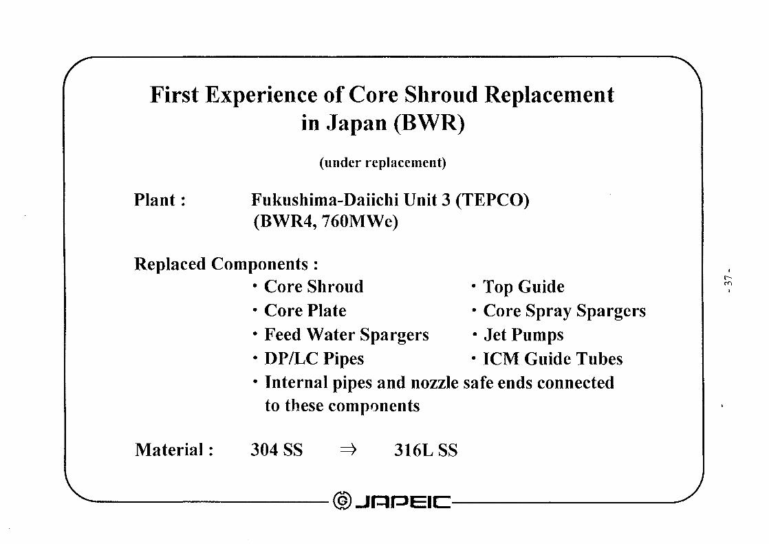


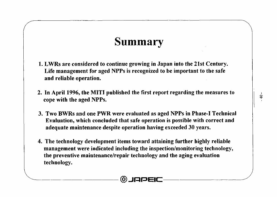


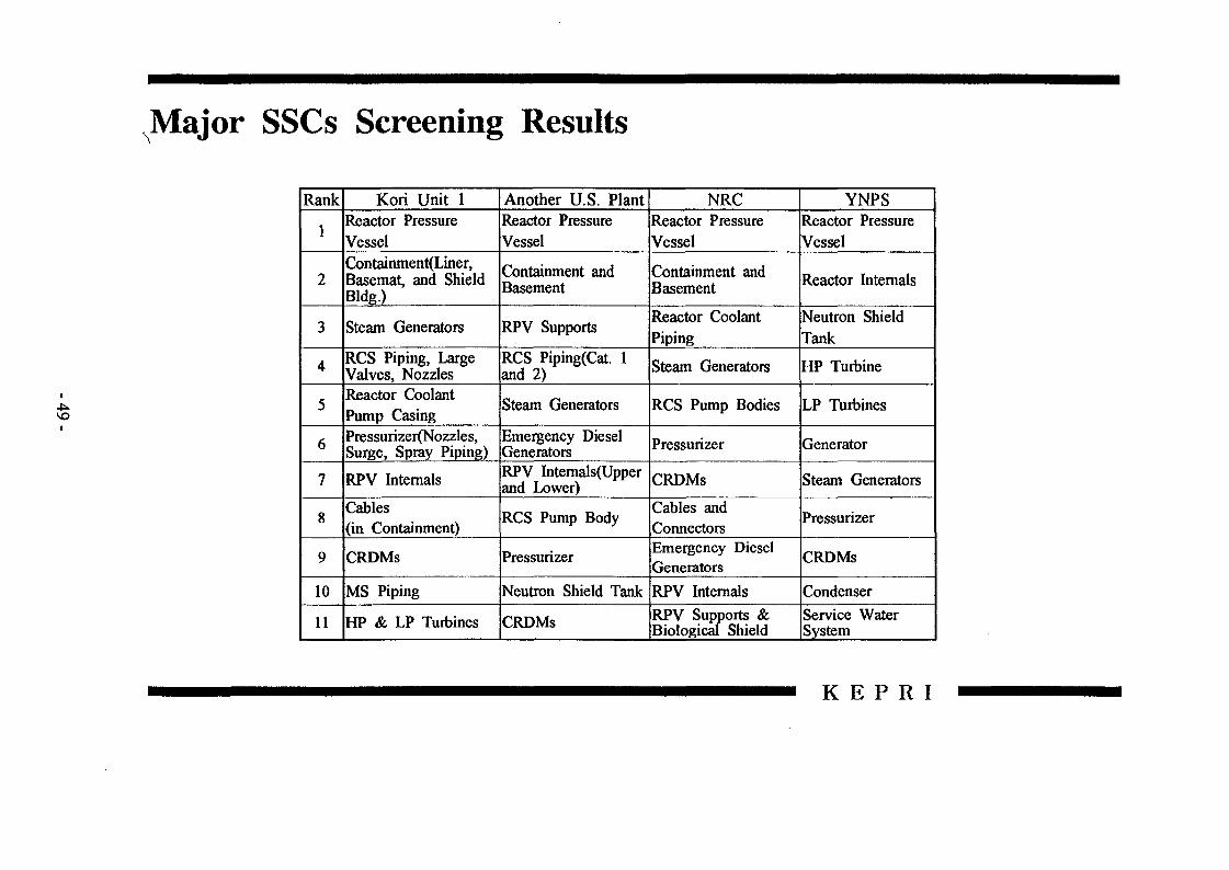


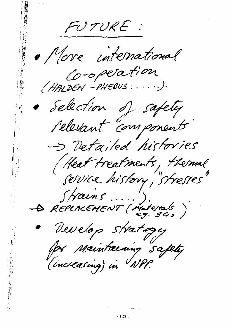


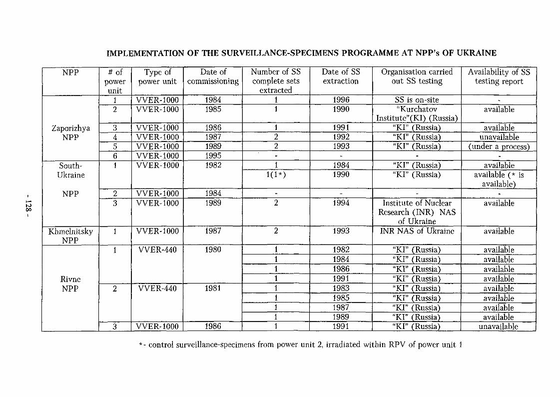


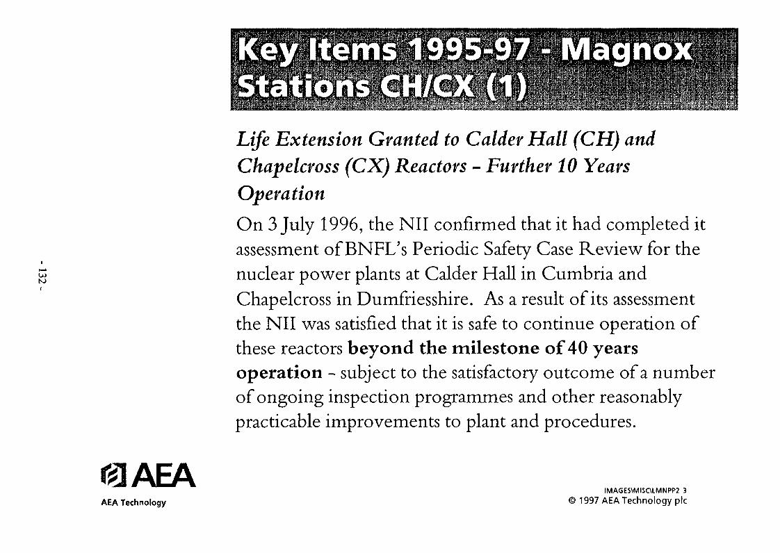


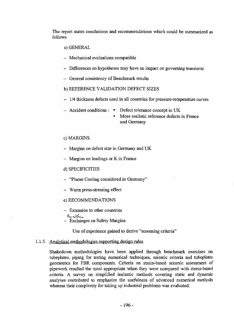


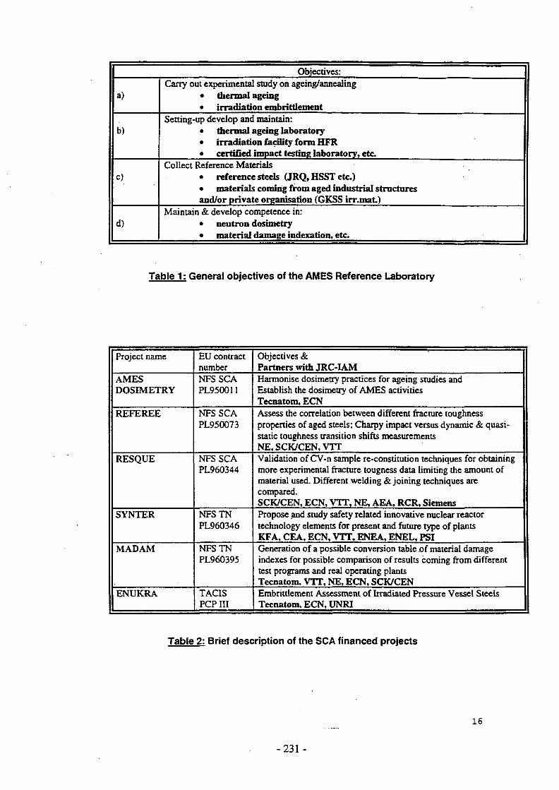


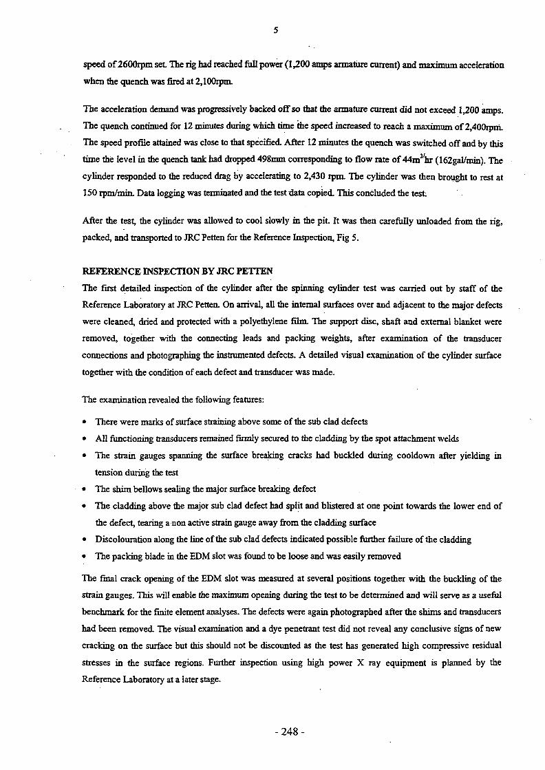


![Developing A [Working] Life Plan](https://static.documents.pub/doc/80x56/545af538af79590b088b5d7d/developing-a-working-life-plan.jpg)


