2 Workflow Technology CLARENCE A. ELLIS University of Colorado ABSTRACT This chapter is concerned with workflow, its systems, its models, its problems and promises. Workflow management systems assist in the specification, modeling, and enact- ment of structured work processes within organizations. These systems are a special type of collaboration technology which we describe as “organizationally aware groupware”. Since the turn of the decade, over 200 new workflow products have been introduced into the world market. This chapter motivates and defines the concepts of workflow. Examples are presented from existing products and prototypes. Finally, we explore some of the current inhibitors and research issues in this fast growing domain. 2.1 OVERVIEW Today, organizations find that there is global competitiveness in many areas, and a continual need to improve productivity. Problems plaguing organizations include increased adminis- trative overhead, external pressures for increased efficiency, internal pressure for increased effectiveness, and desire by workers for more reward and less stress. Many organizations look to technology such as workflow management systems for help. Contemporary organizations typically employ a vast array of computing technology to sup- port their information processing needs. There are many successful computing tools designed as personal information aids (word processors, spreadsheets, etc.) but fewer tools designed for collaborating groups of people. One of the most popular recent types of group/organizational tool is workflow. Workflow management systems are designed to assist groups of people in carrying out work processes, and contain organizational knowledge of where work flows in the default case. This is in contrast to other group tools such as electronic mail or video- conferencing systems which contain no knowledge of work processes, and therefore are not organizationally aware. Workflow is defined as “systems that help organizations to specify, Computer Supported Cooperative Work, Edited by Beaudouin-Lafon c 1999 John Wiley & Sons Ltd
Transcript
2
Workflow TechnologyCLARENCE A. ELLIS
University of Colorado
ABSTRACT
This chapter is concerned with workflow, its systems, its models, its problems andpromises. Workflow management systems assist in the specification, modeling, and enact-ment of structured work processeswithin organizations. These systems are a special type ofcollaboration technology which we describe as “organizationally aware groupware”. Sincethe turn of the decade, over 200 new workflow products have been introduced into theworld market. This chapter motivates and defines the concepts of workflow. Examples arepresented from existing products and prototypes. Finally, we explore some of the currentinhibitors and research issues in this fast growing domain.
2.1 OVERVIEW
Today, organizations find that there is global competitiveness in many areas, and a continualneed to improve productivity. Problems plaguing organizations include increased adminis-trative overhead, external pressures for increased efficiency, internal pressure for increasedeffectiveness, and desire by workers for more reward and less stress. Many organizations lookto technology such as workflow management systems for help.
Contemporary organizations typically employ a vast array of computing technology to sup-port their information processing needs. There are many successful computing tools designedas personal information aids (word processors, spreadsheets, etc.) but fewer tools designed forcollaborating groups of people. One of the most popular recent types of group/organizationaltool is workflow. Workflow management systems are designed to assist groups of people incarrying out work processes, and contain organizational knowledge of where work flows inthe default case. This is in contrast to other group tools such as electronic mail or video-conferencing systems which contain no knowledge of work processes, and therefore are notorganizationally aware. Workflow is defined as “systems that help organizations to specify,
Computer Supported Cooperative Work, Edited by Beaudouin-Lafonc 1999 John Wiley & Sons Ltd
30 ELLIS
execute, monitor, and coordinate the flow of work cases within a distributed office environ-ment” [Bul92]. The system contains two basic components: the first component is the work-flow modeling component, which enables administrators and analysts to define processes (orprocedures) and activities, analyze and simulate them, and assign them to people. This com-ponent is sometimes called the “specification module” or the “build time system”. It also maybe used to view work process statistics, and to make changes to processes.
The second component is the workflow execution (or enactment) component, sometimescalled the “run-time system”. It consists of the execution interface seen by end-users and the“workflow engine”, an execution environment which assists in coordinating and performingthe processes and activities. It enables the units of work to flow from one user’s workstationto another as the steps of a procedure are completed. Some of these steps may be executedin parallel; some executed automatically by the computer system. The execution interfaceis utilized for all manual steps, and typically presents forms on the electronic desktop ofappropriate workers (end-users.) The user fills in electronic forms with the assistance of thecomputer system. Various databases, personal productivity tools, and servers may be accessedin a programmed or ad-hoc fashion during the processing of a work step. Typically, a workflowsystem is implemented as a server machine which has and interprets a representation of thesteps of the procedures and their precedence; along with client workstations, one per end-user, which assists the user in performing process steps. This is typically combined with anetwork and messaging system (or communication mechanism) to allow the server to controlor interact with end-user workstations; also included is a database that stores the processrepresentation, attributes of end-users, and other pertinent workflow information. Many ofthe workflow products are combined with imaging and/or document management systems[Bul92].
2.2 WORKFLOW CONCEPTS AND ARCHITECTURE
This section provides some basic workflow definitions in the context of an example officeprocedure. This is followed by an architectural specification which is typical of current work-flow systems, and is in keeping with our definitions. The terminology generally follows therecommendations of the Workflow Management Coalition which is a non-profit, internationalorganization of workflow vendors, users, and analysts. The coalition, founded in August 1993,has a mission to promote the use of workflow through the establishment of standards for ter-minology, interoperability, and connectivity between workflow products [WMC].
2.2.1 Definition Set
2.2.1.1 Definition (Workflow Management System)
A workflow management system is a system that defines, manages, and executes workflowprocesses through the execution of software whose order of execution is driven by a computerrepresentation of the workflow process logic [WMC].
Many types of office work can be described as connected sets of structured recurring tasks(called workflow processes or procedures) whose basic work steps (called activities) must beperformed by various people (called actors) in a certain sequence. The power of workflowsystems lies in their computerized representation of these processes, and activities. This sec-
WORKFLOW TECHNOLOGY 31
tion describes the basic terminology and capability of workflow; much more power and utilityis possible once this procedural representation is available within the computer system.
A particular workflow application is created by specifying to the workflow system a set ofprocesses and activities which are performed within an organization or workgroup. This isthe first step toward computerized workflow; the goal is to enhance the efficiency and effec-tiveness of the office work, while making the workplace a friendlier, more humane place towork.
2.2.1.2 Definition (Process)
A workflow process (or procedure) is a predefined set of work steps, and partial ordering ofthese steps. A work step consists of a header (identification, precedence, etc.) and body (theactual work to be done).
Examples include the “order processing procedure” within an engineering company, andthe “claims administration process” within an insurance company. Both of these are relativelystandardized and structured, and each can be described by a sequence of steps. Workflow alsoattempts to assist in less structured work tasks. Different steps of a process may be executedby different people or different groups of people. In some cases several steps of a processmay be executed at the same time or in any order. In general, we therefore define a process tobe a partially ordered set of steps rather than a totally ordered set. We also define workflowprocesses in such a way that loops are allowed. Processes typically have attributes, such asname and responsible person, associated with them.
2.2.1.3 Definition (Activity)
An activity is the body of a work step of a process. An activity is either a compound activity,containing another process, or an elementary activity.
An elementary activity is a basic unit of work which must be a sequential set of primi-tive actions executed by a single participant. Alternatively, an elementary activity may be anon-procedural entity (goal node) whose internals we do not model within our structure. Anactivity is a reusable unit of work, so one activity may be the body of several work steps. Forexample, if “order entry” and “credit check” are (sub-)processes, then the activity “send outletter” may be an activity in both of these processes. In this case, these are two distinct steps,but only one activity. An activity instance associated with the body of a particular work stepis called a work step activity.
Activities typically have attributes such as description and mode associated with them. Anactivity has one of three modes. Some work step activities may be automatically executed (au-tomatic mode), some completely manual (manual mode), and some may require the interac-tion of people and computers (mixed mode). For example, if the process is “order equipment”then there may be work steps of:
1. order entry2. credit check3. billing4. shipping.
Order entry in some companies is totally automatic; but credit check is frequently done
32 ELLIS
completely by people (manual mode.) This level of detail of description is typically adequatefor an engineering manager, but is not enough detail for a credit clerk. The credit clerk wouldlike to look inside of the work step called credit check, and see a process that requires stepsof logging each new credit request, gathering data, evaluating a customer, and filling out of areport form. Thus, the body of this step is itself a process with work steps of:
2.1. log request2.2. gather data2.3. evaluate2.4. fill out report form.
Furthermore, the step 2.4 of filling out the report form may itself consist of work steps tofill out the various sections of the form. This example shows that it can be useful to multiplynest processes within processes. Thus, a work step body has been defined to possibly con-tain a process. Work steps typically have attributes, such as unique identifier and executor,associated with them.
By definition, a workflow system contains a computerized representation of the structureof processes and activities. This also implies that there is a means for someone (perhaps asystem administrator) to specify and input descriptions of processes, activities, and orderingsinto the computer. These specifications are called scripts. An ongoing research issue is todevelop better, more end-user compatible scripting languages.
2.2.1.4 Definition (Script)
A script is a specification of a process, an activity, or an automatic part of a manual activity.The composition or building of this script from available building blocks is called scripting.
Once processes and activities have been defined, the workflow system can assist in theexecution of these processes. We separate the concept of the static specification of a process(the template) from its execution.
2.2.1.5 Definition (Work Case)
A work case (or process instance) is the locus of control for a particular execution of a process.In some contexts, the work case is called a job; if a process is considered a Petri net, then awork case is a token flowing through the net. If the process is an object class, then a workcase is an instance. In our example, if two customers submit two orders for equipment, thenthese would represent two different work cases. Each work case is a different execution of theprocess. If both work cases are currently being processed by the order entry department, thenthe state of each work case is the order entry state. Work cases typically have parameters suchas state, initiator, and history associated with them.
Because of the ever changing and sometimes ad-hoc nature of the workplace, it is impor-tant for workflow systems to be flexible, and have capabilities to handle exceptions. Manyprocesses which appear routine and structured are, in reality, highly variable, requiring prob-lem solving and creative exception handling. Another workflow concept that partially helpsaddress these issues is the indirect association of people (called actors) with activities via theconcept of roles. Numerous other advantages accrue by the use of roles.
WORKFLOW TECHNOLOGY 33
2.2.1.6 Definition (Role)
A role is a named designator for a workflow participant, or a grouping of participants whichconveniently acts as the basis for access control and execution control. The execution of ac-tivities is associated with roles rather than end-users. Thus, instead of naming a person asthe executor of an activity, we can specify that it is to be executed by one or more roles. Forexample, instead of specifying that Michael executes the order entry activity, we can specifythat
1. the order entry activity is executed by the order administrator, and2. Michael is the order administrator.
There may be a very large number of activities in which Michael is involved. When Michaelgoes on vacation, it is not necessary to find and change all processes and activities involvingMichael. We simply substitute Michael’s replacement in the role of order administrator bychanging step 2 to
2. Robert is the order administrator.
A role may be associated with a group of actors rather than a single actor. Also, one actormay play many roles within an organization. If there are many order administrators withinour example, then these can be defined as a group, and it is easy to send information to allorder administrators. In this case, an option may be available to “send to all” or alternatively,“send to any” administrator, and the system might use some scheduling algorithm to selectone. Other flexible scheduling algorithms are possible, including the notification of all mem-bers of the group that a job is available, and allowing the first responder to handle the job. Inthis chapter, we use the term participant to refer to a person, a group, or an automated agentas further defined below. For example, the credit check activity in our example is really exe-cuted by the credit department, not by any single person. And the printing operation is reallyexecuted by one of many print servers that might be participants with the role of “printer”.
2.2.1.7 Definition (Participant)
A workflow participant is a person, program, group, or entity that can fulfill roles to execute,to be responsible for, or to be associated in some way with activities and processes. A humanparticipant is called an actor.
Access attributes or capabilities may be associated with participants and with roles. Otherattributes, parameters and structures can be associated as needed. For example, the role ofmanager is perhaps only played by Michael within the order entry department. Thus a param-eter of the role may be the group within which this role applies.
In summary, this section has briefly presented a definition of workflow together with expla-nations of the concepts of process, step, activity, work case, script, role, actor, and participant.These are basic concepts upon which many workflow systems are built. Other concepts (e.g.data repository) will be introduced in this chapter as needed.
2.2.2 Conceptual Architecture
This subsection presents the conceptual architecture of a generic workflow system using theentity-relationship model [Che76]. The architecture builds upon the general concepts intro-
34 ELLIS
Process
Activity
Data Role
ParticipantWork case
N N
M
N
M
N
M M
M
N
1
N
part-of
state-of
responsible-for
player-ofprecedence
used-in
executor-of
M
N
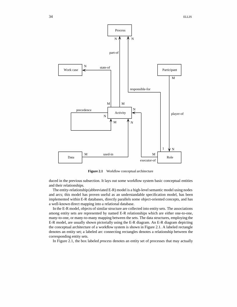
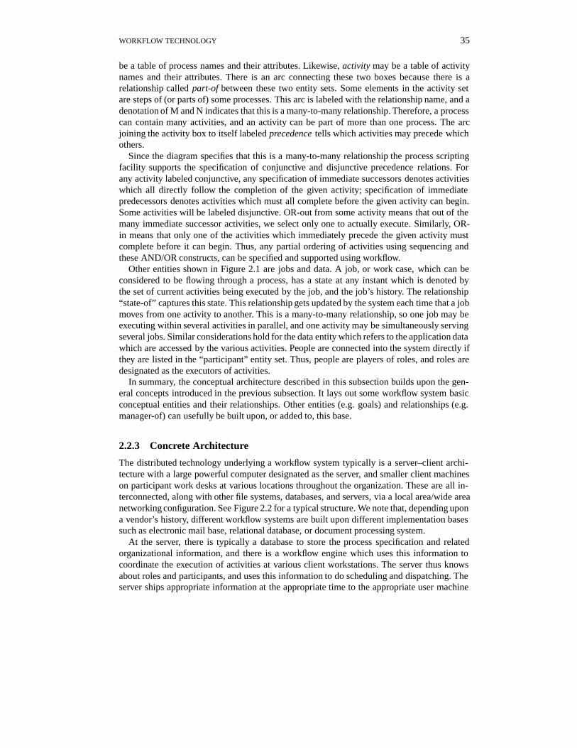
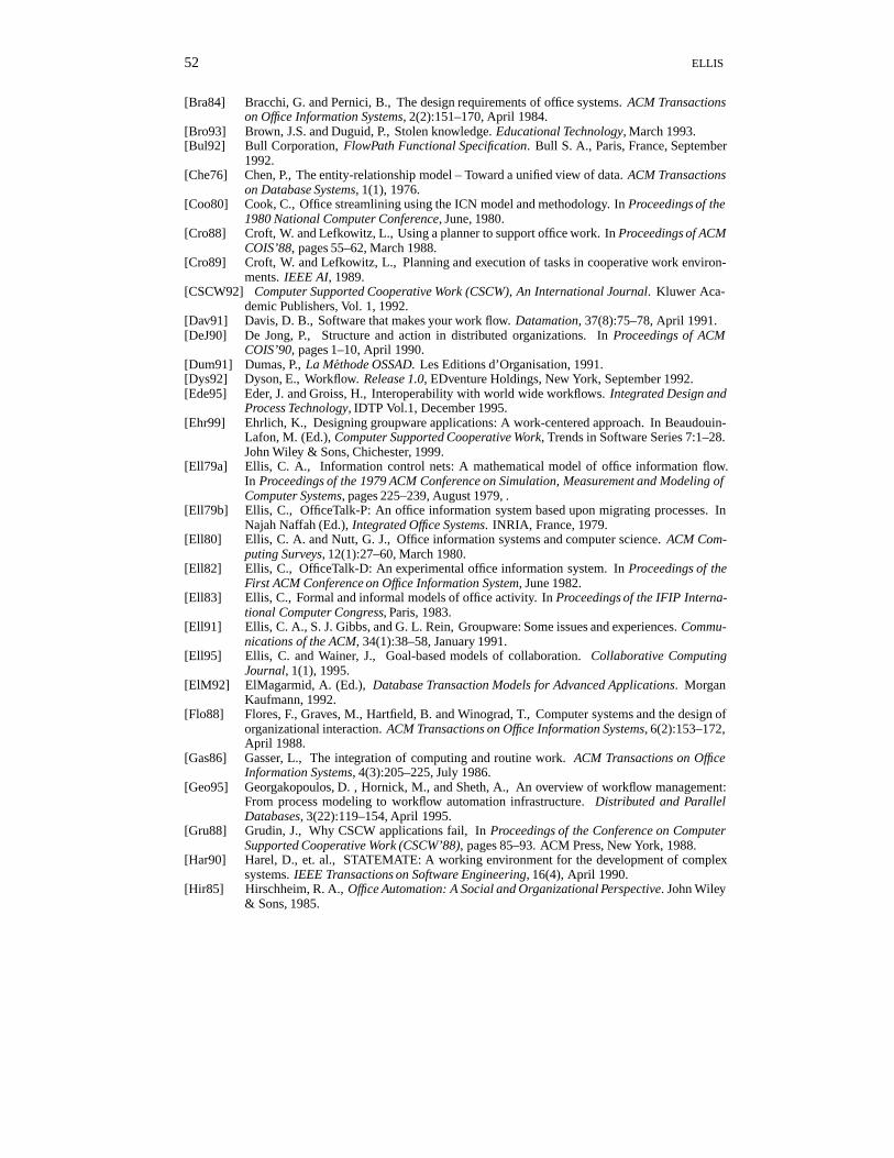
Figure 2.1 Workflow conceptual architecture
duced in the previous subsection. It lays out some workflow system basic conceptual entitiesand their relationships.
The entity-relationship (abbreviated E-R) model is a high-level semantic model using nodesand arcs; this model has proven useful as an understandable specification model, has beenimplemented within E-R databases, directly parallels some object-oriented concepts, and hasa well-known direct mapping into a relational database.
In the E-R model, objects of similar structure are collected into entity sets. The associationsamong entity sets are represented by named E-R relationships which are either one-to-one,many-to-one, or many-to-many mapping between the sets. The data structures, employing theE-R model, are usually shown pictorially using the E-R diagram. An E-R diagram depictingthe conceptual architecture of a workflow system is shown in Figure 2.1. A labeled rectangledenotes an entity set; a labeled arc connecting rectangles denotes a relationship between thecorresponding entity sets.
In Figure 2.1, the box labeled process denotes an entity set of processes that may actually
WORKFLOW TECHNOLOGY 35
be a table of process names and their attributes. Likewise, activity may be a table of activitynames and their attributes. There is an arc connecting these two boxes because there is arelationship called part-of between these two entity sets. Some elements in the activity setare steps of (or parts of) some processes. This arc is labeled with the relationship name, and adenotation of M and N indicates that this is a many-to-many relationship. Therefore, a processcan contain many activities, and an activity can be part of more than one process. The arcjoining the activity box to itself labeled precedence tells which activities may precede whichothers.
Since the diagram specifies that this is a many-to-many relationship the process scriptingfacility supports the specification of conjunctive and disjunctive precedence relations. Forany activity labeled conjunctive, any specification of immediate successors denotes activitieswhich all directly follow the completion of the given activity; specification of immediatepredecessors denotes activities which must all complete before the given activity can begin.Some activities will be labeled disjunctive. OR-out from some activity means that out of themany immediate successor activities, we select only one to actually execute. Similarly, OR-in means that only one of the activities which immediately precede the given activity mustcomplete before it can begin. Thus, any partial ordering of activities using sequencing andthese AND/OR constructs, can be specified and supported using workflow.
Other entities shown in Figure 2.1 are jobs and data. A job, or work case, which can beconsidered to be flowing through a process, has a state at any instant which is denoted bythe set of current activities being executed by the job, and the job’s history. The relationship“state-of” captures this state. This relationship gets updated by the system each time that a jobmoves from one activity to another. This is a many-to-many relationship, so one job may beexecuting within several activities in parallel, and one activity may be simultaneously servingseveral jobs. Similar considerations hold for the data entity which refers to the application datawhich are accessed by the various activities. People are connected into the system directly ifthey are listed in the “participant” entity set. Thus, people are players of roles, and roles aredesignated as the executors of activities.
In summary, the conceptual architecture described in this subsection builds upon the gen-eral concepts introduced in the previous subsection. It lays out some workflow system basicconceptual entities and their relationships. Other entities (e.g. goals) and relationships (e.g.manager-of) can usefully be built upon, or added to, this base.
2.2.3 Concrete Architecture
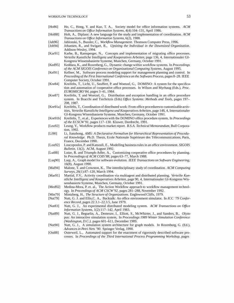
The distributed technology underlying a workflow system typically is a server–client archi-tecture with a large powerful computer designated as the server, and smaller client machineson participant work desks at various locations throughout the organization. These are all in-terconnected, along with other file systems, databases, and servers, via a local area/wide areanetworking configuration. See Figure 2.2 for a typical structure. We note that, depending upona vendor’s history, different workflow systems are built upon different implementation basessuch as electronic mail base, relational database, or document processing system.
At the server, there is typically a database to store the process specification and relatedorganizational information, and there is a workflow engine which uses this information tocoordinate the execution of activities at various client workstations. The server thus knowsabout roles and participants, and uses this information to do scheduling and dispatching. Theserver ships appropriate information at the appropriate time to the appropriate user machine
36 ELLIS
Workflow Server
admin. interface
workflow database
workflow engine
Workflow Client
scripts
executive
user interface
External Server
Communication Base
Workflow Client
scripts
executive
user interface
External Server
Figure 2.2 Workflow concrete architecture
for activity execution. It also implements security and concurrency control, monitors theseexecutions, logs statistics and backup/recovery information, and as necessary sends remindersand time-out information. Occasionally, the server may itself execute an automated activity. Itis also typical for the server to supply an administrative user interface to allow administratorsand analysts to define processes and activities, to gather work performance statistics, to doanalysis and simulation, and to make changes and adjustments to processes.
The client machines are the locus of work activity at enactment time. A client machine typ-ically serves one end-user (secretary, clerk, ...) who we call a participant. Frequently this is anIBM PC class of machine running a Windows operating system, and using a package such asVisual Basic to present a familiar electronic desktop working environment for the end-user.This environment may include local scripts so that some activities can be executed automat-ically or interactively, allowing the local computer to do some of the information processingwork for the user. It should also allow the user to invoke personal productivity tools such aseditors and spreadsheets on a programmed or ad-hoc basis. Finally Internet interconnectivityand access to non-local resources such as a customer database or a mainframe routine, areuseful functions that should be available to the user.
2.3 HISTORICAL PERSPECTIVE AND RELATED WORK
The term workflow was in use at the turn of the century when the industrial revolution wastaking place. There was much efficiency gain, and much profit associated with areas such as
WORKFLOW TECHNOLOGY 37
factory automation [Bae93]. It was also assumed in the mid-1900s that the same techniques(e.g. time and motion studies to optimize office work) would be very successful in bringingautomation to the office. In fact, the history of workflow application in corporate America hasbeen mixed; more systems have silently died than been successful [Bai81, Whi94]. The 1970swere the years of introduction of the first sophisticated Office Information Systems. Some ofthese systems were indeed workflow management systems embedding complex specificationsof the corporation’s office procedures, detailing which procedure steps must precede which,and what data must be used in which steps [Zis77]. The 1970s were a time of wild optimismabout the great beneficial effects upon productivity and effectiveness of this new technology.However, much of this optimism was unfounded. It was observed that organizations succeedonly if people creatively violate, augment, or circumvent the standard office procedures whenappropriate. When these electronic coordinators were introduced into offices, people couldno longer blatantly disobey the office procedures. In many cases, these systems led to inef-fective organizations and technology rejection. Thus, the rigid systems of the 1970s tendedto interfere with work routines rather than expedite them. Workflow was also unsuccessfulin the 1970s because sufficient technology was not available, because personal computers inthe office were not socially accepted, because vendors were unaware of the requirements andpitfalls of group technology, and because networking was not commonly available.
There has been considerable published work which addresses workflow systems. Some ofthe beginnings in this area come from the author’s early work on Officetalk/ICNs in the 1970s[Ell80]. Also, GMD has implemented several versions of Domino [Kre84], a Petri net basedprototype office information system. Usage reports detail numerous problems and reasonsfor user rejection of the system — this typifies problems of current workflow. Other workflowefforts include the Xerox “Collaborative Process Model” [Sar91], Polymer at the University ofMassachusetts [Cro88], Prominand [Kar91], Role Interaction Nets [Rei92], and the WooRKSworkflow prototype within the ITHACA ESPRIT project [Ade92]. There has been a flood ofnew workflow systems in the 1990s, and a flood of papers describing them. See for example,the yearly proceedings of the Workflow 9x vendor conferences.
Considerable effort has been put into workflow studies. Many of these have transpired in theInformation Systems field and the Organizational Design field within business schools. Exam-ples include Bair’s TUMS [Bai82], Woo’s SACT [Woo90], Hirshheim’s model [Hir85], theSociety model [Ho86], Hammer’s BDL and OAM [Sir84], and the OSSAD model [Dum91].Several office models have emerged from concepts of discrete mathematics. These includePetri net based workflow models [Zis77, Hol88, Li90], and graph theory based models[Luq90]. There is also a set of models which have emerged out of the software engineeringcommunity. These could be classified as extended flowchart/state machine notations [Har90],project management models [Kel91], and process programming models [Ost88]. Office mod-els are reviewed and contrasted in several articles including [Ell80], [Bra84], and [Leu92].
An interesting statistic published by the Gartner group, is that in the decade from 1980 to1990, manufacturing productivity in the USA increased 40%, partly due to technology in-vestment, and office productivity declined by 2% despite an estimated one trillion dollars ofoffice automation spending. In the 1980s, there was a swing away from the workflow belief.The thrust of much of this work was to better understand the working of small groups, and toprovide very flexible tools for people to use within unstructured work, and to not attempt tocapture organizational knowledge within the computer system [Ell91]. Some groupware prod-ucts saw success within their limited domains. It was apparent that a huge amount of leveragecould be attained if we could successfully understand groups and organizations enough to
38 ELLIS
produce organizationally aware groupware. It was also apparent that this is not an easy task.One of the lessons learned stems from the social situated nature of office work; this impliesthe need for a user-centered interdisciplinary approach. The 1990s saw the enthusiastic re-birth of interest in workflow; customers have been requesting workflow within all documenthandling and imaging and electronic mail systems. Unfortunately, it seems that many of thebitter lessons experienced in the 1970s and 1980s are still not heeded by many of the greaterthan 200 workflow products on the market today.
As an early example, Officetalk was an experimental office information system developedin the Office Research Group at Xerox PARC in the 1970s [Ell80]. Officetalk was the firstsystem that we know of that provided a visual electronic desktop metaphor across end-users’personal computers. It also provided a set of personal productivity tools for manipulating in-formation, a forms paradigm, and a network environment for sharing information. This familyof systems was created, evolved, and used extensively within the Xerox PARC research lab,and was also tested in selected sites outside of PARC. During the 1970s and 1980s, the authorparticipated in design, evaluation, enhancement, and significant extensions to Officetalk. Thisincluded work on Backtalk [Nut79], an interactive workflow simulator, Officetalk-D [Ell82],a database oriented workflow system, and Officetalk-P [Ell79b], an intelligent forms orientedworkflow system.
However, it sometimes happened that an Officetalk system that was loved and worked won-derfully in the research laboratory, was hated and worked terribly when installed in a typicalproduction office setting. We observed, as others have observed (see Chapter 1 in this book[Ehr99]), that workflow systems are people systems, and must take into account the situated,frequently unstructured nature of office work. Many workflow systems have failed becausethey did not adequately take into account the social and organizational setting into which theywere being placed.
2.4 WORKFLOW MODELS AND MODELING
Models of workflow have spanned the gamut from very informal to very formal. Informalmodeling has been reported by Suchman [Suc83]. Early work to formalize workflow modelswas presented in the thesis of Michael Zisman [Zis77] where he developed APNs (AugmentedPetri Nets) that attached production rules to specify semantics within Petri nets. These con-cepts were implemented in the SCOOP system. The model UBIK represents an organizationby “configurators” which perform actions by sending messages to each other [DeJ90]. TheOFS model represents the flow of forms within an office; within this model, all messages,documents, letters, etc., are defined to be forms [Tsi82]. Another alternative is to model theoffice as a database with transactions. TEMPORA is an integrated architecture for doing busi-ness design and analysis within a database environment [Lou92]. This is a small sampling ofthe large number of models which have been used for the modeling of offices and workflow.
Our research group at the University of Colorado is (and has been for many years) activelyresearching the Information Control Net model (abbreviated ICN) for information systemsanalysis, simulation, and implementation. The ICN is a simple, but mathematically rigorousformalism created and designed in the 1970s specifically to model office procedures [Ell79a].ICNs are actually a family of models which have evolved to incorporate control flow, dataflow, goals, actors, roles, information repositories, and other resources [Ell83]. ICNs havebeen studied in universities [Dum91] and applied in industry [Bul92]. They have been shown
WORKFLOW TECHNOLOGY 39
to be valuable for capturing office procedures, for mathematical analysis, for simulation, andfor systems implementation. Some of the documented analyses of ICNs include through-put, maximal parallelism, reorganization, and streamlining [Coo80]. As a comprehensible,generic, and extensible process model, the basic ICN is described next.
2.4.1 Mathematical Definition
The ICN family of models are structured around the fundamental observation that organiza-tions encompass goals, resources, and constraints. Some organizations are very highly struc-tured, with precisely defined processes and rules; others are very loosely constructed withpredominantly unstructured activities. Owing to the variety of organizations, and owing tothe variety of questions that models may be employed to investigate, we have seen that noone model adequately addresses all aspects. Thus, we derive a family of models by selectingdifferent types of resources and different levels of structure to incorporate in any particularmember of the family. For example, an organizational model which focuses upon informalinterpersonal communication must incorporate the very important resource of people, and theroles that they play in the organization. For the thrust of this chapter, we use the basic “controlICN” which models partial orderings of activities and their control structures; this explanationdoes not include the data structure component.
Definition: A Marked Control ICN is a marked graph specified as a 4-tuple, G =(C; r; l;m) where
(1) C is a finite set of nodes, fc1; c2; :::; cng.(2) r is a relation over C � C which defines edges of the graph G. If (c1; c2) is a member
of r, then there is an edge from c1 to c2. We say that the edge is an output of c1, and an inputof c2.
(3) l is a function from C into f0; 1g denoting the input–output logic of nodes. l(c i) = 0denotes conjunctive logic and l(ci) = 1 denotes disjunctive logic. By convention, we separateactivity nodes (single-input, single-output) from AND nodes (conjunctive input and output)from OR nodes (disjunctive input and output).
(4) m is a marking for the graph G which associates a set (of tokens) with each node andeach edge of G. If x is a member of C [ r, then m associates with x a set M (x) such that ifM (x) is nonempty, then x is said to be marked. The elements of M (x) are the tokens residingon the graph component x. A token is a marker that may cause a node to fire. If a graphcomponent x contains a token t, then we say the component x is marked with the token t.
We are now in a position to describe how a marked ICN executes:A node, ci, with l(ci) = 1 is pseudo-enabled if there is at least one input edge, r(cj ; ci)
such that M (r(cj; ci)) is not empty (OR logic). A node, ci, with l(ci) = 0 is pseudo-enabledif M (r(cj; ci)) is not empty (AND logic) for every input edge of ci, r(cj; ci).
A node ci can fire if it is pseudo-enabled; initiation of firing results in a change of markingsuch that if l(ci) = 1, then some token t in M (r(cj ; ci)) is deleted from one M (r(cj; ci)),and added to M (ci). If l(ci) = 0, then some token is deleted from each M (r(cj; ci)), and asingle token is added to M (ci).
When a node terminates an execution at some finite time after its initiation of firing, thensome t in M (ci) is deleted from M (ci). If l(ci) = 1, then t is added to M (r(ci; cj)) for somesuccessor node cj; if l(ci) = 0, then t is added to M (r(ci; cj)) for all successor nodes cj.
40 ELLIS
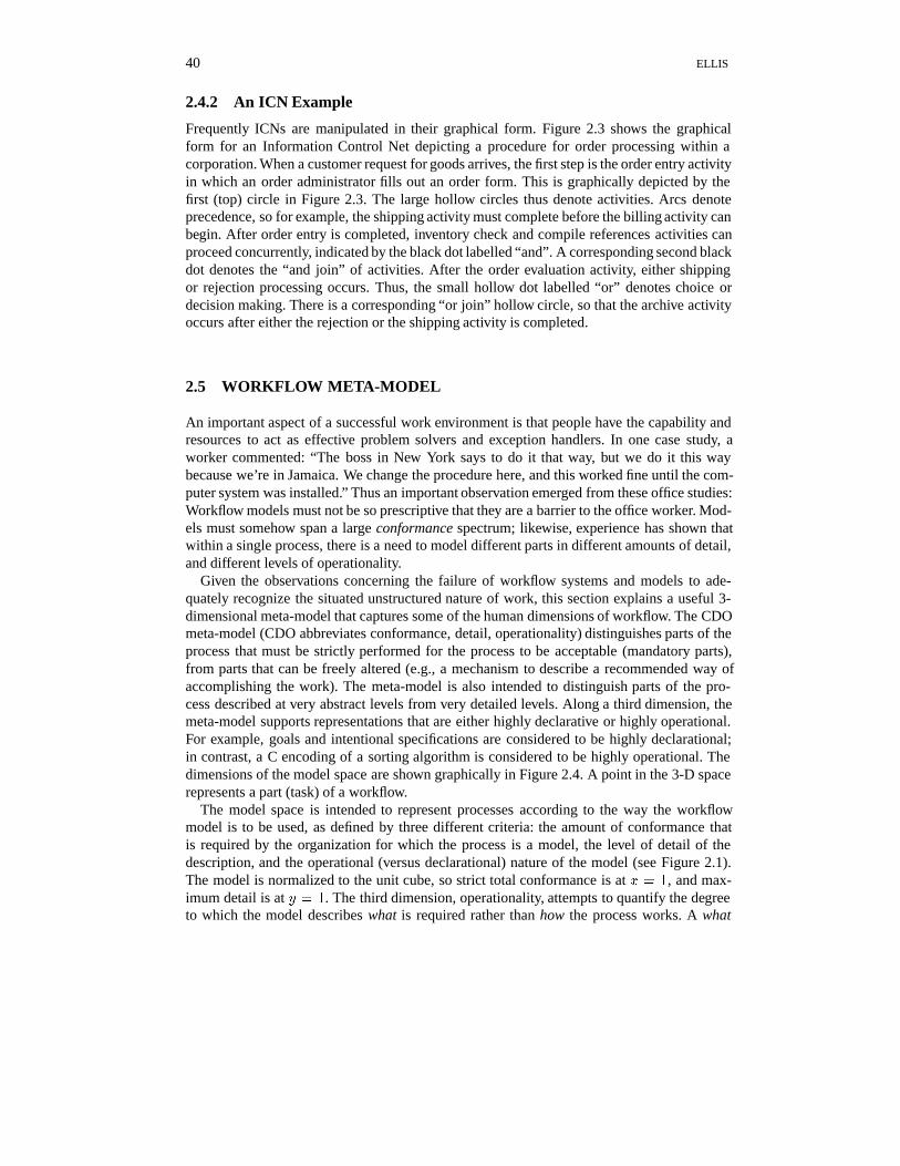
2.4.2 An ICN Example
Frequently ICNs are manipulated in their graphical form. Figure 2.3 shows the graphicalform for an Information Control Net depicting a procedure for order processing within acorporation. When a customer request for goods arrives, the first step is the order entry activityin which an order administrator fills out an order form. This is graphically depicted by thefirst (top) circle in Figure 2.3. The large hollow circles thus denote activities. Arcs denoteprecedence, so for example, the shipping activity must complete before the billing activity canbegin. After order entry is completed, inventory check and compile references activities canproceed concurrently, indicated by the black dot labelled “and”. A corresponding second blackdot denotes the “and join” of activities. After the order evaluation activity, either shippingor rejection processing occurs. Thus, the small hollow dot labelled “or” denotes choice ordecision making. There is a corresponding “or join” hollow circle, so that the archive activityoccurs after either the rejection or the shipping activity is completed.
2.5 WORKFLOW META-MODEL
An important aspect of a successful work environment is that people have the capability andresources to act as effective problem solvers and exception handlers. In one case study, aworker commented: “The boss in New York says to do it that way, but we do it this waybecause we’re in Jamaica. We change the procedure here, and this worked fine until the com-puter system was installed.” Thus an important observation emerged from these office studies:Workflow models must not be so prescriptive that they are a barrier to the office worker. Mod-els must somehow span a large conformance spectrum; likewise, experience has shown thatwithin a single process, there is a need to model different parts in different amounts of detail,and different levels of operationality.
Given the observations concerning the failure of workflow systems and models to ade-quately recognize the situated unstructured nature of work, this section explains a useful 3-dimensional meta-model that captures some of the human dimensions of workflow. The CDOmeta-model (CDO abbreviates conformance, detail, operationality) distinguishes parts of theprocess that must be strictly performed for the process to be acceptable (mandatory parts),from parts that can be freely altered (e.g., a mechanism to describe a recommended way ofaccomplishing the work). The meta-model is also intended to distinguish parts of the pro-cess described at very abstract levels from very detailed levels. Along a third dimension, themeta-model supports representations that are either highly declarative or highly operational.For example, goals and intentional specifications are considered to be highly declarational;in contrast, a C encoding of a sorting algorithm is considered to be highly operational. Thedimensions of the model space are shown graphically in Figure 2.4. A point in the 3-D spacerepresents a part (task) of a workflow.
The model space is intended to represent processes according to the way the workflowmodel is to be used, as defined by three different criteria: the amount of conformance thatis required by the organization for which the process is a model, the level of detail of thedescription, and the operational (versus declarational) nature of the model (see Figure 2.1).The model is normalized to the unit cube, so strict total conformance is at x = 1, and max-imum detail is at y = 1. The third dimension, operationality, attempts to quantify the degreeto which the model describes what is required rather than how the process works. A what
WORKFLOW TECHNOLOGY 41
Order Entry
Inventory Check CompileReferences
EvaluateReferences
no
yes
Order Evaluation
Rejection Processing Shipping
Billing
Archive
and
orreject accept
Figure 2.3 Information Control Net for order processing
42 ELLIS
Detail (y)
Conformance (x)
Operationality (z)
Figure 2.4 CDO model dimensions
model is highly declarative (near z = 0); a how model is highly operational (near z = 1). Inthis domain space, systems that represent only structured work, fully specified, codified, andrequired, are at x = 1, y = 1, and z = 1; this is the typical workflow point in the space.Workflow models and systems frequently do not provide assistance below this point. On theother hand, groupware systems intended to address unstructured work are in a space closer tox = 0, y = 0, and z = 0. Fully automated workflow enactment systems could be (ideally)characterized as a point in the space with x near to 1, y near to 1, and z = 1. Systems thatfocus on exception handling are in a space where x << 1. Goal-based systems typically op-erate in a domain in which z is near to 0, but x and y vary according to the specifics of themodel.
The extended ICN model, used in some of our recent studies, is intended to address the fullspace, with different parts of the model addressing different subspaces according to the needfor that part of the model. For example, if part of the work is highly structured, operationallyspecified, and required to be accomplished according to the specification, then it should bemodeled differently from work for which only the goal is known. The model should allow oneto represent a process for which parts are operational and required, while the way that otherparts are executed is arbitrary, provided that the executions satisfy the intent. The extendedICN model allows different parts (or sub-tasks) of a process to be modeled at different pointsin the 3-D space; all within the same ICN model.
One aspect of an ICN specifies activities (or tasks, or process steps) and their attributes inthe process; each activity belongs to a region whose type is (informally) defined by a point orregion in the space in Figure 2.1. For example, a type “R” (for required work) region might berepresented by a point in the (1; y; z) plane; the model can be represented as a conventionalICN subgraph composed entirely of required (mandatory) steps.
A type “A” region (for assisted work) may use an operational or declarational style speci-fication, but the submodel in the region can be interpreted as one approach to accomplishingthe work. This type of specification is a point in the (0; y; z) plane; it is used when a processdesigner has one notion of how to accomplish the work, but realizes that different situationsrequire different variations on the specification. The A-region work can be used directly, orit can be used to (manually) infer the intent of this part of the work. This is typically a muchhealthier way to view a workflow specification than to consider it the immutable total specifi-cation that must be followed exactly.
A type “D” region (for declaration region) represents a part of the model that defines whatthe region is intended to accomplish, rather than a description of how the work must/might be
WORKFLOW TECHNOLOGY 43
conducted. This type of region occurs at points such as (0; 1; 0) and (:5; :5; 0). Thus, points inthe (x; y; 0) plane are “non-operational” specifications.
Ongoing research work at the University of Colorado focuses on exploring new models toexplicitly distinguish among policy, process, and regulations in different regions of our 3-Dspace. The dimensions of this model are not totally orthogonal, and they obviously do nottotally span the space of all human dimensions. Note, for example, that a workflow processdescription which has a very high degree of detail is also likely to have a high degree ofoperationality, so these dimensions seem to be not totally independent in general. There are,however, cases in which process descriptions are detailed, but not operational. This occurs inrule-based systems which have huge numbers of rules (constraints), but are not operationalbecause the rules are not adequate to completely specify the process.
Indeed, some researchers assert that in numerous human situations, there is no such thingas a “complete and explicit” account of the process because all process instances are situatedand implicit [Suc87]. Indeed, Brown points out [Bro93] that abstraction from process instanceto process class (i.e. modeling) is itself an imperfect situated social practice that is developedin the social context of an ongoing meta-process. An example is learning to ride a bicycle —books give tips, but not an algorithm. You cannot simply learn from a book.
In the case of driving an automobile, some of the “official rules of the road” books are quitethick manuals articulating auto driving distances and courtesies and places not to park and soforth. Many of these books list more “don’t do” constraints than “do” steps. These manualscontain enormous detail, but they do not give you an algorithm for driving. Thus they do not,and are not intended to be, operational.
Conversely, there exist many process descriptions that are operational, but not detailed. Thestatement within an order processing process: “All orders must be routed to credit check, thenbilling, then shipping” is operational but not detailed. It is operational because a workflowsystem can automatically coordinate the electronic forwarding of the order forms to the correctdepartments from these specifications. However, the above statement is not detailed — itgives us no information about what is supposed to happen inside of credit check or billing orshipping.
Although the CDO meta-model does not span the space of all human dimensions, and itsdimensions are not totally orthogonal, the model nevertheless is quite useful to present a novelprocess analysis perspective, and to illustrate gaps in the space of previous models. We believethat this new perspective might be particularly useful in understanding the role that variousmodels should play in large enterprise re-engineering efforts.
2.6 EXAMPLE SYSTEMS
2.6.1 IBM FlowMark
The IBM workflow management product is FlowMark, a system which was beta-tested in1993, and first released as a product in 1994. FlowMark clearly distinguishes workflow build-time (modeling and analysis) from run-time (enactment). The run-time system is useful whenactors (end-users of the system) at their workstations are doing the process work steps (ac-tivities) that have previously been specified. Run-time functions coordinate and oversee theexecution of activities within the distributed system, while maintaining backups, and audittrails. Run-time allows those participants with proper access rights to start and terminate pro-
44 ELLIS
cesses and activities, to view their up-to-date to-do lists, and to access application data asneeded.
The build-time system is useful for creating and changing the specification of processes.Build-time functions include facilities to allow the drawing, editing, and compilation of pro-cess graphs. The creator or analysts during build-time can create, test, simulate, and animateprocess specifications, can assign staff to activities, and can associate programs (scripts) withactivities. The diagrammatic process graphs allow one to create and manipulate activity icons,data icons, and connector arcs. Criteria for control flow branching and decision making arespecified via conditions attached to arcs. Data flow is specified via containers, data structures,and data arcs. Aggregates of activities called blocks and bundles allow diagrams to remainsmall and comprehensible via activity nesting. Properties associated with activities includeactors, I/O data, scripts, who is responsible, time, manual/automatic switch, starting condi-tions, and completion conditions.
The FlowMark organizational model is interesting. Notions of roles and actors are capturedwithin the staff specifications, and relationships. The staff specification can include partici-pants (end-users), levels, roles, organizations and relationships. People have attributes suchas userID, absent flag, and level. Levels are integers between 0 and 9 inclusive which can belocally interpreted by different applications. For example one company may decide that 0 de-notes novice, 1 through 3 is associate, and above 3 denotes expert. Organizations are definedas groups with managers, and they are related by a tree structure. Each participant is involvedin two types of relationships. They can be the player of multiple roles, and they belong toexactly one organization.
The above concepts and definitions are stored in a FlowMark database after they are created.For distribution and interoperability, FlowMark definitions can be described in an ASCII textfile in an external format called FlowMark definition language (FDL). The FlowMark work-flow management system provides import and export utilities so that process graphs and otherspecifications can be ported from one location to another via FDL.
2.6.2 Action Workflow
The Action Workflow product by Action Technologies Inc., provides a workflow model, andarchitecture based upon the philosophical notions of Heidegger, and the linguistic speech acttheory. These notions and theory are well explained in publications by Winograd and Flores[Flo88, Med92], who are the founders of the company. The creation of this framework basedupon a multi-disciplinary theory is unique and potent. Winograd and Flores point out thatall interactions (or conversations) are composed of communication acts which must be inter-preted, and that are subject to mis-interpretation by the receiver. Speech act theory suggeststhat there are a finite number of categories of speech that characterize all communications.Computer systems can help to avoid mis-interpreted communications by clearly displayingthe category of each communication to the receiver.
The theory can be applied to workflow by considering each work case as a conversationbetween a “customer” who wants the task to be done, and a “performer” who takes on en-actment of the task or process. In Figure 2.1 we saw an example where someone wants tobuy goods — this person is the customer to whom the goods (and the bill) will be delivered.The performer in this case is the company that will supply the goods to the customer. Everyworkflow, under this model, is drawn as a loop with four phases:
WORKFLOW TECHNOLOGY 45
1. the customer formulates the request2. the customer and performer negotiate the terms of agreement3. the performer does the task4. the performer and customer negotiate the customer satisfaction.
The analysts at Action Technologies provide a convincing argument that the negotiationphases are very important, but that all too often the fourth phase (customer satisfaction) isignored. In their product usage, no phase is ignored because a loop is not closed (completed)until all four steps have been completed, implying that the customer has said “I am satisfied.”Of course, loops most often have sub-loops nested within the different phases, allowing del-egation, subcontracting, or simply the specification of various levels of detail. Frequently theperformer of a loop becomes the client of a sub-loop.
Action Technologies also has a client–server architecture which can execute on severaldifferent platforms. Like the FlowMark system, there exists an intermediate workflow spec-ification language and a workflow language interpreter that enables compilation to/from thegraphical nested loops diagram. The speech act theory has been the basis of other productsalso, and the source of much lively debate in the research community.
2.6.3 Polymer
Polymer is an experimental goal-based workflow system constructed at the University of Mas-sachusetts [Cro88]. As Professor Bruce Croft, leader of the Polymer project explained: “Poly-mer is intended to assist in tasks that are loosely structured, multi-agent, under-specified, andcomplex.” The potential utility of this approach can be understood by noticing statements thathave been made concerning human work behavior: “People do not follow every step of a workprocedure specification; rather they know the goal of their task and do whatever is necessaryto attain that goal.” Doing this invokes the creative and unstructured activities that help an or-ganization to flourish. Many organizations have voluminous procedures manuals, but almostno employee sits down and reads these in all of their detail.
It is well known that many successful managers work in this mode. It is also the casethat many office tasks that seem very structured and simple, frequently have unstructuredproblem solving tasks imbedded. Consider the difficult sub-task done by the order entry clerkof interpreting the signature of a customer on a piece of paper. At times this can be quite achallenge. Thus, instead of building an over-structured workflow system that forces the usersinto unnatural, inefficient and ineffective step-by-step processing, a workflow system mightallow workers to work via goals. Furthermore, the work of Croft and team attempts to createa workflow system that knows the goals and works with the humans to help achieve them.
Polymer uses concepts and technologies from the artificial intelligence literature to do goal-based planning [Cro89]. It attempts to satisfy the goals that are specified in a top-down depthfirst traversal fashion. Polymer allows the specification of tasks, agents, objects, goals, andplans. Within an activity description, there can be goals, preconditions, postconditions, andalso subgoals. Besides this application description module, there is also a planner, an ex-ecution monitor, a truth maintenance module, and user interaction module. Other researchprojects are also investigating goal based approaches to workflow [Ell95]. This is an areaof great promise which is still in the research phase. The next section discusses workflowresearch directions further.
46 ELLIS
2.7 RESEARCH DIRECTIONS AND ISSUES
Workflow systems have been categorized into a) administrative workflow systems, b) produc-tion workflow systems, and c) ad-hoc workflow systems. An administrative system typicallyhas complex administrative types of processes to administer. There may be many diverse andcomplex sub-processes, and a lot of dependency is placed on the system to monitor and re-mind people. Examples include billing and order processing. Some research issues prominentwithin the administrative category include integration, interoperability, and efficient triggeringmechanisms. In contrast, a production workflow is very structured, and high volume. Thus,many parts of this can be and are relatively highly automated, and the number of work casesper unit time is high. For example, customer inquiry processing within a large telephone com-pany has millions of diverse inquiries per month [Dav91]. Many of the tasks and processsteps are done wholly by computer, and a good transaction management system is an impor-tant part of this. Research issues of efficient extended transaction mechanisms, concurrencycontrol, recovery, and distributed architecture are important within this category. Finally, thead-hoc workflow is one in which there is much unstructured work, and in which much of theplanning of which steps to take cannot be done in advance. Much of the work of managershas been described [Min79] as “fire fighting and crisis management”, and is very unplannedin its detail. Ad-hoc workflow is frequently a relatively small workflow in terms of the numberof transactions incoming, and in terms of the complexity of the mainline people and processspecifications. There is need for people to be creatively involved, and for group problem solv-ing to be supported. An example in this category is document routing which is dependent uponthe content of the document, and human judgement about who in the organization it shouldbe routed to next. Given these distinct workflow types one might suspect that their problemsare disjoint. This is not the case. Note that these categories are actually all present in manyworkflow situations. Areas in which very similar problems arise include exception handlingand dynamic organizational change. These two exemplary research challenges, and others, areexamined next in this section.
2.7.1 Exception Handling
One attribute which distinguishes workflow systems from many other kinds of computer sys-tems is people. Typically workflow involves people in non-trivial ways. People are not simplythe consumers of output, but are intimately involved in the processing. Several studies of of-fices have been done with an express interest in observing and categorizing the exceptionprocessing. These studies have found that there is a large amount of exception handling inall three of the categories of workflow. And the creativity and problem solving abilities ofhumans, rather than just computers, are strongly needed. Thus, successful workflow designsneed to think beyond the computer as a tool to automate and replace people, to computeras collaborator and communication vehicle to help people in problem solving and exceptionhandling.
In a recent Ph.D. dissertation by Heikki Saastamoinen [Saa95], he analyzed exceptions byperforming an 8 month study at a large paper handling company in Finland. He looked at thefrequency of exceptions, their scope, complexity, type, amount of delay, and amount of repairwork. He found that exceptions are consuming a huge amount of the time of the people inorganizations. These findings are consistent with other studies, and statistical analysis usinga large number of questionnaires to a sampling of companies [Saa94, Str89] that have been
WORKFLOW TECHNOLOGY 47
published. Saastamoinen finds that it is useful to separate exception detection from exceptionhandling from exception prevention. He also notes that some people use the term “error” forexception, and that this is sometimes inappropriate because it is frequently not a mistake, buta “freak occurrence of nature” that is a fault. He interestingly also found several examples of“positive exceptions” which helped raise awareness of people, and led to a better organization.He classified exceptions into three types:
1. Established Exceptions: they are not the normal case, but there are rules to handle them;they are anticipated.
2. Otherwise Exceptions: no rule to handle, but these are local bounded exceptions wherescope and goal are known.
In established exceptions, techniques like UNDO, REDO, compensation and rollback mayapply from database theory. An example of this type of exception is “external tax paid forinternal order”. There is a standard compensation process which compensates for this, andthis exception was anticipated by the system designers. The important point that was madeconvincingly by Lucy Suchman, is that it is impossible for the system designers to a priorithink of all exceptions [Suc87]. So, for example in a trip planning system, the designers mayimplement an exception handler for the case of “airplane full” (an established exception), butmay not have implemented any exception handler for “airplane crashes” (a true exception).Saastamoinen found that the exception detection, prevention, and handling take up more than50% of the work time in many companies. He found that true exceptions were the most expen-sive in terms of delay, complexity, and usage of the most time of the most expensive peoplewithin an organization. The older workflow systems were especially bad offenders. First theywould regularly insult the users by printing a message for each exception that was worded tomake it seem like an “error!”. These systems were so rigid that they did not allow humansto do reasonable work-arounds. And they frequently hindered rather than helped the creativepeople to solve problems.
Thus, an important issue is the question of how workflow systems can be designed forunexpected exceptions, to help rather than hinder the knowledge workers. The work fold-ers concept of Karbe tried to provide exception handling facilities for the top ten exceptions[Kar91], but found that this was inadequate for true exceptions. The FlowPath workflow prod-uct introduced the capability for any user at any time to send a work case to another activity,role, or participant with parameters to specify further routing, time of delivery, return to senderafterwards, etc. A problem of access control and general control of the process then emerges.Lucy Suchman gives an excellent example of a true exception within an accounting office inwhich somehow one page of a two page billing statement is missing [Suc83]. It takes quitea lot of creativity and problem solving to crack this one, and to stay within the rules of theorganization.
2.7.2 Interoperability
One of the complaints that is very high on the list for workflow customers is that their work-flow systems cannot adequately interact with their legacy data processing systems. Frequentlysome inputs, outputs, and intermediate results of the workflow system must go to and fromother previously existing computer systems. The workflow typically needs to interact with
48 ELLIS
a number of other databases, file systems, and applications. In many organizations it is notfeasible to throw away the large mainframe systems simply because there is a new workflowsystem in house. Thus, pragmatically speaking, a strong requirement of workflow manage-ment systems is to communicate and interact well with a variety of other data processing andinformation systems within an organization. Owing to the proliferation of different types andstyles of these systems, workflow vendors face a significant challenge. Vendors must seek so-lutions that offer quick, low effort programming of varied interfaces to varied legacy systems.This requirement also extends to interaction with varied applications, databases, and personalproductivity tools.
Another type of interoperability that is becoming more and more in demand is interoper-ability between different workflow systems.The workflow management coalition is trying toaddress this and other interfacing problems within their standards work [WMC]. For example,if a large corporation is buying expensive goods, they may use their workflow managementsystem to execute the equipment purchase process. Preferably, their purchase orders and otherrelevant workflow outputs can be automatically and electronically input to the workflow sys-tem of the supplier. The work of Eder and group [Ede95] explores issues of workflow on theInternet; inter-organizational interoperability can be obtained by using the extended HTTPand HTML protocols, and EDI. There are now a number of workflow systems whose trans-port medium is strictly the Internet technology [W4].
2.7.3 Dynamic Change
Change is a way of life in most organizational and personal settings. There are many differenttypes of change, scales of change, and timeframes for change. Workflow systems must supportrather than hinder this changeability. Those organizations in the modern business world whichrefuse to change are typically headed toward rapid obsolescence because they cannot compete.Organizations must frequently make structural changes such as:
� adding a new employee� adjusting procedures for a new tax law� filling in for a manager on vacation.
There are also important issues concerned with change of application data, evolution oforganizational objectives, change of social communication structures, etc. In order to makestructural changes as above within a workflow system context, it is typically and unfortu-nately necessary to suspend or abort the work in progress within the execution module, andstart up the specification module to make the changes to the specification. Then after thechange, the specification module is terminated, parameters are re-initialized, the specifica-tion is re-compiled, and once again, the execution module is started. This is an inefficient,error prone, and ineffective process because many organizations find it very unproductive,and sometimes impossible, to shut down all activity in order to make changes. From phar-maceutical factories to software engineering houses, this is a nagging problem — the biggerthe organization, the more complex are the processes, and the more painful the change pro-cess. Today, organizations usually do not solve this problem, they cope, evade, or “muddlethrough”.
By combining the first and second components of workflow, the model is constantly avail-able and process change can potentially occur dynamically if the correctness and consistencyproblems of dynamic change can be solved. Thus, even with these components combined,
WORKFLOW TECHNOLOGY 49
we do not know how to smoothly and correctly handle the myriad of changes which areconstantly happening. Although there is considerable literature addressing workflow, officemodeling, and business re-engineering, the problem of dynamic structural change has notbeen generally solved. In this section, we see an example of one type of incorrect behaviorthat can accidentally occur within dynamic structural change. The conclusion is that in largeorganizations around the world, dynamic change is an ad-hoc and risky event.
Change to the values of application data items is a normal type of activity that occursin administrative information processing. However, structural change to the procedures andprocesses is not considered “normal” by most organizations. Dynamic means that the changeto the process occurs while the process is executing. Static change, in the ICN context, meansthat the execution of the process is halted, all tokens are removed, and the change is applied atquiescence. Static correctness means that certain assertions or constraints are not violated —it implies that we have a set of correctness criteria that hold for all tokens flowing through theICN before the change, and also for all tokens that enter the ICN after the change is completed.
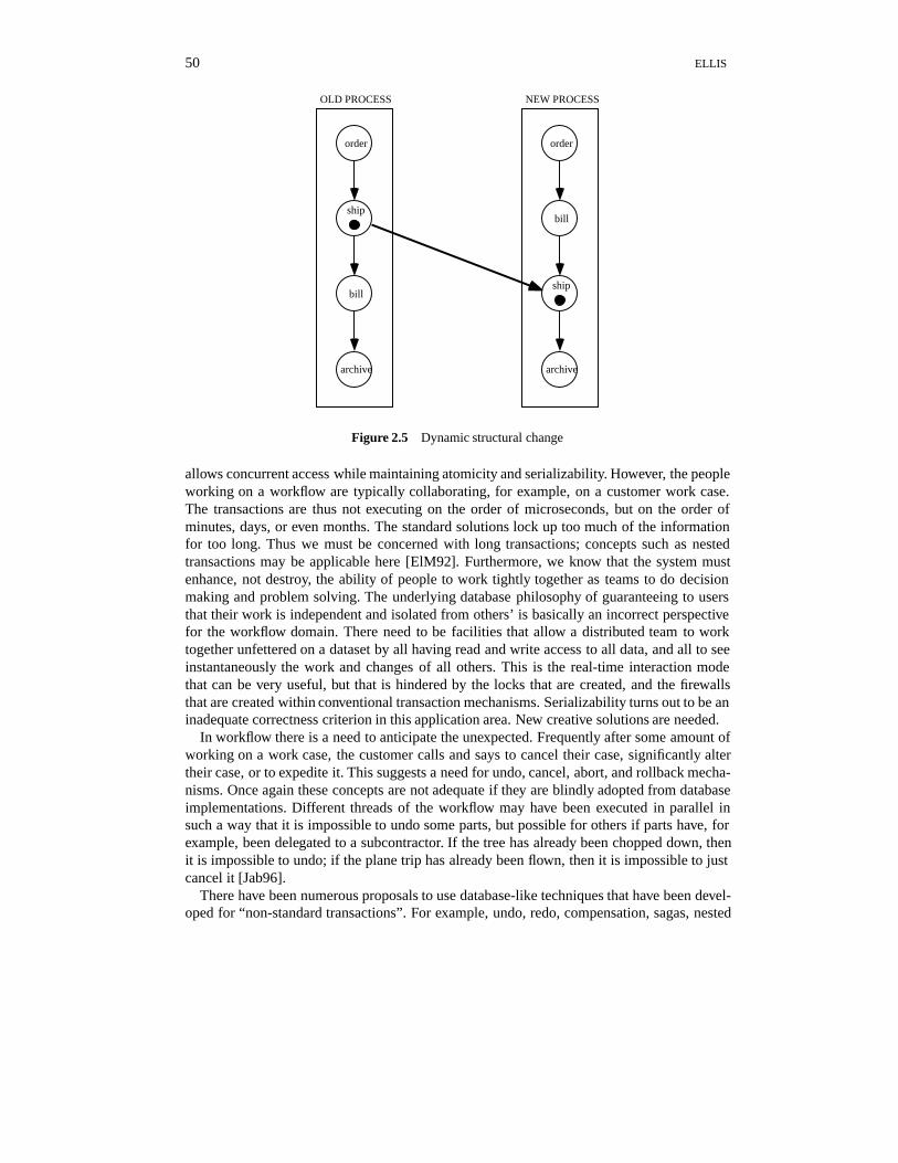
Dynamic change correctness is concerned with tokens which enter the net prior to thechange and do not exit the ICN until some time after the change. Anomalous behavior canbe exhibited by these tokens even if we know that the change maintains static correctness.A simple example of this is the change that includes swapping of the billing and shippingactivities in the example ICN of Figure 2.5. Notice that Figure 2.5 is simply a sub-ICN of thepreviously explained ICN of order processing (Figure 2.3). Tokens that are currently withinthe shipping node when the swap change occurs never encounter the billing activity, so thecompany never gets paid for the goods that are shipped. Suppose that the correctness criterionis that all customer orders must pass through shipping and billing in some order. This anomalyoccurs although the ICN before the change is correct, and the ICN after the change is correct.Similarly, an anomaly occurs if we simply try to enhance the efficiency of the procedure bychanging to perform billing and shipping in parallel. This example depicted in Figure 2.5 issmall and obvious; other examples which occur in ICNs of hundreds of nodes are not at all ob-vious, and difficult to find and correct. By combining some techniques of Petri nets and graphgrammars, Keddara [Ked95] has been able to characterize situations in which this behavior isnon-problematic.
2.7.4 Workflow Transactions
Many notions such as transactions, that have been studied within the database community,are not present in today’s typical workflow products. Concepts of archival storage (datamining), efficient retrieval, transparency (e.g. of distribution), concurrency control, and re-liability/recovery have been conceived within the database community, studied in researchlabs, and implemented in database management products, but have mostly not made their wayinto workflow management systems [Sh95]. This is partly due to thinking of workflow asequivalent to control flow, and ignoring data flows. This is also partly due to the origins ofmany workflow products and companies being non-database companies. Finally, this is partlydue to the need to rethink these concepts within the workflow context, and to not simply copythe database implementations of these concepts. Sometimes the database expert does not havesufficient knowledge or sensibilities about the workflow needs of organizations.
For example, there are clearly multiple people needing to access the workflow informationand system concurrently. Both within a single workflow, and among different workflows,we must enable parallelism. Thus, the database transaction has been suggested because it
50 ELLIS
order
bill
archive
order
bill
archive
ship
ship
OLD PROCESS NEW PROCESS
Figure 2.5 Dynamic structural change
allows concurrent access while maintaining atomicity and serializability. However, the peopleworking on a workflow are typically collaborating, for example, on a customer work case.The transactions are thus not executing on the order of microseconds, but on the order ofminutes, days, or even months. The standard solutions lock up too much of the informationfor too long. Thus we must be concerned with long transactions; concepts such as nestedtransactions may be applicable here [ElM92]. Furthermore, we know that the system mustenhance, not destroy, the ability of people to work tightly together as teams to do decisionmaking and problem solving. The underlying database philosophy of guaranteeing to usersthat their work is independent and isolated from others’ is basically an incorrect perspectivefor the workflow domain. There need to be facilities that allow a distributed team to worktogether unfettered on a dataset by all having read and write access to all data, and all to seeinstantaneously the work and changes of all others. This is the real-time interaction modethat can be very useful, but that is hindered by the locks that are created, and the firewallsthat are created within conventional transaction mechanisms. Serializability turns out to be aninadequate correctness criterion in this application area. New creative solutions are needed.
In workflow there is a need to anticipate the unexpected. Frequently after some amount ofworking on a work case, the customer calls and says to cancel their case, significantly altertheir case, or to expedite it. This suggests a need for undo, cancel, abort, and rollback mecha-nisms. Once again these concepts are not adequate if they are blindly adopted from databaseimplementations. Different threads of the workflow may have been executed in parallel insuch a way that it is impossible to undo some parts, but possible for others if parts have, forexample, been delegated to a subcontractor. If the tree has already been chopped down, thenit is impossible to undo; if the plane trip has already been flown, then it is impossible to justcancel it [Jab96].
There have been numerous proposals to use database-like techniques that have been devel-oped for “non-standard transactions”. For example, undo, redo, compensation, sagas, nested
WORKFLOW TECHNOLOGY 51
transactions, and abort mechanisms [ElM92]. These mechanisms are good innovations for es-tablished exceptions, but are much less useful for true exceptions where the detection pointmay be totally disjoint from the cause point, and where it may be totally impossible to undo.
2.7.5 Further Research Directions and Issues
This chapter has introduced only a few of the workflow research areas. Other areas includedistributed workflow, workflow benchmarking, combining workflow and groupware, real-time interactions, incorporation of goals into workflow systems, incorporation of multimedia,learning and evolving workflow systems, organizational sub-models, social sub-models, andgroup user interfaces. Also, numerous deep problems exist concerning end-user programma-bility by secretaries, clerks, and other non-computer people. Many of these problems remainas inhibitors to successful workflow implementations.
2.8 SUMMARY
This chapter has presented a tour of workflow issues, technology, and challenges. Workflowmanagement systems consist of two components: a modeling component used for the defini-tion, analysis, simulation and restructuring of processes, and an enactment component, calledthe “run-time system” which has a workflow engine to coordinate process steps, and an exe-cution interface for use by the distributed end-users.
Besides presenting workflow definitions, architectures, and models, this chapter has pre-sented a historical perspective that suggests that the human and social factors are very im-portant, and have frequently been ignored in the past. Workflow systems are foremost peoplesystems. This leads to consideration of a meta-model attempting to capture some of the hu-man dimensions of workflow, and the description of some workflow systems and researchprototypes which are attempting to solve some of the hard problems that are still plaguingthe field. A few of these hard problems have been described, including exception handling,interoperability, dynamic change, and workflow transactions.
It is hoped that the work presented herein will raise awareness of work and considerationsthat are paramount for workflow success, and also that this will stimulate good researchers totake up the banner of doing needed research in this fast growing area.
REFERENCES
[Ade92] Ader, M. and Lu, G., The WooRKS Object Oriented Workflow System. OOPSLA92 Exhi-bition, booth 712–714, October 19–21, 1992. Developed as part of the ITHACA Researchproject within the ESPRIT Program.
[Bae93] Baecker, R. (Ed.), Readings in Groupware and Computer Supported Cooperative Work.Morgan Kaufmann Publishers, January 1993.
[Bai81] Bair, J. (Co-editor), Office automation systems: Why some work and others fail. StanfordUniversity Conference Proceedings. Stanford University, Center for Information Technol-ogy, 1981.
[Bai82] Bair, J., Methods for success with new workflow systems. In D. Coleman (Ed.), Group-Ware’92, pages 160–164. Morgan Kaufmann Publishers, San Mateo, CA.
[Bar83] Barber, G., Supporting organizational problem solving with a workstation. ACM Transac-tions on Office Information Systems, 1(1), 1983.
52 ELLIS
[Bra84] Bracchi, G. and Pernici, B., The design requirements of office systems. ACM Transactionson Office Information Systems, 2(2):151–170, April 1984.
[Bro93] Brown, J.S. and Duguid, P., Stolen knowledge. Educational Technology, March 1993.[Bul92] Bull Corporation, FlowPath Functional Specification. Bull S. A., Paris, France, September
1992.[Che76] Chen, P., The entity-relationship model – Toward a unified view of data. ACM Transactions
on Database Systems, 1(1), 1976.[Coo80] Cook, C., Office streamlining using the ICN model and methodology. In Proceedings of the
1980 National Computer Conference, June, 1980.[Cro88] Croft, W. and Lefkowitz, L., Using a planner to support office work. In Proceedings of ACM
COIS’88, pages 55–62, March 1988.[Cro89] Croft, W. and Lefkowitz, L., Planning and execution of tasks in cooperative work environ-
ments. IEEE AI, 1989.[CSCW92] Computer Supported Cooperative Work (CSCW), An International Journal. Kluwer Aca-
demic Publishers, Vol. 1, 1992.[Dav91] Davis, D. B., Software that makes your work flow. Datamation, 37(8):75–78, April 1991.[DeJ90] De Jong, P., Structure and action in distributed organizations. In Proceedings of ACM
COIS’90, pages 1–10, April 1990.[Dum91] Dumas, P., La Methode OSSAD. Les Editions d’Organisation, 1991.[Dys92] Dyson, E., Workflow. Release 1.0, EDventure Holdings, New York, September 1992.[Ede95] Eder, J. and Groiss, H., Interoperability with world wide workflows. Integrated Design and
Process Technology, IDTP Vol.1, December 1995.[Ehr99] Ehrlich, K., Designing groupware applications: A work-centered approach. In Beaudouin-
Lafon, M. (Ed.), Computer Supported Cooperative Work, Trends in Software Series 7:1–28.John Wiley & Sons, Chichester, 1999.
[Ell79a] Ellis, C. A., Information control nets: A mathematical model of office information flow.In Proceedings of the 1979 ACM Conference on Simulation, Measurement and Modeling ofComputer Systems, pages 225–239, August 1979, .
[Ell79b] Ellis, C., OfficeTalk-P: An office information system based upon migrating processes. InNajah Naffah (Ed.), Integrated Office Systems. INRIA, France, 1979.
[Ell80] Ellis, C. A. and Nutt, G. J., Office information systems and computer science. ACM Com-puting Surveys, 12(1):27–60, March 1980.
[Ell82] Ellis, C., OfficeTalk-D: An experimental office information system. In Proceedings of theFirst ACM Conference on Office Information System, June 1982.
[Ell83] Ellis, C., Formal and informal models of office activity. In Proceedings of the IFIP Interna-tional Computer Congress, Paris, 1983.
[Ell91] Ellis, C. A., S. J. Gibbs, and G. L. Rein, Groupware: Some issues and experiences. Commu-nications of the ACM, 34(1):38–58, January 1991.
[Ell95] Ellis, C. and Wainer, J., Goal-based models of collaboration. Collaborative ComputingJournal, 1(1), 1995.
[ElM92] ElMagarmid, A. (Ed.), Database Transaction Models for Advanced Applications. MorganKaufmann, 1992.
[Flo88] Flores, F., Graves, M., Hartfield, B. and Winograd, T., Computer systems and the design oforganizational interaction. ACM Transactions on Office Information Systems, 6(2):153–172,April 1988.
[Gas86] Gasser, L., The integration of computing and routine work. ACM Transactions on OfficeInformation Systems, 4(3):205–225, July 1986.
[Geo95] Georgakopoulos, D. , Hornick, M., and Sheth, A., An overview of workflow management:From process modeling to workflow automation infrastructure. Distributed and ParallelDatabases, 3(22):119–154, April 1995.
[Gru88] Grudin, J., Why CSCW applications fail, In Proceedings of the Conference on ComputerSupported Cooperative Work (CSCW’88), pages 85–93. ACM Press, New York, 1988.
[Har90] Harel, D., et. al., STATEMATE: A working environment for the development of complexsystems. IEEE Transactions on Software Engineering, 16(4), April 1990.
[Hir85] Hirschheim, R. A., Office Automation: A Social and Organizational Perspective. John Wiley& Sons, 1985.
WORKFLOW TECHNOLOGY 53
[Ho86] Ho, C., Hong, Y. and Kuo, T. A., Society model for office information systems. ACMTransactions on Office Information Systems, 4(4):104–131, April 1986.
[Hol88] Holt, A., Diplans: A new language for the study and implementation of coordination. ACMTransactions on Office Information Systems, 6(2), 1988.
[Jab96] Jablonski, S., Bussler, C., Workflow Management. Thomson Computer Press, 1996.[Joh94] Johansen, R., and Swigart, R., Upsizing the Individual in the Downsized Organization.
Addison-Wesley, 1994.[Kar91] Karbe, B., Ramsperger, N., Concepts and implementation of migrating office processes.
Verteilte Kunstliche Intelligenz und Kooperatives Arbeiten, page 136, 4, Internationaler GI-Kongress Wissensbasierte Systeme, Munchen, Germany, October 1991.
[Ked95] Keddara, K., and Rozenberg, G., Dynamic change within workflow systems. In Proceedingsof the ACM SIGOIS Conference on Organizational Computing Systems, August 1995.
[Kel91] Kellner, M., Software process modeling support for management planning and control. InProceeding of the First International Conference on the Software Process, pages 8–28. IEEEComputer Society, October 1991.
[Kre84] Kreifelts, T., Licht, U., Seuffert, P. and Woetzel, G., DOMINO: A system for the specifica-tion and automation of cooperative office processes. In Wilson and Myrhaug (Eds.), Proc.EUROMICRO’84, pages 3–41, 1984.
[Kre87] Kreifelts, T. and Woetzel, G., Distribution and exception handling in an office proceduresystem. In Bracchi and Tsichritzis (Eds) Office Systems: Methods and Tools, pages 197–208, 1987.
[Kre91a] Kreifelts, T., Coordination of distributed work: From office procedures to customizable activ-ities, Verteilte Kunstliche Intelligenz und Kooperatives Arbeiten, page 148, 4, InternationalerGI-Kongress Wisensbasierte Systeme, Munchen, Germany, October 1991.
[Kre91b] Kreifelts, T., et.al., Experiences with the DOMINO office procedure system, In Proceedingsof the ECSCW’91, pages 117–130. Kluwer, Dordrecht, 1991.
[Li90] Li, Jianzhong, AMS: A Declarative Formalism for Hierarchical Representation of Procedu-ral Knowledge. Ph.D. Thesis, Ecole Nationale Superieure des Telecommunications, Paris,France, December 1990.
[Lou92] Loucopoulos, P. and Katsouli, E., Modelling business rules in an office environment. SIGOISBulletin, 13(2). ACM, August 1992.
[Lut88] Lutze, R. and Triumph-Adler, A., Customizing cooperative office procedures by planning.In Proceedings of ACM COIS’88, pages 63–77, March 1988.
[Luq90] Luqi, A., Graph model for software evolution. IEEE Transactions on Software Engineering,16(8), August 1990.
[Mal94] Malone, T. and Crowston, K., The interdisciplinary study of coordination. ACM ComputingSurveys, 26(1):87–120, March 1994.
[Mar91] Martial, F.V., Activity coordination via multiagent and distributed planning. Verteilte Kun-stliche Intelligenz und Kooperatives Arbeiten, page 90, 4, Internationaler GI-Kongress Wis-sensbasierte Systeme, Munchen, Germany, October 1991.
[Med92] Medina-Mora, P. et. al., The Action Workflow approach to workflow management technol-ogy. In Proceedings of ACM CSCW’92, pages 281–288, November 1992.
[Min79] Mintzberg, H., The Structure of Organizations. Englewood Cliffs, 1979.[Nut79] Nutt, G. J. and Ellis,C. A., Backtalk: An office environment simulator. In ICC ‘79 Confer-
ence Record, pages 22.3.1–22.3.5, June 1979.[Nut83] Nutt, G. J., An experimental distributed modeling system. ACM Transactions on Office
Information Systems, 1(2):117–142, April 1983.[Nut89] Nutt, G. J., Beguelin, A., Demeure, I., Elliott, S., McWhirter, J., and Sanders, B., Olym-
pus: An interactive simulation system, In Proceedings 1989 Winter Simulation Conference(Washington, D.C.), pages 601–611, December 1989.
[Nut90] Nutt, G. J., A simulation system architecture for graph models. In Rozenburg, G. (Ed.),Advances in Petri Nets ’90. Springer Verlag, 1990.
[Ost88] Osterweil, L., Automated support for the enactment of rigorously described software pro-cesses. In Proceedings of the Third International Process Programming Workshop, pages
54 ELLIS
122–125. IEEE Computer Society Press, 1988.[Pan84] Panko, R., 35 Offices: Analyzing needs in individual offices. In Proceedings of the Second
ACM-SIGOA Conference on Office Information Systems, June 1984.[Rei92] Rein, G., Organization Design Viewed as a Group Proces Using Coordination Technol-
ogy. Ph.D. Thesis Dissertation, Department of Information Systems, University of Texas atAustin, May 1992.
[Rei93] Rein, G., Singh, B., and Knutson, J., The grand challenge: Building evolutionary technolo-gies. In Proceedings of the HICSS93 Conference, pages 5–8, January 1993.
[Roo68] Roos, L., and Stark, F., Organizational roles. In Lindzey, G., and Aronson, E. (Eds.), Hand-book of Social Psychology, 2nd Edition, 1968.
[Saa94] Saastamoinen, H.T., Markkanen, M.V., Savolainen, V.V., A survey of exceptions in informa-tion systems. University of Colorado Technical Report, CU-CS-712-94, April 1994.
[Saa95] Saastamoinen, H.T., On the Handling of Exceptions in Information Systems, Ph.D. ThesisDissertation, University of Jyvaskyla, November 1995.
[Sar91] Sarin, K. S., Abbott, K. R. and McCarthy, D. R., A process model and system for supportingcollaborative work. In Proceedings ACM COCS’91, pages 213–224.
[Sh95] Sheth, A., and Rusinkiewicz, M., Specification and execution of transactional workflows. InW. Kim (Ed.), Modern Database Systems: The Object Model, Interoperability and Beyond,pages 592–620. ACM Press, New York, 1995.
[Sir84] Sirbu, M., Schoichet, S., Kunin, J. S., Hammer, M. and Sutherland, J., OAM: An officeanalysis methodology. Behaviour and Information Technology, 3(1):25–39, 1984.
[Str89] Strong, D.A. and Miller, S.M., Exception handling and quality control in office operations.Boston University School of Management Working Paper, #89-16. Boston, MA, 1989.
[Suc83] Suchman, L., Office procedure as practical action: Models of work and system design. ACMTransactions on Office Information Systems, 1(4):320–328, October 1983.
[Suc87] Suchman, L., Plans and Situated Action: The Problem of Human–Machine Communication.Cambridge University Press, Cambridge, England, 1987.
[Tsi82] Tsichritzis, D., Forms management. Communications of the ACM, 25(7):453–478, July1982.
[Woo90] Woo, C., SACT: A tool for automating semi-structured organizational communication. InProceedings of ACM COIS’90, pages 89–98, April 1990.
[Whi94] White, T. and Fisher, L., The Workflow Paradigm: The Impact of Information Technology onBusiness Process Reengineering. Future Strategies, Inc., Alameda, CA, 1994.
[WMC] Workflow Management Coalition, Coalition Overview, Reference Model, and Glossary. SeeInternet home page http://www.aiai.ed.ac.uk/WfMC/
[W4] The W4 World Wide Web Workflow product features, 1997. http://www.w4.fr[Zis77] Zisman, M. D., Representation, Specification, and Automation of Office Procedures. Ph.D.
Thesis Dissertation, Wharton School, University of Pennsylvania, 1977.