H uman Machine Interface A nd the S afety of T raffic in E urope Project GRD1/2000/25361 S12.319626 Workpackage 4 Deliverable 4 Recommended Methodology for the preliminary safety analysis of the HMI of an IVIS concept or design V1.01 13/10/05
6 APPLYING HAZOP TO TRAFFIC AND AUTOMOTIVE IVIS 35
6.1 Traffic Safety application of HAZOP 35 6.2 Applying HAZOP to analysis of IVIS 37 6.3 Interim conclusions 40
7 DEVELOPMENT OF A DOP PROCEDURE 41
7.1 DOP applicability within the design process 41 7.2 Assumptions on DOP information requirements 41 7.3 HASTE DOP Guidewords 42 7.4 Initial Review of DOP application 44 7.5 Application of Procedure 49 7.6 Interim Conclusions 49
3
HASTE Deliverable 4 –Recommended Methodology for a preliminary safety analysis of the HMI of an IVIS
8 VALIDATION OF DOP 50
8.1 Selection of IVIS 50 8.2 DOP application – Expert Group 51 8.3 DOP application – Validation 51 8.4 Issues Identified 52 8.5 Analysis of application of DOP 54 8.6 Comparison with other evaluations 54 8.7 Discussion 57 8.8 DOP Validation - Implications 58
9 CONCLUSIONS 60
10 REFERENCES 62
4
HASTE Deliverable 4 –Recommended Methodology for a preliminary safety analysis of the HMI of an IVIS
1 Introduction
1.1 HASTE project overview
Over the last decade many technologies and systems to deliver more information about traffic conditions and other travel related factors to road vehicle drivers have been developed. Some of these systems are now emerging into products for the mass market. Such systems may offer better information to drivers to support safe and efficient journeys through increasingly complex and congested road conditions. However the additional information provided by such systems has to be integrated by the driver into his already demanding task of driving. If such information is difficult for the driver to acquire, control or understand then there may be a negative impact on his driving performance. In light of such concerns it has been considered how any such negative impact of future systems availability, and by inference driving performance, can be minimised. Such systems are generically called IVIS. In this context an IVIS is defined as :- • An IVIS (In-Vehicle Information System) is an In-vehicle Information & Communication System designed for use by the driver while driving.
Source : EC Statement of Principles [1] The aim of the HASTE (Human Machine Interface And the Safety of Traffic in Europe) project is to develop methodologies and guidelines for the assessment of In-Vehicle Information Systems (IVIS). It is therefore implied that such systems must have a means of communicating with the driver. This could be through one or more sensory modalities, i.e. visual, auditory or tactile/haptic interfaces. It is also clear that in most likely scenarios the driver will have some ability to control or influence the behaviour of the IVIS. This will also require some form of system input interface. The way in which information is provided, and control enacted, defines the IVIS Human Machine Interface (HMI).
1.2 HASTE Project Objectives
The overall objectives of the programme of research within HASTE are: • To identify and explore relationships between traffic scenarios in which safety problems
with an IVIS are more likely to occur • To explore the relationships between task load and risk in the context of those scenarios • To understand the mechanisms through which elevated risk may occur in terms of
distraction and reduced Situation Awareness • To identify the best indicators of risk (accident surrogates) • To apply the methods devised to evaluating real systems • To recommend a pre-deployment test regime that is both cost effective and possesses the
validity to predict performance
5
HASTE Deliverable 4 –Recommended Methodology for a preliminary safety analysis of the HMI of an IVIS
• To recommend an approach for the preliminary hazard analysis of an IVIS concept or design
• To review the possible causes of IVIS safety hazards, including those related to reliability, security and tampering
The HASTE project has addressed these objectives by carrying out a series of WorkPackages (WPs) that have individually contributed to individual aspects of the overall project goals. These WPs are defined as follows
WP1 : Development of experimental protocol WP2 : Driver performance and safety WP3 : Validation and specification of test regime WP4 : Safety and risk analysis WP5 : Outreach, users and dissemination WP6 : Final report
This HASTE project deliverable is directly related to the outputs from HASTE WP4. The interrelationships of the HASTE WPs are illustrated in the figure shown below.
WP5
Dis
sem
inat
ion,
use
rs a
nd o
utre
ach
WP1
Development of experimental
protocol
WP2
Driver performance and safety
WP3
Validation and specification of test
regime
WP4
Risk analysis and diagnostics
WP6
Final Report
Establish methods and metrics and define scenarios
Impacts of load on safety
Development of specification
Hazard identificationReliability analysis
and predictive power
WP0
Pro
ject
Man
agem
ent
Figure 1 – HASTE WP interrelationships
6
HASTE Deliverable 4 –Recommended Methodology for a preliminary safety analysis of the HMI of an IVIS
1.3 Addressing assessment methods in HASTE
Three important steps in addressing the formation of assessment methodologies for IVIS are : (1) The refinement of knowledge about the impacts of IVIS on driving performance (WP1 and WP2). The use of an IVIS may have a negative or positive impact on driving. However, since IVIS-related performance decrements are crucial for the final judgement of safety, in HASTE the emphasis is on assessing the negative effects of IVIS use on driving performance. HASTE Deliverable 1 [2] comprised the first phase of this knowledge refinement. It reviewed the potential methods and metrics and the definition of scenarios in which IVIS-related safety problems are likely to occur. These methods, metrics, and scenarios were then used in the definition of various experimental settings as described in HASTE Deliverable 2 [3]. These experiments were the second phase of this process of knowledge refinement. They aimed to identify the best risk indicators for IVIS use during driving. These risk indicators were used for :
(2) The development of a testing regime for IVIS that is both simple and valid (WP3). Both surrogate and real IVIS were used in the development of this testing regime. The conclusions of the tests and their analysis are described in HASTE Deliverable 3 [4] and consequently formed a major input into the HASTE final report, Deliverable 6 [5] of the project. This also contributed to : (3) The formulation of guidelines for the future development of IVIS. These guidelines aimed to provide authorities with a practical pass-fail procedure for IVIS. It was acknowledged in this structure that it is also important to have a means of making some preliminary assessments of a proposed IVIS prior to the expensive process of detailed design, development and product engineering. This aspect of predictive assessment is the subject of a parallel development of assessment methodologies and was carried out within HASTE WP4.
1.4 HASTE Work Package 4
This goal of this HASTE WP was to examine how risk analysis techniques can be applied to carry out early analysis of a proposed IVIS HMI.
1.4.1 HASTE WP4 Objectives The specific objectives of this HASTE WP were as follows • Review the current state-of-the-art concerning the existing techniques for preliminary
safety analysis of more general automotive systems to that specifically relevant to IVIS HMI. Assess the applicability of these approaches for IVIS HMI evaluation
• Identify potential evaluation methodologies for the hazard identification and risk analysis and system safety of an IVIS concept or design.
• Assess the effectiveness of these methodologies by applying them to existing IVIS system designs and validate the method
7
HASTE Deliverable 4 –Recommended Methodology for a preliminary safety analysis of the HMI of an IVIS
• Compare the risk assessment generated with that carried out elsewhere in the HASTE project using other assessment techniques
The results from this comparison process were then used in the finalisation of a methodology for a preliminary safety assessment of an IVIS HMI. Consideration was also given in how this technique can be applied within an industrial design and development process. Consideration was also given into how procedures to assess associated user design issues such as those related to system reliability, security and tamper proofing could be incorporated in an industrial design setting.
1.4.2 HASTE WP4 Task Structure The work within HASTE WP4 was split into three sequential tasks. These tasks are described below. Task 4.1 Identification of Issues : This activity studied the relevant techniques related to hazard identification and risk analysis (e.g. from accident statistics) of automotive systems in general, and assess their applicability to IVIS HMI in particular. It also considered the various representations of risk, hazard and safety used within the context of IVIS operation while driving. It subsequently identified issues that need to be considered for IVIS. It developed the objectives and requirements regarding hazard identification and risk analysis procedures for any IVIS HMI. It also considered issues related to possible future system diagnostics requirements for in-service evaluation. Task 4.2 Formulation of methodology : Using the output from Task 4.1 a methodology was developed to model an IVIS HMI in order to facilitate a hazard assessment. The approach also enabled identification of the possible reasons for these safety hazards. These hazards were related to the performance or behaviour of the components within the concept or design. The influence of other design aspects such as reliability, security and tamper resistance were also considered. Task 4.3 Validation : The methodology developed during Task 4.2 was then applied to IVIS HMIs from real world systems. This included one IVIS HMI also considered within HASTE WP3 and the results from these other trials in this other HASTE WP is compared with the results from within this WP. This validation process enabled a development phase for a methodology and the resultant revised methodology is then defined. This deliverable summarises the work carried out within the three tasks described above and concludes by proposing a IVIS HMI assessment methodology.
1.4.3 Initial HASTE WP4 Analysis The HASTE project overall is considering how IVIS assessments can be carried out using human factors trials, supported by robust experimental data, that will guide product development and subsequently yield overall IVIS system operability for use by the driver while driving. It is also acknowledged that such real-life experimental protocols can only be applied when a “product” has been fully defined and implemented. It is therefore necessary to consider how techniques can be developed that allows evaluation of the potential HMI design of a newly proposed IVIS at an early stage in its lifecycle.
8
HASTE Deliverable 4 –Recommended Methodology for a preliminary safety analysis of the HMI of an IVIS
This also raises the question as to the concept of inferring “risk” and “safety” assessments based upon quantifiable measures of driving performance and/or task efficiency. How does the development of a practical test protocol, using representative users in a real or simulated driving environment, mirror such a parallel approach for a concept or system assessment? Are the two approaches comparable? In order to assess this aspect HASTE WP4 examined the concepts behind the test protocol development of HASTE.
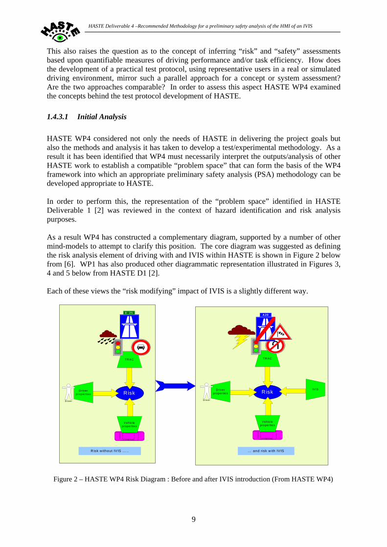
1.4.3.1 Initial Analysis HASTE WP4 considered not only the needs of HASTE in delivering the project goals but also the methods and analysis it has taken to develop a test/experimental methodology. As a result it has been identified that WP4 must necessarily interpret the outputs/analysis of other HASTE work to establish a compatible “problem space” that can form the basis of the WP4 framework into which an appropriate preliminary safety analysis (PSA) methodology can be developed appropriate to HASTE. In order to perform this, the representation of the “problem space” identified in HASTE Deliverable 1 [2] was reviewed in the context of hazard identification and risk analysis purposes. As a result WP4 has constructed a complementary diagram, supported by a number of other mind-models to attempt to clarify this position. The core diagram was suggested as defining the risk analysis element of driving with and IVIS within HASTE is shown in Figure 2 below from [6]. WP1 has also produced other diagrammatic representation illustrated in Figures 3, 4 and 5 below from HASTE D1 [2]. Each of these views the “risk modifying” impact of IVIS is a slightly different way.
Risk
Vehicleproperties
TRAC
Driverproperties
Driver
R isk
Vehicleproperties
TRAC
Driverproperties
Driver
IV IS
R isk w ithout IV IS … .. … and risk w ith IV IS
E 25A20
Figure 2 – HASTE WP4 Risk Diagram : Before and after IVIS introduction (From HASTE WP4)
9
HASTE Deliverable 4 –Recommended Methodology for a preliminary safety analysis of the HMI of an IVIS
HASTE Deliverable 4 –Recommended Methodology for a preliminary safety analysis of the HMI of an IVIS
Figures 2 and 3 above identify the multi-factored interaction between various “environmental” elements in road traffic/vehicle operation. Figure 2 sees the outcome of these interactions as “Risk” or perhaps “level of risk”. Figure 3 sees interaction between the driver, IVIS and environment as resulting in a “behaviour”. This could possibly be interpreted that this behaviour has a “risk” factor built into its definition. Figure 4 attempts to layer the factors within a nested structure, within which driver behaviour is embedded. This is perhaps the least satisfying and unhelpful representation. Figure 5 on the other hand adds a very relevant and often overlooked (or ill defined) element in that of the time dimension within a driving task. In particular the concept of “driver distraction risk” related to driver capacity (variable over time), driver demand (variable over time) and IVIS task complexity (variable over time) is hinted at here. Each of these representations offers slightly different interpretations of the overall concept of HMI interaction between IVIS and driver and its relation to risk and hazard to a degree. They also indicate that there are many interactive aspects of potential risk associated with the use of an IVIS within the context of operation, use while driving and driver behaviour within a dynamic traffic environment. However within HASTE WP4 it has been important to concentrate on those IVIS HMI aspects that focus on operability alone. The approach developed within this deliverable to HASTE therefore is primarily at the driver safety levels of analysis, i.e. that related to direct IVIS and driver interaction. It is acknowledged that this is appropriate for the early evaluation of a concept IVIS HMI, but will need to be supported by other layers of system analysis at appropriate stages in the design and development lifecycle. This is examined in later sections of this deliverable.
1.4.3.2 Issues Identified The first HASTE WP4 report [6] has indicated that the following issues were identified as relevant for preliminary system assessments of IVIS. These are :-
• The models of risk and potential hazard causation potentially attributable to an IVIS function described within HASTE have been discussed. An agreement within the HASTE project on which of these constitutes the most effective description of the core concept that the HASTE risk assessment methodology is intended to encompass.
• Formal descriptions of risk assessment methodology have been given. These will be utilised as the framework within which a preliminary safety analysis methodology for IVIS will be subsequently developed. A further on-going review of other parallel methods utilised within industry/other sectors will be conducted to ensure that an appropriate method is finally defined and evaluated.
• The lack of useable accident data on risk factors related to IVIS has been noted. Clearly this is a consequence of the relative novelty of IVIS functions in road vehicles. Evidence of impacts on driving performance exist from limited research, which will be expanded by HASTE. Accident related data is only available in part for analogous systems. Further inputs are required and will be monitored for relevance and applicability to WP4.
• The relevance of risk assessment methodology to the design, development and manufacture of an automotive product has been noted. The relevance of legal requirements to ensure that products are “safe” and do not contribute to increased injury and/or accident risk have also been noted.
Page 11 of 63
HASTE Deliverable 4 –Recommended Methodology for a preliminary safety analysis of the HMI of an IVIS
To date, there have been several attempts to provide manufacturers and testing authorities with guidelines and/or assessment methods to assess the likely impacts of IVIS on the driving task. Many of these approaches involve the use of some form of checklist. Such checklists potentially provide a tool that enables the identification of likely problems but they do not attempt to quantify safety problems. There is therefore still a requirement for the development of a valid, reliable and efficient tool that will aid manufacturers and testing authorities in their safety evaluation of IVIS before systems are put into production. The current international state of the art in terms of methodologies for assessing the safety implications of IVIS is highly problematic. A major drawback being that the tools and metrics that have been provided thus far do not permit, in any straightforward way, judgements to be made about the safety of a particular IVIS during use while driving. There are, as a result, no criteria which can be used by a manufacturer, a system supplier or the public authorities to determine whether a particular design meets a minimum threshold of safety in actual use.
1.5 Driver Performance and Accident Statistics
Such an approach to define hazards and risks raises the issue of the resulting negative outcomes, namely accidents, and the relevance of accident investigation data in clarifying “real” risks on the road. HASTE Deliverable 1 [2] indicates that :- “Central to the HASTE project is the consideration of “In-Vehicle Information Systems (IVIS)”, i.e. on-board systems that provide information to the driver. IVIS is a collective noun for a very diverse set of devices, with functions varying from navigation and traffic information to feedback on driving ability. In addition to this heterogeneity of IVIS, the diversity of drivers and driving environments complicates a straightforward assessment of whether ‘doing two things at the same time’ (i.e. driving a car and operating an IVIS) compromises traffic safety. The fact that the cost of such technology is decreasing, could mean an increase in use of IVIS in the future.” – Source HASTE D1 The issue identified here is the relevance and contribution of IVIS operation and use within a driving context that may cause degradation of performance in the primary driving task (vehicle control within traffic) to the extent that a hazard, or accident, may be generated. Is there evidence from road traffic accident analysis that would indicate the severity or frequency of such a causation path? Although there are many post-accident investigations and field surveys carried out it is not always possible to gain insights into human distraction issues that may, or may not, have been present within an accident situation. This is particularly true in fatal accident circumstances where loss of any in-vehicle witnesses may compromise the ability to detail the driver actions leading up to the accident.
Page 12 of 63
HASTE Deliverable 4 –Recommended Methodology for a preliminary safety analysis of the HMI of an IVIS
Further complicating this issue is the relative novelty of IVIS like applications that are only now having a market impact and therefore are being exposed to driving populations. It is therefore appropriate to look at real world experience with analogous in-vehicle systems that can provide a driver with a “secondary task”. These may be different to IVIS concepts in detailed design and interaction requirements but may be considered to be a parallel to emerging IVIS. This can include the use of in-vehicle equipment, such as In Car Entertainment (ICE) systems and mobile phones. In the case of this latter analogous application, i.e. mobile phones, considerable concern has been voiced about their impact on driver performance. As experience has been gained with the proliferation of the devices and their usage by drivers while driving, it has become apparent that instances of driver distraction have occurred in relation to phone operation and various national actions have been taken to attempt to control use. Investigations by researchers in experimental evaluations (simulator and road) have added to the body of knowledge. But links with real-world accident statistics remain less clear. A recent example is that given by Mazzae, Garrott, Barrickman and Ranney [7] who reported that from USA data gathered over the 1995-1998 period some “20-30% of crashes involved distraction”. They also state that :
• New communication and information technologies have potential safety and social benefits
• However, new devices may worsen the distraction problem However the link between performance decrement with/without an additional IVIS task, to be investigated within HASTE, and implications to real-world accident performance will remain complex. This will also be true for risk assessment methodologies developed to investigate these potential impacts and their comparability to impacts in eventual real-world use and consequences to risk and accident causation. In this context the potential distraction that may be attributed to IVIS use while driving leading to decreased awareness of the traffic situation and therefore increased risk is again a central feature. It is noted that the earlier EC ADVISORS project [8] attempted to examine how evidence in accident data records could suggest how driver situation awareness problems could have an impact on certain types of road traffic accident. This project, which focussed on examining problems in today's road traffic and the assessment of Advanced Driver Assistance Systems (ADAS) with regard to those problems in the light of safety, network capacity and environmental load, examined accident data records from many European member states. It suggested that lack of details in available accident data hampered associating what types of situation awareness problems are associated with certain types of road traffic accidents. Clearly ADAS functions are potentially more interactive in driver vehicle control than IVIS related functionality but a parallel inference can be made to attempting to link accident data results to new potential IVIS impacts. Manufacturers of IVIS components/systems will be aware of the need to develop marketable items that have customer appeal, ease of use, cost-effectiveness and profitability. Implicit in all of these aspects is a consideration of product safety. This is important in light of both product safety requirements and also driven by a need to consider the design from a product liability aspect.
Page 13 of 63
HASTE Deliverable 4 –Recommended Methodology for a preliminary safety analysis of the HMI of an IVIS
It is therefore important to consider how the industrial design process is performed and consider what methodologies and processes that are applied to assess the safety of a product such as an IVIS. This is examined in the next sections of this deliverable.
Page 14 of 63
HASTE Deliverable 4 –Recommended Methodology for a preliminary safety analysis of the HMI of an IVIS
2 Safety and Safety Cases The objective of the HASTE project is to provide criteria whereby the safety of an In-Vehicle Information System (IVIS) can be assessed for its potential use in a private vehicle. Since IVIS are complex devices it is unlikely that any assessment/certification will be done using the classic “pass/fail” techniques of Statutory Type Approval (STA). Instead it will be necessary for the developer, or importer (if the device originates from outside the EU), to create a Safety Case for its intended use. This approach is already common in other industry sectors, and has recently been added to the STA regulation for vehicle braking as Annex 18 [9].
2.1.1 Key Concepts – Risk and Safety Before any hazardous undertaking takes place it is now usual to perform a risk analysis to see whether it is safe to do so. The term risk is used in a variety of domains, e.g. financial, medical, engineering, and its use and meaning can vary slightly between these domains. For example, the World Health Organisation defines risk as “a probability of an adverse outcome, or a factor that raises this probability”, whereas the IEC/ISO define risk as the “combination of the probability of occurrence of harm and the severity of that harm”. Since IVIS comprise electronic and programmable components, this discussion will follow the definitions and concepts in IEC 61508 [10]. A hazard is a “potential source of harm”, and harm is “physical injury or damage to the health of people either directly or indirectly as a result of damage to property or to the environment”. With each hazard can be associated a risk, which is the “combination of the probability of occurrence of harm and the severity of that harm”. Tolerable risk is “risk which is accepted in a given context based on the current values of society”, and this leads directly to the definition of safety, which is “freedom from unacceptable risk”. An alternative way of writing the definition of risk is as follows:
risk = probability of occurrence × degree of severity of harm Therefore to reduce a risk either of these two factors can be used, e.g.
• A reduction in the probability of occurrence of road traffic accidents at night can be achieved by having good headlights on vehicle, and also by installing good streetlights.
• A reduction in the severity of harm during a road accident can be achieved by
providing crash barriers between carriageways, as well as by having airbags for the vehicle occupants.
For an IVIS a hazard can occur either because it fails to function correctly, or because the driver does not interact with it properly, or because the driver is distracted from the primary driving task whilst using the IVIS.
Page 15 of 63
HASTE Deliverable 4 –Recommended Methodology for a preliminary safety analysis of the HMI of an IVIS
There are thus three scenarios:
1. A fault1 in a component, or in the design, of the IVIS can lead to an error2 in the state of the IVIS, which in turn can lead to a failure3 to function correctly. This is the model normally used when analysing the functional system safety of such systems. However, this is not the scenario being considered by the HASTE project and so it will not be discussed further.
2. A mistake4 by the driver when operating the IVIS can lead to an error in the state of
the IVIS, which in turn can lead to a failure to function correctly. In this situation the IVIS is performing as intended, but it has been given incorrect data. Alternatively the IVIS can provide the correct result, but the driver makes a mistake when interpreting the results.
3. The driver is distracted by the IVIS and this leads to an inability of the driver to
control the vehicle in a safe manner, which in turn can lead to a traffic safety failure, e.g. a conflict situation.
In order to produce a safe system it is necessary to reduce the risks associated with each hazard to a tolerable, or acceptable, level. We must therefore first consider the IVIS as it might be without any safety features, and identify the hazards that would be associated with such a system. The risk associated with each identified hazard must then be reduced to an acceptable level as shown in Figure 6 below.
IVIS without safety
considerations
Risk to meet required level
of safety
Actual Remaining
Risk Increasing Risk
Necessa ry minimum risk reduction
Actual risk reduction
Figure 6 – Risk Reduction
1 Fault – abnormal condition that may cause a reduction in, or loss of, the capability of a functional unit to perform a required function [IEC 61508] 2 Error – discrepancy between a computed, observed or measured value or condition and the true, specified or theoretically correct value or condition [IEC 61508] 3 Failure – termination of the ability of a functional unit to perform a required function [IEC 61508] 4 Mistake – (or human error) human action or inaction that can produce an unintended result [IEC 61508]
Page 16 of 63
HASTE Deliverable 4 –Recommended Methodology for a preliminary safety analysis of the HMI of an IVIS
In order to reduce the risk either the degree of severity of harm should be reduced by a suitable design, or the probability of occurrence reduced by suitable means. If the degree of severity of harm cannot be reduced to an acceptable level then the safety-related functions must themselves be reliable, i.e. they must have safety integrity5. The concept of ALARP (As Low As Reasonably Practicable) recognises that it is not necessary, indeed it is impossible, to achieve zero risk or “absolute safety”. It also provides an argument that may be used when the functionality of a system is considered to be very desirable, but the risks associated with it are higher than one would normally wish to have.
UNACCEPTABLEREGION(Risk cannot be justifiedexcept in extraordinarycircumstances)
TOLERABLE only if riskreduction is impracticalor if its cost is grosslydisproportionate to theimprovement gained
THE ALARP REGIONRisk is undertaken onlyif a benefit is desired
BROADLYACCEPTABLEREGION
NEGLIGIBLE RISK
(No need fordetailed working todemonstrate ALARP)
TOLERABLE if cost ofrisk reduction would exceedthe improvement gained
The lower the risk, theless, proportionately, itis necessary to spend
to reduce it
Figure 7 – Levels of Risk and ALARP
Figure 7 shows three situations.
1. The probability is so high, or the outcome is so unacceptable, that the risk cannot be justified on any grounds.
2. The risk is, or has been made, acceptable or so small as to be insignificant. 3. The risk is between (1) and (2).
Since there is no such thing as zero risk, the law of diminishing returns comes into force as greater and greater effort is made to reduce the risk towards zero. Thus once situation (2) has been reached, the risk should be made as small as practicable, rather than as small as possible. 5 Safety Integrity – Probability of a safety-related system satisfactorily performing the required safety functions under all the stated conditions within a stated period of time. [IEC 61508]
Page 17 of 63
HASTE Deliverable 4 –Recommended Methodology for a preliminary safety analysis of the HMI of an IVIS
In situation 3 above, a balance has to be struck between the costs required to reduce the risk and the benefits that will be gained from the functionality of the system. The principle that the risk should be ALARP may be used when the function is highly desirable but a risk level that is strictly acceptable, according to the usual criteria, cannot be (reasonably) achieved. The best examples of the use of the ALARP principle come from the medical sector, which may permit the use of equipment with a relatively high probability of failure when it is the only thing that can help a very sick person. In general the ALARP principle will be applied in such a way that the higher or more unacceptable the risk is the more, proportionately, those responsible for the risk would be expected to spend to reduce it.
2.1.2 Safety Case A Safety Case is a formal presentation of evidence, arguments and assumptions aimed at providing assurance that a system has met its Safety Requirements and that the Safety Requirements are adequate. At the beginning of a project consideration needs to be given to the logical argument that will be used to demonstrate that the final IVIS is safe to use. This can be structured using Goal Structured Notation in a manner that is shown in Figure 8. Objectives, or goals, are sub-divided into sub-goals until a means of demonstrating those goals can be identified. These means will then form the safety validation part of the system development process.
Top Goal
Sub-Goal 2Sub-Goal 1 Sub-Goal 3
Means A Means B
Figure 8 – Example of Goal Structured Notation
Goal Structured Notation can also be used to present a Safety Case, though an alternative method is to use a Claims-Argument-Evidence diagram, as shown in Figure 9. Using this method an item of evidence, e.g. the results of some tests, created during the development process is used to support a sub-claim. These sub-claims are then brought together in an argument to demonstrate the validity of the top claim.
Page 18 of 63
HASTE Deliverable 4 –Recommended Methodology for a preliminary safety analysis of the HMI of an IVIS
Evidence A Evidence B
Claim
Sub-Claim 1 Sub-Claim 2
Figure 9 – Example of a Claims-Argument-Evidence Diagram It is important to plan the creation of a Safety Case very early in the development process since it will be necessary to collect the evidence that will be used to support it at all stages of the lifecycle. The collection of such data retrospectively is at best difficult and expensive, and at worst impossible. Care must also be taken when judging the depth and strength of the evidence that is being used. Some items of evidence will be more compelling than others, and this needs to be taken into consideration when judging the effectiveness of the Safety Case as a whole. A Safety Case should contain all the information necessary to assess the safety of a system to the required SIL, the higher the SIL the greater the level of detail that will be necessary. A good Safety Case will provide information that will make an assessor comfortable with the reliability, availability, maintainability and usability properties of an IVIS. The typical contents of a Safety Case, drawn from Ward, Jesty, Carsten and Fowkes [11] are as follows:
• Definition of the system – this defines the target of evaluation in an unambiguous manner. It should describe the system under consideration, how it interfaces with other systems, and how it is intended to be used. It also describes the structure of the system, and lists its component parts.
• Quality Management Report – this provides the evidence that a sound quality
assurance process has been performed. It should also include an analysis as to why the activities performed by the developer were sufficient.
• Safety Management Report – this provides evidence that the activities defined in the
Safety Plan were all carried out. It should include the results of the various safety (hazard) analyses, and a list of all the hazards identified (hazard log). It should also include an analysis as to why the activities performed by the developer were sufficient.
Page 19 of 63
HASTE Deliverable 4 –Recommended Methodology for a preliminary safety analysis of the HMI of an IVIS
• Technical Safety Report – this explains the technical principles that assure the safety of the design. It should include the (safety) validation reports for each component, including the HMI issues. It should also include an analysis as to why the activities performed by the developer were sufficient.
• Related Safety Cases – this should provide reference to any Safety Cases for other
vital systems that contribute to the functional totality of the system. • Conclusion – this should form an analysis as to why the activities performed by the
developer, and the system attributes, are sufficient. These elements of a safety case have to be constructed within the design, development and manufacturing process applied within industry. It is therefore necessary to consider how this process occurs as it forms a definition of a framework for the development of an IVIS product. It also consequently helps to define the environment within which a preliminary safety analysis in particular would be carried out. This is considered in the following section in this deliverable.
2.1.3 Other points of relevance to HASTE It is noted above that the first scenario that can cause a hazard is a fault. However in the context of HASTE WP4 an assessment is being made of the potential for a methodology to assess the attributes of an IVIS HMI at an early stage in concept development. It is likely that at such a stage this concept may not be fully understood to enable all faults to be fully identified in an eventual refined design. It was therefore concluded that consideration of potential system faults would fall outside of the scope of this HASTE WP4 analysis, and is not considered in detail in later sections. However it should be noted that fault conditions could form a cause of eventual risk in driver and IVIS interaction. For example a real-world IVIS that suffers from failed or intermittent functioning in use may cause different impacts on driver behaviour than that encountered in “normal” operation. Later sections of this deliverable will consider how such fault conditions, and their impacts, should be considered within overall system assessments within which any HASTE WP4 methodology would exist.
Page 20 of 63
HASTE Deliverable 4 –Recommended Methodology for a preliminary safety analysis of the HMI of an IVIS
3 System Design
3.1 Overview
Future IVIS systems to provide driver information and assistance as envisaged here will be based on IT and communications infrastructures and essentially electronic in nature. It may therefore be possible for the IVIS applications to be so designed as to generate system diagnostics data and, if possible, analysis. This may be particularly useful to enable future field investigations of behavioural patterns associated with such devices. For example, any IVIS that required driver inputs or other action in relation to IVIS information supply could generate operational logs for future use. Careful consideration would have to be given to what the important parameters were that may, or should, be captured by any such system, and what the implications may be for both legal considerations. Ownership of data, data protection legislation, methodologies for data collection, collation and analysis are all applicable points that would need to be investigated and assessed. System design for an automotive product, or a product that may be used in an automotive context, may also need to consider, and assess, possible use and abuse. Therefore design targets for security and tamper proofing of systems may have some future implications in relation to countering higher risk use and/or involvement in an accident and consequently could have implications for both user and manufacturer. Assessment of these features of IVIS design may also have to be taken into account in a risk analysis. This may also have consequences to how and where risk assessment, design evaluation procedures are carried out and recorded in relation to eventual “legal” use. Further comment on this aspect is given below.
3.2 Legal Issues
3.2.1 Automotive Legislation In the context of HASTE WP4 there are also some potential legal issues to be considered. The assessment of the attributes of an automotive product that in some way has an implication to “safety” in normal operation and in dangerous, i.e. road traffic accident, circumstances is of course at the centre of much of the national and international legal instruments that define how vehicles are constructed. Legal requirements exist for many elements of complete vehicles and their sub-systems. Many of these items of legislation are supported by practical test methods to evaluate whether a particular vehicle design meets a particular target performance. Most of these are repeatable engineering test methods that can be applied to any vehicle covered by the relevant legislation. As such they do not involve “human” involvement in the system aside from human surrogate representations such as crash test dummies, or representations of human anthropometric diversity to assess occupant restraint system design and the like.
Page 21 of 63
HASTE Deliverable 4 –Recommended Methodology for a preliminary safety analysis of the HMI of an IVIS
Such regulatory control through national and international laws, EC directives, ECE regulations etc form an influential group of performance targets that vehicle manufacturers must comply with to allow the products to be sold in specific markets. They are therefore engineering criteria. However when we consider IVIS type systems and their impact on road safety then it is by implication that it is the direct interaction of drivers with an IVIS system that lies at the core of perceptions of increased risk/decreased safety. Therefore assessment of such systems must in some way take into account the effects that this human interaction has with this risk assessment.
3.2.2 Identification of Issues The following issues were therefore identified within WP 4:
• The models of risk and potential hazard causation potentially attributable to an IVIS function described within HASTE have been discussed. An agreement within the HASTE project on which of these constitutes the most effective description of the core concept that the HASTE risk assessment methodology is intended to encompass.
• Formal descriptions of risk assessment methodology have been given. These will be
utilised as the framework within which a preliminary safety analysis methodology for IVIS will be subsequently developed. A further on-going review of other parallel methods utilised within industry/other sectors will be conducted to ensure that an appropriate method is finally defined and evaluated.
• The lack of useable accident data on risk factors related to IVIS has been noted.
Clearly this is a consequence of the relative novelty of IVIS functions in road vehicles. Evidence of impacts on driving performance exist from limited research, which will be expanded by HASTE. Accident related data is only available in part for analogous systems. Further inputs are required and will be monitored for relevance and applicability to WP4.
• The relevance of risk assessment methodology to the design, development and
manufacture of an automotive product has been noted. The relevance of legal requirements to ensure that products are “safe” and do not contribute to increased injury and/or accident risk have also been noted. The conclusions of some previous research (RESPONSE) have been noted in this respect but a further review of other research sources in this field will be carried out as information becomes available.
Page 22 of 63
HASTE Deliverable 4 –Recommended Methodology for a preliminary safety analysis of the HMI of an IVIS
4 Industrial Product Lifecycle impacts
4.1 Scope of this work
Previous work in safety-related systems assessment (e.g. DRIVE Safely [12], PASSPORT [13], MISRA [14]) has developed a process called “Preliminary Safety Analysis” (PSA) that can be used to identify the safety properties of a concept system. The HASTE project has asked whether is it possible to define a “PSA”-like process that can be applied to analysis of the human factors aspects of a concept, specifically those related to an IVIS (In Vehicle Information System). This section examines the relevance of safety assessment techniques developed for use within the industrial design process. It also considers the relevance and applicability of these approaches for an IVIS development, within an automotive industry context, and identifies possible processes for HMI assessment. Subsequent sections will later identify how such existing approaches can be developed into a process specifically address IVIS HMI issues and can be applied within an industrial design product development lifecycle. Note that this process is exclusively concerned with human/machine interaction issues. Any functional safety investigations and issues are considered to be covered by existing practices. Where there is direct relevance to HASTE further details are given.
4.2 Guidance on product development processes
A number of activities, standards and guidelines referring to the engineering of advanced electronic systems in road vehicles may be observed. These include: • IEC 61508 [10]: generic standard for safety-related electronic systems • The MISRA Guidelines [14]: automotive implementation of IEC 61508 concepts • FAKRA: German activity developing an automotive version of IEC 61508 for eventual
publication as an ISO standard • RESPONSE: a sequence of EU projects investigating legal and human factors issues
associated with ADAS (advanced driver assistance systems) [15] Broadly speaking, electronic systems in vehicles may be classified into one of three types: • Control systems: these are systems that are responsible for the direct control of functions
or equipment on a vehicle. These systems include functions such as engine management and stability control. These systems may be distinguished from the next two categories in that they generally make decisions based on observed parameters (including the driver’s control inputs) without requiring driver intervention. Therefore they do not involve any direct interaction with the driver (in the sense of requiring human decisions to be input), or with adjacent vehicles, or with the infrastructure.
Page 23 of 63
HASTE Deliverable 4 –Recommended Methodology for a preliminary safety analysis of the HMI of an IVIS
• Advanced driver assistance systems (ADAS): these are systems that utilize additional data (e.g. from sensors, and/or vehicle–vehicle communications, and/or vehicle–infrastructure communications) to implement higher-level functions e.g. adaptive cruise control, collision avoidance. These systems may have interactions with the driver, typically through an HMI.
• In-vehicle information systems (IVIS): these are systems that principally exist to communicate information with the driver. They may or may not have safety implications depending on their interaction with the other systems on the vehicle.
The scope of this work is to provide a means for assessing any safety implications of IVIS based on human factors issues alone. It is assumed that the following issues (the list is not intended to be exhaustive) are covered by existing standards and guidelines: • Functional safety – IEC 61508, MISRA Guidelines, etc. • EMC – Directive 2004/104/EC, ISO 11451, ISO 11452, etc. • Crashworthiness – safety of interior fittings, etc. The following “decision matrix” can be used to determine whether or not the HASTE process should be applied. It is acknowledged that this may need further refinement with further experience has been gained on applying it to future systems and applications. Table 1 : HASTE Decision Matrix Broad classification of system Functional Safety Issues Human Factors Issues Control system IEC 61508 etc. Not applicable ADAS IEC 61508 etc. RESPONSE IVIS See below HASTE
4.2.1 Checklist for functional safety It is not normally expected that an IVIS will have functional safety properties, but this must always be confirmed and the reason for the decision documented. An initial step is to determine whether the system performs any of the following types of functions. If so, then it should be subjected to a functional safety analysis according to IEC 61508, the MISRA Guidelines, etc. to determine whether there are any functional safety requirements. • Functions related to the direct control of the vehicle by degradation or change in control
functions (e.g. engine, transmission, brakes, suspension, active steering, speed limitation devices), or by affecting the driver’s position (e.g. seat or steering wheel positioning) or by affecting the driver's visibility (e.g. dipped beam or windscreen wiper).
• Functions related to driver, passenger and other road user protection (e.g. airbag and safety restraint systems)
• Functions which when disturbed cause confusion to the driver or other road users (such as incorrect operation of external lighting, wrong information from warning indicators, lamps or displays related to the two previous groups of functions that might be observed by the driver; acoustical disturbances e.g. incorrect operation of anti-theft alarm or horn)
• Functions related to vehicle data bus functionality, by blocking data transmission on vehicle data bus systems, which are used to transmit data, required to ensure the correct functioning of other functions.
Page 24 of 63
HASTE Deliverable 4 –Recommended Methodology for a preliminary safety analysis of the HMI of an IVIS
• Functions which when disturbed affect vehicle statutory data, e.g. tachograph, odometer. This means for example, that a stand-alone IVIS would not be expected to have functional safety properties; but if the IVIS function is integrated within a system that is providing an HMI to control functions such as seat positioning then the overall system will have functional safety properties. It may be possible that novel IVIS functions may be at first introduced as an individual feature independent of other automotive systems on the vehicle, and subsequently over time and with successful market uptake become realised in a more integrated functionality within future vehicles. It is clear that with such a potential technology migration for a particular product or system feature that an early safety analysis may not apply generically to a later implementation. Therefore any exclusion from safety case analyses for a stand-alone IVIS, i.e. considered not to have functional safety properties, should be noted in the safety case, for future reference to more integrated later functionality development. It should also be noted that interpretation of whether an IVIS has functional safety properties is also complex. An example may be IVIS generated information that is either inadequate for the driver’s needs or is delivered in inappropriate timing (e.g. navigation turn guidance delivered too late for negotiating the appropriate manoeuvre). In this case the IVIS may potentially have an impact on the third functional safety requirement listed above, i.e. …functions which when disturbed cause confusion to the driver or other road users”. Clearly safety assessments of a specific IVIS would have to take careful note of the specific functionality available within that IVIS in this respect and consider whether there were functional safety properties.
4.2.2 Relationship to vehicle and system engineering Standards such as IEC 61508 [10] are based on a safety lifecycle that is intended to be conducted in parallel with the overall engineering process for a system. The standard was developed against the background of industrial process control. In this context, there is an item of “equipment under control” (EUC). The EUC may have a control system. Safety functions are added separately to mitigate against hazardous states of the EUC and/or its control system. The safety functions are implemented either in the EUC control system, or in a separate safety system. IEC 61508 and its safety lifecycle applies to these safety functions when they are implemented in an electrical system, an electronic system or a “programmable electronic system”. While many aspects of IEC 61508 are applicable to the engineering of vehicle systems, the safety lifecycle does not align well to the traditional vehicle engineering model; in particular: • Both vehicles and their electronic systems are developed on the basis of a number of
iterative cycles and “samples”; • Final validation is performed before the products are released to sale (e.g. through Type
Approval) rather than during installation and commissioning.
Page 25 of 63
HASTE Deliverable 4 –Recommended Methodology for a preliminary safety analysis of the HMI of an IVIS
The Figures 10 below illustrates the safety lifecycle shown in IEC 61508 [10]. Figures 11 and 12 show some example lifecycles from existing standards and research related to the industrial design process drawn from the EC project EASIS [16]. These show different representations of the detail of the design, development and manufacturing process. However both acknowledge the sequential nature of the process leading from initial design concepts, through increasing product specification and detail, leading to manufacture of a mass market product.
Safety requirementsallocation5
Overall safetyrequirements4
Hazard andrisk analysis3
Overall scopedefinition2
Concept1
Safety-relatedsystems:E/E/PES9
Realization
Overall planning
6 7 8
Overall installationand commissioning12
Overall safetyvalidation13
Overall operation,maintenance and repair14 Overall modification
and retrofit 15
Decommissioningor disposal16
10
Realization
Safety-relatedsystems:
other technology 11
Realization
External riskreductionfacilities
Back to appropriate overall safety lifecycle
phase
O&M
SV
I&C
Figure 10: IEC 61508 safety lifecycle [10]
Page 26 of 63
HASTE Deliverable 4 –Recommended Methodology for a preliminary safety analysis of the HMI of an IVIS
Simulation-based vehicle development
SOPM2 M3M1
Con
M0
0
3
Phase 1 2
Hardware support
Prototype B
Prototype AMules
M4
Management milestone
Figure 11: Generic vehicle development lifecycle adapted from EASIS [16]
Requirements engineering
System design
Implement-ation
System test Validation
Requirements engineering
Typical software “V” cycle (iterated)
Typical software “V” cycle (iterated)
Productionization Series production
Requirements analysis
Post Job #1 support
“A” sample
“B” sample
“C” sample
“D” sample
Figure 12: Generic system development lifecycle adapted from EASIS [16]
Page 27 of 63
HASTE Deliverable 4 –Recommended Methodology for a preliminary safety analysis of the HMI of an IVIS
4.3 Application of IVIS assessments
Clearly the product development lifecycles identified above indicate the sequential progression of initial concepts to mock-ups, engineering prototypes and eventual manufacture ready approved design. They indicate that in an industrial context design processes have to operate within a complex procedure that includes incremental development of systems and integration to refine a design from an “idea” to a finally accepted defined design. If no relevant HMI evaluations are carried out within this process then it is possible that HMI operability risks may become built-in to the design and difficult or impossible to remedy close to manufacture. It is therefore relevant to consider within the objectives of HASTE to consider how such a risk assessment or operability study can be scheduled and delivered within a concept development process. We will now consider how such a procedure (called a Driver Operability Procedure – DOP) can be developed and used. The following figure shows the scope of the area of applicability for the DOP methodology proposed later in this document. It identifies that very early concept stages may not contain enough detail of HMI design to enable meaningful analysis to take place. At this initial stage concept development should take appropriate note of published design guidelines, standards and regulations to guide development. When a more detailed concept specification has been developed prior to prototype development then a DOP can be applied. It also identifies that a Preliminary Safety Assessment analysis (PSA) is complimentary to that proposed for a HASTE DOP. The PSA can address and identify areas of IVIS design at an initial concept stage that may relate to potential use and abuse issues for a specific IVIS that should then be taken into account in system design and development.
PSA
Concept Prototype Product
Experimental protocol
HASTE DOPCritique e.g. design guidelines, standards, regulations
PNCAP
Figure 13: Scope of HASTE DOP
In this context, “concept” is understood to mean an idea or a feature request. “Prototype” means any kind of pre-production sample. “Product” means production-intent samples, volume production and also covers in-service issues.
Page 28 of 63
HASTE Deliverable 4 –Recommended Methodology for a preliminary safety analysis of the HMI of an IVIS
5 Approaches to risk/hazard analysis In this section, the possible alternative approaches to risk and/or hazard analysis are explored, with particular reference to their suitability for application to IVIS. In general, any risk or hazard analysis process consists of the following basic steps: • Identify the risks or hazards associated with a system or process • Classify them in some way • Record the results of the analysis to permit review at a later stage.
5.1 PASSPORT PSA
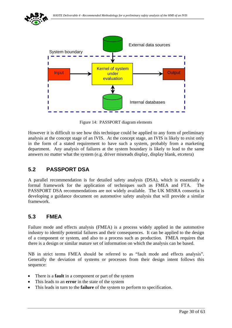
The PASSPORT process for preliminary safety analysis was developed during the eponymous DRIVE II project [13]. It was originally developed for analysis of what where then called “road transport telematic” systems, and has subsequently been adopted for in-vehicle systems by the MISRA Guidelines. A PASSPORT PSA consists of the following stages: • Model the system under evaluation using a modified form of context diagram • Carry out a “what if” analysis on scenarios to determine potential hazards of the system • Carry out a “what causes” analysis on these potential hazards • Determine top-level safety requirements for the system. “What if” analysis is essentially an informal form of FMEA, and “what causes” an informal form of FTA (see below). PASSPORT PSA can be applied when a system is only at the concept stage, and has the advantages that there does not need to be a design for it to be applied and that safety requirements can be considered for all stages of a system specification and design. It provides a way to apply a structured approach to what are essentially informal analyses of informal ideas or designs. The approach has to be applied up to the system boundary, i.e. the system is treated as a “black box” and any failures are assumed to occur at the “interfaces” or “boundary elements”, namely the point at which information enters or leaves the system. The figure below shows the “PASSPORT diagram” that is the modified context diagram of the system used for carrying out the analysis.
Page 29 of 63
HASTE Deliverable 4 –Recommended Methodology for a preliminary safety analysis of the HMI of an IVIS
Kernel of systemunder
evaluation
Internal databases
External data sources
Input Output
System boundary
Figure 14: PASSPORT diagram elements
However it is difficult to see how this technique could be applied to any form of preliminary analysis at the concept stage of an IVIS. At the concept stage, an IVIS is likely to exist only in the form of a stated requirement to have such a system, probably from a marketing department. Any analysis of failures at the system boundary is likely to lead to the same answers no matter what the system (e.g. driver misreads display, display blank, etcetera)
5.2 PASSPORT DSA
A parallel recommendation is for detailed safety analysis (DSA), which is essentially a formal framework for the application of techniques such as FMEA and FTA. The PASSPORT DSA recommendations are not widely available. The UK MISRA consortia is developing a guidance document on automotive safety analysis that will provide a similar framework.
5.3 FMEA
Failure mode and effects analysis (FMEA) is a process widely applied in the automotive industry to identify potential failures and their consequences. It can be applied to the design of a component or system, and also to a process such as production. FMEA requires that there is a design or similar mature set of information on which the analysis can be based. NB in strict terms FMEA should be referred to as “fault mode and effects analysis”. Generally the deviation of systems or processes from their design intent follows this sequence: • There is a fault in a component or part of the system • This leads to an error in the state of the system • This leads in turn to the failure of the system to perform to specification.
Page 30 of 63
HASTE Deliverable 4 –Recommended Methodology for a preliminary safety analysis of the HMI of an IVIS
FMEA is therefore, strictly speaking, concerned with identifying faults and determining what failures could result. A further issue that has to be considered is the system boundary and the point at which the effects (failures) are manifest. There are usually three boundaries that have to be considered: • The boundary of the “target of evaluation” – the system, subsystem or component on
which the analysis is being performed; • The system boundary (usually the point at which the systems sensors and actuators
observe and act on the plant under control); • The event boundary at which the hazardous occurrence will be observed (usually the
vehicle).
5.4 FTA
Fault tree analysis (FTA) is a process applied to the same set of data used for FMEA, but the process is run “in reverse”, starting from a specified failure and exploring the faults that could lead to it. Essentially each failure is decomposed into an hierarchy of lower-level events that could cause it, with the analysis following down to the level at which a basic event occurs (e.g. a wire breaks) or a fault is identified in an item for which a separate analysis is available. FTA is usually presented in a tree-like structure, with the failure at the top of the tree and the combination of events leading to it presented underneath. Multiple events can be combined with “AND” gates (i.e. they must all occur for the next level event to occur), or with “OR” gates (i.e. if one or more occurs, then the next level event will occur). FTA is particularly useful for calculating predicted failure rates for systems, as individual low-level fault probabilities can be combined
Page 31 of 63
HASTE Deliverable 4 –Recommended Methodology for a preliminary safety analysis of the HMI of an IVIS
Failure that causeshazard in question
Faultevent
Fault event
&
B C A B
| &
|
Faultevent
A
|
Faultevent C
Basic event
Figure 15: Example fault tree
5.5 HAZOP
Hazard and operability study (HAZOP or sometimes HAZOPS) is another form of hazard analysis that was originally developed in the chemical engineering industry but has now found wider applications [17]. This has found HAZOP applied successfully to many sectors and to systems based upon various types of technology (electrical, hydraulic, etcetera) and to many different types of systems. A HAZOP analysis starts with a postulated deviation from design intent (effectively the “error” in the 3-step event sequence described above) and examines both what could have caused the error (i.e. the fault that caused it) and the hazard it could lead to (i.e. the failure resulting from it). HAZOP is based on a series of entities, attributes and guidewords, and the hazard analysis is conducted by asking questions in the form:
What if [entity].[attribute] = [guideword] ? The entity is the lowest level of component, system or function that will be examined in the analysis. The attribute is an identifiable state or property of the entity. The guideword describes a deviation from the intended design behaviour. There is a basic standard set of guidewords although these need to be interpreted in the context of the analysis being undertaken.
Page 32 of 63
HASTE Deliverable 4 –Recommended Methodology for a preliminary safety analysis of the HMI of an IVIS
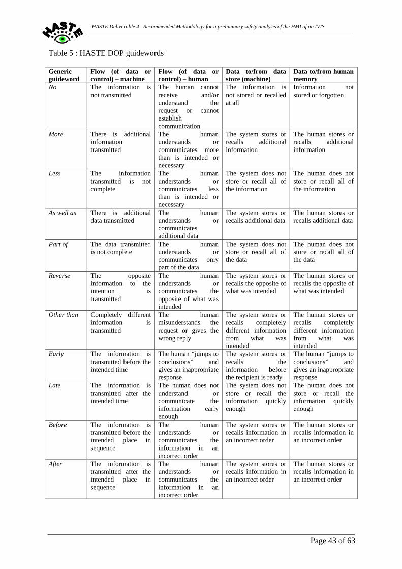
The standard guidewords and their generic meanings are shown in the Table below: Table 2 : HAZOP guidewords and meanings [17] Generic properties
Meaning
No The complete negation of the design intention – no part of the intention is achieved and nothing else happens
More A quantitative increase over what was intended Less A quantitative decrease over what was intended As well as All the design intention is achieved together with additions (i.e. a
qualitative increase over what was intended) Part of Only some of the design intention is achieved (i.e. a qualitative decrease
over what was intended) Reverse The logical opposite of the intention is achieved Other than Complete substitution, where no part of the original intention is achieved
but something quite different happens Timing Meaning Early Something happens earlier than expected relative to clock time Late Something happens later than expected relative to clock time Before Something happens before it is expected, relating to order or sequence After Something happens after it is expected, relating to order or sequence An example question, applied to a valve controlling pneumatic or hydraulic pressure in a system, would be:
What if Valve.Position = Maximum ? Here the generic “more” property has been identified with a specific state of the entity. HAZOP can be applied to a concept (although it requires some sort of design to exist) and also to operational conditions. It is considered to be particularly effective for new systems or novel technologies. The relationship between FMEA, FTA and HAZOP may be summarized by the following figure.
Page 33 of 63
HASTE Deliverable 4 –Recommended Methodology for a preliminary safety analysis of the HMI of an IVIS
Start with
single causePossible consequences
Possible causes
Start with single consequence
Start with single deviation (error)
Possible consequences
Possible causes
HAZOP
FTA
FMEA
Figure 16: Comparison of FMEA, FTA and HAZOP
5.6 Evaluation of possible safety analysis approaches
The techniques outlined in the sections above were evaluated for their applicability for IVIS HMI assessment. The following table is a summary of the evaluation carried out and indicates their applicability to IVIS lifecycle phases.. Table 3 : Comparison of safety analysis techniques and product lifecycle phase Lifecycle phase Approach Concept Prototype Product Notes PASSPORT PSA
PASSPORT DSA
Full details are not widely available
FMEA
? Used for analysis of production processes
FTA ? Can be used for generating service (diagnostic) trees
HAZOP
This analysis carried out within HASTE WP4 therefore suggests that a HAZOP based method is the most promising as a basis for the IVIS analysis approach, and the remainder of this deliverable outlines the further examination of this approach.
Page 34 of 63
HASTE Deliverable 4 –Recommended Methodology for a preliminary safety analysis of the HMI of an IVIS
6 Applying HAZOP to Traffic and Automotive IVIS
6.1 Traffic Safety application of HAZOP
Recently an approach to applying HAZOP to road safety has been developed. The “Traffic HAZOP” technique described by Jagtman [18] is intended to provide a tool for analysing new or redesigned traffic systems, either by policy makers or by road authorities. The definition of the Traffic HAZOP provides a useful working model for showing how the generic HAZOP approach can be adapted for a specific application domain or area. As noted previously, the general basis of the HAZOP technique is to search for every possible deviation from the design intent in an entity; and then to search both backwards for possible causes and forwards for possible consequences. To apply HAZOP successfully, proper definitions of entities, attributes and guidewords are required. As noted previously, in general an entity is the lowest level of component, system or function that will be examined in the analysis. In the Traffic HAZOP, the entities are referred to as “flows” (since in the chemical engineering sector where HAZOP originated the entities being examined were usually flows of a substance or a control signal). The entities or “flows” are generally interpreted as the movement of traffic. Furthermore, the scope of an entity or “flow” is usually greater than a single road junction or installation since it is often necessary to consider what is happening in neighbouring road sections or junctions. For the deviation from design intent, the Traffic HAZOP considers an “intended operating process” that defines a particular capacity that the authorities want to achieve in a particular space under a condition of minimum loss. “Loss” is defined to include material damage, personal injury and effects on the environment. The attributes are referred to as “parameters” in the Traffic HAZOP approach. The parameters need to consider both individual road users and traffic situations. Therefore specific attributes have to be defined within the context of the Traffic HAZOP. Furthermore, guidewords have to be derived appropriate to the Traffic HAZOP analysis. The parameters and guidewords for Traffic HAZOP were derived by a two-stage process: • Analysis of accident data to identify deviations • Derivation of parameters (i.e. attributes) and guidewords by applying a reverse HAZOP
process from these identified deviations. A further aspect of Traffic HAZOP is the use of “expectation”, which is in reality a specialized form of the “other than” guideword. In Traffic HAZOP, it is recognized that systems and processes do not involve a fixed number of road users and that scenarios or interactions can potentially involve varying number of road users (with different results). The goals of the road authorities and the road users may be different: for example, the road designer expects that the road user will behave in a certain way, but the road user will do something different based on their expectations. Road users have expectations about the situations they will encounter while driving.
Page 35 of 63
HASTE Deliverable 4 –Recommended Methodology for a preliminary safety analysis of the HMI of an IVIS
This is based on long-term factors (for example, their past experiences of driving) and short-term factors (for example, local conditions such as weather and the other road users encountered). So in Traffic HAZOP a discussion is included of the effect of the identified deviations on the expectation of the road users. In particular: • Will different (types of) road users have expectations which are sufficiently similar? • Will the users expectations align with what the road authorities want to achieve at a
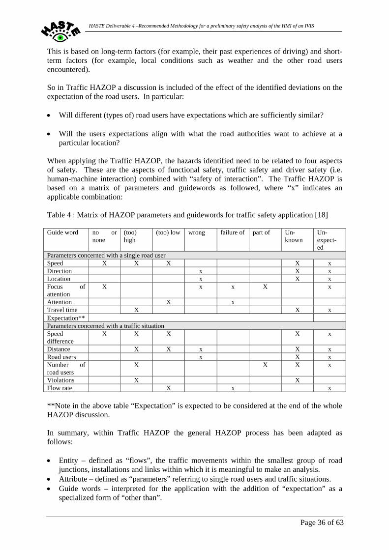
particular location? When applying the Traffic HAZOP, the hazards identified need to be related to four aspects of safety. These are the aspects of functional safety, traffic safety and driver safety (i.e. human-machine interaction) combined with “safety of interaction”. The Traffic HAZOP is based on a matrix of parameters and guidewords as followed, where “x” indicates an applicable combination: Table 4 : Matrix of HAZOP parameters and guidewords for traffic safety application [18] Guide word no or
none (too) high
(too) low wrong failure of part of Un-known
Un-expect-ed
Parameters concerned with a single road user Speed X X X X x Direction x X x Location x X x Focus of attention
X x x X x
Attention X x Travel time X X x Expectation** Parameters concerned with a traffic situation Speed difference
X X X X x
Distance X X x X x Road users x X x Number of road users
X X X x
Violations X X Flow rate X x x **Note in the above table “Expectation” is expected to be considered at the end of the whole HAZOP discussion. In summary, within Traffic HAZOP the general HAZOP process has been adapted as follows: • Entity – defined as “flows”, the traffic movements within the smallest group of road
junctions, installations and links within which it is meaningful to make an analysis. • Attribute – defined as “parameters” referring to single road users and traffic situations. • Guide words – interpreted for the application with the addition of “expectation” as a
specialized form of “other than”.
Page 36 of 63
HASTE Deliverable 4 –Recommended Methodology for a preliminary safety analysis of the HMI of an IVIS
The Traffic HAZOP process shows how the following general principles have to be considered in adapting HAZOP for a new application area: • Careful definition of the entities is required, to ensure that the scope is neither too narrow
(when it may not be possible to make a meaningful analysis) nor too broad (when the analysis may not be specific enough).
• Attributes may have to be derived from piloting the analysis process on known data. • Guidewords have to be interpreted for the application, although it is almost certainly the
case that the generic eleven guidewords will stand scrutiny in any application. However careful descriptions of what the guidewords mean in a particular application context may be required.
• Correct definition of deviations is needed, including the scope of what the analysis
applies to.
6.2 Applying HAZOP to analysis of IVIS
In developing a HAZOP-like process for HMI assessment of IVIS, the following were required to be considered: • Determine which parts of HAZOP are relevant • Determine what is meant by “entity” in this context – early analysis showed a variety of
interpretations. Identify classification of entities – what “information” sets are we largely concerned with? What attributes will need to be considered?
• Consider the Operating envelope for an IVIS evaluation • Develop interpretation of guidewords relevant to IVIS These are discussed in further details below.
6.2.1 Relevant parts of HAZOP Examination of the traditional HAZOP approach showed that the “O” part of the procedure, i.e. that which applied to HAZOP and Operability Tool – Operation (HAZOP-O) were of most relevance to the evaluation of IVIS HMI. This was then used to define an application of HAZOP in this context within HASTE.
Page 37 of 63
HASTE Deliverable 4 –Recommended Methodology for a preliminary safety analysis of the HMI of an IVIS
6.2.2 What are the entities? There are, not surprisingly, a number of different definitions of “entity” in the various standards etc. that refer to HAZOP. • In Def Stan 00-58 [19], reference is made to the system components and the
interconnections between them. The entities are possessed by the components and interconnections but it is not explicitly stated what they are. The implication is that the analyst has to decide on what the entities are based on a model of the system being studied.
• The Yellow Book [20] does not explicitly refer to entities. However the reader is referred
to (amongst others) Def Stan 00-58 for details of the technique. • The draft MISRA Safety Analysis [21] guidelines define an entity as a label associated
with an interconnection between components of a system. It may include interfaces such as signal communications. In practical terms this means that an entity defined in this way will be an information flow.
• Previous work by one of the authors of this document in providing guidance on applying
HAZOP to a specific electronic system defines an entity as the name of a set of data or a signal.
It is therefore proposed that, in the context of the DOP, the following working definition applies:
Entity: an information flow or signal that passes between the IVIS and the driver or other operator. The entity is defined at the system HMI.
Based on this definition, further guidance could then be developed for IVIS HMI application. This could be done most appropriately by taking examples of generic types of IVIS (i.e. categories of systems) to develop the approach and then subsequently apply the technique to actual IVIS products to validate the approach. This process is described in more details in later sections, however some generic entities were initially identified to allow evaluation about how they could be applied for a specific system, along with early assessments on how guidance for the system analyst could be developed. An example is given below.
6.2.2.1 Example A generic entity could be “visual display message”. This might be further decomposed into information messages, modal dialogs, etcetera. Then for a specific system the classes, or even the individual messages, could be identified and analysed. This is illustrated in the figure below.
Page 38 of 63
HASTE Deliverable 4 –Recommended Methodology for a preliminary safety analysis of the HMI of an IVIS
Visual display
message
Generic entity
Information message
Modal dialog
…
Message type
Yes/no dialog
…
Message class
Cancel navigation
(y/n) ?
…
Specific message
Figure 17: Example IVIS classification of entities
In the context of a proposed DOP process for IVIS HMI evaluation this should be applicable at each of these levels of abstraction.
6.2.3 Development of Guidewords A key aspect of the general HAZOP approach is the identification of potential safety and operability problems. This is applied in the context of expert assessors who consider how variability in system behaviour, based upon identified entities and attributes relevant to the system under consideration, maybe influenced by deviations from the intended design behaviour. These deviations are represented by guidewords which act as a stimulation to imaginative analysis by the assessors concerning the impact on that deviation on safety and operability. In the context of each analysis area, or industrial context, in which the HAZOP is applied then assessors evaluate the applicability of “standard” guidewords and make necessary note of the interpretations within that application context. This is also necessary in relation to a HAZOP applied to IVIS HMI and this is considered in further detail later in the process development sections of this deliverable.
6.2.4 Operating envelope One of the perennial problems encountered in safety analysis, particularly when applying the PASSPORT PSA technique, is to define a reasonable (or safe) operating envelope for the system. It is always possible, even if wild imagination is required, to envisage a scenario that would always place the classification of a hazard at the highest level. This is evidently unrealistic.
Page 39 of 63
HASTE Deliverable 4 –Recommended Methodology for a preliminary safety analysis of the HMI of an IVIS
Recent work [21] has identified the need to define a “safe operating envelope” within which vehicles and systems are assumed to be operating. An appropriate “envelope” is to assume that vehicles are being driven with due care and attention, with reasonable consideration for other road users, and are not being driven dangerously, i.e. that drivers are behaving in a manner that conforms to accepted and normal driving practice and standards. “Driven with due care and attention” is the standard of driving that would be expected of a reasonable, prudent and competent driver in all the attendant circumstance, e.g. road layout and geometry, other traffic and road users, weather conditions, and visibility. This is entirely analogous to the way in which hazards are assessed in the aviation industry, where it is assumed that an aircraft is operated within certain constraints, such as the defined operational limitations (both in terms of airframe limitations and aircrew training) and the required maintenance regime. This approach was therefore adopted in subsequent DOP development within HASTE WP4. However it is noted that in the context of a wider Traffic Safety related analysis it is valid to challenge how the “safe operating envelope” may be interpreted if other traffic or road users are not driving with due care and attention and consideration for other road users.
6.3 Interim conclusions
• The general structure for a HAZOP-like process (e.g. DOP) for application to a IVIS HMI
appears to offer potential for a preliminary safety analysis process in line with the HASTE project objectives.
• Consideration is required to identification of some generic entities to enable evaluation of
interpretation of the guidewords in the IVIS HMI context. • Further assessment of the definition of a reasonable operating envelope of an IVIS is
required. On this basis a HAZOP based DOP was developed and this process is described in subsequent sections to this deliverable that took into account the particular application area for an IVIS HMI. This includes a review of the evaluation of the interpretation of the standard guidewords. The need to consider the “reasonable operating envelope” aspect of an IVIS however is required before the DOP can be applied to synthetic or real IVIS concepts. It should be stressed that the discussion described above, and subsequent practical evaluation does not suggest that a standard IVIS defined set of guidewords should be applied. Those described in this deliverable were developed within the multi-disciplinary team engaged in the research to be applicable to the IVIS concepts described. As with other HAZOP applications areas the guide words to be used and their definitions should be examined and developed for the specific application under investigation and by the specific investigators who will apply them. It is also noted that the identification of “entities” within the analysis is also important and in the example given above is based upon understanding the relationships between data and information flow. Further examination of this in practical application of the DOP is shown in later sections.
Page 40 of 63
HASTE Deliverable 4 –Recommended Methodology for a preliminary safety analysis of the HMI of an IVIS
7 Development of a DOP procedure
7.1 DOP applicability within the design process
Earlier sections of this deliverable have identified that an IVIS HMI concept will go through several defined stages from early concept definition to prototype and subsequent manufacture and sale. It is also acknowledged that while design guidelines and regulatory requirements may have an influence on a specific product design, a structured safety analysis procedure is useful for system designers/manufacturers to conduct an early independent system analysis. It is noted that this can potentially yield information to alter the path of development, i.e. addressing design aspects identified as being of concern, and also to add to the development of a safety case for the design concept being pursued. A DOP methodology such as that described above could fulfil that purpose but must be defined in such a way that applicability to the form of product considered here can be shown, and that performing such a procedure can be achieved within an industrial context and that it can yield beneficial results. These aspects are considered in the subsequent sections of this deliverable.
7.2 Assumptions on DOP information requirements
It is clear that in order for a DOP analysis to deliver appropriate levels of relevant detailed analysis of safety and operability issues then adequate levels of system (IVIS) definition should be available to enable that analysis to occur. In previous sections to this deliverable it has been identified that the most appropriate early stage in the development process to administer a formal DOP is when sufficient details have been generated on both the proposed system hardware and the software functionality that supports the IVIS. Ideally this is therefore before further commissioning of later development work to refine hardware and software prior to prototyping. The results of the DOP administered at this stage will identify possible design features of safety concern that should then be addressed in the later development and, if possible, either overcome or alleviated. The DOP therefore requires not only a definition of the general scope for the IVIS (i.e. description of intended application, target market and type of user etcetera) but also a more detailed definition of intended hardware (i.e. form of display, types of controls, installation location etcetera) and a similarly detailed description of software functionality (i.e. outline of system states and state changes, data requirements etcetera). It would also be useful for DOP analysis for the supply of supporting documentation that may include system concept realisations, proposals for, visual display layouts and codings, auditory display characteristics and means of user interaction. It is also suggested that this information would be supplied in an industrial context to an independent “expert group” who would be tasked to administer this safety analysis technique. Further comment will be made on this aspect in later sections.
Page 41 of 63
HASTE Deliverable 4 –Recommended Methodology for a preliminary safety analysis of the HMI of an IVIS
7.3 HASTE DOP Guidewords
An initial preparatory stage in developing the DOP is considering how guidewords for the HASTE DOP can be derived. It has been noted that the DOP is to be derived from the widely applied hazard and operability study (HAZOP). The guidewords applied in the system analysis in this study were initially developed in association with its initial area of application, namely the chemical industry. Application of this approach to other industrial sectors has seen the need to evaluate the use and interpretation of these guidewords in terms most relevant to that sector. An example of this process in relation to Traffic Safety has been given above. In the context of an IVIS HMI evaluation proposed here there is also a need to reconsider the interpretation of guidewords to be applied in this specific context and this interpretation should be evaluated before each practical useage to ensure that the guidewords and their definitions are relevant and applicable to the specific functionality to be evaluated. The standard HAZOP guidewords and their generic meanings have been shown in earlier sections (see Table 2 above). As noted these needed further review in the context of an application within a DOP for IVIS HMI, together with an assessment of the associated interpretations of entities and attributes. In general the entities in a DOP will be data flows or control flows. As a reference point the list of data flows suggested in Table 13.2 of the HAZOP book was taken and initial attempts were made to refine them for the specific application area. This process was carried out by a representative group of experienced system assessors having a wide appreciation of current IVIS characteristics (typical hardware designs, user interface modality concepts and system functionality) as an initial reference model. The results from this process in relation to the applicability and interpretation of guidewords were collected in the form of a summary table of IVIS HMI application guidewords. This is shown in Table 6 overleaf. In this table, the following meanings are attached to “information” and “data” to try to distinguish the shades of meaning in some of the guidewords (e.g. consider the difference between “more” and “as well as” which represent increases that are quantitative and qualitative respectively):
Data = the generic flow Information = the specific flow related to a task or function
Thus “more” meaning “there is additional information transmitted” contrasts with “as well as” meaning “there is additional data transmitted”.
More => I have additional information, but in context As well as => I have additional data, which is out-of-context
Page 42 of 63
HASTE Deliverable 4 –Recommended Methodology for a preliminary safety analysis of the HMI of an IVIS
Table 5 : HASTE DOP guidewords Generic guideword
Flow (of data or control) – machine
Flow (of data or control) – human
Data to/from data store (machine)
Data to/from human memory
No The information is not transmitted
The human cannot receive and/or understand the request or cannot establish communication
The information is not stored or recalled at all
Information not stored or forgotten
More There is additional information transmitted
The human understands or communicates more than is intended or necessary
The system stores or recalls additional information
The human stores or recalls additional information
Less The information transmitted is not complete
The human understands or communicates less than is intended or necessary
The system does not store or recall all of the information
The human does not store or recall all of the information
As well as There is additional data transmitted
The human understands or communicates additional data
The system stores or recalls additional data
The human stores or recalls additional data
Part of The data transmitted is not complete
The human understands or communicates only part of the data
The system does not store or recall all of the data
The human does not store or recall all of the data
Reverse The opposite information to the intention is transmitted
The human understands or communicates the opposite of what was intended
The system stores or recalls the opposite of what was intended
The human stores or recalls the opposite of what was intended
Other than Completely different information is transmitted
The human misunderstands the request or gives the wrong reply
The system stores or recalls completely different information from what was intended
The human stores or recalls completely different information from what was intended
Early The information is transmitted before the intended time
The human “jumps to conclusions” and gives an inappropriate response
The system stores or recalls the information before the recipient is ready
The human “jumps to conclusions” and gives an inappropriate response
Late The information is transmitted after the intended time
The human does not understand or communicate the information early enough
The system does not store or recall the information quickly enough
The human does not store or recall the information quickly enough
Before The information is transmitted before the intended place in sequence
The human understands or communicates the information in an incorrect order
The system stores or recalls information in an incorrect order
The human stores or recalls information in an incorrect order
After The information is transmitted after the intended place in sequence
The human understands or communicates the information in an incorrect order
The system stores or recalls information in an incorrect order
The human stores or recalls information in an incorrect order
Page 43 of 63
HASTE Deliverable 4 –Recommended Methodology for a preliminary safety analysis of the HMI of an IVIS
7.4 Initial Review of DOP application
These amended guideword interpretations were then applied to an evaluation of a generic IVIS application to practically review the proposed process. In order for this to be achieved a concept system was defined based upon existing IVIS product functionality. The concept system was selected to enable a “simple” IVIS interaction to be assessed and to enable the verification of the definitions of attributes, entities and guidewords discussed above. The IVIS functionality chosen was based upon a category of current market IVIS devices that are retrofit devices that provide drivers with a simple warnings based upon proximity to a speed camera enforcement sites. A variety of models are currently available in some European markets, from a number of individual suppliers, which offer this functionality. However while detailed design differences exist, they all have similar functionality and types of operation. Therefore a synthetic product specification and functionality definition was constructed for a typical IVIS of this kind based upon a working knowledge of this form of IVIS. An illustration of one of these types of simple IVIS devices is given below.
Figure 18 : A Speed Camera Enforcement Site Warning Device (Cyclops UK)
7.4.1 Concept System Definition The concept system is a speed limit warning device. This is a very simple IVIS that contains an internal database of speed limits. The system uses GPS to determine the vehicle’s location and speed, and warns the driver if the local speed limit is being exceeded, in particular when approaching a speed camera enforcement site. When the driver is not exceeding the speed limit, the system may be set to display either the heading on which the vehicle is travelling, or the speed the vehicle at which the vehicle is currently travelling. This type of IVIS was defined for the purposes of this analysis by the production of an outline product specification. This was supported by the development of a state change diagram that defined the operating functionality typical of the real products of this kind. Finally a data flow diagram was constructed that represented the IVIS and therefore enabled analysis within the DOP. It was therefore assumed that the design of the system had progressed to the point at which the concept has been defined and the following supporting documentation would be available:
Page 44 of 63
HASTE Deliverable 4 –Recommended Methodology for a preliminary safety analysis of the HMI of an IVIS
• A Concept definition – that defined what was intended to be the overall functionality of the system and other scoping information (e.g. type of display/HMI, target performance, range of application etcetera). This would be detailed in the outline product specification noted above.
• Functional model of how the system will behave. This would be detailed by the state
change and data flow diagrams noted above. In an industrial context this would represent a starting point for a design team is to start hardware and software development in order to realize the system. It is therefore an appropriate stage for a preliminary analysis to be carried out. Some further considerations on the use and applicability of such a functional model in specific relation to the IVIS concept described above is given below.
7.4.2 Functional model – Concept IVIS There are a number of functional representations available, but we assume that the designers have chosen to use a state-chart representation. Such a representation is fairly common for HMI design, as it allows the transitions between various states of the system to be represented easily. A simplified state chart for the system is shown below (Figure 19), where the circles are the states and the lines are transitions between the states. The line labels show the event that must occur to trigger the transition. There is assumed to be a calibratable hysteresis for the over limit and under limit transitions to prevent the system “hunting” if the vehicle speed is fluctuating around a limit. It should also be noted that in the state chart a number of the transitions have been omitted for clarity, including: • Transitions from any state to “system off” (i.e. power down) • Transitions from and to any state back to the “acquire location” state, such as may be
experienced if insufficient satellites are visible for an accurate GPS fix • The system behaviour during an update of the speed limit database • Any progression in the alert stages (e.g. different tones at given levels or given
percentages above the limit e.g. L+10, L+20, … or L+5%, L+10%, …) Note that the state chart is more amenable to representing “object oriented” types of functions (such as those associated with an interactive application) than procedural functions. Examples of procedural functions would be the algorithm that calculates the vehicle’s position as latitude and longitude from the raw GPS signal, and the algorithm that calculates the vehicle’s heading and speed based on successive location data.
Page 45 of 63
HASTE Deliverable 4 –Recommended Methodology for a preliminary safety analysis of the HMI of an IVIS
Page 46 of 63
Switch On
AcquireLocation
Power OnLocationAcquired
DisplayHeading
Mode :=Speed
DisplayAlert
DisplaySpeed
V < (L+h2)
Mode :=Heading
V > (L+h1)V > (L+h1)
V < (L+h2)
Machinetask
On-TripHMI
Pre-TripHMI
V : Vehicle SpeedL : Speed Limith : hysteresis
Figure 19: State chart for the speed limit warning system In addition, to perform the DOP, a representation of the data flows in the system is required. This may have been produced as part of the design, or it may need to be produced (or augmented) for this analysis. An example of a data flow diagram is shown in the figure overleaf (Figure 20). It should also be noted that the diagram distinguishes between machine-related tasks and data flows, and human-related tasks and data flows.
HASTE Deliverable 4 –Recommended Methodology for a preliminary safety analysis of the HMI of an IVIS
Page 47 of 63
Determinex , v
GPS Data
SpeedLimit
Database
x , v
CentralDatabase
DisplayDefault
DetermineLocal Limit
DisplayData
ChangeSettings
AcquireData
InterpretData
Performdrivingtask
Vehicleheading
VehicleProperties
Traffic andAmbient
Conditions
InfrastructureEnvironment
Speedlimit alert
Figure 20: Data flow diagram for speed limit warning system
On-TripDriverTask
Pre-TripDriverTask
Machinetask
HASTE Deliverable 4 –Recommended Methodology for a preliminary safety analysis of the HMI of an IVIS
These diagrams have identified the functionality of the IVIS, and it was assumed that the assessors would be aware of the interaction modalities (e.g. visual and auditory displays) and IVIS control operational characteristics (e.g. controls design). It was then necessary to carry out an identification of items to analyse in a DOP. The entities have been defined earlier and the attributes are classified as, Value – the numerical or textual or other content of the data flow, Time – the relative time in which the data flow occurs and Sequence – the sequence or order related to the data flow (e.g. the speed limit alert may have several stages which are supposed to occur in a pre-defined order). Table 6 : Speed Camera warning Device - Concept IVIS - Data Flows and attributes Data flow name From To Attributes Vehicle heading System Display Value, time Vehicle speed System Display Value, time Speed limit alert System Display Value, time, sequence No GPS warning System Display Vehicle heading Display Human Vehicle speed Display Human Speed limit alert Display Human No GPS warning Display Human Change mode to heading Human System Change mode to speed Human System The concept IVIS data flows were then assessed by the expert assessor group utilising the refined guidewords defined in earlier sections. The results from this assessment were then summarised in a table. This is shown below in Table 7 Table 7 : DOP analysis of concept IVIS Entity Attribute Guide
word Interpretation Cause Consequence Recommendation
Vehicle heading
Value No The vehicle heading is not displayed
Internal error
Customer satisfaction only
Speed limit alert
Value More The speed limit displayed in the warning is higher than the prevailing limit
Database incorrect
The driver may be inclined to exceed the speed limit if they are ignoring other cues
Sequence Before The system does not “count down” the approach to a changing speed limit and the final warning is displayed first
Poor GPS reception leading to late recognition
The driver may make a sudden reaction to the late warning
Page 48 of 63
HASTE Deliverable 4 –Recommended Methodology for a preliminary safety analysis of the HMI of an IVIS
7.5 Application of Procedure
This initial evaluation of the outline DOP approach identified several potential safety/risk consequences as a result of possible system functionality and driver reaction. These were broadly in line with what would be expected for the generic IVIS hypothetically assessed above. It should be noted that the “recommendation” column in table 7 above was deliberately included as it would form an important part of the process if applied in a real-life industrial product assessment context. Aspects of IVIS design that gave rise to concerns, based upon a DOP analysis, should also offer practical recommendations to the IVIS designers as to how potential remedial measures may be applied in later development. In this example case however this aspect remained uncompleted. It was also noted that the depth of the analysis carried out here was dependant both upon the level of details available on system design and functionality, and the level of knowledge amongst the expert group in carrying out the approach. This level of knowledge applied as much to familiarity with the broad application of safety assessment procedures (experience) and also of the technical basis for delivery of the specific IVIS functionality (technical). As part of this assessment of the outline DOP method was focussed on not only what the DOP could provide, but also on the way in which it should be administered, these are important factors. These will be considered in later sections. It may therefore be expected that in a real industrial application of a DOP that a larger number of potential problems may be developed when a much fuller detailed concept description is available. The example given above may therefore be seen as a simplification of a typical application of the DOP which has, by necessity, been carried out external to a formal product specification and development process. It is also necessary to consider that in the real-world application of a HAZOP related DOP within a safety assessment process that all identified problems are important to be noted and considered within the safety case documentation.
7.6 Interim Conclusions
The HAZOP based DOP utilising a an amended set of guidewords for an IVIS application was used on a generic IVIS functionality synthesised from a range of current market product. Even with limited “concept definition” and system functionality documentation, the DOP approach offered meaningful results concerning aspects of IVIS use that could potentially generate inappropriate and potentially risky user (driver) behaviour. The use of an “expert group” was considered a vital part to the success of the process. In this case a three man team having backgrounds in computer software design, electronic systems design and evaluation and human factors engineering were chosen. These individuals also had considerable experience of carrying out ITS and IVIS concept and safety assessments. The application of such a DOP will depend upon having such a group to support the analysis and identify actions/recommendations. To further investigate the use of a DOP for IVIS HMI assessment, a further validation process was then required. This should utilise a real-world IVIS that had been assessed by other external evaluation methodologies studying the potential, or actual, operation by drivers while driving to enable results to be compared.
Page 49 of 63
HASTE Deliverable 4 –Recommended Methodology for a preliminary safety analysis of the HMI of an IVIS
8 Validation of DOP The next stage in the development of a DOP within HASTE was intended to validate the approach by comparing the results from a DOP analysis to that of other assessment methodologies. In order to do this a real-world IVIS was selected that had been evaluated in practical trials in other parts of the HASTE project, and hence where HASTE protocol results were available for comparison.
8.1 Selection of IVIS
Out of the range of IVIS devices evaluated in HASTE WP3 [4] a single IVIS was selected. This was a route navigation function that was mounted on a PDA platform for portability. This is illustrated in the Figure below.
Figure 21 – PDA Based Navigation IVIS
This device enabled most current “standard” route navigation functions. It offered turn-by-turn guidance by both visual and auditory (voice) display with a range of driver selectable display options. The device was selected for further DOP evaluation as it offered easily defined functionality and operational capability in the geographical region it was evaluated and also represented perhaps the most common IVIS functionality currently on the market in Europe.
Page 50 of 63
HASTE Deliverable 4 –Recommended Methodology for a preliminary safety analysis of the HMI of an IVIS
8.2 DOP application – Expert Group
The application of the DOP to the PDA based Navigation IVIS described above was performed by the same three man team that had performed the initial development of the DOP procedure and had carried out the evaluation of the earlier generic IVIS. Once again this provided an appropriately experienced group for this sort of evaluation method.
8.3 DOP application – Validation
In a similar manner to the approach used for the speed limit warning device (see section 7 above) an initial state change diagram was constructed that followed the perceived operating behaviour of the device complete with the route navigation function. This is illustrated in the figure below.
AcceptWarning?
Initialising
WarningAccepted
CurrentMap
Done
Set Prefer-ences
MenuSet
Destin-ation Entry
Menu
Show
AcquireGPS
Go CalculateRoute
GotGPS
DisplayCurrentPosition
RouteFound
AnnounceArrival
DisplayAlternative
Data
SelectDisplay × N
“In Nyards turn
L/R”
“Prepareto exit L/R”
“Turn L/R”
DestinationReached Dual Carriageway
& 1 mile from exit
N yardsfromexit
Close to exit
CalculateSeverity
Get backon route
Minor
Major Minorchanges
Off route
Machinetask
Pre-TripHMI
On-TripHMI
Figure 22 – State Change Diagram PDA based Navigation IVIS Following this stage a data flow diagram was then constructed by the expert group and the data flows were evaluated using the amended interpretations of the HAZOP/DOP guidewords. The figure shown below illustrates the data flows for the selected real world IVIS function.
Page 51 of 63
HASTE Deliverable 4 –Recommended Methodology for a preliminary safety analysis of the HMI of an IVIS
Determinex , v
GPS Data
Map
x , v
CD-ROM
RouteCalculateRoute
SetDestin-ation
DetermineInform-ation
DetermineLocation
DetermineGuidance
DisplayLocation
DisplayInformation
DisplayGuidance
Set Prefer-ences
SelectInform-ation
AcquireData
InterpretData
Performdriving
task
Traffic andAmbient
Conditions
InfrastructureEnvironment
VehicleProperties
Pre-TripDriverTask
On-TripDriverTask
Machinetask
Figure 23 : Data Flow Diagram PDA based Navigation IVIS
8.4 Issues Identified
The application of the guide words, and the review carried out by the expert group, within the HASTE DOP is tabulated below.
Page 52 of 63
HASTE Deliverable 4 –Recommended Methodology for a preliminary safety analysis of the HMI of an IVIS
Table 8 : DOP applied to PDA based Navigation IVIS Entity Attribute Guide
word Interpretation Cause Consequence Recommendation
IVIS display
General image
Less Driver doesn’t (can’t) see display
Ambient lighting conditions
Inappropriate driver reaction
Design – shading/contrast protection
Local map Graphic image
Less Not enough info
Inappropriate scale
Inadequate guidance Distraction
Ensure functionality has appropriate default
Local map Graphic image
More Too much info
Ditto Ditto Ditto
Local map Graphic image
Less No relevant info
Map out of date or off map
Ditto Ensure functionality has appropriate default
IVIS display
General image
More Display too bright for ambient conditions
Backlight too bright for ambient conditions
Distraction and glare
Implement day/night or background lighting options
IVIS display
General image
Other than
Display interruption by another application
e.g. diary reminder pops up
Temporary loss of IVIS function
IVIS function should be capable of being set as the priority application
Ditto Ditto Ditto Ditto Ditto Requires additional interaction with interface to cancel and return
Ditto
Local map Graphic image
Late Map scale does not change in time
e.g. delay in GPS position update
Inadequate guidance Distraction
Ensure functionality has appropriate default
Turn instruction
Auditory message
No Driver does not receive message
Low signal level compared to ambient conditions
Driver not advised of imminent turning
1. If possible, control the volume of IVIS 2. If base device not loud enough provide additional amplification
Turn instruction
Auditory message
More Instruction to take turn when there is no turn to take
Incorrect interpretation of mapped links
Driver could be confused and/or distracted
Ensure navigation algorithm is robust
Turn instruction
Auditory message
Less No instruction to take turn when there is potentially a turn to take
Incorrect interpretation of mapped links
Driver could be confused and/or distracted
Ensure navigation algorithm is robust
Turn instruction
Auditory message
Other than
Message interruption by another application
e.g. diary reminder interrupts
Temporary loss of IVIS function
IVIS function should be capable of being set as the priority application
Turn instruction
Auditory message
Late Message is not given in time
e.g. delay in GPS position update
Inadequate guidance Distraction
Use map image as backup
Page 53 of 63
HASTE Deliverable 4 –Recommended Methodology for a preliminary safety analysis of the HMI of an IVIS
8.5 Analysis of application of DOP
The DOP once more provided a suitable framework for IVIS based HMI evaluation based upon the level of detail available on system design and functionality, and on the knowledge of the expert group. Clearly this was an artificial application of the DOP as the products specifications etcetera were in fact derived from a mass-market product and not, as would be the most likely scenario, early system definition details from a design team prior to initial prototyping. However it is thought that the synthesis of the state change and data flow diagrams, supported by other concept definition details, were an appropriate representation of what could exist in an industrial context. It was also found that carrying out the process of developing the necessary system definition information and diagrams and applying the DOP evaluations using the guidewords, and tabulating the results and recommendations took between 1 and 2 working days. The completion of the process within such a timeframe would of course be dependant upon many factors. This would include the level of concept detail available, the familiarity of the expert group with the process, the complexity of the IVIS to be assessed and the desired manner in which conclusions were to be recorded and recommendations made. However in general terms the process was enabled to be carried out in a manner of days rather than weeks and is therefore more amenable to the demands within industry for cost-effective product assessment methodologies, although will need further investigation.
8.6 Comparison with other evaluations
It was noted that this selected IVIS function had also been selected to allow comparison of the DOP results, intended for a pre-prototype stage application in industry, with other evaluation methods. These other methods may be more suited to other stages in the product lifecycle.
8.6.1 Evaluations within HASTE WP3 The use of alternative methods of evaluating real-world IVIS products had been investigated in HASTE D3 [4]. This had included comparing the evaluation results from both the design checklists and the full HASTE experimental protocol employed in the trials described in that deliverable. In this earlier HASTE work the PDA based Navigation IVIS was described as System B. This terminology is used in the remaining parts of this section. A synthesis of the description of the process carried out, and the results comparison described in this earlier deliverable, is given below.
8.6.2 TRL checklist One such alternative evaluation method proposed that may be carried out at an early stage in the design process is the application of the TRL checklist [23]. This assessment approach parallels the statements made in the European Statement of Principles and attempts to translate them into verifiable design parameters which may be administered as a checklist of “acceptable” design aspects of an IVIS.
Page 54 of 63
HASTE Deliverable 4 –Recommended Methodology for a preliminary safety analysis of the HMI of an IVIS
The TRL Checklist consists of six major categories on which a system is to be evaluated by an expert: • Documentation • Installation and integration • Driver input controls • Auditory properties • Visual properties of display and display screen • Dialogue between user and system This is very similar to the categorization utilised in the European Statement of Principles. The ‘Dialogue’ category also has a subcategory that refers to the ‘Safety-related aspects of information.’ All other safety-related aspects are assumed to be implicit within the aspects judged in each category, which perhaps may traditionally have been classified as ‘usability’ aspects.
8.6.3 Procedure In HASTE WP3 the TRL checklist was completed for every IVIS being evaluated by the experimenter who had been using that system in the HASTE (WP3) experimental trials. Therefore the evaluator was familiar with the operation of the IVIS. Two of the HASTE partners carried out the evaluation on System B, Volvo Technology (VTEC) and TNO Human Factors (TNO)
8.6.4 Results The results of the TRL checklist assessment was then summarised for each assessment performed, and an assessment given as whether the checklist findings could be linked to the HASTE experimental results.
8.6.4.1 System B - Summary for VTEC
Serious Concerns / reasons
• The only possible position for the IVIS (due to the suction cup solution) is a really poor ergonomic solution. It also obstructs the vision ahead.
• Usage of the “pen” means difficulties to interact with the system; the graphic demands high precision and the pen means that one hand is occupied in an emergency situation.
• The auditory feedback (turn directions) is barely audible, which instead makes visual attention to the display important.
• System response time creates confusion. It is too long and makes the user wonder if he/she even succeeded to point at the right spot in the graphical interface. This requires great visual attention.
• Menus are accessible during driving which may affect attention to the road. Minor Concerns / reasons
• The size of the display is a little small to display complex maps. • The attaching device is not stable enough on uneven surfaces. • The physical controls do not communicate their function clearly enough (legibility of
symbols is poor), and feedback on activation is not clear enough.
Page 55 of 63
HASTE Deliverable 4 –Recommended Methodology for a preliminary safety analysis of the HMI of an IVIS
Overall Assessment The instruction says that the system should not be operated during driving. However, since it is possible to use it during driving, drivers will probably do so, hence the concerns above. The system is consistent with current standards, which is good. But it is still not good enough to be used during driving (i.e. to interact with during driving).
8.6.4.2 System B - Summary for TNO
Serious concerns / reasons First it should be stressed that the supplier of B clearly states not to operate the system while driving. Therefore, it assumes that drivers plan their route before they start driving and these were therefore excluded from evaluation. However, it was noted that while driving there are few options that the driver can use, e.g. zooming in and out or changing the way the direction is indicated. This is done by pressing a small button under the screen. This button is clearly located but is too small to be used for different options. An example of this is that by pressing the left side of the button the driver could go to the menu. However, he should never get there while driving because the only way out is by pressing a small icon with the stylus. Pressing the same button at the top or bottom allows zooming in or out of the display, while pressing the right side of the button changes the manner in which the direction indication to the driver is given. The auditory output is far too low (in output). However, the auditory direction indications are very useful. The system does not react very quickly when zooming in and out. Minor Concerns / reasons Colour coding can be (much) better Overall assessment Nice PDA and route guidance looks rather nice. However, in its present form it should not be used in the car unless there is a passenger to operate the system while driving. The volume level is too low and the control for zooming in and out may lead to too many errors. Additional comments It should be stressed once more that only the controls that may be used while driving were examined. Of course there are other features like entering a destination. If we assume that it is normal for a driver to enter a destination while driving I think it will be clear that this system (or any other system that needs visual guidance to select information) is unsuitable. Another problem with the present system is that it is not a dedicated route guidance system and, therefore, offers too many functions while driving.
Page 56 of 63
HASTE Deliverable 4 –Recommended Methodology for a preliminary safety analysis of the HMI of an IVIS
Recommendations The control for adjusting the zoom level of the direction indicator must be adjusted. These should be separated to avoid errors. The volume level should be increased. The route guidance system is GPS-based and therefore it detects movement. If so the software might be programmed such as to exclude the possibility of using unwanted functions while driving.
8.6.5 Comparison with HASTE experimental results It should be noted that HASTE WP3 considered four real world IVIS products. These were noted as systems A, B, C and D. All had the TRL checklist applied to them and all were evaluated in subject trials using the full HASTE protocol. The following comments were made about the systems in HASTE D3. The checklist assessment yields judgements that are naturally qualitative. For that reason alone they are hard to compare with the quantitative results of the HASTE studies. On the other hand, the checklist judgments may lead to conclusions – on the criticality of driving with the system, in particular – that can be compared to those one would reach on the basis of quantitative statements. If we look for such ‘strong’ statements in the summaries given above we find the following: System B is explicitly condemned by one assessor as not being usable while driving. Thus, a rank ordering of systems in terms of being fit for use while driving, perhaps in terms of a simple pass-fail criterion, would possibly look as follows: Systems B and D are worst, followed closely by System A. System C is relatively acceptable. Thus the ordering would be (B,D); (A); (C). The rank ordering of systems on the basis of the HASTE experiments, was roughly as follows: (B); (D); (A); (C). Although there are all kinds of difficulties associated with comparing such wildly different and ordinal assessment dimensions, it appears that the two rank orders are quite similar, i.e. not blatantly dissimilar.
8.7 Discussion
The comparison between the HASTE experimental results, and the TRL checklist results, in WP3 were based on rough blocks of material, each of them summarizing a detailed body of measurements, expert ratings, specifications, etcetera. Therefore, the comparison of results must be taken with more caution than is already usual in this type of research. However, the results of the comparison are encouraging at what might be called the zero-order level. The result may then point the way to an approach in which checklists and behavioural measurement procedures are seen as complementing each other. As such discrimination between systems assessed here showed a similar ranking order between TRL checklist and experimental results although more complex order effects are not so clear.
Page 57 of 63
HASTE Deliverable 4 –Recommended Methodology for a preliminary safety analysis of the HMI of an IVIS
In comparison the TRL checklists results in WP3 and the DOP results in WP4 were also assessed. These of course related to one IVIS (System B) only. This analysis of potential hazards for system B from the DOP assessment was therefore compared with the results generated by the application of the TRL checklists in WP3. This indicated that they both identified concerns with the auditory output audibility, system response time and display size (and therefore legibility). However the TRL checklist identified specific input functionality and display location and rigidity issues that were not specifically noted in the DOP assessment. However it should be noted that, at a concept/pre-prototype stage of development, not all such design aspects may be defined and/or known. The DOP did however identify issues that the TRL checklist did not. These related to factors such as possible deterioration of the display due to ambient lighting conditions and IVIS function priority that the checklist did not identify. The two approaches are of course based upon slightly different bases. The checklist is intended to act as an indicator of whether an IVIS complies with good design practice guidelines. The DOP however is based upon an examination of where impaired IVIS performance in interacting with a human operator (driver) may lead to hazardous or impaired performance outcomes. The full HASTE experimental protocol however seeks to fully examine the interaction of the driver with the IVIS while driving an estimate the relative impact of the tasks introduced by the IVIS on driving performance.
8.8 DOP Validation - Implications
The validation exercise carried out utilising the DOP for an assessment of a real-world IVIS (System B) has provided some interesting results. The DOP, with the interpretation of the standards HAZOP guidewords for applicability to an IVIS, once more yielded a useful indicator of areas of design concern. These in turn could be used as a basis for analysis of possible design recommendations to improve system usability and reduce risk. The DOP application within the validation study described above also was performed over a 1-2 day period once more therefore suggesting that it could provide a cost effective system assessment tool within industry if supported by appropriate IVIS functionality and concept definitions, and carried out by appropriately experienced “expert group”. The comparison of results between the DOP and the TRL checklist, and the HASTE experimental trial results also highlighted some points of interest. All three techniques offered useful systems assessment. The full HASTE protocol offered the most comprehensive and robust assessment of the impact of an individual IVIS, and relative merits of different IVIS, on driving performance. However the DOP and checklist approach are intended to be applied at a pre-prototype stage of IVIS development when execution of the full experimental protocol is not feasible. The DOP is intended to be applied to guide IVIS design by highlighting areas of design concern, and
Page 58 of 63
HASTE Deliverable 4 –Recommended Methodology for a preliminary safety analysis of the HMI of an IVIS
establishment of recommendations to refine the operability of an IVIS. This has been demonstrated as a workable approach within the DOP development and validation process described above. The early concept assessment tools (checklist and DOP) appear to offer complimentary analysis of the appropriate nature of an IVIS functionality and design. There therefore seems to be a place for both assessment tools, or perhaps a some future hybrid version incorporating elements of both, for application within appropriate stages of the industrial product lifecycle.
Page 59 of 63
HASTE Deliverable 4 –Recommended Methodology for a preliminary safety analysis of the HMI of an IVIS
9 Conclusions The application of a HAZOP derived DOP to an IVIS therefore seems to be a useful assessment methodology to investigate the potential risks to a proposed IVIS HMI at an early stage in product development. The use of the DOP in association with a Preliminary Safety Assessment is also encouraged to develop a Safety Case for a new IVIS product. It will also assist in the identification of design issues that will need subsequent attention and re-evaluation as the design process proceeds prior to eventual assessment using a full HASTE experimental protocol. The context within which a DOP should be used is therefore as a design audit tool within the overall industrial product design and development lifecycle. The earlier figure showing the intended positioning of the DOP within a generic product lifecycle (Figure 13) has indicated where conceptually this may most beneficially apply. This “pre-prototype” stage enables an IVIS to be assessed, and HMI design concerns to be identified, prior to finalising decisions being made in an IVIS concept evolution from earliest product ideas to manufacture and sale. It is also important that such a DOP is embedded into a defined safety lifecycle within an industrial company. The DOP in this sense becomes an integrated part of delivering a safety case for a product. It is not therefore seen to be an additional assessment burden, but rather a formalised way of early assessment of complex driver/IVIS interaction issues. Earlier diagrammatic representations of the product lifecycles from automotive and automotive electronics industries have shown potentially that there are different interpretations as to what constitutes the elements within the design and development process and what those elements are called. It should therefore b appropriate to suggest that the DOP should be defined as an element within a safety and product assessment framework. This can then be adopted to the individual needs and organisational structures and working procedures of each industrial company, rather than as a prescriptive process. The setting within which a DOP is performed, guided and recorded is also a relevant issue within an industrial context. The need for an independent set of system assessors from within the industrial company to perform system audits such as the DOP is highlighted. The need for appropriate skills has also been noted in earlier discussions. It has not been possible to explore this skills issue in detail within this project. However it seems clear that if a DOP is to be performed to evaluate impartially the HMI of an IVIS that may be used by a driver while driving, and that may therefore have some negative impact on driving, then appropriate skills and experience are required by the assessors. These include a knowledge of human factors engineering/driver behaviour, computer software and electronic system design, the specific IVIS application area and technologies and (potentially) vehicle engineering. Equally important is the need for skilled assessors briefed on the use of such a system assessment approach. In an industrial context it may be feasible to have specialised and trained system assessment teams. Experience and skills in this area are a more appropriate base for the delivery of more comprehensive system analysis and hopefully have an impact on the quality of issue identification and recommendations. This should be seen as a longer term benefit to “getting the design right” with subsequent beneficial impacts to commercial deployment of the IVIS. The evaluation of the guidewords for specific applicability to a defined IVIS is also an important factor in the process of applying a DOP.
Page 60 of 63
HASTE Deliverable 4 –Recommended Methodology for a preliminary safety analysis of the HMI of an IVIS
The definition of guidewords and their interpretation, and that of identified IVIS entities is also an important responsibility of the DOP assessment team and has been highlighted above. Further consideration of how other aspects of system safety processes within the overall evaluation of a product to be used in a vehicle while driving may also need to be considered beyond the DOP. These may include more detailed considerations of fault conditions and impacts to traffic safety, and may also need to consider later stages in the product/system lifecycle such as operation and decommissioning that have not been specifically considered here. These aspects may therefore fill in analyses from different development stages that would complement the early DOP in an overall system analysis. The application of the DOP is therefore an important pre-cursor to possible further internal or independent (third party) application of a later product assessment evaluation such as the full HASTE experimental protocol. The actual mechanics of the HASTE recommended DOP process in earlier sections, however in conclusion it may be suggested that the DOP process has to be used within an industrial design context and must therefore be capable of delivered in that environment. This may require an overall industrial take up of the following action areas : • The identification of the need to carry out a DOP on a new concept IVIS HMI within the
context of a design lifecycle and manufacturing industry • The identification of roles and responsibilities, and timing, to carry out the DOP • The identification of roles and responsibilities, and timing, to react to recommendations
from the DOP • The supply of IVIS concept definition material to an independent DOP evaluation team
“expert group”, e.g. functional specifications, concept definitions, proposed hardware design and application information, state change and data flow diagrams
• The need for the DOP evaluation team to consider and define guidewords, entities and other relevant factors within the context of a specific IVIS application
• The supply of resources (training, skills etcetera) to the members of the “expert group” • The supply of HASTE defined IVIS oriented guidewords to enable the DOP to be performed • The application of the DOP and formation of recommendations • The identification of an iterative inspection/checking process to ensure that the
recommendations have been subsequently acted upon • The overall contribution of the DOP to the construction of a specific IVIS safety case. It is hoped that subsequent work will enable this DOP methodology to be assessed for industrial acceptability, robustness across varied IVIS applications, cost-effectiveness and conceptual incorporation within safety case procedures. This will therefore require both wide consultation with manufacturing industry and safety engineering and future research providers in relation to driver performance, safety and risk estimation.
Page 61 of 63
HASTE Deliverable 4 –Recommended Methodology for a preliminary safety analysis of the HMI of an IVIS
10 References [1] European Statement of Principles, European Statement of Principles for in-vehicle
information and communication systems, Adopted by the European Parliament 21st December 1999
[2] A J Roskam et al, Development of Experimental Protocol, HASTE Deliverable 1 v1.0 July
2002 [3] J Ostlund et al, HMI and Safety-Related Driver Performance, HASTE Deliverable 2 v1.3,
August 2004 [4] E Johansson et al, Validation of the HASTE protocol specification, HASTE Deliverable 3
v1.0, April 2005 [5] O M J Carsten, HASTE Final Report, HASTE Deliverable 6 v1.0, May 2005 [6] J Giezen, P Jesty and M Fowkes, Identification of Safety Hazards and risk analysis for the
HMI of automotive systems and IVIS, HASTE Internal Report 4.1 v1.2 [7] E N Mazzae, W R Garrott, F S Barrickman and T A Ranney, Device related distraction
measurement : Preliminary Findings and Research Challenges, NHTSA Driver Distraction Forum, May 2001
[8] T Heijer et al, Problem Identification and Actor Classification, ADVISORS Deliverable
D1/2.1 v12, February 2003 [9] UN ECE Regulation 13 Annex 18 “Complex Electronic Systems” [10] IEC 61508, Functional Safety of Electrical/Electronic/Programmable Electronic Safety-
Related Systems, International Electrotechnical Commission, 1998–2000. [11] UTMC22, Framework for the Development and Assessment of Safety-Related Urban Traffic
Management and Control Systems, Department of the Environment, Transport and the Regions, 2000. (www.utmc.dtlr.gov.uk/utmc22/pdf/utmc22-framework.pdf).
[12] DRIVE Safely, Towards a European Standard: The Development of Safe Road Transport
Informatic Systems, 1992. [13] K M Hobley et al., Framework for Prospective System Safety Analysis Volume 1 —
Preliminary Safety Analysis, Deliverable N° 9a, V2058 PASSPORT project of the Advanced Transport Telematics (ATT/DRIVE II) sector of the TELEMATICS APPLICATIONS Programme, Third Framework Programme (1991–94), 1995.
[14] Development Guidelines for Vehicle Based Software, MIRA, CV10 0TU, 1994, ISBN 0-
HASTE Deliverable 4 –Recommended Methodology for a preliminary safety analysis of the HMI of an IVIS
[15] Becker et al, The integrated approach of User, System and Legal Perspective : Final Report on Recommendations for testing and market introduction of ADAS. RESPONSE Project Deliverable D2.2 September 2001. CEC DG XIII.
[16] EASIS Project, Deliverable D0.1.2, State of the art, August 2004. [17] HAZOP Ref F Redmill, M Chudleigh, and J Catmur, System Safety: HAZOP and Software
HAZOP, John Wiley and Sons, 1999, ISBN 0-471-98280-6. [18] H M Jagtman, Road Safety by Design – A decision support tool for identifying ex ante
evaluation issues of road safety measures, Eburon – Delft 2004, ISBN 90-5972-045-8 [19] Def Stan 00-58, HAZOP studies on systems containing programmable electronics, Issue 2,
2000. [20] The “Yellow Book”, Engineering Safety Management – Volumes 1 and 2, Fundamentals
and Guidance, Issue 3, Railtrack, 2000. [21] MISRA, Guidelines for the Safety Analysis of Vehicle Based Programmable Systems, Draft
Version 7, August 2004. [22] MISRA Technical Report, Hazard Classification for Moving Vehicle Hazards –
Controllability, May 2004. [23] A Stevens et al, A Safety Checklist for the assessment of In-Vehicle Information Systems :
Scoring Proforma, TRL Project Report PA3536-A/99, December 1999