Bruce L. Tai Andrew J. Jessop David A. Stephenson Albert J. Shih Department of Mechanical Engineering, University of Michigan, Ann Arbor, MI 48109 Workpiece Thermal Distortion in Minimum Quantity Lubrication Deep Hole Drilling—Finite Element Modeling and Experimental Validation This paper presents the three dimensional (3-D) finite element analysis (FEA) to predict the workpiece thermal distortion in drilling multiple deep-holes under minimum quantity lubrication (MQL) condition. Heat sources on the drilling hole bottom surface (HBS) and hole wall surface (HWS) are first determined by the inverse heat transfer method. A 3-D heat carrier consisting of shell elements to carry the HWS heat flux and solid elements to carry the HBS heat flux has been developed to conduct the heat to the workpiece during the drilling simulation. A thermal–elastic coupled FEA was applied to calculate the workpiece thermal distortion based on the temperature distribution. The concept of the heat carrier was validated by comparing the temperature calculation with an existing 2-D advection model. The 3-D thermal distortion was validated experimentally on an aluminum workpiece with four deep-holes drilled sequentially. The measured distortion on the reference point was 61 lm, which matches within uncertainty the FEA predicted distortion of 51 lm. [DOI: 10.1115/1.4005432] 1 Introduction Workpiece thermal distortion is critical to the part dimensional accuracy and quality control in precision machining processes. The distortion is often caused by workpiece thermal expansion due to the conduction of heat from the tool–workpiece interface and the accumulation of high temperature chips on the workpiece surfaces [1]. The workpiece thermal distortion is significant in dry or near-dry machining at low speeds or of high aspect ratio features, such as the deep-hole drilling. There is some, but limited, research on workpiece thermal distortion in precision machining. Stephenson et al. [2] studied the thermal expansion of the work- piece in hard turning under the dry condition and reported the high heat flux flow into the workpiece. Huang and Hoshi [3] dis- covered that low speed face-milling could result in poor flatness due to the thermally distorted workpiece. In dry drilling, the hole geometry is often tapered with a smaller diameter at the entry due to the thermal expansion on the drill and workpiece [4–6]. The problems induced by workpiece thermal expansion are more prominent in minimum quantity lubrication (MQL) drilling of deep holes. MQL is a near-dry lubrication technique that uses a minute amount of lubricant mixed with compressed air applied directly to the cutting interface rather than flooding the workpiece with metalworking fluid. Although MQL provides equal or better lubrication, it lacks the capability to effectively cool the work- piece [7]. In addition, high-temperature chips in MQL drilling can generate a significant heat flux on the hole wall surface (HWS) in deep-hole drilling. High HWS heat flux elevates the workpiece temperature and results in poor hole quality [8]. Investigation of the hole shape has been conducted in dry and shallow hole drilling [5,6]. Tai et al. [9] has verified that, in MQL deep hole drilling, the heat flux from HWS could be comparable or greater than that of HBS. In practical MQL drilling of precision automotive powertrain components, workpiece thermal distortion has been observed to be significant enough to cause position errors in follow-up machining operations [7]. The research on hole position errors due to workpiece thermal distortion in MQL drilling of multiple holes is still lacking. In this study, a model is developed to estimate the workpiece temperature and thermal distortion in MQL drilling of multiple deep-holes. The thermal distortion is predicted using the thermal–elastic coupled finite element analysis (FEA) based on the workpiece temperature distribution. Several research studies have been conducted to investigate the workpiece temperature during drilling. Fleischer et al. [10] measured the steady-state workpiece temperature after drilling to estimate an average sur- face heat flux over time. Bono and Ni [11] developed an advection model to calculate and apply the heat flux on HBS. Kalidas et al. [12] utilized the inverse heat conduction method to determine time-independent heat fluxes from the drill point, lips, and margin to the workpiece. Tai et al. [9] applied the inverse heat transfer method to determine time-dependent heat fluxes on HWS and HBS in MQL deep-hole drilling. These workpiece thermal models of drilling [9,11,12] all utilize the 2-D axisymmetric FEA that involves element (or nodes) removal on HBS to mimic the drilling process. This type of FEA is suitable for modeling the drilling of a single hole in an axisymmetric workpiece. For workpieces with complex geometry and multiple holes, a 3-D model is required. The 3-D thermal–elastic coupled FEA for multihole drilling using the advection approach is technically challenging due to the extensive computational time required for 3-D mesh with continu- ous removal of the work-material and changing of workpiece geometry. In this study, a novel 3-D FEA model using heat car- riers is developed to simulate the heating of the workpiece without frequent element removal during the simulation. In this paper, the model is first introduced in Sec. 2. Numerical validation of the model is presented in Sec. 3. Experimental setups for model validation are described in Sec. 4. This is followed by the presentation of thermal modeling and analysis results in Sec. 5. Limitations of the model and conclusions are discussed in Sec. 6. Contributed by the Manufacturing Engineering Division of ASME for publication in the JOURNAL OF MANUFACTURING SCIENCE AND ENGINEERING. Manuscript received April 26, 2011; final manuscript received November 1, 2011; published online January 12, 2012. Assoc. Editor: Patrick Kwon. Journal of Manufacturing Science and Engineering FEBRUARY 2012, Vol. 134 / 011008-1 Copyright V C 2012 by ASME Downloaded 18 Jan 2012 to 140.123.121.202. Redistribution subject to ASME license or copyright; see http://www.asme.org/terms/Terms_Use.cfm
Transcript
Bruce L. Tai
Andrew J. Jessop
David A. Stephenson
Albert J. Shih
Department of Mechanical Engineering,
University of Michigan,
Ann Arbor, MI 48109
Workpiece Thermal Distortion inMinimum Quantity LubricationDeep Hole Drilling—FiniteElement Modeling andExperimental ValidationThis paper presents the three dimensional (3-D) finite element analysis (FEA) to predictthe workpiece thermal distortion in drilling multiple deep-holes under minimum quantitylubrication (MQL) condition. Heat sources on the drilling hole bottom surface (HBS) andhole wall surface (HWS) are first determined by the inverse heat transfer method. A 3-Dheat carrier consisting of shell elements to carry the HWS heat flux and solid elements tocarry the HBS heat flux has been developed to conduct the heat to the workpiece duringthe drilling simulation. A thermal–elastic coupled FEA was applied to calculate theworkpiece thermal distortion based on the temperature distribution. The concept of theheat carrier was validated by comparing the temperature calculation with an existing2-D advection model. The 3-D thermal distortion was validated experimentally on analuminum workpiece with four deep-holes drilled sequentially. The measured distortionon the reference point was 61 lm, which matches within uncertainty the FEA predicteddistortion of 51 lm. [DOI: 10.1115/1.4005432]
1 Introduction
Workpiece thermal distortion is critical to the part dimensionalaccuracy and quality control in precision machining processes.The distortion is often caused by workpiece thermal expansiondue to the conduction of heat from the tool–workpiece interfaceand the accumulation of high temperature chips on the workpiecesurfaces [1]. The workpiece thermal distortion is significant indry or near-dry machining at low speeds or of high aspect ratiofeatures, such as the deep-hole drilling. There is some, but limited,research on workpiece thermal distortion in precision machining.Stephenson et al. [2] studied the thermal expansion of the work-piece in hard turning under the dry condition and reported thehigh heat flux flow into the workpiece. Huang and Hoshi [3] dis-covered that low speed face-milling could result in poor flatnessdue to the thermally distorted workpiece. In dry drilling, the holegeometry is often tapered with a smaller diameter at the entry dueto the thermal expansion on the drill and workpiece [4–6].
The problems induced by workpiece thermal expansion aremore prominent in minimum quantity lubrication (MQL) drillingof deep holes. MQL is a near-dry lubrication technique that uses aminute amount of lubricant mixed with compressed air applieddirectly to the cutting interface rather than flooding the workpiecewith metalworking fluid. Although MQL provides equal or betterlubrication, it lacks the capability to effectively cool the work-piece [7]. In addition, high-temperature chips in MQL drilling cangenerate a significant heat flux on the hole wall surface (HWS) indeep-hole drilling. High HWS heat flux elevates the workpiecetemperature and results in poor hole quality [8]. Investigation ofthe hole shape has been conducted in dry and shallow hole drilling[5,6]. Tai et al. [9] has verified that, in MQL deep hole drilling,the heat flux from HWS could be comparable or greater thanthat of HBS. In practical MQL drilling of precision automotive
powertrain components, workpiece thermal distortion has beenobserved to be significant enough to cause position errors infollow-up machining operations [7]. The research on hole positionerrors due to workpiece thermal distortion in MQL drilling ofmultiple holes is still lacking.
In this study, a model is developed to estimate the workpiecetemperature and thermal distortion in MQL drilling of multipledeep-holes. The thermal distortion is predicted using thethermal–elastic coupled finite element analysis (FEA) based onthe workpiece temperature distribution. Several research studieshave been conducted to investigate the workpiece temperatureduring drilling. Fleischer et al. [10] measured the steady-stateworkpiece temperature after drilling to estimate an average sur-face heat flux over time. Bono and Ni [11] developed an advectionmodel to calculate and apply the heat flux on HBS. Kalidas et al.[12] utilized the inverse heat conduction method to determinetime-independent heat fluxes from the drill point, lips, and marginto the workpiece. Tai et al. [9] applied the inverse heat transfermethod to determine time-dependent heat fluxes on HWS andHBS in MQL deep-hole drilling. These workpiece thermal modelsof drilling [9,11,12] all utilize the 2-D axisymmetric FEA thatinvolves element (or nodes) removal on HBS to mimic the drillingprocess. This type of FEA is suitable for modeling the drilling ofa single hole in an axisymmetric workpiece. For workpieces withcomplex geometry and multiple holes, a 3-D model is required.The 3-D thermal–elastic coupled FEA for multihole drilling usingthe advection approach is technically challenging due to theextensive computational time required for 3-D mesh with continu-ous removal of the work-material and changing of workpiecegeometry. In this study, a novel 3-D FEA model using heat car-riers is developed to simulate the heating of the workpiece withoutfrequent element removal during the simulation.
In this paper, the model is first introduced in Sec. 2. Numericalvalidation of the model is presented in Sec. 3. Experimental setupsfor model validation are described in Sec. 4. This is followed bythe presentation of thermal modeling and analysis results in Sec. 5.Limitations of the model and conclusions are discussed in Sec. 6.
Contributed by the Manufacturing Engineering Division of ASME for publicationin the JOURNAL OF MANUFACTURING SCIENCE AND ENGINEERING. Manuscript receivedApril 26, 2011; final manuscript received November 1, 2011; published onlineJanuary 12, 2012. Assoc. Editor: Patrick Kwon.
Journal of Manufacturing Science and Engineering FEBRUARY 2012, Vol. 134 / 011008-1Copyright VC 2012 by ASME
Downloaded 18 Jan 2012 to 140.123.121.202. Redistribution subject to ASME license or copyright; see http://www.asme.org/terms/Terms_Use.cfm
2 Model Concept
Workpiece thermal distortion is determined by the temperaturechange in the workpiece during the drilling of multiple holes. Themodel concept includes three parts: definition of heat fluxes, cal-culation of workpiece temperature, and thermal–elastic coupledFEA of workpiece distortion. The following three sections discussthe heat fluxes generated during deep-hole drilling on HWS andHBS, the workpiece temperature distribution calculated using theheat carrier model, and the workpiece thermal distortion due todrilling multiple holes.
2.1 Heat Fluxes in Deep Hole Drilling. Two heat fluxes, hb
on HBS and hw HWS, are considered in the deep-hole drillingFEA, as shown the 2-D axisymmetric model in Fig. 1. The advec-tion model [9,11] is used to calculate the workpiece temperatureas the drill penetrates into the workpiece. It is achieved by remov-ing a layer of five elements on HBS sequentially and applying hb
to the next layer. The hw is applied on HWS along with the advec-tion process.
The hb is assumed to be time-independent and uniform on HBSbased on the constant drilling feed rate and speed. The hw variesduring drilling due to the changing depth of the drill and the chipevacuation condition. As illustrated in Fig. 1(a), hw is a functionof time and axial position on HWS. To solve hb and hw under agiven drilling condition, the inverse heat transfer method [9,13] isutilized. This method is based on the temperatures measured byembedded thermocouples as the inputs. A cylindrical workpiececorresponding to the axisymmetric advection model is needed forthe temperature measurement, as shown in Fig. 1(b), where ther-mocouples are located along the hole depth and close to the drilledhole surface.
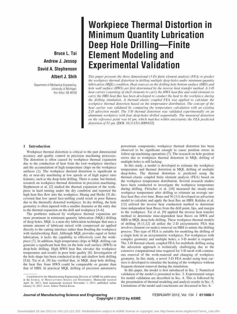
2.2 Heat Carrier Model. The heat carrier model is a 3-DFEA developed in this study to simulate the workpiece tempera-ture distribution in deep-hole drilling. As shown in Fig. 2(a), theheat carrier applies the constant hb and time-dependent hw (bothobtained from the inverse heat transfer method) and moves intothe hole region to conduct the heat to the workpiece. The holeregion is removed prior to the drilling simulation so the heat car-rier can move into it. This is based on the fact that the heat trans-fer in the axial direction is usually much slower than the drill feed
rate; thus, the temperature distribution is not significantly affectedby the heat carrier moving into a void space that represents thehole being drilled. This approach overcomes the practical diffi-culty in 3-D advection model by eliminating the need for remov-ing 3-D elements. As shown by the schematic of 3-D advectionmodel in Fig. 2(b), the cylindrical hole region is partitioned intomany advection layer regions. Unlike the 2-D advection model[Fig. 1(a)], which has a much simpler mesh pattern on eachadvection layer, the number of elements increases significantly ifmany thin layer regions of small 3-D elements are used. In thecase of drilling multiple holes in a workpiece with complex shape,a large number of the 3-D elements are required for each hole andextensive computational time is needed. The heat carrier modelillustrated in Fig. 2(a) simplifies the 3-D FEA procedure.
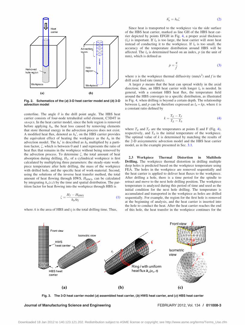
As shown in Fig. 3(a), the heat carrier consisting of HWS andHBS carriers moves at the drilling feed rate to simulate the heatconduction to the workpiece during drilling. Since the heat carrierand workpiece have different meshes, the inconsistent mesh sizesin hole surfaces may cause the elements to intersect each otherand cause the FEA to fail. Therefore, a small gap, 1% of the drilldiameter, is created between matching surfaces of the hole and theheat carrier. To enable the heat transfer through the gap withnearly zero thermal contact resistance, the gap conductance is setrelatively large, 106 W/m2 K, in ABAQUS (version 6.8), which is theFEA software platform used in this study. Details for HWS andHBS heat carriers are described in the following sections.
2.2.1 HWS Heat Carrier. The HWS heat carrier, as shownin Fig. 3(b), is a cylindrical shell consisting of four-nodethermal–elastic coupled shell elements, S4RT in ABAQUS. The ele-ments are configured as many rings along the HWS carrier. Thenumber of rings in the axial direction on the HWS heat carrier isN, which is equal to the number of time steps of hw in the advec-tion model for the inverse heat transfer method. The axial lengthof each ring in the HWS heat carrier is the distance hw movesduring one time step in the advection model. For the ring i (¼ 1,2,..., N), as highlighted in Fig. 3(b), the heat flux is uniformlyapplied with the magnitude of hw(xi,t), where xi is the center posi-tion of the ring i to the HBS and t is time. The heat flux at eachring varies with time as the HWS heat carrier moves into the hole.
2.2.2 HBS Heat Carrier. The HBS heat carrier, as shown inFig. 3(c), is a parallelogram cross-section revolved around the
Fig. 1. (a) 2-D axisymmetric advection FEA model and (b) the corresponding experi-mental setup for the inverse heat transfer method
011008-2 / Vol. 134, FEBRUARY 2012 Transactions of the ASME
Downloaded 18 Jan 2012 to 140.123.121.202. Redistribution subject to ASME license or copyright; see http://www.asme.org/terms/Terms_Use.cfm
centerline. The angle h is the drill point angle. The HBS heatcarrier consists of four-node tetrahedral solid element, C3D4T inABAQUS. In the heat carrier model, since the hole region is removedbefore applying hb, the heat loss caused by removing elementsthat store thermal energy in the advection process does not exist.A modified heat flux, denoted as hb
0, on the HBS carrier providesthe equivalent effect of heating the workpiece as the hb in theadvection model. The hb
0 is described as hb multiplied by a parti-tion factor, f, which is between 0 and 1 and represents the ratio ofheat flux that remains in the workpiece without being removed bythe advection process. To determine f, the total amount of heatabsorption during drilling, HT, of a cylindrical workpiece is firstcalculated by multiplying three parameters: the steady-state work-piece temperature after hole drilling, the mass of the workpiecewith drilled hole, and the specific heat of work-material. Second,using the solutions of the inverse heat transfer method, the totalamount of heat flowing through HWS, HHWS, can be calculatedby integrating hw(x,t) by the time and spatial distribution. The par-tition factor for heat flowing into the workpiece through HBS is
f ¼ HT � HHWS
hbAtf(1)
where A is the area of HBS and tf is the total drilling time. Thus,
h0b ¼ hbf (2)
Since heat is transported to the workpiece via the side surfaceof the HBS heat carrier, marked as line GH of the HBS heat car-rier depicted by points EFGH in Fig. 4, a proper axial thickness(lb) is important. If lb is too large, the heat carrier will store heatinstead of conducting it to the workpiece. If lb is too small, theaccuracy of the temperature distribution around HBS will beaffected. The lb is determined based on an index, p (in the unit ofmm), which is defined as
p ¼ af
(3)
where a is the workpiece thermal diffusivity (mm/s2) and f is thedrill axial feed rate (mm/s).
A larger p means that the heat can spread widely in the axialdirection; thus, an HBS heat carrier with longer lb is needed. Ingeneral, with a constant HBS heat flux, the temperature fieldaround the HBS converges to a specific distribution, as illustratedin Fig. 4, when drilling is beyond a certain depth. The relationshipbetween lb and p can be therefore expressed as lb¼ kp, where k isa constant ratio defined by
k ¼ TE � TF
TE � T0
(4)
where TE and TF are the temperatures at points E and F (Fig. 4),respectively, and T0 is the initial temperature of the workpiece.The optimal value of k is determined by matching the results ofthe 2-D axisymmetric advection model and the HBS heat carriermodel, as in the example presented in Sec. 3.1.
2.3 Workpiece Thermal Distortion in MultiholeDrilling. The workpiece thermal distortion in drilling multipledeep holes is predicted based on the workpiece temperature usingFEA. The holes in the workpiece are removed sequentially andthe heat carrier is applied to deliver heat fluxes to the workpiece.After drilling a hole, there is a time period for the spindle toretract and move to the next hole drilling position. The workpiecetemperature is analyzed during this period of time and used as theinitial condition for the next hole drilling. The temperature isaccumulated and transported in the workpiece as holes are drilledsequentially. For example, the region for the first hole is removedat the beginning of analysis, and the heat carrier is inserted intothe hole to conduct the heat. After the heat carrier reaches the endof this hole, the heat transfer in the workpiece continues for the
Fig. 3. The 3-D heat carrier model (a) assembled heat carrier, (b) HWS heat carrier, and (c) HBS heat carrier
Fig. 2. Schematics of the (a) 3-D heat carrier model and (b) 3-Dadvection model
Journal of Manufacturing Science and Engineering FEBRUARY 2012, Vol. 134 / 011008-3
Downloaded 18 Jan 2012 to 140.123.121.202. Redistribution subject to ASME license or copyright; see http://www.asme.org/terms/Terms_Use.cfm
period of time it takes to start the second hole drilling. The regionfor the second hole is then removed and the heat carrier is insertedwith the same heat fluxes. This procedure is repeated in drillingfollow-up holes.
To predict the thermal distortion, a separate thermal–elasticFEA is applied to avoid solving the displacement and temperaturesimultaneously, which requires extensive computation time in 3-DFEA. Furthermore, the expansion of the workpiece would createcontact with the heat carrier and cause computational errors. Theproposed approach first calculates the workpiece temperature dis-tribution at the specific time of interest. This temperature field isextracted and imported to the thermal–elastic FEA to solve theworkpiece thermal distortion.
3 Numerical Validation
The heat carrier model was validated numerically by comparingthe calculated workpiece temperature with the existing solutionusing the 2-D advection model [13]. The selected case was dril-ling a 10 mm diameter, 200 mm deep hole along the centerline ofa 40 mm diameter solid cylindrical ductile iron workpiece. Byapplying the heat fluxes hb (¼ 3.10 MW/m2) and hw(x,t) in theadvection model [13], the steady-state workpiece temperaturecan be solved. Consequently, HT¼ 7.89 kJ and HHWS¼ 2.20 kJare calculated. Using Eq. (1) with tf¼ 50 s, f¼ 48% andhb0 ¼ 1.49 MW/m2.The validation includes two parts: one verifies the HBS heat
carrier model and lb (Sec. 3.1) and the other compares the differ-ence of workpiece temperature predicted using the 2-D advectionand 3-D heat carrier models (Sec. 3.2).
3.1 HBS Heat Carrier Model Validation. To find the opti-mal k for the axial thickness (lb) and validate the modified heatflux (hb
0), a 2-D axisymmetric HBS heat carrier, converted fromthe 3-D HBS heat carrier [Fig. 3(c)] with only hb
0 applied, wascompared with the 2-D advection model with only hb applied. Themodel had 140 deg point angle and 10 mm diameter hole (the drillused in this study). Based on the work-material and drilling feedrate, p can be determined to calculate lb with a given k value, asdescribed in Sec 2.2.2. The optimal k is selected from four values,80%, 70%, 60%, and 50%, with an interval of 10% since k doesnot significantly affect the overall workpiece temperature. Inthe case of a ductile iron workpiece and 4 mm/s feed rate, a is6.89 mm2/s and p is 1.72 mm. Figures 5(a) and 5(b) show the tem-perature distributions at 100 mm drilling depth in the 2-D advec-tion mode and the heat carrier model with k¼ 60% (lb¼ 1.6 mm),respectively. Temperature distributions of a 16 mm by 8 mm
region highlighted in Figs. 5(a) and 5(b) were overlaid in Fig. 5(c)for comparison. The best R2 (¼ 0.97) was found for k¼ 60%. Bytesting k values under different p (adjusted by feed or materialproperties), the optimal k was also found either 50% or 60%. Inthis study, k¼ 60% was selected to find lb.
To cover a wide range of feed rates on different work-materials, as shown in Fig. 6, six cases ranging from p¼ 0.4 mmto 13.7 mm were applied in the advection model to find the corre-sponding lb based on the temperature distribution and k¼ 60%.This range includes the drilling conditions for iron at 0.5 to16 mm/s feed rate and aluminum at 5.5 to 150 mm/s feed rate.Therefore, the lb can be obtained from Fig. 6 with a given work-material and drilling feed rate for a specific type of drill.
3.2 3-D Heat Carrier Model Validation. The assembledheat carrier [Fig. 3(a)] was applied in 3-D FEA with a cylindrical
Fig. 5. Temperature distributions around HBS in (a) 2-D advec-tion model and (b) 2-D HBS heat carrier with k 5 60%, and (c)the comparison of temperature results in the regions high-lighted in (a) and (b)
Fig. 4. Definition of axial thickness (lb), the geometry (EFGH)of the 2-D axisymmetric HBS heat carrier, and convergent tem-perature distribution due to constant HBS heat flux
Fig. 6. The lb determined by index p ranging from 0.4 to13.7 mm with k 5 60%
011008-4 / Vol. 134, FEBRUARY 2012 Transactions of the ASME
Downloaded 18 Jan 2012 to 140.123.121.202. Redistribution subject to ASME license or copyright; see http://www.asme.org/terms/Terms_Use.cfm
workpiece model to calculate the temperatures at selectedpositions for comparison with the 2-D advection modelingresults. For the 3-D HBS heat carrier, the size and shapecorresponded to the 2-D axisymmetric HBS heat carrier in theprevious section with lb¼ 1.6 mm. For the HWS heat carrier,there were 125 rings on the 200 mm long cylindrical shell. Themodel’s initial temperature was set to 20 �C. Figure 7(a) showsthe workpiece surface temperature at time 24.8 s (¼ 99.2 mmdrilling depth) using the 3-D heat carrier model. The highest sur-face temperature is about 30 �C at 50 mm from the top surface.As shown in Fig. 7(b), five points that are 3.4 mm from HWSand positioned along the axial length were selected to comparethe temperature versus time predicted using both models. Themaximum discrepancy, as shown in Fig. 7(b), is about 5% at thepeak temperature. At the end of drilling, the average tempera-tures at the five points are 31.3 �C and 31.9 �C for the 3-D heatcarrier and 2-D advection models, respectively. Overall, theagreement of the results from two models validates the proposed3-D heat carrier model.
4 Experimental Setups
The deep hole drilling experiment was conducted on a Fadalvertical machining center (Model VMC 4020). The feed rate andspindle speed were set at 0.2 mm/rev and 2100 rpm, respectively.A 10 mm diameter, 220 mm long solid carbide drill with oil feedholes (Titex, Model A6785TFP-10) was used. An AMCOL fluiddelivery system was used to supply the MQL fluid and air mix-ture. The compressed air supply for the MQL system was regu-lated to 500 kPa (5 bar). The MQL fluid was Milacron CIMFREEVG-703ES. The flow rate was approximately 60 mL/h while at2100 rpm spindle speed.
Aluminum 6061-T6 was chosen as the work-material in thisstudy. Two sets of experiments were conducted in this study. Thefirst, setup I, was the drilling of a cylindrical workpiece for theinverse heat transfer solutions of heat fluxes hb and hw. The sec-ond, setup II, was to validate the thermal distortion predicted bythe 3-D heat carrier model.
4.1 Setup I—Determination of Drilling Heat Fluxes. Figure8 shows setup I, used to find the HBS and HWS heat fluxes. Thecylindrical workpiece was 38 mm in diameter and 152 mmin length. Five type E thermocouples (OMEGA Model 5TC-TT-E-36-72) with 0.127 mm wire diameter were embedded inthe workpiece at 3.4 mm from HWS and 30 mm apart from eachother. These thermocouples are marked as TC1, TC2, TC3,TC4, and TC5 in Fig. 8. The 3.4 mm distance to HWS was cho-sen to avoid the large temperature gradient near HWS, whichcould potentially cause measurement errors and affect the accu-racy of the heat flux estimation [9]. The thermocouple holeswere 1.2 mm in diameter and filled with the thermal paste tominimize the thermal contact resistance. A 10 mm diameterthrough hole was drilled at the center of the workpiece underthe MQL condition using the 10 mm diameter carbide drill. Thetotal drilling time was 21.7 s. The temperatures were recordedat a 10 Hz sampling rate.
4.2 Setup II—Workpiece Thermal Distortion. Figure 9(a)shows the shape and dimensions of the workpiece in setup II,used to measure the workpiece thermal expansion after the MQLdrilling of four deep holes. A picture of the experimental setupfor setup II is shown in Fig. 9(b). The workpiece was a 50.8 mm� 152 mm� 152 mm aluminum block with a 25.4 mm deep and25.4 mm wide region sticking out of the bottom on one side forclamping. This design is aimed to avoid introducing significantconstraints to the workpiece thermal expansion in the X-direction[marked in Fig. 9(a)] during drilling. The origin of the XYZ coor-dinate system was set at the corner of the top surface [point O inFig. 9(a)].
Four 152 mm deep through holes, marked as #1, #2, #3, and#4 in Fig. 9(a), were drilled into the workpiece in sequence usingthe same drill, spindle speed, and feed rate as in setup I. Four shal-low reference holes, marked as a, b, c, and d, were drilled 18 mmdeep with a 9.5 mm drill. Holes a and b were drilled prior to dril-ling the four deep holes. Holes c and d were drilled right afterthe drilling of four deep holes. The difference of distance in theX-direction between holes a and b to holes c and d and the pro-grammed nominal X-position [127.0 mm in Fig. 9(a)] in themachine determines the experimentally measured thermal expan-sion of the workpiece. This experimental measurement value iscompared with the predicted thermal expansion in the X-directionusing 3-D heat carrier model.
Fig. 7. (a) Surface temperature at 24.8 s drilling time in 3-Dheat carrier model and (b) temperature comparison between3-D heat carrier model and 2-D advection model
Fig. 8. Setup I: Cylindrical workpiece with five thermocouplesembedded along the depth for the inverse heat transfer method
Journal of Manufacturing Science and Engineering FEBRUARY 2012, Vol. 134 / 011008-5
Downloaded 18 Jan 2012 to 140.123.121.202. Redistribution subject to ASME license or copyright; see http://www.asme.org/terms/Terms_Use.cfm
The position of reference holes were measured by using a dialindicator on the machine spindle, as shown in Fig. 9(b), after theworkpiece was cooled to the room temperature. The accuracy ofthe machine’s positioning in the X axis was measured with aRenishaw laser interferometer (Model ML 10). The machine axisresolution was 2 lm. Laser interferometry measurements showedthe machine X axis position error was below 5 lm. The resolutionof the dial indicator was also below 5 lm. The hole positionmeasurement error using the dial indicator in the machine wasestimated to be less than 10 lm.
For validating the workpiece temperature in FEA, three thermo-couples, marked as A, B, and C, as shown in Fig. 9(b), wereattached on the workpiece surface for measuring the surfacetemperature during drilling.
5 Modeling and Experimental Results
The inverse heat transfer solution of hb and hw, workpiece tem-perature, and workpiece thermal distortion are presented in thefollowing three sections.
5.1 Heat Fluxes on HBS and HWS (Setup I). Using themeasured temperatures at five thermocouples [Fig. 10(a)], the
heat fluxes were determined based on the inverse heat transfermethod [9]. The calculated hb is 4.5 MW/m2. The hw, as a functionof time and drill position, is shown in Fig. 10(b). By applying theheat fluxes in the 2-D advection model, the calculated tempera-tures at the five thermocouple positions were compared with themeasured data in Fig. 10(a). The overall good agreement betweenthe FEA and measured temperatures verifies the inverse heattransfer method for aluminum, which is a new work-material nottested in our previous studies [9,13]. There is some discrepancyfor TC1 in the early stage of drilling (2 to 5 s). This phenomenonhas been observed in Ref. [13] due to the fast heat flux changethat cannot be captured by the hw model in the inverse heat
Fig. 9. Setup II: (a) workpeice design for thermal distortionexperiment and (b) the measurement of hole positions usingdial indicator (unit: mm)
Fig. 10. Results of the inverse heat transfer method: (a) meas-ured and FEA calculated temperatures at thermocouple posi-tions and (b) temporal and spatial distribution of hw
Fig. 11. The 3-D FEA mesh of the workpiece for multiholedrilling
011008-6 / Vol. 134, FEBRUARY 2012 Transactions of the ASME
Downloaded 18 Jan 2012 to 140.123.121.202. Redistribution subject to ASME license or copyright; see http://www.asme.org/terms/Terms_Use.cfm
transfer method. Two tests were conducted under the same dril-ling condition in this experiment, and the temperature data wererepeatable.
5.2 Workpiece Temperature (Setup II). The 3-D heat car-rier model was applied. For the HBS heat carrier, the diffusivityof aluminum 6061 was 74.4 mm2/s and the drilling feed rate was7 mm/s; thus, the index p was 10.6 mm. Based on Fig. 6 withk¼ 60%, the HBS carrier thickness lb was determined to be5.6 mm. The partition factor was 0.82 and thus hb’¼ 3.7 MW/m2.For the HWS heat carrier, 100 rings (N¼ 100) were created alongthe 152 mm length. This corresponded to 1.52 mm ring axiallength, which was finer than that in the validation case (1.6 mm)in Sec. 3. The time-dependent hw [Fig. 10(b)] calculated by theinverse heat transfer method was applied on each ring.
The 3-D FEA mesh of the workpiece prior to inserting the heatcarrier to hole #1 is shown in Fig. 11. The region for hole #1 hadbeen removed. The heat carrier [Fig. 3(a)] moved at a speed of
7 mm/s (feed rate of the drill) into the hole to conduct heat fluxes(hw and hb
0) into the workpiece. Figure 12(a) shows the surfacetemperature distribution at the time when the heat carrier pene-trates the bottom of the workpiece for hole #1. The highest tem-perature is close to the bottom of the workpiece, near hole #1. Thetemperature distribution in the workpiece after 6.5 s taken toretract the drill and move to the position for hole #2 is shown inFig. 12(b), which is also the initial workpiece temperature for dril-ling hole #2. The region for hole #2 was then removed, the work-piece was remeshed, and the heat carrier was inserted to deliverheat fluxes. The workpiece temperature after drilling hole #2 isshown in Fig. 12(c). The workpiece temperature after drillingholes #3 and #4 are shown in Figs. 12(d) and 12(e), respectively.The higher temperature region visible in Fig. 12(d) is due to hole#3 being close to the workpiece front surface. The gradualincrease of overall workpiece temperature can be observed as theholes are drilled sequentially.
Temperatures at points A, B, and C (Fig. 9) were extractedfrom FEA and compared to experimental measurements. As
Fig. 12. Workpiece temperature distribution at (a) the end of drilling hole #1, (b) 6.5 s after theend of drilling hole #1, and the end of drilling (c) hole #2, (d) hole #3, and (e) hole#4
Fig. 13. Measured and predicted surface temperatures atpoints A, B, and C
Fig. 14. Two viewpoints of workpiece temperature distributionin 22 s after the end of hole #4 drilling
Journal of Manufacturing Science and Engineering FEBRUARY 2012, Vol. 134 / 011008-7
Downloaded 18 Jan 2012 to 140.123.121.202. Redistribution subject to ASME license or copyright; see http://www.asme.org/terms/Terms_Use.cfm
shown in Fig. 13, these temperatures match very well except nearthe peaks at points A and B. Further investigation shows that thediscrepancy is due to the limitation of hw spatial resolution closeto the drill tip.
After a 22 s time lag for tool change and positioning the drillfor the reference holes c and d, the workpiece temperature distri-bution is shown in Fig. 14 on both sides of the workpiece. This isthe temperature used for the thermal–elastic FEA to calculate theworkpiece thermal distortion. The peak temperature is about37.5 �C at the corner of the workpiece bottom close to hole #4.The low temperature, close to hole #1, is 31.5 �C. The temperaturegradient is observed along the X-direction.
5.3 Workpiece Distortion (Setup II). The temperature dis-tribution in Fig. 14 was remeshed to the 8-node linear brick ele-ment (C3D8R in ABAQUS) and the thermal–elastic FEA wasperformed to simulate the workpiece thermal expansion. The FEApredicted workpiece thermal expansion in the X-direction isshown in Fig. 15, where the contour represents the displacementin X-direction. The workpiece thermal distortion across the YZplane is almost uniform.
The FEA model predicted that the thermal expansion betweentwo sets of reference holes (holes c and d versus holes a and b) is51 lm. With the potential measurement error of 10 lm, this valueis comparable to the experimentally measured 61 lm and vali-dated the proposed FEA 3-D heat carrier and thermal distortionmodel for predicting the workpiece thermal distortion in MQLdeep-hole drilling.
6 Conclusions
In this study, the heat carrier model was proposed and experi-mentally verified to predict the 3-D workpiece temperature distri-bution and thermal distortion. This approach had demonstrated tobe practical, universal, computationally time efficient, and feasi-ble to study the thermal distortion of MQL multihole drilling. Themethod could be used to design the clamping layout to minimizethermal distortion, for selection of machining parameters, and forerror compensation in the MQL machining operations to improvepart accuracy. Heat fluxes of this thermal distortion model wereassumed to be repeatable in each hole drilling. The effect of drillwear and gradual increase in drilling force, torque, and heat fluxescould be included in future study.
In the heat carrier model, the method of removing the entirehole prior to the drilling would remove some of the heat thatpotentially conducts to the workpiece during the time of drilling.The error associated with this approach is limited if the distancebetween holes is large or the drill feed rate is relatively fast com-pared to the thermal diffusion of the work-material. To minimizethis potential error, a deep hole can be divided into several seg-ments and then removed sequentially. This step-removal approachis investigated in this study by dividing each hole into three seg-ments with equal depth. In total, 12 segments for the four holeswere removed and the heat carrier inserted into each of the seg-ments sequentially. For example, Fig. 16(a) shows the removed1st segment of hole #2 with the heat carrier midway through thissegment. Figures 16(b) and 16(c) show the removal of second andthird segments of hole #2, respectively, with the heat carrierinserted further. The discrepancy between the initial approach andthe step-removal approach of temperatures at points A, B, and C(Fig. 9) 22 s after drilling hole #4 was only 0.3%. This confirmedthat the step-removal approach is not necessary in this study.
Appendix
In Sec. 3, the total heat absorption for the given example is cal-culated by
HT ¼ ðTf � TiÞqcpw2
4� D2
4
� �l
¼ ð30:55� 20Þð7000Þð506Þp ð0:038Þ2
4� ð0:01Þ2
4
!ð0:2Þ
¼ 7890J
where Tf is the final steady-state temperature and Ti is the initialworkpiece temperature. The w and D are the diameters of work-piece and drill (hole), respectively; q and c are the workpiece den-sity and specific heat, respectively. The heat contributed by HWSheat flux is calculated by
Fig. 15. Simulated workpiece distortion in X-direction at thestart of drilling the reference holes
Fig. 16. Step-removal approach in the heat carrier model
011008-8 / Vol. 134, FEBRUARY 2012 Transactions of the ASME
Downloaded 18 Jan 2012 to 140.123.121.202. Redistribution subject to ASME license or copyright; see http://www.asme.org/terms/Terms_Use.cfm
HHWS ¼ðtf
0
ðl
0
hwðx; tÞpDdxdt ¼ 2:20 kJ
where t is time and x is the axial position along the hole. Totaltime tf is 50 s and total depth l is 0.2 m.
References[1] Stephenson, D. A., and Agapiou, J. S., 2006, Metal Cutting Theory and Prac-
tice, 2nd ed., Taylor and Francis, Boca Raton, FL.[2] Stephenson, D. A., Barone, M. R., and Darqush, G. F., 1995, “Thermal Expan-
sion of the Workpiece in Turning,” J. Eng. Ind., 117, pp. 542–550.[3] Huang, Y., and Hoshi, T., 2000, “Improvement of Flatness Error in Milling
Plate-Shape Workpiece by Application of Side-Clamping Force,” Precis. Eng.,24, pp. 364–370.
[4] Haan, D. M., Batzer, S. A., Olson, W. W., and Sutherland, J. W., 1997, “An Ex-perimental Study of Cutting Fluid Effects in Drilling,” J. Mater. Process. Tech-nol., 71, pp. 305–313.
[5] Bono, M., and Ni, J., 2001, “The Effects of Thermal Distortions on the Diame-ter and Cylindricity of Dry Drilled Holes,” Int. J. Mach. Tools Manuf., 41, pp.2261–2270.
[6] Kalidas, S., Kapoor, S. G., and DeVor, R. E., 2002, “Influence of ThermalEffects on Hole Quality in Dry Drilling, Part 2: Thermo-Elastic Effects on HoleQuality,” ASME J. Manuf. Sci. Eng., 124, pp. 267–274.
[7] Stoll, A., Sebastian, A. J., Klosinski, R., and Furness, R., 2008, “MinimumQuantity Lubrication (MQL) is a Key Technology for Driving the ParadigmShift in Machining Operations,” SAE Paper No. 01-1128.
[8] Agapiou, J., 2010, “Development of Gun-Drilling MQL Process and Toolingfor Machining of Compacted Graphite Iron (CGI),” Trans. NAMRI/SME, 38,pp. 73–80.
[9] Tai, B. L., Stephenson, D. A., and Shih, A. J., 2011, “An Inverse Heat TransferMethod for Determining Workpiece Temperature in MQL Deep Hole Drilling,”ASME J. Manuf. Sci. Eng., accepted.
[10] Fleischer, J., Pabst, J., and Keleman, S., 2007, “Heat Flow Simulation for DryMachining of Power Train Castings,” Ann. CIRP, 56, pp. 117–122.
[11] Bono, M., and Ni, J., 2002, “A Model for Predicting the Heat Flow Intothe Workpiece in Dry Drilling,” ASME J. Manuf. Sci. Eng., 124, pp.773–777.
[12] Kalidas, S., Kapoor, S. G., and DeVor, R. E., 2002, “Influence of ThermalEffects on Hole Quality in Dry Drilling, Part 1: A Thermal Model of WorkpieceTemperatures,” ASME J. Manuf. Sci. Eng., 124, pp. 258–266.
[13] Tai, B. L., Stephenson, D. A., and Shih, A. J., 2011, “Air Pressure and FeedRate Effects on Workpiece Temperature in MQL Deep Hole Drilling,” Int. J.Mach. Tools Manuf.
Journal of Manufacturing Science and Engineering FEBRUARY 2012, Vol. 134 / 011008-9
Downloaded 18 Jan 2012 to 140.123.121.202. Redistribution subject to ASME license or copyright; see http://www.asme.org/terms/Terms_Use.cfm