48
W843-2 For Models: M843NW2, NL843NW2, and NL843N2 WORKSHOP MANUAL Marine Generators | Marine Diesel Engines | Land-Based Generators

W843-2For Models: M843NW2, NL843NW2,
and NL843N2
WORKSHOP MANUAL
Marine Generators | Marine Diesel Engines | Land-Based Generators

Diesel engine exhaust and some of its constitu-ents are known to the State of California to cause
cancer, birth defects, and other reproductive harm.
— CALIFORNIA —Proposition 65 Warning:
Northern Lights4420 14th Avenue N.W.Seattle, WA 98107Tel: (206) 789-3880Fax: (206) 782-5455
Copyright ©2007 Alaska Diesel Electric, Inc.All rights reserved. Northern Lights™, andthe Northern Lights logo are trademarks ofAlaska Diesel Electric, Inc.
Printed in U.S.A.PART NO.: W843-2 04/07

W843-2 04/07
3
1. DISASSEmbLy PROCEDURES ............................................................5- 8 Safety Instructions........................................ 4
2. INSPECTION OF ENgINE mAIN COmPONENTS a. Rocker Arm ...........................................9 b. Cylinder Head ...............................10- 12 c. Cylinder block ......................................12 d. Piston & Piston Rings.....................13- 14 e. Connecting Rod .............................14- 15 f. bearing Holder ...............................15- 16 g. Crankshaft bearing .............................16 h. Crankshaft ............................................17 i. Flywheel & Ring gear ..........................17 j. Camshaft Assembly .............................18 k. Timing gear .........................................18 l. Oil Pump ..............................................19 m. Oil Filter ................................................19 n. Coolant Pump ......................................19 o. Thermostat ...........................................20 p. Radiator................................................20 q. Fuel Filter .............................................20 r. Injection Pump .....................................21 s. Nozzle and Holder..........................22- 23
3. REASSEmbLy OF ENgINE mAIN COmPONENTS ..........................24- 30 Head gasket ..................................................28
4. ELECTRICAL SySTEm INSPECTION
Fuel Solenoid .................................................31 glow Plugs.....................................................32 Oil Pressure Switch .................................32- 33 Alternator maintenance Chart ........................34 Alternator Troubleshooting.............................35 Starter ......................................................36- 40
5. TROUbLESHOOTINg ........................42- 44
6. ENgINE mAINTENANCE STANDARDS ......................................................45- 48
Alaska Diesel Electric reserves the right to carry out any design modifications and, for this reason, some of the contents of this manual may not apply to your engine. If further information is needed, we suggest that you contact an authorized dealer or the ADE factory.
WORKSHOP MANUALfor Models
M843NW2, NL843NW2, and NL843N2
ProprietaryInformationThispublicationisthepropertyof AlaskaDieselElectric,Inc.
Itmaynotbereproducedinwholeorinpartwithoutthewrittenpermissionof AlaskaDieselElectric,Inc.©AlaskaDieselElectric,Inc.Allrightsreserved.LithoU.S.A.PublicationnumberW843-204/07
TABLE OF CONTENTS

W843-2 04/07
4
CAUTION: This symbol is used throughout this book to alert you to possible danger areas. Please take special notice of these sections.
SAFETY RULES
• Use caution in handling fuel. Never refuel a hot or running engine. Do not smoke while filling fuel tank or servicing fuel system.• Keep your hands, feet, hair and clothing away from power-driven parts.• Check for any loose electrical connections or faulty wiring.• Engines should be operated only by knowledgeable, qualified personnel.• Look completely around engine to make sure that everything is clear and clean before starting.• Do not operate an engine that isn't in proper working order. If an unsafe operating condition is noted, tag the set and control panel so others will also know about the problem.• Provide first aid kits.• Do not disassemble parts or engine except for what is needed to be worked on - as initially the engine was put together with precision that could prove hard to duplicate.• Apply oil to moving parts during reassembly to form an oil film to fill up the gap before regular lubrication occurs.
CAUTION: Accident reports show that careless use of engines causes a high percentage of accidents. You can avoid accidents by observing these safety rules. Study these rules carefully and enforce them on the job.
• Never leave engine without proper security.• Turn the coolant tank cap slowly to relieve pressure before removing. Add coolant only when the engine is stopped and cool.• Mount a fire extinguisher near engine.• Always disconnect the battery ground strap before making adjustments.• Operate engines in properly ventilated areas.• Keep trash and other objects away from engine.• Escaping fluids under pressure can penetrate your skin. Use a piece of cardboard or wood, not your hands, to search for leaks.• Avoid wearing loose clothing without a belt when working around engines.• Do not oil or grease engine while it is running.
Introduction

W843-2 04/07
5
Engine Overall Disassembly
1 Alternator 2 Oil Filter 3 Relief Valve 4 Dipstick 5 Engine stop solenoid, seal washer 6 Injection pipe 7 Injection pump assembly Remove the injection lines and stop solenoid before removing the injection pump. Raise the injection pump and disconnect the governor link from the control rack by removing the snap pin. The injection timing has been adjusted by the shims between the injection pump and cylinder block; record the thickness and number when removing the injection pump.
ISMcylblockwithalt
SECTION 1 – DISASSEmbLy PROCEDURES
SEQUENCE PART DISASSEmbLy ESSENTIALS

W843-2 04/07
6
Engine Overall Disassembly
ISmblockwithrockercover
SECTION 1 – DISASSEmbLy PROCEDURES
SEQ. PART DISASSEMBLY ESSENTIALS
8 Return pipe 9 Injection nozzle, gasket 10 Oil transfer tube, banjo bolt, seal washer 11 Connector, glow plugs 12 Oil pressure switch 13 Thermostat housing, gasket 14 Rocker arm cover, o-ring, intake manifold, spacer 15 Rocker arm assembly, o-ring, cap Remove the caps from intake valves 16 Push rod and exhaust valves. 17 Cylinder head, head gasket Loosen the cylinder head bolts in 18 Tappet several steps and remove the cylinder
head assembly.

W843-2 04/07
7
19 V-belt, cooling fan, fan housing, fan pulley 20 Water pump assembly, gasket 21 Crankshaft pulley 22 Timing gear case assembly, gasket First remove the injection pump 23 Idle gear, oil pump assembly assembly and the stop solenoid. 24 Camshaftassembly,plate Removetheboltsandplatefirstandpull 25 Front plate, gasket out the camshaft assembly.
ISmvbelt&fan
SECTION 3 – DISASSEmbLy PROCEDURES
SEQ. PART DISASSEMBLY ESSENTIALS
Engine Overall Disassembly

W843-2 04/07
8
ISmblockwithcrankshaft
SECTION 1 – DISASSEmbLy PROCEDURES
SEQ. PART DISASSEMBLY ESSENTIALS
27 Oilpan,gasket,intakefilter,intakepipe 28 Flywheel 29 Rear plate 30 Oil seal 31 Piston and connecting rod assembly Remove the carbon deposit from the top 32 Crankshaft and bearing holder assembly of the cylinder before taking out the piston. Keep the connecting rod, cap, and bearing
in the order of the cylinders as they are removed.
Take out the bolts for the bearing holders and remove the crankshaft and bearing holder as a set.
Engine Overall Disassembly

W843-2 04/07
9
Engine main Parts Inspection
Notes before assembly:1. Check for wear and leakage on the cylinder block and the cylinder head.2. Check for clogs in oil holes on parts and remove deposits with air.3. Wash each part completely to remove contaminates, oil, carbon, etc...4. For the piston, cylinder, and valves take care in removing deposits (aluminum alloy parts need extra care).5. Valves, pistons, connecting rods, metals, and other parts that are to be put back together should bemarkedwiththeirmatchessothattheycanbere-fittedwithgreaterease.
A) Rocker Arm Assembly Disassembly and Inspection 1 Screw 2 Rocker arm shaft 3 Rocker arm Screw in a m8 bolt at the front end of the rocker arm 4 Spring shaft and take out the rocker arm shaft. 5 Shim Take out the spring, shim, and rocker arm from the
rocker arm bracket.
ISminspec.pg1a
SECTION 2 – INSPECTION PROCEDURES
1 Using a micrometer, check outside diameter of the rocker arm shaft. If the shaft wear exceeds the service limit shown, replace it. Wear of rocker arm shaft (mm) Standard assembly value Service limit 14.95 - 14.97 14.87
ISminspec.pg1b
2 measure the inside diameter of the rocker arm. Calculate the clearance between the rocker arm and rocker arm shaft. If the clearance is past the service limit replace the part. Clearance between rocker arm and rocker arm shaft (mm) Standard assembly value Service limit 0.032 - 0.068 More than 0.2
3 Check the valve cap-contact surface for uneven wear and streaks. Smooth the surface with an oilstone or grinder if needed.

W843-2 04/07
10
SECTION 2 – INSPECTION PROCEDURES
b) Cylinder Head Assembly 1 Valve guide seal 2 Spring 3 Retainer Using a valve spring replacer, compress the valve 4 Valve spring to remove the valve keeper, retainer, spring, 5 Valve keeper and valve. Then remove the valve guide seal.
ISminspec.pg2a
1. To measure the distortion of the cylinder head bottom surface; apply a straight edge to the bottom surface of the cylinder head and insert a gauge to measure thickness at 6 points from A to F as shown above. If the distortion measured exceeds the repair value as shown below, smooth with a surface grinder or something similar.
Distortion at cylinder head bottom surface (mm) Standard assembly value Repair value Less than 0.05 More than 0.12
ISminspec.pg2b
2. Valve guide and stem: Inspect the head and stem of each valve and replace if damaged or badly worn. measure the outside diameter at 1,2,3 positions (figure at right) with a micrometer and replace if the result is less than the service limit as seen in the below table.
Wear of valve stem o (mm) Intake Valve Exhaust Valve Standard Service Standard Service assembly Limit assembly Limit value value 6.955-6.97 6.89 6.94-6.95 6.84
3. Valve head: If the head thickness is less than the service limit below, replace.
ISminspec.pg2c
ISminspec.pg2d
Valve head thickness (mm) Standard assembly value Service Limit 0.8-1.1 Less than 0.5
Engine main Parts Inspection

W843-2 04/07
11
Engine main Parts Inspection
4. Valve guide and Valve: If the clearance between the valve stem and guide exceeds the service limit, replace the valve.
ISmstem&guide
SECTION 2 – INSPECTION PROCEDURES
ISmvalveseatrecess
Clearance between valve stem and guide Intake Valve Exhaust Valve Standard Service Standard Service assembly Limit assembly Limit value value 0.03-0.06 More than 0.2 0.045-0.075 More than 0.25
5. Valve Seat:Checkthevalveguidefirstforwearconditionbefore correcting the valve seat as the valve seat is corrected according to the valve guide.Use seat cutter of 15°, 45°, and 75° to correct the seat to the standard assembling values.
Valve Seat Contact Width (mm) Standard assembly value Repair value Intake 1.77-1.19 2.5 Exhaust 1.87-2.09 2.5
ISmvalveseatwidth
6. Replace the cylinder head if the seat recess exceeds the service limit.
Distortion at cylinder head bottom surface (mm) Standard assembly value Repair value Less than 0.05 More than 0.12
7. To correct the valve seat, coat the valve seat with compound and lap the contact surface turning the valve. make sure the valve contact surface is within the standard value and the contact position is even. If the cylinder head is replaced with a new one, adjust the seat contact width and seat recess to the specifiedvalues(see above tables) with a seat cutter before lapping.
ISmvalvelapper

W843-2 04/07
12
8. Valve Spring Check the valve spring for damage.measure the squareness of the spring using a square on a surface plate and if the surface limit is exceeded, replace the spring. Check the free length and spring force with a spring tester and replace the spring if the service limit is exceeded.
Standard Service assembly value Limit Squareness (mm) 1.2 2 Free Length 35 33.5 Spring force (compressed 79.8 N 68.6 N to 30.4 mm) (8.1 kgf) (7 kgf)
SECTION 2 – INSPECTION PROCEDURES
Engine main Parts Inspection
ISmspring
Reassembly Reassemble the components in the reverse order to that previously discussed.Take care to not damage the valve guide seal when assembling the valve spring, retainer,and cotter. Tighten the glow plugs to: 15-20 N•m (1.5~2.0 kgf•m)
C. Cylinder block
Check for cracks and damage on the top of the block just like on the cylinder head. There should be no scratches, rust, or corrosion in the cylinder bore. measure the cylinder bore at the top, center, and the bottom in the crankshaft direction (Aonfigure to the right) and also right angle to it (b). Replace the engine long block if the repair value in exceeded.
Distortion at cylinder block top surface (mm) Standard assembly value Repair value Less than 0.05 More than 0.12
Cylinder bore diameter (mm) Standard assembly value Repair value 84 - 84.019 84.2
Replace with long block assembly
ISmringslide

W843-2 04/07
13
D. Piston and Piston RingTo disassemble - use a piston ring tool to remove the piston ring. Then remove the snap ring and extract the piston pin.
ISmpiston1. Inspection of the Piston:Check the outside of the piston for cracks, streaks, or burnouts, replace if needed.measure the bore of the cylinder in the thrust direction, and measure the longer diameter 10 mm above the lower end of the piston skirt. Calculate the clearance and replace if it exceeds the repair value.Also measure the piston pin hole diameter and piston pin outside diameter, replace if the clearance exceeds the service limit.
Clearance between cylinder and piston (mm) Standard assembly value Service limit 0.0375- 0.0715 0.25
Piston skirt bottom longer diameter o (mm) Standard assembly value Service limit 83.948- 83.963 83.7
ISmbore
Clearance between piston pin hole and piston pin (mm)
Standard assembly value Service limit -0.001~ + 0.011 0.02
ISmpistonringgap
2. Inspection of the Piston ring:Replace worn out or damaged piston rings.3. To measure the clearance of the piston, insert a ring at a right angle to the least worn out skirt of a cylinder and measure the clearance of the ring end gap with a thickness gauge. Replace it if the end gap exceeds the service limit.
Piston ring end gap (mm) Standard assembly value Service limit Top Ring 0.20- 0.35 1.0Second Ring 0.20- 0.40 1.0Oil Ring 0.25- 0.50 1.2
SECTION 2 – INSPECTION PROCEDURES
Engine main Parts Inspection
ISmpistondia

W843-2 04/07
14
Engine main Parts Inspection
SECTION 2 – INSPECTION PROCEDURES
D. Piston and Piston Ring continued
4. measure the clearance between the piston ring groove and ring and replace it if the service limit is exceeded.
5. Install the piston ring to the piston as showninthefigureontheright.
Inspection of the Piston Pin 1. measure the outside diameter of the piston pin and replace if the service limit as shown below is exceeded.
Piston outside diameter o (mm) Standard assembly value Service limit 27.994 - 28.0 27.97
Clearance between piston ring groove and ring (mm) Standard assembly value Service limit Top Ring 0.07- 0.11 0.25Second Ring 0.04- 0.08 0.25Oil Ring 0.02- 0.06 0.25
E. Connecting Rod
1. Check the rod for torsion, parallelism, and possible damage. Using a connecting rod aligner, measure the torsion and parallelism. Replace or correct the rod if the repair value is exceeded.
ISmconnectingrod1. Gauge2. Piston pin3. Torsion4. Flat part of aligner5. Pin
Torsion and parallelism of connecting rod (mm) Standard assembly value Repair value Torsion (per 100 mm) Less than 0.08 0.2Parallelism (per 100 Less than 0.05 0.15mm)
2. measure the bore of the connecting rod small end bush and replace it if the clearance to the piston pin exceeds the service limit.3. measure the axial play after re-attaching the connecting rod to the crankshaft, replace the connecting rod if the service limit is exceeded. Axial play of connecting rod and crank pin (mm)
Standard assembly value Service limit 0.1 - 0.3 More than 0.7
Clearance between bush and piston pin (mm) Standard assembly value Service limit 0.010 - 0.027 More than 0.08
ISmpistonring

W843-2 04/07
15
Crankshaft pin outside oFinishing dimension o (mm) 51.964 - 51.975
Connecting Rod metal
1. Check the metal and replace it if peeling, melting, or other damage is noticed.2. Use the plasti-gauge and measure the oil clearance of the crank pin and metal. Remove any foreign matter or oil dust stuck to the metal or crank pin. Cut the plasti-gauge to the same length as the metal width and put it on the crankpin parallel with the crankshaft, avoiding the oil hole. Install the connecting rod metal and connecting rod cap and tighten to below specifiedtorque.Note: Do not turn the connecting rod.
Tightening torque: 49 - 54 N•m (5.0 - 5.5 kgf•m) [36 - 39.8 ft.•lb.]
3. Remove the connecting rod cap and measure the plasti-gauge width, the widest part of the plasti-gauge, with the scale printed on the gauge envelope. If the oil clearance exceeds the service limit, replace the metal.
Reassembly of the Piston and Connecting Rod
1. Heat the piston to about 100°C with a piston heater and install while aligning the SHIbAURA mark in the piston and match mark at “A” of the connectingrod(asseenonrightfigure),usingcare at the match marks.2. Install the piston ring to the piston facing the stamp up towards the end surface of the ring end gap.
Clearance between crank pin and connecting rod metal (Oil clearance) (mm) Standard assembly value Service limit 0.035 - 0.085 0.2
Set a plasti-gauge Measure the oil clearance
ISmpiston-connrodF. bearing Holder
1. Remove the center bearing holder and replace the metal if peeling, melting, improper contact, or other damage is noticed. Replace the thrust washer also if any damage is noticed or if the thickness exceeds the service limit.2. measure the oil clearance with a plasti-gauge, of the crankshaft center journal and metal. If the oil clearance exceeds the service limit, replace the metal and/ or the crankshaft. Crankshaft centerjournalfinishingo(mm): 67.957 - 67.970
Clearance between crankshaft center journal and metal (oil clearance) (mm) Standard Assembly value Service limit 0.044- 0.102 0.2
Rear bearing holder thickness (mm) Standard Assembly value Service limit 2.95- 3.00 2.8
SECTION 2 – INSPECTION PROCEDURES
Engine main Parts Inspection
ISmplasticgauge

W843-2 04/07
16
Engine main Parts Inspection
SECTION 2 – INSPECTION PROCEDURES
F. bearing Holder, Thrust Washer (continued)
1. Re-assemble the bearing holder with theidentificationcuttingmarkatthecenter and the bearing holder with the thrustwasherattheflywheelside,facingthe stepped side towards the front. Install the thrust washer facing the oil groove to the crankshaft thrust surface.
bearing Holder Tightening Torque: 49- 54 N•m (5.0 - 5.5 kgf•m) [36 - 39.8 ft.•lbs.]
Install the metal with the oil groove to the upper side and the one without the oil groove to the lower side.
Note: Make sure that the oil holes of the bearing holder and and cylinder block are aligned.
ISmbearingholder
Clearance between crankshaft journal and bearing (Oil clearance) (mm) Standard assembly value Service limit 0.044 - 0.116 0.2
g. Crankshaft bearing
1. Check the bearing and if peeling, melting, improper contact, or other damage is noticed, replace the bearing.2. Using a cylinder gauge and a micrometer, measure the oil clearance of the bearing and the crankshaft journal. If the oil clearance exceeds the service limit, replace the bearing and/ or the crankshaft.
3. measure the dimensions in the A and b directions at the positions 1 and 2 (atfigureatright) making sure to avoid the oil hole of the bearing. Calculate the difference from the maximum value of the crankshaft journal; the oil clearance.4. To replace the bearing, push it up using a press or something similar. Align the oil holes and push it up until the bearing end surface becomes level with the outside machined surface of the cylinder block (Config.atright).
Standard bearing, Crankshaft journal outside diameterfinishingdimensiono(mm): 67.957 - 67.970
ISmcrankshaftjournal
ISmcylgauge

W843-2 04/07
17
SECTION 2 – INSPECTION PROCEDURES
Engine main Parts Inspection
H. Crankshaft
1. measure the run-out of the crankshaft byfirstsupportingthecrankshaftwithaVblock (as shown in figure on right). Put a dialgauge in the crankshaft center journal and read the dial gauge while rotating the shaft one turn, gently. If the service limit is exceeded, repair or replace the crankshaft.
2. Check the crankshaft oil seal for damage or wear on the contact surfaces, and check for clogging in the oil hole.
3. Check the crankshaft journal and pin for damage, excessive wear, and shaft diameter. If the service limit is exceeded, replace the bearing and/ or the crankshaft. measure in the AA and bb directions (infigureonright)of the journal and pin at the 1 and 2 position. Avoid the oil holes.
Crankshaft run-out (mm) Standard assembly value Service limit Less than 0.03 More than 0.06
ISmcrankshaftmeas
Irregular Wear limit of Crankshaft Journal and Pin o (mm) More than 0.05 Shaft diameter at Crankshaft Journal o (mm)Outsidedia.finishingdimensionRepairvalue Std. 67.957 - 67.970 67.9 Shaft diameter at Crankshaft Pin o (mm)Outsidedia.finishingdimensionRepairvalue Std. 51.964- 51.975 51.90
ISmcrankshaftmeas
I. Flywheel and Ring gear
1. Inspect the ring gear and replace it if it is damaged or excessive wear is noticed. If the wear is limited to a small area, remove the ring gear and turn it 90° and heat-shrink it to re-use it.Toshrink-fittheringgearheatitto120°-150° C to allow for expansion.
ISmringgear

W843-2 04/07
18
(A) Height of intake/exhaust valve cams (mm) Standard assembly value Service limit 34.453 - 34.508 34.1(b) Height of injection pump cams (mm)Standard assembly value Service limit 42.94 - 43.06 42.8
ISmcamshaft
J. Camshaft Assembly
1. Inspect the journal and cam for wear and damage and replace it if the service limit is exceeded. Correct slight wear or scratcheds on the cam surface using oilstone or something similar.
SECTION 2 – INSPECTION PROCEDURES
Engine main Parts Inspection
K. Timing gear
1. Replace the gears if excessive wear or pitting is seen on the tooth face of the gears.measure the backlash of the gears and replace them if the service limit is exceeded.
Timing gear backlash (mm) Standard assembly value Service limit 0.08 More than
0.25 ISmgears
Oil Flow
1. Suction Filter 2. Oil Pump3. Relief Valve4. Oil Filter5. Oil Pressure Switch
ISMoilflow

W843-2 04/07
19
SECTION 2 – INSPECTION PROCEDURES
Engine main Parts Inspection
L. Oil Pump
1. Remove the oil pump from the engine and then remove the snap ring and take out the collar, spring, and shim. Take out the idler gear, the vane, and the oil pump together. Then take out the rotor and thrust washer and extract the oil pump cover from the idler gear.
2. Inspect the oil pump cover, rotor, and vane and replace them if they are worn out or excessively damaged.
3. measure the clearance between the rotor and vane and replace the parts if the service limit (0.25 mm) is exceeded.
4. Re-assemble the pump in the reverse order as the dis-assembly. Install the crankshaft gear and idle gear while aligning the match mark. Adjust the side clearance of the rotor and vane to 0.1 - 0.15 mm. (See theoilflowdrawingonpage16.)
m. Oil Filter
1.Thiscartridgetypeoilfilterisofthefull- flowtypewhenthefilteriscloggedthe safetyvalveopenstoallowtheoiltoflow, to prevent seizure of the parts. 2. The oil is fed under pressure with the oil pump (Aonfigureatright)filteredbythe element and supplied to each part (b). If the element gets clogged, oil is supplied to each part without passing through the element. 3.Replacetheoilfilterevery250hoursof operation.Coatthefiltermountingsurface withoilandtightenthefilterbyhand.Do notreusethefilterifitisremovedonce.
N. Coolant Pump
1. When dis-assembling, remove the set plate gasket. The pump main body is aluminum die cast and should be replaced as an assembly if water leakage occurred or some such thing. Re-assemble in reverse order as it was taken apart.
ISmoilpump
ISmcoolantpump
ISmpumpcover
ISMoilfilter

W843-2 04/07
20
SECTION 2 – INSPECTION PROCEDURES
Engine main Parts Inspection
O. Thermostat
1. If the valve on the thermostat is open even just slightly at normal temperature, replace it. 2. To check the thermostat, immerse it in water and increase the water temperature gradually while checking the valve opening temperatureandvalvelift.Threetofive minutes are required until the valve operates.Re-installifitchecksoutfine.
P. Radiator
1. Inspect the radiator, pipes, and reserve tank for leakage and repair if necessary. 2.Checktheradiatorfinsfordustormud possibly clogging the air passage, and remove. 3. Check the pressure valve and negative pressure valve of the radiator cap for the opening pressure and sealing condition. Replace if they are defective. 4. Inspect the radiator hose and replace if damaged. 5. Remove and clean the net if it is clogged. 6. make sure the cooling water level in the reserve tank is between “full” and “low”.
Q. Fuel Filter Thefuelpassesthrough(asshowninthefigureat right), pressurized to a high pressure by the injection pump and fed to the nozzle and then injected to the combustion chamber. The fuel pipe takes the fuel to lubricate the nozzle needle. Ifafterinspectionofthefuelfilter,anywater, dust, or foreign material is found in the transparent plasticcase-cleanandreplacefilterifneeded. Removethefilterbyturningthefilterringnut counter clockwise. be sure to coat the o-ring between the ring nut and main body with grease. Also coat the element where it mounts to the main body with grease and install by hand.
ISmthermostat
ISmfuelpassage
ISmradiator
Type Wax PelletOpening Temperature 80° - 84°CFull-opening Temperature 95°CValve Lift 8.0 mm

W843-2 04/07
21
R. Injection Pump
If the injection pump needs to be serviced, do not disassemble it - take it to an authorized injection pump repair shop. No separate service parts are available for the fuel injection pump.
Troubleshooting (check Troubleshooting section for other possibilities):
SECTION 2 – INSPECTION PROCEDURES
Engine main Parts Inspection
Trouble Possible Cause SolutionEngine does not start. Fuel shortage or air mixed Replenish fuel, check air mixed in. entering part, bleed air out. Check and possibly replace
the electric system.
Engine starts but does Filter or pipes clogged. Replace or clean out.not stop right away. Air mixed in. Check fuel pipe and connections. Stop solenoid wires damaged or disconnected. Inspect and repair.
Engine output unstable Air mixed in. Check fuel pipe and connections. Watermixedinfuel. Changefuel,replacefilter.

W843-2 04/07
22
S. Nozzle and Holder
Functions: The nozzle is precisely machined to inject the fuel under pressure from the injection pump to the combustion chamber. Components of the part are shown at right. The fuel is fed under pressure from the oil hole of the nozzle holder main body to the nozzle body. When the pressure exceeds the specifiedvalue,thespringispushed,injectedfrom the nozzle, and at the same time lubricates the nozzle and nozzle body, and cools them. The extra oil is taken away by the return pipe. 1. To disassemble, place the nozzle holder in a vice and turn the nozzle nut. Take care to not allow the needle valve to drop when the nozzle is removed. 2. Wash the nozzle and needle valve and look for the nozzle sticking or fuel leakage on the seat surface. Lap the seat surface if fuel is found. 3. Check the contact areas on the upper and lower part of the distance piece (#7onfigureonthe right) and make sure they stick very closely to their respective parts. 4. Inspect the push rod for wear on the nozzle needle valve contact surface, and check the spring seat for cracks.
SECTION 2 – INSPECTION PROCEDURES
Engine main Parts Inspection
ISmnozzle
Pintle diameter o 1 Nozzle type Throttle
Valve Opening 15.2 - 16.2 mPa (155 - 165 kgf/ cm2)
Injection Angle 40
Needle ValveDiameter o 4

W843-2 04/07
23
Engine main Parts Inspection
SECTION 2 – INSPECTION PROCEDURES
S. Nozzle and Holder (continued)
1. When putting together a new nozzle assembly, heat light oil to 50-600C and remove the rust preventative oil. make sure the body and needle valve slide lightly. 2. Invert the body and assemble the shim, spring, rod, piece, and nozzle on in the order as seen on right. Cover the nozzle nut and tighten. 3. Check the nozzle injection pressure after assembly. With the adjusting washer, or shim, adjust the injection so that it starts at 15.7 mPa (160 kgf/cm2), using a nozzle tester. The pressure increases or decreases about 0.98 mPa (10 kgf/ cm2) with a washer of 0.1 mm. 4. When inspecting the injection condition, make sure small drops are not mixed in the spray. The oil should be injected so that it looks like a cone on white paper with straight lines going towards the center of the nozzle. Put a white sheet of paper about 30 cm from the nozzle and make sure the injection spray is basically circular. make sure the oil pressure is lower by 1.96 mPa (20 kgf/ cm2)thanthespecifiedvalue-15.7Mpa (160 kgf/ cm2) and check that the test oil does not drop from the nozzle end.
ISminjnozzle

W843-2 04/07
24
Engine Reassembly
SECTION 3 – REASSEmbLy
Important notes before assembly:
• First wash the parts that are going to be reinstalled. (be sure to wash the oil passage, bearing, piston, and cylinder bore carefully.) • Coat the sliding and rotating parts of the cylinder bore, piston, bearing, and other moving parts with new oil before installing them. • Replace the gaskets with new ones. Use liquid packing if necessary to prevent oil leakage. • Do not excessively over tighten nuts and bolts for aluminum alloy parts. Tighten fasteners with the specifiedtorque.
1. Relief Valve with O-ring Assembly Relief valve tightening torque: 59 - 69 N•m (6.0 - 7.0 kgf•m) [43.5 - 50.8 ft.•lbs.]
2. Crankshaft and bearing Holder Assembly Cylinder block to bearing holder tightening torque:
be sure not to damage the bushing in the cylinder block by the crankshaft gear when installing the crankshaft and bearing holder assembly.Install the two hexagon socket head bolts for the flywheelsidebearingholder.
measure the endplay of the crankshaft.
Oilsealassembly-seefigureatright.
ISmcylblockbolts
bolts holding bearing holderA Hexagon socket head bolt 25-29 N•m (2.5-3.0 kgf•m) [18.4-21.4 ft.•lbs.] b Hexagon bolt 49-54 N•m (5.0-5.5 kgf•m) [36-39.8 ft.•lbs.]
ISmcrankshaftendplay Crankshaft End Play Standard assembly value Service limit 0.1 - 0.3 mm 0.5 mm
ISmoilseal

W843-2 04/07
25
SECTION 3 – REASSEmbLy
Engine Reassembly
Rear Plate
Apply the liquid gasket to around the m8 screw holes for rear plate.
Rear plate tightening torque: 23 - 28 N•m (2.3 - 2.9 kgf•m) [17- 20.6 ft•lbs.]
Flywheel
Align the hole to the roll pin on the crankshaft.
Flywheel tightening torque: 69 - 78 N•m (7.0 - 8.0 kgf•m) [50.8- 57.5 ft•lbs.]
Piston and Connecting Rod Assembly Coat the metal surface, piston, and piston ring with engine oil. Turn the ring so that the oil coats the ring groove. Set the ring end gaps to 900 respectively, and avoiding the piston pin direction and right angles to the piston pin. Insert the ring so that it faces the match mark on the connecting rod towards the injection pump side, using ring pliers. Placethesmallestconnectingrodfigurematch marktothefrontsidesothatthefiguresincrease gradually. Tightentheconnectingrodcapwiththespecified torque and also check for axial play.
Connecting Rod tightening torque: 49 - 54 N•m (5.0 - 5.5 kgf•m) [36- 39.8 ft•lbs.]
After tightening to torque, make sure that the crankshaft moves lightly. The connecting rod should move 0.1 - 0.3 mm towards the axial direction.
ISmrearplate
ISMflywheelassem
ISmpistonoil
ISminjpumpside

W843-2 04/07
26
Engine Reassembly
SECTION 3 – REASSEmbLy
Pick-up Pipe and Filter
Insert the pick-up pipe to the cylinder block with an o-ringfittedtothepick-up.Thenplacethepick-up endintothefilterandattach. Suction Filter tightening torque: 9 - 13 N•m (0.9 - 1.3 kgf•m) [6.6- 9.6 ft.•lbs.]
Oil Pan Tighten the bolts of the oil pan from the center out, tightening the opposite bolts on the diagonal next.
bolt tightening torque: 10 - 13 N•m (1.0 - 1.3 kgf•m) [7.4- 9.6 ft.•lbs.]
Dipstick Install the dipstick and guide with two o-rings.
Front Plate Install a gasket with the front plate.
Camshaft Assembly, Tachometer Shaft Plate Install the tachometer shaft. Then install the camshaft assembly, being careful of thebearing.Puttheplateontofixthetachometer shaft and camshaft. Plate tightening torque: 9 - 13 N•m (0.9 - 1.3 kgf•m) [6.6- 9.6 ft.•lbs.]
be sure that the slider is not dislocated from the guide pin while installing the timing gear case.
Idle gear, Oil Pump Assembly Put a thrust washer on the idle gear shaft and then install the idle gear assembly. Align the match marks of the idle gear, crankshaft gear, and camshaft gear and install it to the idle gear shaft. Then install the rotor. Install the oil pump cover, shim,spring,andcollarandfixthemwithasnap ring.Notes: Coat both sides of the rotor and vane with grease before installation.Do not turn the crankshaft until the timing gear case is installed. Turn the oil pump cover both ways until the hole at the center of the spring pin is in the center of the moving distance and then install the gear case.
ISMsuctionfilter
ISmslider
ISmoilpumpassem
ISmboltorder
ISmmatchmarks

W843-2 04/07
27
SECTION 3 – REASSEmbLy
ISmshims
ISmgovernorlever
ISmnut
ISmsnappin
Pick-up Pipe and Filter (continued)
Adjust the shims so that the oil pump, rotor, and vane side clearance is 0.1 - 0.15 mm.
Timing gear Case, Cover
Loosen the lock nut and take out the low idle set bolt. Install the start spring between the timing gear case and governor link. Insert the link into the cylinder block hole while turning the governor lever clockwise and holding it, then install the timing gear case. Reinstall the low idle set bolt and secure the lock nut. Finally, install the covers.
Crankshaft Pulley
Fit the key to the crankshaft, install the crankshaft, and then tighten down with the nut.
Crankshaft pulley tightening torque: 274 - 333 N•m (28 - 34 kgf•m) [202- 245 ft.•lbs.]
Injection Pump Assembly Place the shim back, which had been removed at disassembly, and link up the control rack of the injection pump, fasten with the snap pin. Tighten the injection pump down with the bolts and nuts.
Injection pump tightening torque: 13 - 17 N•m (1.3 - 1.7 kgf•m) [9.6- 12.5 ft.•lbs.]
Notes: Use liquid packing, coated on, if a shim is not required. The injection timing varies about 20 with 0.3 mm of shims. When you need an adjustment with shims more than 1.0 mm, use a 0.5 mm shim with beading and a 0.5 mm shim without beading.
Engine Reassembly

W843-2 04/07
28
Engine Reassembly
SECTION 3 – REASSEmbLy
Oil Filter
Put a small quantity of oil on the mounting surface and tighten by hand.
Engine Stop Solenoid Tighten the engine stop solenoid with pliers, lightly.
Cylinder Head Assembly
Rotate the crankshaft to get the piston to Top Dead Center (TDC) and then measure the projection or depression from the face of the cylinder block with a depth gauge or dial gauge.
Note: Measure while pushing down the piston lightly by hand. Use the cylinder with the largest projection or distance among the cylinders as reference. The variation among all the cylinders should be within 0.1 mm in measured value.
Select a head gasket based on the measured values below.
Tighten the cylinder head bolts in the order shown at right, in several steps. Tighten down with the below specifiedtorque.
Cylinder head tightening torque: 98 - 103 N•m (10 - 10.5 kgf•m) [72.2- 76 ft.•lbs.]
Be careful of the spring pin which positions the cylinder head assembly. Coatthethreadswithgreasethatcontainsdisulfide molybdenum.
ISmpiston
ISmtighteningorder3cyl
Engine model. measured Value (mm) Thickness when tightened
843 0.6 - 0.7 t = 1.3 0.7 - 0.8 t = 1.4
Tightening order

W843-2 04/07
29
SECTION 3 – REASSEmbLy
ISmpushrod
ISmvalveclear
Rocker Arm Assembly, Caps, Pushrods
Install the caps to the valve stem ends. (#1offigureat right). Then install the push rod and rocker arm assembly. (#2) Rocker arm assembly tightening torque: 27 - 39 N•m (2.8 - 4.0 kgf•m) [20- 28.8 ft.•lbs.]
Valve Clearance Adjustment Loosen the intake and exhaust valve nut and adjust the valve clearance to 0.2 mm by turning the adjustment screws. Adjust the valve clearance when the engine is cold. be sure the tappet is in the lowest position before making the adjustment. To do this - put the piston at TDC on the compression stroke with both valves closed. Lock nut tightening torque: 12 -16 N•m (1.2 - 1.6 kgf•m) [8.6- 11.8 ft.•lbs.]
Oil Pressure Switch Oil pressure switch tightening torque: 10 -12 N•m (1.0 - 1.2 kgf•m) [7.4- 8.6 ft.•lbs.]
Oil Pipe Eye bolt (m8) tightening torque: 10 -13 N•m (1.0 - 1.3 kgf•m) [7.4- 9.6 ft.•lbs.]
ISmeyebolt
Engine Reassembly
W843-2 04/07
30
ISmbypasshose
Engine Reassembly
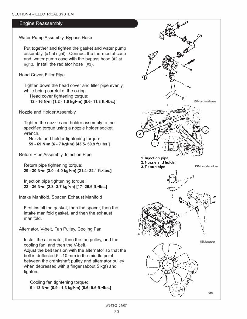
Water Pump Assembly, bypass Hose
Put together and tighten the gasket and water pump assembly. (#1 at right). Connect the thermostat case and water pump case with the bypass hose (#2 at right). Install the radiator hose (#3).
Head Cover, Filler Pipe
Tightendowntheheadcoverandfillerpipeevenly, while being careful of the o-ring. Head cover tightening torque: 12 - 16 N•m (1.2 - 1.6 kgf•m) [8.6- 11.8 ft.•lbs.]
Nozzle and Holder Assembly Tighten the nozzle and holder assembly to the specifiedtorqueusinganozzleholdersocket wrench. Nozzle and holder tightening torque: 59 - 69 N•m (6 - 7 kgf•m) [43.5- 50.9 ft.•lbs.]
Return Pipe Assembly, Injection Pipe
Return pipe tightening torque: 29 - 30 N•m (3.0 - 4.0 kgf•m) [21.4- 22.1 ft.•lbs.]
Injection pipe tightening torque: 23 - 36 N•m (2.3- 3.7 kgf•m) [17- 26.6 ft.•lbs.]
Intake manifold, Spacer, Exhaust manifold
First install the gasket, then the spacer, then the intake manifold gasket, and then the exhaust manifold.
Alternator, V-belt, Fan Pulley, Cooling Fan
Install the alternator, then the fan pulley, and the cooling fan, and then the V-belt. Adjust the belt tension with the alternator so that the beltisdeflected5-10mminthemiddlepoint between the crankshaft pulley and alternator pulley whendepressedwithafinger(about5kgf)and tighten.
Cooling fan tightening torque: 9 - 13 N•m (0.9 - 1.3 kgf•m) [6.6- 9.6 ft.•lbs.]
ISmnozzleholder
ISmspacer
fan
SECTION 4 – ELECTRICAL SySTEm

W843-2 04/07
31
SECTION 4 – ELECTRICAL SySTEm
Removal and Inspection
ISmfuelshutoff
ISmsealingwasher
Caution: Be sure to disconnect the negative (-) battery cable from the battery before starting any work on the electrical system. Electrical shock or damage to engine components could result could occur if this is not done. Some testing requires 12 volt power, extra care should be taken in these cases.
Fuel Shut-off Solenoid
The fuel shutoff solenoid is located on the right side of the engine, threaded into the rear of the fuel injection pump (#1 on picture at right). The shutoff solenoid contains a spring loaded plunger that pushes the control rack of the injection pump to the shut-off position (closed) when the solenoid is not energized. When the key switch is turned “On” or to “Start”, the safety stop relay closes to complete the circuit that energizes the solenoid. This then retracts the plunger from the injection pump and the control rack of the injection pump allows the engine to start.
Toremovethesolenoid,firstdisconnectthenegative (-) battery cable from the battery. Then disconnect the wiring harness lead from the fuel shutoff solenoid. Carefully remove the fuel shutoff solenoid from the engine with a pair of pliers. After removal, discard the sealing washer (#1 at right).
To test the solenoid; measure the protusion distance (“A”onfigureatright)on the solenoid. The distance should measure between 25.5 - 26.4 mm. If the distance is not within those perimeters, the solenoid is defective and needs to be replaced. Note: Be sure the paint is removed from the solenoid body when connecting the 12 volt power supply to the solenoid body, or power will not be transferred to the solenoid. Use jumper wires to connect the positive (+) terminal of a 12 volt power supply to the solenoid lead (#1 on rightfigure). Connect the negative terminal of the 12 volt power supply to the solenoid body (#2). The plunger should retract into the solenoid body (#3). measure the protrusion distance (“b” on right), it should be between 11.5 - 14.5 mm. If the distance is not within those perimeters or the plunger does not retract, the solenoid should be replaced. Reassembly in reverse of the above dis-assembly and install a new sealing washer on the solenoid.
ISmbattery
ISmsolenoidmeas

W843-2 04/07
32
Removal and Inspection
SECTION 4 – ELECTRICAL SySTEm
glow Plugs
The glow plugs are located on the right side of the engine cylinder head, next to the fuel injectors. (#1 on figureatright).The glow plugs preheat the air going to the pre-combustion chamber which helps in the starting of the engine when it’s cold.
Toremovetheglowplugsfortesting,firstdisconnect the negative (-) battery cable from the battery. Then remove the 3 nuts (#1 at right) and washers attaching the electrode bar (#2) to the glow plugs. Then remove the glow plugs from the engine cylinder head.
Totesttheglowplug,firstcleanthecarbonfromthe sheath end of the glow plug, but do not test resistance using the glow plug sheath. Using an ohmmeter, touch one test probe to the glow plug electrode. Touch the other test probe to the glow plug body. A normal reading is 1.0 ohms, maximum, for a standard glow plug. If the resistance measured is too high, the glow plug needs to be replaced.
To reinstall the glow plugs, thread the glow plugs into the engine cylinder head. Torque each glow plug to 15 - 20 N•m (1.5 ~ 2.0 kgf•m) [11- 14.7 ft.•lbs.]. Then install the electrode bar and put the washers on the glow plugs, and secure with the three nuts. Finally, connect the negative (-) battery cable back on the battery.
Oil Pressure Switch
The oil pressure switch (#1) is located on the front top of the cylinder head. The oil pressure switch closes (completes the circuit) when the oil pressure of the engine is less than 29.4 kPa. When this happens, an indicator light on the instrument panel should go on. The oil pressure switch is closed before the engine is started and opens after starting. If the switch does not work after starting, the oil level in the engine may be too low or there might be a problem with the oil pump. To test the oil pressure switch, use an ohmmeter and touch one lead to the pressure switch terminal (#1at right) and the other lead to the threads of the switch body (#2). There should be little or no resistance on the ohmmeter, indicating continuity in the switch. If there is no continuity the switch needs to be replaced.
ISmglowplugassemb
ISmbatterycable
ISmglowplugtest
ISmoilpressure1
ISmoilpressure2

W843-2 04/07
33
SECTION 4 – ELECTRICAL SySTEm
Removal and Inspection
Oil Pressure Switch (continued) While the test leads are connected to the switch, pressurize the switch at the port (#3 at right) with low pressure, 69~ 138 kPa (0.7~ 1.4 kgf/c m2) compressed air.
Note: Do not use high pressure compressed air as this may damage the oil pressure switch. This is not a calibrated test, the purpose is to see if the switch contacts open with pressure.
The ohmmeter should indicate high resistance while the air pressure is going to the pressure port (no continuity). If there appears to be continuity, the switch needs to be replaced. To reinstall the oil pressure switch - put it back into the cylinder head and tighten to 14.7~ 19.6 N•m (1.5~ 2.0 kgf•m) [10.8- 14.5 ft.•lbs]. Install the ring terminal onto the oil pressure switch, and secure the terminal with the retaining screw (#2).
ISmoilpressure2

W843-2 04/07
34
SECTION 4 – ELECTRICAL SySTEm
Removal and Inspection
A007TO3877 (mitsubishi)
Nominal output 12 volt 40 Amp
Polarity Negative ground
Weight 3.7 kg (8.2 lb.)
Rotational direction (viewed from Clockwisepulley) Load Terminal voltage 13.5 voltsChar. Current min. 30 amps(cold) Revolutions 2500 RPm
brush Original 18.5 mm (0.728”)Length Limit 5.0 mm (0.2”)brushspring Original 470~ 590g. (1.036~ 1.300 lb.)tension Limit 270 g. (0.60 lb.)
bearing Rear side ECSC8 Front side 6303DDgSlipRing o To be repaired 0.05 mm (.002”) wear Allowable limit 0.2 mm (0.08”)
Slip ring surface condition If dirty or damaged - correct with emery cloth.Rotorshaft To be repaired 0.07 mm (.0028”)bending
Field coil resistance 2.8 ohms at 5000 RPm
Adjusting voltage 14.4~ 15.0 volts at 5000 RPm
Alternator maintenance Chart

W843-2 04/07
35
Troubleshooting
Problem Parts Cause Solution
No charging Wiring, ammeter Possible disconnection, short circuit, Repair. loose connection. Alternator Disconnection of coils, ground short circuit. Defectiverectifier. Disconnection of RF resistor.
Replace. Regulator Defective regulator. Replace.
Weak charging Wiring Possible disconnection, short circuit, Repair. loose connection. Alternator Possible loose belt, rotor coil short, stator Repair or coilshort,defectiverectifier,insufficient Replace. contact of brush, stained slip ring. Regulator Defective regulator. Replace. battery Defective battery. Replace.
Over charging battery Internal short circuit. Replace. Regulator Defective regulator. Replace.
Unstablecharging Wiring Disconnection or wire broken. Replace.current Alternator Drive belt loose. Rotor coil short, wire broken, or stator coil short, wire broken. brush not contacting, or stained brush and slip ring. Possible broken brush and spring, or Repair or insufficientcontactofterminals. Replace. Regulator Defective regulator. Replace.
Abnormal Alternator installed incorrectly.noise of Alternator Defective bearing. Rotor core and statoralternator core in contact. Defective diode. Repair or Stator coil short. Replace.
SECTION 4 – ELECTRICAL SySTEm

W843-2 04/07
36
SECTION 4 – ELECTRICAL SySTEm
Removal and Inspection
Starter
This starter (Part #185086551) has a reduction mechanism with a planetary gearing system and permanentmagnetsformagneticfieldinduction. Its reduction internal gear is comprised of three planetary gears, gear shafts (with an over-running clutchfittedbyaspline)andanarmatureshaftgear. The structure is different from a direct drive type of starter, but the electrical wiring is the same between the two types. Themagneticfieldisproducedbysixpermanent magnets, which are mounted in the starter yoke and positioned according to polarity. These are permanently attached to the yoke and cannot be removed.
ISmstarterdwg
1. Rear bracket2. Armature3. Switch4. Internal gear5. Lever packing6. Lever7. Over-running clutch
15. magnets16. yoke17. brushes18. Sleeve bearing
8. Front bracket9. bearing10. Pinion11. gear shaft12. ball13. Planetary gears14. Rubber cover

W843-2 04/07
37
Starter (continued)
before disassembling the starter - be sure to put match marks both at the switch and yoke (or two locations) so that mistakes can be avoided at reassembly. be sure not to clamp the yoke in a vise or hit it with a hammer while repairing it as this could damage the permanent magnets or dent the yoke.
Todisassemblethestarter-firstremovetheterminal nut (#1onfigurebelow)and disconnect the connecting wire (#2). Then remove the screws (#3) that secure the switch and remove the switch and plunger (#4). Remove the brush holder screws (#5) and through bolts (#6). Remove the rear bracket (#7), but do not remove the brush holder (#8). Install a socket (of outer diameter 30 mm) on the armaturecommutator(seefigureatright).Thenslide the brush holder (#8) onto the socket. Leave the socket in position in the brush holder for inspection and reassembly. Slide the yoke (#9) away from the front bracket (#10). Remove the armature (#11) and ball (#12). Do not lose the ball when removing the armature.
ISmstartersock
ISmstarterassemb
SECTION 4 – ELECTRICAL SySTEm
Removal and Inspection

W843-2 04/07
38
Removal and Inspection
Starter (continued)
Remove the rubber cover (#13 starter assembly page 35 ) from planetary gear assembly (#23) and remove lever packing (#14) and plate (#15). Remove planetary gears (#16), then remove the gear shaft/ overrunning clutch assembly (#18) and lever (#19) as a unit from the front bracket (#10).
To remove the overrunning clutch (#18), firstremove the plastic cap (#20). If the cap is cracked or other wise damaged, it should be replaced for reassembly. Slide a piece of pipe of suitable size over the shaft against the stop ring (#21). Then tap the pipe with a hammer to remove the stop ring and expose the snap ring (#22). Remove the pipe from the shaft. Remove the snap ring and the stop ring and separate the over running clutch (#18) from the gear shaft (#17). If the snap ring is distorted it should be replaced for reassembly.
Inspect the armature with a growler tester; inspect the armature coil for short-circuit. If there is a short- circuit, replace the armature. Inspect the armature coil for ground with a circuit tester. Replace the armature if it is grounded. Inspect the commutator for wear. If it is below the limit, replace the armature. Also inspect the commutator for insulator depth, correct if below the limit. Check the gear teeth for wear or damage and replace the armature if needed.
Check the permanent magnets for cracks, damage, and whether or not they are loose. Replace the yoke assembly if necessary.
Check the brushes for wear. Replace the brushes if belowthelimitsspecified.Checkthebrushspring pressure to make sure the brush moves smoothly in the brush holder. To check the brush holder assembly for grounds, touch one probe of a circuit tester th the holder plate and the other probe to each of the insulated holders. Replace the brush holder assembly if any continuity is noted.
SECTION 4 – ELECTRICAL SySTEm
ISmsnapring
ISmarmature
ISmcommutator
ISmbrushes

W843-2 04/07
39
Starter (continued)
To inspect the over-running clutch and pinion gear, rotate the pinion while holding the clutch housing. The pinion should rotate smoothly in one direction (not necessarily easily) but should not rotate in the opposite direction. If the clutch is not functioning properly, replace it. If the pinion gear is worn or burred, replace that. Note: The over-running clutch should not be cleaned with grease dissolving solvents since these would dissolve the lubricant in the clutch mechanism.
Replace the front bracket as an assembly, including the ball bearing, if the bearing rotates ragged or noisily. If the bearing is worn badly on the rear bracket, replace the rear bracket as an assembly, including the sleeve bearing. Replace the gears on the planetary and internal gears if the teeth are badly worn. Check the switch by checking the continuity between the “m” terminal and body (ground). Replace the switch if no continuity is noted.
To reassembly the starter, reverse the disassembly stepsandfirstapplygreasetothefollowingshown parts. 1. Sleeve bearing and ball 2. Sleeve bearing in internal gear 3. Sleeve bearing in rear bracket 4. gear shaft 5. Sliding surface of lever and over-running clutch 6. Armature shaft gear, internal gear, and planetary gears 7. Sliding surfaces of pinion and front bearing
After completing the reassembly, check the pinion position to be sure that it is between 0.5 and 2.0 mm. To adjust the postion - connect the starter to a battery and close the switch. This will shift the pinion into a ranking position.
ISmstarterarmature
ISmterminalS
SECTION 4 – ELECTRICAL SySTEm
Removal and Inspection

W843-2 04/07
40
SECTION 4 – ELECTRICAL SySTEm
Removal and Inspection
Starter (continued)
Push the pinion back by hand and measure the amount of the pinion movement as shown on right figure.Ifthemeasurementdoesnotfallwithinthe limit (0.5~2.0 mm), adjust by adding or removing shims which are located between the switch and the front bracket. (Adding shims decreases the amount of the movement.) After adjusting the pinion postion, do a non-load test circuit with a voltmeter and an ammeter. Use wires as thick as possible and tighten each terminal fully. Close the switch and compare the RPm current and voltagereadingswiththeservicespecifications. Comparereadingswithinspectionfindings.
ISmstarter&battery
ISmpinion
Item Standard value or service limit
No-load Volts 11Char. Amps max. 110 amps RPm 2400 min.
Commutator Outer diameter 29.4 mm Service Limit 28.8 mm
brush Length 17.5 mm Service Limit 10 mm
brush Spring Tension 22.5~ 32.5 N Service Limit 10 N Pinion movement (Pinion gap) 0.5~ 2.0 mm
Starter maintenance Chart

W843-2 04/07
41
Notes
SECTION 4 – ELECTRICAL SySTEm

W843-2 04/07
42
Problem Parts Cause Solution
Pinion does not Wiring Possible disconnection, loose battery and Correct advance even when switch terminals, bad contacts. and retighten.the key switch is on Keyswitch Impropercontact-nocurrentflow. Correctorreplace
contact. Starter Helical spline of the pinion shaft is scored and prevents pinion from moving Repair or replace. magnet switch Improper movement of the plunger of the magnet switch or disconnected wire or short Repair or replace. circuit of the coil.motor rotation is not transmitted to the Starter Defective clutch. Replace.engine even though broken reduction gear. Replace.the pinion is is engaged and themotor rotates.
The starting motor Wiring The wire connecting the Repair or tightendoes not start even battery and magnet switch disconnected or replace thethough the pinion is or the lead wire connecting the magnet wire. engaged with the switch and the motor is loose. ring gear. Starter Locked ball bearing. Replace. Installed wrong. Install correctly. Worn out brush, brush spring not contacting. Replace. Stained commutator. Repair. Defectivearmatureorfieldcoil. Repairorreplace. Looseconnectionsofthefieldcoilandbrush. Retighten.
magnet switch broken holding coil. Replace. bad contacts. Replace. Contact surface rough. Replace. battery Not charged. Charge battery.
motor starts rotating Starter Improper sliding of pinion shaft Replace.before pinion is Worn out tooth top of pinion Repair.engaged with ring Pinion pushing position incorrect Replace.gear Engine Worn out ring gear. Replace. magnet switch Defective magnet switch. Replace.
SECTION 5 – TROUbLESHOOTINg
Troubleshooting, Starter

W843-2 04/07
43
Troubleshooting, Engine
Problem Cause Solution
Engine does not Defective key switch. Correct contact points.start battery not charged correctly. Charge battery. No fuel. Add fuel. Air in fuel system. Find where air is entering and
correct. Fuel injected improperly. Injection pump trouble. Have
repaired by authorized shop. glow plug defective. Replace. Oil viscosity wrong. Check and change oil. Clogged air cleaner. Clean. Cylinder compression off. Check and correct each part. Defective engine stop solenoid. Check wiring, replace if need be.
Irregular engine Air mixed in fuel system. bleed air from fuelspeed Uneven fuel injection. Injection pump faulty. Have repaired by authorized shop. Cloggedfuelfilter. Replacethefilter. governor faulty. Check and adjust.
Engine stops during No fuel. Fill up.operation Cloggedfuelfilter. Replacefilter. Airmixedinfuelsystem. Findwhereairisenteringandfix.
Engineoverheats Insufficientcoolant. Addcoolant,checkforleaks. Loose fan belt. Clean and retighten. Cloggedradiatororradiatorfins. Cleantheradiatorand/orfins. Coolant passage clogged. Clean. Thermostat not functioning. Test and replace if needed. Lubricating oil low. Fill. Load too high. Reduce load.
Engine Exhaust Too much engine oil. Check and adjust quantity.white color Low viscosity of engine oil. Check and change if necessary.
Ex haust black or Wrong fuel. Check and change.dark grey Load too high. Reduce load. Clogged air cleaner. Clean element.
Improper charging Fan belt loose. Correct belt tension. Wiring defective. Check and repair. battery or alternator defective. Replace.
Starting motor does Loose or disconnected wire. Check and repair.not operate battery voltage dropped. Charge battery. Safety switch defective. Replace. Fusible link wire disconnected. Replace.
SECTION 5 – TROUbLESHOOTINg

W843-2 04/07
44
SECTION 5 – TROUbLESHOOTINg
Troubleshooting, Engine
Problem Cause Solution
Oilpressurelamp Engineoillow. Filltospecifiedlevel.does not go out Oil pressure switch defective. Replace the switch. Lubricatingsystemleaksoil. Checkandfixleaks. Oilfilterclogged. Replacewithnewone. Wiring short circuited between oil pressure lamp and main contact. Repair wiring.
Oil pressure lampdoes not light up Lamp burned out. Replace lamp.with the key switch Disconnected wire between battery andturned on (while oil pressure lamp. Repair.engine is stopped)

W843-2 04/07
45
SECTION 6 – ENgINE mAINTENANCE STANDARDS
Engine main Parts
Inspection Items Standard Standard To be Allowable Remarks Dimension Value Repaired LimitCylinder Head
Compression pressure more than 2.94 Less than 2.45 Engine 250 RPmof cylinder mPa (kgf/cm2) (more than 30) (Less than 25)
Cylinder head tightening 98-103 (10.0-10.5) Coat threads withtorque N•m (kgf•m) [72.2-76 ft.•lbs.] engine oil.
Distortion of cyl. head Less than 0.05 0.12bottom surface
0.85 - 1.15 1.8 Valve sheet angle 450
Width of valve Intake 1.77 - 2.19 2.5seat Exhaust 1.87 - 2.09 2.5
Cylinder block
Cylinder bore diameter o84 o84 - 84.019 o84.2
Cyl. block upper face Less than 0.05 0.12distortion
Piston
Piston skirt bottom longer o o83.955 o83.948 - 83.963 o83.7Clearance between cyl. &piston 0.038 - 0.072 0.25 at 200C
Clearance between pistonpin hole and piston pin -0.001 - +0.011 0.02
Piston pin outside dia. o27.994 - 28.0 o27.97
Clearance between small Oilend bushing & piston pin 0.010 - 0.027 0.08 Clearance Top 0.20 - 0.35Piston ring end gap 2nd 0.20 - 0.40 1.0 Oil 0.25 - 0.50 1.2
Clearance between Top 0.07 - 0.11piston ring groove 2nd 0.04 - 0.08 0.25and ring Oil 0.02 - 0.06 Top 2Ring width 2nd 1.5 Oil 4
Note:Unitsnotspecifiedareinmm.

W843-2 04/07
46
SECTION 6 – ENgINE mAINTENANCE STANDARDS
Engine main Parts
Inspection Items Standard Standard To be Allowable Remarks Dimension Value Repaired LimitConnecting Rod
Torsion between small and Less than 0.08 more than 0.2 lg. end holes (per 100 mm)
Parallelism between sm. & Less than 0.05 more than 0.15 lg. end holes (per 100 mm)
Axial play of connecting 0.1 - 0.3 0.7rod and crank pin
Clearance between crank pin & connecting rod 0.035 - 0.085 0.2 Oil clearance
Connecting rod tightening 49 - 54 (5.0 - 5.5)torque N•m (kgf•m) [36- 39.8 ft.•lbs.]
Crankshaft
Diameter of journal o68 o67.957- 67970 o67.4
Diameter of crank pin o52 o51.964- 51.975 o51.4
main journal & crank pin 1.6Z
Crankshaft run out Less than 0.03 more than 0.06
Axial play of crankshaft 0.1 - 0.3 0.5
Thickness of thrust washer 3.0 2.95 - 3.00 2.8
O.D. x I.D. of bushing o68 x 72(journal metal)Clearance betweencrankshaft jnl. & bearing 0.044 - 0.116 0.2 Oil clearance
I.D. x O.D. of center bearing o68 x 72
Clearance between crank-shaft & center bearing 0.044 - 0.102 0.2
Camshaft For intake/ Exhaust 34.453- 34.508 34.1 For inj. Pump 42.94- 43.06 42.8
Camshaft run out Less than 0.03 more than 0.1Cam gearbacklash 0.08 0.25
Valve
Intake valve stem diameter 6.97 6.955- 6.97 6.89
Exhaust valve stem o 6.95 6.94- 6.95 6.84
Note:Unitsnotspecifiedareinmm.

W843-2 04/07
47
SECTION 6 – ENgINE mAINTENANCE STANDARDS
Engine main Parts
Inspection Items Standard Standard To be Allowable Remarks Dimension Value Repaired LimitValve more thanClearance between Inlet 0.03- 0.06 0.2valve stem and more thanvalve guide Exh. 0.045- 0.075 0.25
1.0 0.8- 1.1 0.5
Valve clearance intake/exh. 0.2 0.5
Valve Spring Spring Force N (kgf) 79.8 (8.1) 68.6 (7) Free length 35 33.5 Squareness Less than 1.2 2.0
Push rod length 177.8 177.6 - 178.0
Push rod outer diameter o6.3
Rocker arm shaft wear o14.96 o14.95- 14.97 o14.87
Clearance between rockerarm and shaft 0.032- 0.068 0.2 Oil clearance
Oil pumpDischarge rate: (L/min)Engine speed: 2500 RPmDischarge pressure: 16.2294-490 kPa (3-5 kgf/c m2)Oil temp.: 500C-800C (SAE30)
Oil pressure switchoperating pressure 29.4 (0.3) 19.6- 39.2 (0.2- 0.4)kPa(kgf/cm2)
Relief pressure kPa(kgf/cm2) 245- 343 (2.5-3.5)
OilCapacity(L) 6 Withfilterchange +0.5LTip clearance (rotor-to-vane) 0.1- 0.15 0.25
Side clearance (rotor-to-cover) 0.1- 0.15 0.2
Injection Pump
Injection timing before TDC 13 - 150
Piston displacement before TDC 843 1.510- 2.005
Inj. pressure mPa (kgf/cm2) 15.7 (160) 15.2- 16.2 (155-165)
Note:Unitsnotspecifiedareinmm.

W843-2 04/07
48
SECTION 6 – ENgINE mAINTENANCE STANDARDS
Engine main Parts
Inspection Items Standard Standard To be Allowable Remarks Dimension Value Repaired Limit
Angle of injection direction 40
Nozzle and holder tightening with cylinder headtorque N•m (kgf•m) 59 - 69 (6 - 7) installed
Cooling System Coolant water volume (L) 5.0 Reserve tank 0.6L
Thermostat open temperature 820C
Thermostat full-open temp. 950C
V belt (fan) loose (load at center 5 kg) 5 - 10
Starter
No. of teeth of pinion gear: 11magnetic shifting of pinion
Wear of commutator diameter o29.4 o28.8
Stepped wear of commutator 0.05 0.2
bending allowance of more thanarmature shaft 0.05 0.08
Length of brush 17.5 9
Spring force of brush N (kgf) 22.5- 32.5 (2.3 - 3.3) Less than 8.8 (0.9)
Alternator, 12 volt 40 amp
Outside diameter of slip ring 22.7 22.1
Length of brush 18.5 5.0
Pulley tightening torqueN•m (kgf•m) 58 - 79 (5.95- 8.05)
Note:Unitsnotspecifiedareinmm.


